EP3376152A1 - Système de traitement d'informations et procédé de traitement d'informations - Google Patents
Système de traitement d'informations et procédé de traitement d'informations Download PDFInfo
- Publication number
- EP3376152A1 EP3376152A1 EP17204122.0A EP17204122A EP3376152A1 EP 3376152 A1 EP3376152 A1 EP 3376152A1 EP 17204122 A EP17204122 A EP 17204122A EP 3376152 A1 EP3376152 A1 EP 3376152A1
- Authority
- EP
- European Patent Office
- Prior art keywords
- information processing
- processing system
- detection results
- relevant
- output
- Prior art date
- Legal status (The legal status is an assumption and is not a legal conclusion. Google has not performed a legal analysis and makes no representation as to the accuracy of the status listed.)
- Withdrawn
Links
Images



Classifications
-
- F—MECHANICAL ENGINEERING; LIGHTING; HEATING; WEAPONS; BLASTING
- F41—WEAPONS
- F41G—WEAPON SIGHTS; AIMING
- F41G3/00—Aiming or laying means
- F41G3/02—Aiming or laying means using an independent line of sight
-
- F—MECHANICAL ENGINEERING; LIGHTING; HEATING; WEAPONS; BLASTING
- F41—WEAPONS
- F41G—WEAPON SIGHTS; AIMING
- F41G3/00—Aiming or laying means
- F41G3/04—Aiming or laying means for dispersing fire from a battery ; for controlling spread of shots; for coordinating fire from spaced weapons
-
- F—MECHANICAL ENGINEERING; LIGHTING; HEATING; WEAPONS; BLASTING
- F41—WEAPONS
- F41G—WEAPON SIGHTS; AIMING
- F41G3/00—Aiming or laying means
- F41G3/14—Indirect aiming means
- F41G3/16—Sighting devices adapted for indirect laying of fire
- F41G3/165—Sighting devices adapted for indirect laying of fire using a TV-monitor
-
- F—MECHANICAL ENGINEERING; LIGHTING; HEATING; WEAPONS; BLASTING
- F41—WEAPONS
- F41G—WEAPON SIGHTS; AIMING
- F41G9/00—Systems for controlling missiles or projectiles, not provided for elsewhere
-
- G—PHYSICS
- G01—MEASURING; TESTING
- G01S—RADIO DIRECTION-FINDING; RADIO NAVIGATION; DETERMINING DISTANCE OR VELOCITY BY USE OF RADIO WAVES; LOCATING OR PRESENCE-DETECTING BY USE OF THE REFLECTION OR RERADIATION OF RADIO WAVES; ANALOGOUS ARRANGEMENTS USING OTHER WAVES
- G01S7/00—Details of systems according to groups G01S13/00, G01S15/00, G01S17/00
- G01S7/003—Transmission of data between radar, sonar or lidar systems and remote stations
-
- G—PHYSICS
- G06—COMPUTING OR CALCULATING; COUNTING
- G06V—IMAGE OR VIDEO RECOGNITION OR UNDERSTANDING
- G06V20/00—Scenes; Scene-specific elements
- G06V20/10—Terrestrial scenes
- G06V20/13—Satellite images
-
- G—PHYSICS
- G06—COMPUTING OR CALCULATING; COUNTING
- G06V—IMAGE OR VIDEO RECOGNITION OR UNDERSTANDING
- G06V20/00—Scenes; Scene-specific elements
- G06V20/20—Scenes; Scene-specific elements in augmented reality scenes
-
- G—PHYSICS
- G06—COMPUTING OR CALCULATING; COUNTING
- G06V—IMAGE OR VIDEO RECOGNITION OR UNDERSTANDING
- G06V20/00—Scenes; Scene-specific elements
- G06V20/50—Context or environment of the image
- G06V20/52—Surveillance or monitoring of activities, e.g. for recognising suspicious objects
-
- B—PERFORMING OPERATIONS; TRANSPORTING
- B64—AIRCRAFT; AVIATION; COSMONAUTICS
- B64U—UNMANNED AERIAL VEHICLES [UAV]; EQUIPMENT THEREFOR
- B64U2101/00—UAVs specially adapted for particular uses or applications
- B64U2101/20—UAVs specially adapted for particular uses or applications for use as communications relays, e.g. high-altitude platforms
-
- B—PERFORMING OPERATIONS; TRANSPORTING
- B64—AIRCRAFT; AVIATION; COSMONAUTICS
- B64U—UNMANNED AERIAL VEHICLES [UAV]; EQUIPMENT THEREFOR
- B64U2101/00—UAVs specially adapted for particular uses or applications
- B64U2101/30—UAVs specially adapted for particular uses or applications for imaging, photography or videography
-
- G—PHYSICS
- G01—MEASURING; TESTING
- G01S—RADIO DIRECTION-FINDING; RADIO NAVIGATION; DETERMINING DISTANCE OR VELOCITY BY USE OF RADIO WAVES; LOCATING OR PRESENCE-DETECTING BY USE OF THE REFLECTION OR RERADIATION OF RADIO WAVES; ANALOGOUS ARRANGEMENTS USING OTHER WAVES
- G01S13/00—Systems using the reflection or reradiation of radio waves, e.g. radar systems; Analogous systems using reflection or reradiation of waves whose nature or wavelength is irrelevant or unspecified
- G01S13/02—Systems using reflection of radio waves, e.g. primary radar systems; Analogous systems
- G01S13/50—Systems of measurement based on relative movement of target
- G01S13/58—Velocity or trajectory determination systems; Sense-of-movement determination systems
-
- G—PHYSICS
- G01—MEASURING; TESTING
- G01S—RADIO DIRECTION-FINDING; RADIO NAVIGATION; DETERMINING DISTANCE OR VELOCITY BY USE OF RADIO WAVES; LOCATING OR PRESENCE-DETECTING BY USE OF THE REFLECTION OR RERADIATION OF RADIO WAVES; ANALOGOUS ARRANGEMENTS USING OTHER WAVES
- G01S13/00—Systems using the reflection or reradiation of radio waves, e.g. radar systems; Analogous systems using reflection or reradiation of waves whose nature or wavelength is irrelevant or unspecified
- G01S13/02—Systems using reflection of radio waves, e.g. primary radar systems; Analogous systems
- G01S13/50—Systems of measurement based on relative movement of target
- G01S13/58—Velocity or trajectory determination systems; Sense-of-movement determination systems
- G01S13/62—Sense-of-movement determination
-
- G—PHYSICS
- G01—MEASURING; TESTING
- G01S—RADIO DIRECTION-FINDING; RADIO NAVIGATION; DETERMINING DISTANCE OR VELOCITY BY USE OF RADIO WAVES; LOCATING OR PRESENCE-DETECTING BY USE OF THE REFLECTION OR RERADIATION OF RADIO WAVES; ANALOGOUS ARRANGEMENTS USING OTHER WAVES
- G01S13/00—Systems using the reflection or reradiation of radio waves, e.g. radar systems; Analogous systems using reflection or reradiation of waves whose nature or wavelength is irrelevant or unspecified
- G01S13/66—Radar-tracking systems; Analogous systems
- G01S13/72—Radar-tracking systems; Analogous systems for two-dimensional [2D] tracking, e.g. combination of angle and range tracking, track-while-scan radar
- G01S13/723—Radar-tracking systems; Analogous systems for two-dimensional [2D] tracking, e.g. combination of angle and range tracking, track-while-scan radar by using numerical data
-
- G—PHYSICS
- G01—MEASURING; TESTING
- G01S—RADIO DIRECTION-FINDING; RADIO NAVIGATION; DETERMINING DISTANCE OR VELOCITY BY USE OF RADIO WAVES; LOCATING OR PRESENCE-DETECTING BY USE OF THE REFLECTION OR RERADIATION OF RADIO WAVES; ANALOGOUS ARRANGEMENTS USING OTHER WAVES
- G01S17/00—Systems using the reflection or reradiation of electromagnetic waves other than radio waves, e.g. lidar systems
- G01S17/02—Systems using the reflection of electromagnetic waves other than radio waves
- G01S17/50—Systems of measurement based on relative movement of target
- G01S17/58—Velocity or trajectory determination systems; Sense-of-movement determination systems
-
- G—PHYSICS
- G01—MEASURING; TESTING
- G01S—RADIO DIRECTION-FINDING; RADIO NAVIGATION; DETERMINING DISTANCE OR VELOCITY BY USE OF RADIO WAVES; LOCATING OR PRESENCE-DETECTING BY USE OF THE REFLECTION OR RERADIATION OF RADIO WAVES; ANALOGOUS ARRANGEMENTS USING OTHER WAVES
- G01S17/00—Systems using the reflection or reradiation of electromagnetic waves other than radio waves, e.g. lidar systems
- G01S17/88—Lidar systems specially adapted for specific applications
- G01S17/89—Lidar systems specially adapted for specific applications for mapping or imaging
-
- G—PHYSICS
- G01—MEASURING; TESTING
- G01S—RADIO DIRECTION-FINDING; RADIO NAVIGATION; DETERMINING DISTANCE OR VELOCITY BY USE OF RADIO WAVES; LOCATING OR PRESENCE-DETECTING BY USE OF THE REFLECTION OR RERADIATION OF RADIO WAVES; ANALOGOUS ARRANGEMENTS USING OTHER WAVES
- G01S7/00—Details of systems according to groups G01S13/00, G01S15/00, G01S17/00
- G01S7/02—Details of systems according to groups G01S13/00, G01S15/00, G01S17/00 of systems according to group G01S13/00
- G01S7/41—Details of systems according to groups G01S13/00, G01S15/00, G01S17/00 of systems according to group G01S13/00 using analysis of echo signal for target characterisation; Target signature; Target cross-section
- G01S7/415—Identification of targets based on measurements of movement associated with the target
Definitions
- the present invention relates to an information processing system and a corresponding information processing method.
- Emergency and rescue workers e.g. police, military, fire or the like, often have to cope in confusing situations. For example, police forces often have to track one or more people in confusing urban neighborhoods. Rescuers must be able to withstand major events, such as a fire in a factory or a mass panic at a major event, can quickly locate and rescue people in need of assistance. In the military field, soldiers must, for example, often in unknown urban or rural terrain and carry out combat operations.
- a person e.g. a police or a soldier, has a limited field of view and a limited range of motion. In all of the above scenarios, it is therefore difficult for each individual to gain an overview of the overall situation on their own.
- a system that supports emergency personnel in communication is, for example, in the US 5,864,481 shown.
- the object of the present invention is to provide improved information processing for emergency services.
- an information processing system for a plurality of users for enriching surrounding information about a relevant area.
- the information processing system comprises at least one detection device, which can be carried by the users and which is designed to detect relevant objects and output corresponding detection results, and at least one output device, which is each carried by a user and which is designed for the respective user, the detection results issue.
- an information processing method is provided to a plurality of users for enriching surrounding information about a relevant area.
- the information processing method comprises the following steps: detecting relevant objects by at least one of the users with at least one detection device, providing corresponding detection results, and outputting the detection results for another user by at least one output device.
- the present invention employs a plurality of detectors to detect events in the relevant area.
- the detection means may e.g. be carried by the users of the information processing system and detect objects in the relevant area.
- a user of the information processing system is to be understood as meaning all units that can be integrated in the information processing system. Such units may include human forces, but also controlled or autonomous vehicles and flying objects or the like.
- the detection devices may, for example, have corresponding sensors that enable them to detect the relevant objects.
- Which objects in the relevant area are to be classified as relevant objects can be predefined, for example, before the beginning of a deployment of the information processing system.
- people, vehicles and aircraft can be classified as relevant objects.
- specific persons eg persons who shout aloud or lie on the floor, can be targeted as relevant objects. For example, after an earthquake or a storm in hard-to-reach areas, damaged homes and injured people can be given as relevant objects.
- the information processing system can also be used eg in forestry.
- drones can be used to identify sick trees in a large forest stock and their positions capture. These can then be transmitted as detection results to a forester.
- the detection means may comprise, for the detection of the relevant objects, any type of sensor capable of detecting the respective object and its position.
- sensors may e.g. GPS sensors, camera-based sensors, laser or radar sensors, ultrasonic sensors, infrared sensors or the like.
- the detectors may also employ stereoscopic image capture and triangulation techniques. This allows a higher granularity of the collected data.
- the detection of the relevant objects can take place with the aid of corresponding detection algorithms, which are applied to the respective sensor signals. It is understood that individual users, e.g. (Partial) autonomous drones or drone swarms may also have multiple types of sensors to detect the relevant objects.
- the information processing system now makes it possible to transmit the detection results of other users to the individual users and to output them by means of corresponding output devices, ie to enrich their information base.
- the environment information that a user already possesses can therefore be enriched with further information.
- information about the position of a relevant object can be transmitted to a user.
- soldiers can obtain information about relevant objects that are out of their field of vision and plan their actions better with the help of this information.
- in the information processing system according to the invention in the detection results only already extracted information about the relevant objects instead of images. As a result, the required bandwidth can be kept low.
- situation-favorable users Those users who can detect a relevant object on the basis of their position are also referred to as situation-favorable users in the context of this invention. Those users who can not detect a relevant object because of their position are also referred to as situation-disadvantaged users in the context of this invention. In this case, it may happen that a user who is situation-favorable with respect to a relevant object with respect to another object is at the same time a situation-disadvantaged user.
- a situation-favorable user may e.g. also a network of public surveillance cameras, e.g. at a railway station or in a city area.
- the information base of the individual users can be harmonized and a comprehensive basis for decision-making can be provided.
- the information processing system can have a communication network which couples the detection devices and the output devices to each other in a data-communicative connection.
- the detection devices and the output devices can consequently have corresponding communication hardware which allows them to participate the communication network allows.
- the communication network can be managed, for example, by a central server which receives and forwards the data of the individual subscribers.
- the communication network can also be, for example, a so-called meshed network in which no central server manages the communication, but each node is connected to one or more other nodes.
- Such a meshed network can be a self-healing network in which failed nodes are detected and replaced or bridged.
- such a meshed network may be an ad hoc network that new subscribers can join as soon as they reach within range of the network.
- the communication network may include both wireless and wired links.
- the detectors and the output devices may communicate wirelessly with each other and / or with a backbone network.
- a backbone network may itself have a plurality of wired connections.
- the communication network can encrypt the data communication.
- corresponding hardware and / or software can be provided in each of the network participants, which enables encryption of the transmitted data with sufficiently secure encryption.
- the information processing system can have a display device for at least one of the users, which is designed to display the detection results output by the respective output device for the user.
- the display device may e.g. be carried by human users and show them the positions of the relevant objects.
- the display device may be a screen displaying a map section indicating the position of the user and the relevant objects.
- the display device can also be an augmented reality display which superimposes the detection results on a field of view of the user. So, for example, if a user is looking on a wall, but behind which a relevant object has been identified, the object can still be displayed by the augmented reality display.
- Such an object may e.g. shown as an outline in a selectable color.
- the detection devices can be designed to detect the position and / or the type and / or the posture and / or an orientation and / or the speed and / or an orientation of the relevant objects.
- the detection means may acquire a plurality of information about the relevant objects and output it in the detection result.
- the detection means adjacent to the position, e.g. an absolute geographical position, including the type, attitude and orientation of the object.
- a detection device may thus e.g. determine if it lies, kneels or stands and in which direction it looks.
- detection means may e.g. detect the orientation of the vehicle or components of the vehicle.
- a detection device can detect the direction of travel of the tank and the orientation of the turret separately.
- the detection devices can also detect an attitude of the relevant objects.
- the detectors may detect whether it is a separate or allied unit or an enemy unit.
- the detection means may be e.g. Have sensors and suitable detection algorithms. Such recognition algorithms may e.g. Have image and object recognition algorithms or algorithms based on machine learning.
- the detection means may be e.g. also transmit images of the objects to a central evaluation point, which automatically and / or manually supports the evaluation.
- the recognition of the attitude can e.g. based on an evaluation of flags or symbols, which are attached to a relevant object. Additionally or alternatively, radio signals or identifiers of the relevant objects can be evaluated.
- the display device can be designed to display the data contained in the detection results for the user.
- the display device may e.g. Use pictograms to display the position, type, posture, orientation, speed and attitude of the relevant objects.
- the display device may also display images of the relevant objects, e.g. complete with pictograms.
- the display device may e.g. display a picture of a person kneeling and indicate with a pictogram above the picture whether it is a friendly or a hostile person.
- the display device can have an object memory in which images of different types of objects are stored. Receives the display device the information that a certain object has been detected, no image of the object must be transmitted but the display device can load the corresponding image from the object memory.
- the output devices can be designed to calculate a movement of the relevant objects based on the detection results and to output a possible trajectory of the relevant objects.
- the detection devices can also calculate the possible trajectory or that a central processing unit can be provided for this task.
- the data acquired and transmitted in the detection results may, as explained above, e.g. have an orientation and a speed of one of the relevant objects. Based on this data, a projection of the position of the relevant object for the future can be performed. It can also be considered terrain properties. If a vehicle is moving e.g. On a road, it can be assumed that the vehicle does not follow or follow the road. The vehicle will therefore also drive on the road a curve, if the road dictates this and not go straight.
- the estimated or possible trajectories may be separately marked on the display for the user.
- the detection devices can be designed to detect static features of the relevant area.
- the output devices can be designed to create and output a virtual model of the relevant area, which comprises a combination of the static features and the detected relevant objects.
- the information on the static features may alternatively not be captured in real time.
- the information about the static features may e.g. already known from pre-deployment intelligence or publicly available data sources.
- static features all non-variable objects in the relevant area can be considered. Examples of such objects are e.g. Houses, mountains, roads, trees and the like.
- the information about the static features can be used to create a static model of the relevant area.
- This static model may e.g. be made available as a 3D model, allowing a user to plan and simulate his actions before performing them.
- the scenery can be viewed from any perspective and the data can be displayed in a different form.
- the view of an enemy or a fine radar can be simulated or a trajectory can be represented.
- the information about static features may be combined with the information about the relevant objects.
- a user can e.g. relevant objects that are out of his field of vision, e.g. behind a wall or in a building.
- the data on the static features may also be used by the output devices or the display devices to detect the position of the user and to synchronize with the model of the relevant area. For example, buildings covered by an augmented reality system, roads, Trees or the like or their positions and distances to the user are compared with the model of the relevant area and so the position of the respective user are determined or verified.
- Fig. 1 Fig. 12 shows a schematic representation of an information processing system 100.
- the information processing system 100 has a first user, who is a drone 101, who independently monitors a given area.
- the drone 101 has for this purpose a detection device 102 and outputs corresponding detection results 103.
- the information processing system 100 further illustrates a second user who is a soldier 104.
- the soldier 104 carries an output device 105 which receives the detection results 103 and displays them via a display device 106 for the soldier 104.
- the drone 101 and the output device 105 are wirelessly coupled to each other and have respective antennas 107, 108 and communication modules for data transmission.
- a wall 120 is shown schematically, behind which a person 121 kneels. Since the person 121 is covered by the wall 120, the soldier 104 has no visual contact with the person 121 or no knowledge of its existence.
- the information handling system 100 may assist the soldier 104 in such a situation by wirelessly transmitting the detection results 103 of the drone 101 to the dispenser 105 and displaying it to the soldier 104. Although the soldier 104 has no line of sight to the person 121, he can be informed by means of the information processing system 100 that the person 121 is behind the wall 120. With the help of this information, the soldier 104 can plan his further course of action.
- the detection device 102 may comprise a camera, a radar, an infrared sensor or the like. With the aid of these sensors, the detection device 102 can not only detect a position of the person 121. Rather, it is possible, for example, to provide further image and object recognition algorithms, with the aid of which the detection device 102 also determines the type, the posture, the orientation, the speed and / or an attitude (cf. Fig. 2 ) of the person 121 can recognize. Furthermore, the detection device 102 can, for example, also detect and output arming of the person 121.
- the display device 106 is in Fig. 1 only shown schematically. It will be appreciated, however, that the display 106 may be any suitable type of display 106.
- the display 106 may include a screen that the soldier 104 may view.
- the display device 106 may also be, for example, a head-up or augmented reality display which displays information directly in the field of vision of the soldier 104.
- the display 106 may also display the information for the soldier 104 in a different manner.
- the display device 106 may display the detection results 103 e.g. as text. Additionally or alternatively, the display device 106 may also display the detection results 103 graphically and, e.g. visualize a picture or model of person 121. For this purpose, the display 106 may be e.g. overlay a map or image of the relevant site with the appropriate information. Furthermore, the display device 106 can take into account the orientation or orientation of the soldier 104 and rotate the map or the respective terrain cutout accordingly.
- both the drone 101 e.g. Also, the output device 105 or the display device 106 each detect their environment and static features, such. capture the wall 120. If the static features are also detected, a 3D model of the environment can be generated and the detected objects, e.g. the person 121, can be represented in the model. This allows the soldier 104 a more accurate location of the person 121 and thus better planning his approach.
- the drone 101 and the output device 105 directly communicate with each other. It is understood, however, that in the information processing system 100 may be a plurality of users integrated. The individual users or their output devices 105 can communicate with one another in such a case in a meshed ad hoc network. Such networks offer a high degree of fault tolerance and can heal themselves, ie replace failed nodes. It is understood, however, that any other type of network may also be used.
- the reconnaissance work may also perform a person or a vehicle instead of the drone 101.
- the soldier 104 can also provide information and can provide the knowledge gained by him for other users of the information processing system 100.
- the drone 101 and the soldier 104 and other users, not shown, can thus be both situation-favorable users and situation-disadvantaged users.
- the respective classification depends only on the area considered and the objects detectable by the respective user in the area.
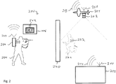
- Fig. 2 11 shows a schematic representation of an information processing system 200.
- the information processing system 200 is based on the information processing system 100 and supplements this with a central server 209, which forms a communication network via the antennas 210, 207 and 208 with the drone 201 and the output device 205.
- the server 209 provides support functions to the other users 201, 204 of the information handling system 200.
- server 209 may apply complex image and object recognition algorithms to imagery captured by drone 201 or soldier 204.
- the Complexity and the need for computing power and energy can thus be kept low for the individual users or their equipment.
- the server 209 may be e.g. Perform the friend / enemy detection based on the images taken by the drone 201.
- the person 221 in Fig. 2 carries on its jacket a flag 222.
- This flag 222 can be recognized in the captured by the drone 201 images by the server 209.
- the soldier 204 wears the same flag on his uniform.
- the person 221 can therefore be marked as a friend. This is shown in the display of the display device 206 by the icon 212.
- a broadband data connection between the server 209 and the drone 201 are used whose data rate is above the data rate for communication with the output device 205.
- the raw data which the detection device 202 receives is transmitted via satellite connection to the server 209 and evaluated by the latter.
- the communication between the server 209 and the soldier 204 or a plurality of soldiers may be e.g. via a mesh network already mentioned above.
- the flag 222 is just one example of a possible identification feature. Of course, other features can be used to perform a friend / enemy detection.
- the users of the information handling system 200 may carry radio transmitters that issue an identification.
- FIG. 12 shows a schematic diagram of another information processing system 300.
- the information processing system 300 is based on the information processing system 100 and serves to explain other functions that the information processing system 300 can perform.
- the drone 301 detects by means of a camera 302 or other sensors a vehicle 323 which moves behind a wall 320 at a constant speed.
- the vehicle 323 may be e.g. to trade a tank that is in patrol.
- the drone 301 In addition to the position of the vehicle 323, the drone 301 also detects its speed. This information is transmitted to the output device 305 of the soldier 304 where it is evaluated and processed.
- the display device 306 may now also display an estimated trajectory 313 for the vehicle 323 in addition to the position of the vehicle 323.
- the soldier 304 without direct visual contact with the vehicle 323, can see where and where this is moving.
- the calculation of trajectories 313 may be e.g. be outsourced to a server 209, if it is present.
- the available functions may be e.g. be dynamically adjusted or enabled or disabled depending on the existing in the information processing system 300 computing power and data transmission bandwidth.
- Fig. 4 shows a schematic representation of another information processing system 400.
- the information processing system 400 is only the Drone 401, which flies over a relevant area 424 and outputs corresponding detection results 403.
- the detection device 402 can have any type of suitable sensor. Such sensors may be cameras, laser sensors, radar sensors or the like.
- a 3D model of area 424 can be created and a mission planned in advance. In doing so, movements of one's own troops can be simulated and different possible reactions of enemy troops analyzed and appropriate countermeasures planned. Further, e.g. during deployment of a guided missile, the area is monitored and the path of the missile is adjusted accordingly.
- Fig. 4 are shown next to the drone 401 no other users. This is to clarify that the detection of the detection results 403 does not have to take place exclusively in real time. Rather, the detection results 403 can already be detected in advance and used later during a mission. Furthermore, data obtained in advance, for example via the static features of the terrain 424, can also be combined during a mission with data obtained live or in real time.
- a drone was presented as the user who recorded the information about objects in the relevant area. It is understood that any other user can also capture such information.
- each of the soldiers can carry a helmet camera with them, which permanently films the field of vision of the soldier.
- a downstream image and object recognition for example in the output device or the display device, can then recognize the relevant objects and share the information obtained with other users.
- the output device and the display device have been shown as devices that provide graphical information to a user. It is understood that the output device but e.g. also digital information for further processing by a controller e.g. can spend a drone.
- FIG. 10 is a flow chart of an information processing method for a plurality of users 101, 104, 201, 204, 301, 304, 401 for enriching surrounding information about a relevant area 424.
- the information processing method comprises detecting relevant objects 121, 221, 323 by at least one of the users 101, 104, 201, 204, 301, 304, 401 with at least one detection device 102, 202, 302, 402.
- the relevant objects 121, 221, 323 may be, for example, humans, vehicles and aircraft, which are detected by means of cameras, laser or infrared sensors or the like.
- the relevant objects 121, 221, 323, or their properties can be determined. whose position, nature, attitude, orientation, speed and / or attitude are detected.
- static features of the relevant area 424 can also be detected. Such static features may e.g. Buildings, walls, trees, roads and the like.
- the detection results 103, 203, 303, 403 are provided to a plurality of users 101, 104, 201, 204, 301, 304, 401 in step S2.
- the detection results 103, 203, 303, 403 for at least one other user 101, 104, 201, 204, 301, 304, 401 are output by at least one output device 105, 205, and e.g. displayed graphically.
- a movement of the relevant objects 121, 221, 323 can be calculated and a possible trajectory 313 of the relevant objects 121, 221, 323 output.
- the at least one detection device 102, 202, 302, 402 can be coupled to the at least one output device 105, 205 in a data-communicative connection, for example in a meshed ad-hoc network. This enables a very robust data transmission.
Landscapes
- Engineering & Computer Science (AREA)
- Physics & Mathematics (AREA)
- General Physics & Mathematics (AREA)
- Multimedia (AREA)
- Theoretical Computer Science (AREA)
- General Engineering & Computer Science (AREA)
- Remote Sensing (AREA)
- Astronomy & Astrophysics (AREA)
- Computer Networks & Wireless Communication (AREA)
- Radar, Positioning & Navigation (AREA)
- Traffic Control Systems (AREA)
Applications Claiming Priority (1)
| Application Number | Priority Date | Filing Date | Title |
|---|---|---|---|
| DE102017204107.2A DE102017204107A1 (de) | 2017-03-13 | 2017-03-13 | Informationsverarbeitungssystem und Informationsverarbeitungsverfahren |
Publications (1)
| Publication Number | Publication Date |
|---|---|
| EP3376152A1 true EP3376152A1 (fr) | 2018-09-19 |
Family
ID=60673092
Family Applications (1)
| Application Number | Title | Priority Date | Filing Date |
|---|---|---|---|
| EP17204122.0A Withdrawn EP3376152A1 (fr) | 2017-03-13 | 2017-11-28 | Système de traitement d'informations et procédé de traitement d'informations |
Country Status (2)
| Country | Link |
|---|---|
| EP (1) | EP3376152A1 (fr) |
| DE (1) | DE102017204107A1 (fr) |
Cited By (2)
| Publication number | Priority date | Publication date | Assignee | Title |
|---|---|---|---|---|
| WO2020077387A1 (fr) | 2018-10-15 | 2020-04-23 | Towarra Holdings Pty. Ltd. | Dispositif d'affichage cible |
| EP4341633A2 (fr) | 2021-05-18 | 2024-03-27 | Code Planet Saver Oy | Système d'acquisition de cible pour un engin volant sans pilote |
Citations (5)
| Publication number | Priority date | Publication date | Assignee | Title |
|---|---|---|---|---|
| US5200827A (en) * | 1986-07-10 | 1993-04-06 | Varo, Inc. | Head mounted video display and remote camera system |
| US5864481A (en) | 1996-01-22 | 1999-01-26 | Raytheon Company | Integrated, reconfigurable man-portable modular system |
| US20150054826A1 (en) * | 2009-03-19 | 2015-02-26 | Real Time Companies | Augmented reality system for identifying force capability and occluded terrain |
| WO2015066531A1 (fr) * | 2013-10-31 | 2015-05-07 | Aerovironment, Inc. | Système interactif de ciblage d'une arme, affichant une image détectée à distance de la zone cible |
| EP2950035A1 (fr) * | 2014-05-28 | 2015-12-02 | Patents Factory Ltd. Sp. z o.o. | Procédé et système pour visualisation tactique |
Family Cites Families (3)
| Publication number | Priority date | Publication date | Assignee | Title |
|---|---|---|---|---|
| GB9918248D0 (en) | 1999-08-04 | 1999-10-06 | Matra Bae Dynamics Uk Ltd | Improvements in and relating to surveillance systems |
| US20060176169A1 (en) | 2004-12-17 | 2006-08-10 | The Regents Of The University Of California | System for sensing environmental conditions |
| US9063544B2 (en) | 2012-09-19 | 2015-06-23 | The Boeing Company | Aerial forest inventory system |
-
2017
- 2017-03-13 DE DE102017204107.2A patent/DE102017204107A1/de active Pending
- 2017-11-28 EP EP17204122.0A patent/EP3376152A1/fr not_active Withdrawn
Patent Citations (5)
| Publication number | Priority date | Publication date | Assignee | Title |
|---|---|---|---|---|
| US5200827A (en) * | 1986-07-10 | 1993-04-06 | Varo, Inc. | Head mounted video display and remote camera system |
| US5864481A (en) | 1996-01-22 | 1999-01-26 | Raytheon Company | Integrated, reconfigurable man-portable modular system |
| US20150054826A1 (en) * | 2009-03-19 | 2015-02-26 | Real Time Companies | Augmented reality system for identifying force capability and occluded terrain |
| WO2015066531A1 (fr) * | 2013-10-31 | 2015-05-07 | Aerovironment, Inc. | Système interactif de ciblage d'une arme, affichant une image détectée à distance de la zone cible |
| EP2950035A1 (fr) * | 2014-05-28 | 2015-12-02 | Patents Factory Ltd. Sp. z o.o. | Procédé et système pour visualisation tactique |
Cited By (8)
| Publication number | Priority date | Publication date | Assignee | Title |
|---|---|---|---|---|
| WO2020077387A1 (fr) | 2018-10-15 | 2020-04-23 | Towarra Holdings Pty. Ltd. | Dispositif d'affichage cible |
| KR20210100090A (ko) * | 2018-10-15 | 2021-08-13 | 토와라 홀딩스 피티와이. 엘티디. | 목표 디스플레이 장치 |
| AU2019362275B2 (en) * | 2018-10-15 | 2022-01-13 | Towarra Holdings Pty. Ltd. | Target display device |
| JP2022508769A (ja) * | 2018-10-15 | 2022-01-19 | トゥワラ ホールディングス ピーティーワイ. エルティーディー. | 標的表示装置 |
| US11378358B2 (en) * | 2018-10-15 | 2022-07-05 | Towarra Holdings Pty. Ltd. | Target display device |
| EP4341633A2 (fr) | 2021-05-18 | 2024-03-27 | Code Planet Saver Oy | Système d'acquisition de cible pour un engin volant sans pilote |
| US20240263920A1 (en) * | 2021-05-18 | 2024-08-08 | Code Planet Saver Oy | Target acquisition system for an unmanned air vehicle |
| EP4341633A4 (fr) * | 2021-05-18 | 2025-03-19 | Code Planet Saver Oy | Système d'acquisition de cible pour un engin volant sans pilote |
Also Published As
| Publication number | Publication date |
|---|---|
| DE102017204107A1 (de) | 2018-09-13 |
Similar Documents
| Publication | Publication Date | Title |
|---|---|---|
| DE60213526T2 (de) | Verfahren und System zur Verbesserung des Situationsbewusstseins von Kommando-Kontrolleinheiten | |
| EP3762913B1 (fr) | Système de gestion d'informations de situation aérienne et de trafic pour véhicules aériens sans pilote et pilotés | |
| EP3066419B1 (fr) | Procédé et système d'élaboration d'une carte vectorielle | |
| DE112017003801T5 (de) | Fahrzeugvideosystem | |
| KR102166432B1 (ko) | 스마트 드론을 사용한 재난 상황 대응 방법 | |
| WO2020053215A1 (fr) | Système et procédé pour la localisation basée sur les ondes radio et transformation de coordonnées | |
| WO2020048718A1 (fr) | Concept de surveillance et de planification d'un mouvement d'un moyen de transport | |
| DE102020203054A1 (de) | Verfahren zur Steuerung einer Formation eines zusammenwirkenden Schwarms von unbemannten mobilen Einheiten | |
| DE102015006233A1 (de) | Verfahren zur Bestimmung der Flugbahn einer Fremddrohne | |
| DE102022126407A1 (de) | Verfahren und vorrichtungen für dynamische cloud-basierte fahrzeugentsendung | |
| EP3774499A1 (fr) | Proc& xc9;d& xc9; de surveillance et de commande d'une op& xc9;ration de stationnement ou de man& x152;uvre t& xc9;l& xc9;command& xc9;e d'un v& xc9;hicule | |
| WO2014090819A2 (fr) | Installation de surveillance pour une zone de surveillance, procédé et programme d'ordinateur | |
| DE102017204107A1 (de) | Informationsverarbeitungssystem und Informationsverarbeitungsverfahren | |
| DE102011016964A1 (de) | Verfahren zum Überwachen eines Luftraums um ein Luftfahrzeug | |
| EP3267700B1 (fr) | Procédé d'échange et d'affichage d'informations associées à un emplacement | |
| DE10013084A1 (de) | Aufklärungssystem | |
| EP3711392B1 (fr) | Procédé et dispositif de détermination de position | |
| EP3752881A1 (fr) | Système de représentation et d'identification de marqueurs d'une image géométrique modifiable | |
| EP3253051A1 (fr) | Procédé et système pour l'enregistrement de données vidéo avec au moins un système de caméras contrôlable à distance et pouvant être orienté vers des objets | |
| WO2017144033A1 (fr) | Procédé de détermination et de visualisation de changements dans un environnement réel comportant un terrain réel et des objets réels se trouvant sur ce terrain | |
| DE102021207951A1 (de) | Verfahren zur Lageerkundung und/oder Einsatzunterstützung | |
| DE102021116197A1 (de) | System und Verfahren zum Training von mobilen Einheiten auf einem Trainingsgelände | |
| DE102009010921B4 (de) | Vorrichtung und Verfahren zum Bereitstellen eines Videosignals eines virtuellen Bildes | |
| EP4147439B1 (fr) | Système de communication et procédé de communication entre au moins deux emplacements | |
| DE102014107317A1 (de) | Elektronisches Periskop für ein Kraftfahrzeug |
Legal Events
| Date | Code | Title | Description |
|---|---|---|---|
| PUAI | Public reference made under article 153(3) epc to a published international application that has entered the european phase |
Free format text: ORIGINAL CODE: 0009012 |
|
| STAA | Information on the status of an ep patent application or granted ep patent |
Free format text: STATUS: THE APPLICATION HAS BEEN PUBLISHED |
|
| AK | Designated contracting states |
Kind code of ref document: A1 Designated state(s): AL AT BE BG CH CY CZ DE DK EE ES FI FR GB GR HR HU IE IS IT LI LT LU LV MC MK MT NL NO PL PT RO RS SE SI SK SM TR |
|
| AX | Request for extension of the european patent |
Extension state: BA ME |
|
| STAA | Information on the status of an ep patent application or granted ep patent |
Free format text: STATUS: THE APPLICATION IS DEEMED TO BE WITHDRAWN |
|
| 18D | Application deemed to be withdrawn |
Effective date: 20190320 |