EP3376170A1 - Système capteur destiné à la surveillance de force de pression et de changement d'humidité sur un support textile et procédé d'application dudit système capteur - Google Patents
Système capteur destiné à la surveillance de force de pression et de changement d'humidité sur un support textile et procédé d'application dudit système capteur Download PDFInfo
- Publication number
- EP3376170A1 EP3376170A1 EP18161952.9A EP18161952A EP3376170A1 EP 3376170 A1 EP3376170 A1 EP 3376170A1 EP 18161952 A EP18161952 A EP 18161952A EP 3376170 A1 EP3376170 A1 EP 3376170A1
- Authority
- EP
- European Patent Office
- Prior art keywords
- optical fiber
- polymer optical
- sensor system
- change
- patient
- Prior art date
- Legal status (The legal status is an assumption and is not a legal conclusion. Google has not performed a legal analysis and makes no representation as to the accuracy of the status listed.)
- Granted
Links
Images

Classifications
-
- G—PHYSICS
- G01—MEASURING; TESTING
- G01D—MEASURING NOT SPECIALLY ADAPTED FOR A SPECIFIC VARIABLE; ARRANGEMENTS FOR MEASURING TWO OR MORE VARIABLES NOT COVERED IN A SINGLE OTHER SUBCLASS; TARIFF METERING APPARATUS; MEASURING OR TESTING NOT OTHERWISE PROVIDED FOR
- G01D5/00—Mechanical means for transferring the output of a sensing member; Means for converting the output of a sensing member to another variable where the form or nature of the sensing member does not constrain the means for converting; Transducers not specially adapted for a specific variable
- G01D5/26—Mechanical means for transferring the output of a sensing member; Means for converting the output of a sensing member to another variable where the form or nature of the sensing member does not constrain the means for converting; Transducers not specially adapted for a specific variable characterised by optical transfer means, i.e. using infrared, visible, or ultraviolet light
- G01D5/32—Mechanical means for transferring the output of a sensing member; Means for converting the output of a sensing member to another variable where the form or nature of the sensing member does not constrain the means for converting; Transducers not specially adapted for a specific variable characterised by optical transfer means, i.e. using infrared, visible, or ultraviolet light with attenuation or whole or partial obturation of beams of light
- G01D5/34—Mechanical means for transferring the output of a sensing member; Means for converting the output of a sensing member to another variable where the form or nature of the sensing member does not constrain the means for converting; Transducers not specially adapted for a specific variable characterised by optical transfer means, i.e. using infrared, visible, or ultraviolet light with attenuation or whole or partial obturation of beams of light the beams of light being detected by photocells
- G01D5/353—Mechanical means for transferring the output of a sensing member; Means for converting the output of a sensing member to another variable where the form or nature of the sensing member does not constrain the means for converting; Transducers not specially adapted for a specific variable characterised by optical transfer means, i.e. using infrared, visible, or ultraviolet light with attenuation or whole or partial obturation of beams of light the beams of light being detected by photocells influencing the transmission properties of an optical fibre
- G01D5/3537—Optical fibre sensor using a particular arrangement of the optical fibre itself
- G01D5/3538—Optical fibre sensor using a particular arrangement of the optical fibre itself using a particular type of fiber, e.g. fibre with several cores, PANDA fiber, fiber with an elliptic core or the like
-
- G—PHYSICS
- G01—MEASURING; TESTING
- G01D—MEASURING NOT SPECIALLY ADAPTED FOR A SPECIFIC VARIABLE; ARRANGEMENTS FOR MEASURING TWO OR MORE VARIABLES NOT COVERED IN A SINGLE OTHER SUBCLASS; TARIFF METERING APPARATUS; MEASURING OR TESTING NOT OTHERWISE PROVIDED FOR
- G01D5/00—Mechanical means for transferring the output of a sensing member; Means for converting the output of a sensing member to another variable where the form or nature of the sensing member does not constrain the means for converting; Transducers not specially adapted for a specific variable
- G01D5/26—Mechanical means for transferring the output of a sensing member; Means for converting the output of a sensing member to another variable where the form or nature of the sensing member does not constrain the means for converting; Transducers not specially adapted for a specific variable characterised by optical transfer means, i.e. using infrared, visible, or ultraviolet light
- G01D5/32—Mechanical means for transferring the output of a sensing member; Means for converting the output of a sensing member to another variable where the form or nature of the sensing member does not constrain the means for converting; Transducers not specially adapted for a specific variable characterised by optical transfer means, i.e. using infrared, visible, or ultraviolet light with attenuation or whole or partial obturation of beams of light
- G01D5/34—Mechanical means for transferring the output of a sensing member; Means for converting the output of a sensing member to another variable where the form or nature of the sensing member does not constrain the means for converting; Transducers not specially adapted for a specific variable characterised by optical transfer means, i.e. using infrared, visible, or ultraviolet light with attenuation or whole or partial obturation of beams of light the beams of light being detected by photocells
- G01D5/353—Mechanical means for transferring the output of a sensing member; Means for converting the output of a sensing member to another variable where the form or nature of the sensing member does not constrain the means for converting; Transducers not specially adapted for a specific variable characterised by optical transfer means, i.e. using infrared, visible, or ultraviolet light with attenuation or whole or partial obturation of beams of light the beams of light being detected by photocells influencing the transmission properties of an optical fibre
- G01D5/35338—Mechanical means for transferring the output of a sensing member; Means for converting the output of a sensing member to another variable where the form or nature of the sensing member does not constrain the means for converting; Transducers not specially adapted for a specific variable characterised by optical transfer means, i.e. using infrared, visible, or ultraviolet light with attenuation or whole or partial obturation of beams of light the beams of light being detected by photocells influencing the transmission properties of an optical fibre using other arrangements than interferometer arrangements
- G01D5/35341—Sensor working in transmission
- G01D5/35345—Sensor working in transmission using Amplitude variations to detect the measured quantity
Definitions
- the invention relates to a sensor system for monitoring pressure force and moisture changes on a textile substrate and a method for using the sensor system, in particular for monitoring requirements of care and medical care of a patient.
- Sensor systems for monitoring pressure force and humidity changes on a substrate are used in various fields of technology.
- pressure force sensors or humidity sensors are used in the field of care to facilitate patient monitoring and to support the work of the personnel.
- the previously known sensor solutions which are usually based on electrical sensors or optical fiber sensors, prove to be disadvantageous for various applications, especially in the field of care.
- electrical sensors the problem of susceptibility to interference with other electrical devices in the environment, so that in each case a complex shielding of electrical conductors is required.
- a further problem is that electrical signals sensitive to moisture, so that expensive connectors must be provided to prevent moisture ingress can.
- it is disadvantageous that usually different sensor systems must be used for the determination of compressive force and humidity changes which is the expense of a sensory Monitoring system also increased.
- the complex connection technology proves to be disadvantageous, since for splicing and fusing each of the light in the light core only 5 microns to 9 microns thick glass fibers is required.
- a glass fiber-optical measuring system such as a fiber Bragg grating sensor technology, relatively expensive.
- the known sensor systems have the further disadvantage that rapid or uncomplicated interchangeability or a cleaning option is not given or only with increased effort. Thus, special care must be taken when cleaning or washing components with electrical contacts to prevent ingress of moisture.
- a complex connection technology prevents simple and rapid replacement of sensor components.
- the sensor system according to the invention for monitoring compressive force and moisture changes on a textile substrate has one with a strand-shaped elastic carrier material and one on the carrier material arranged on polymer optical fiber formed sensor element, which is provided for integration into a textile backing. Due to the strand-shaped elastic carrier material, the sensor element is well integrated into textile structures. Furthermore, the sensor system according to the invention comprises a broadband light source and a detector element, wherein the light source for light coupling is connected to one end of the polymer optical fiber of the sensor element and the detector element for detecting an intensity signal of the light guided through the polymer optical fiber connected to the other end of the polymer optical fiber is.
- an evaluation device with which a temporal course of an intensity signal supplied by the detector element can be assigned to at least one change in humidity and / or a change in pressure force.
- a notification device for indicating a change in humidity and / or a pressure force change is also provided.
- a pad is to be understood as meaning a textile planar structure which is used separately in one piece or as part of a multi-part structure and serves to place it under an object or a person.
- a mattress, a padded seating or a cover for a mattress or a piece of furniture can therefore also be seen as a base to be understood in the sense of the invention.
- the solution according to the invention is based on a light-based sensor principle in which at least one moisture or pressure force is utilized for detecting changes in light reflections of the light coupled into the polymer optical fiber from the light source during a liquid contact and / or during a cross-sectional deformation by force, such as for example, by bending within the polymer optical fiber, thereby changing the light signal intensity detectable by the detector element.
- a compressive force of the sensor element causes a Cross-sectional deformation of the polymer optical fiber, wherein light is coupled over the circumference of the polymer optical fiber, which is detectable as an intensity signal change.
- the surrounding medium at the interface of the polymer optical fiber changes, resulting in permanent light extraction across the circumference of the polymer optical fiber.
- a polymer optical fiber In order to ensure a light extraction in liquid contact or in cross-sectional deformation, a polymer optical fiber is used, which has no fiber cladding or a broken fiber cladding.
- a temporal course of an intensity signal change caused by a fluid contact with the sensor element and / or by a cross-sectional deformation of the sensor element can be detected, wherein a change in humidity and / or a pressure force change can be detected on the basis of a temporal course of a change in intensity.
- different algorithms or filters can be used. Recurring or irregular intensity signal changes with short time intervals are identifiable as movements.
- a temporally unique occurring intensity signal change can be identified as a change in humidity or as a moisture event. Due to the distinctness of the time profiles of an intensity signal change caused by pressure force stress and an intensity signal change caused by liquid contact, moisture changes and pressure force changes can be determined simultaneously with a sensor element.
- Another advantage is that due to the lack of electrical components in the sensor element no electromagnetic fields are generated which can cause interference with other electrical equipment, such as active implants, pacemakers, nerve stimulators, drug pumps or hearing prostheses.
- the elastic strand-shaped carrier material has sufficient flexibility to integrate the sensor element in various arrangements in a textile pad.
- the sensor element can therefore be integrated in a meandering or helical arrangement to form a total reflection of the coupled into the polymer optical fiber light.
- the polymer optical fiber may be wound around the strand-shaped elastic support material, wherein the polymer optical fiber is spirally on the surface of the elastic strand-shaped Support material is arranged.
- the strand-shaped elastic carrier material of the sensor element has a swellable material in liquid contact.
- a swellable material for example, a source nonwoven fabric structure can be used, which is connected as a carrier material in a core-sheath method (KEMAFIL) with the polymer optical fiber.
- KEMAFIL core-sheath method
- a moisture event can be determined on the basis of a compressive stress on the polymer optical fiber resulting from the liquid swelling of the carrier material and concomitant cross-sectional deformation of the polymer optical fiber since an intensity signal change on the detector element can be detected due to the cross-sectional deformation of the polymer optical fiber.
- the strand-shaped elastic carrier material may comprise a temperature-dependent expandable material.
- a temperature change can be determined on the basis of a temperature-dependent expansion of the carrier material caused compressive stress on the polymer optical fiber and concomitant cross-sectional deformation of the polymer optical fiber, since due to the cross-sectional deformation of the polymer optical fiber an intensity signal change on the detector element can be detected. Criteria for distinguishing the signals are, for example, cyclic change of the signals by which the signals can be distinguished according to humidity and temperature. Furthermore, a step response in the case of changes in humidity can be measured as well as in the case of long-term temperature changes. In motion detection, the signal changes are in the range of seconds.
- the polymer optical fiber may preferably be formed in the core of polymethyl methacrylate, polyacrylate 6.6, or polypropylene. Around To facilitate light extraction along the circumference of the polymer optical fiber, the polymer optical fiber does not have a cladding or an interrupted cladding of a fluoropolymer.
- the elastic strand-shaped carrier material determines the shape of the sensor element. Due to the strand-shaped elastic shaping, the sensor element fits well into textile structures. Preferably, the sensor element can be woven into a textile pad.
- the carrier material may for example contain a rubber or a silicone or be formed entirely from a rubber or a silicone. Furthermore, the carrier material may be formed with a solid material or as a hose. A circular cross section of the elastic strand-shaped carrier material is preferred.
- the substrate and the polymer optical fiber may be bonded together by a core-shell method (KEMAFIL).
- the notification device may be connected to a wireless network for the purpose of transmitting information.
- the notification device can be coupled to a further technical device, wherein the further technical device can be switched on in response to a change in humidity and / or a pressure force change. It is intended to provide a lighting device and / or an emergency call device as a further technical device in order to draw attention to a change in humidity and / or a pressure force change.
- the notification device can be designed as a display unit or have a display unit.
- the display unit is used to display the time profile of the intensities of the light guided through the polymer optical fiber by the detector element.
- the display unit may also be provided for graphical or visual representation of a detected change in humidity and / or a detected pressure force change.
- the notification device can be coupled to a mobile display device, so that a pressure force change and / or a change in humidity can be transmitted for display to the mobile display device.
- the light source, the detector element, the evaluation device and the notification device can be accommodated on a common board.
- the electronic and optoelectronic elements form a separable from the sensor element unit, which has an advantageous effect on the handling of the sensor system according to the invention.
- the sensor system according to the invention makes it possible to determine changes in pressure force and changes in humidity on a base, which makes the sensor system particularly suitable for monitoring the requirements of care and medical care for a patient. Therefore, a method for the application of the sensor system according to the invention for monitoring requirements of care and medical care of a patient is also proposed.
- the light from a light source is coupled into one end of the polymer optical fiber of the strand-shaped sensor element integrated in a flat textile patient support and at least one by a liquid contact with the sensor element and / or one on a cross-sectional deformation of the sensor element at the other end of the polymer optical fiber based detected intensity signal change of the light guided through the polymer optical fiber with the detector element, wherein a detected intensity signal change on the basis of its time course at least one Associated with a moisture event and / or a patient motion event, wherein an associated humidity event and / or an associated patient motion event is displayed with the notification device.
- recurring intensity signal changes with a short time interval can be assigned to a patient movement of a patient located on the patient pad.
- recurring intensity signal changes with a short time interval can also be assigned to a respiratory frequency of a patient located on the patient pad, so that the sensor system according to the invention can be used to monitor the respiration of a patient. It is also contemplated to detect irregularities of a respiratory rate and, if appropriate, to indicate a medical care requirement.
- a lack of exercise can be detected to prevent a risk of bedsores of a patient.
- the notification device can display a corresponding notification of a care provision requirement.
- a moisture event on the patient pad is determined as a result of a cross-sectional deformation of the polymer optical fiber caused by a liquid swelling of the sensor element.
- a moisture event may be displayed as a care requirement with the notification facility.
- a temperature change on the patient pad as a result of a cross-sectional deformation of the polymer optical fiber caused by an expansion of the carrier material is determined.
- an exit from the patient pad is recognized, wherein leaving the patient pad causes a switching on of illumination elements of a lighting device.
- the switching on of lighting elements in response to leaving the patient pad is advantageously for the orientation of a patient.
- an emergency call can be triggered after a predeterminable time.
- Status messages regarding a humidity event, a patient motion event, and / or a temperature change may be communicated over a wireless network for display to a central or mobile display unit, thereby ensuring remote monitoring.
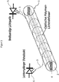
- FIG. 1 shows a schematic representation of an embodiment of a sensor element 1 of the sensor system according to the invention for monitoring pressure force and moisture changes on a textile substrate.
- the sensor element 1 according to the invention is formed with a strand-shaped elastic carrier material 2 and a polymer optical fiber 3 arranged on the carrier material 2, wherein the carrier material 2 and the polymer optical fiber 3 are interconnected by a core-shell method (KEMAFIL).
- KEMAFIL core-shell method
- the polymer optical fiber 3 is preferably wound spirally uniformly round the carrier material 2 which is round in cross-section, the windings of the polymer optical fiber 3 not crossing each other.
- the reference numeral 5 denotes a broadband light source, which is connected to the light coupling with one end of the polymer optical fiber 3 of the sensor element 1 via a plug connection.
- the polymer optical fiber 3 may preferably be formed in the core of polymethyl methacrylate, polyacrylate 6.6, or polypropylene.
- the polymer optical fiber 3 has no cladding to allow light extraction over the circumference.
- Reference numeral 6 denotes a detector element having a photodiode which is arranged to detect an intensity of the light guided through the polymer optical fiber 3.
- the other end of the polymer optical fiber 3 is connected to the detector element 6 by means of a plug connection.
- the carrier material 2 may be formed with a solid material or as a hose made of rubber or silicone. In addition, the carrier material 2 may have a further material 4 in the core. Explanations to various core materials of the sensor element 1 are with the comments on FIG. 2 specify.
- the sensor element 1 Due to the strand-shaped elastic shaping of the carrier material 2, the sensor element 1 fits flexibly into textile structures, so that Various arrangements can be selected to integrate the sensor element 1 in a textile pad. Thus, the sensor element 1 can be integrated by weaving in a textile pad.
- a component of the sensor system according to the invention is also an evaluation device (not shown), which is coupled to the detector element 6 in order to evaluate the light intensity signals supplied by the detector element 6.
- the evaluation device detects a time course of an intensity signal change and assigns a detected change in intensity of a change in humidity and / or a pressure force change.
- the sensor system according to the invention has an in FIG. 1 Notification device, likewise not shown, with which a detected or associated change in humidity and / or a pressure force change can be displayed.
- the notification device can have a display unit with which moisture events and / or pressure force events can be represented graphically.
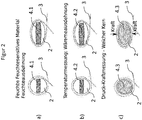
- FIG. 2 shows schematic representations of three training variants a, b and c of the sensor element 1 in each case in cross section.
- the polymer optical fiber 3 is wound around the strand-shaped elastic carrier material 2, the carrier material 2 each having an additional core material 4.1 to 4.3.
- the variant a shows a sensor element 1 in which in the core of the carrier material 2 a swellable at liquid contact core material 4.1 is arranged.
- liquid swelling of the core material 4.1 leads to a cross-sectional deformation of the arranged on the surface of the substrate 2 polymer optical fiber 3, whereby light is coupled over the circumference of the polymer optical fiber 3, which detected with the detector element 6 and is recognized by the evaluation device by means of a predetermined evaluation algorithm as a moisture event.
- a core material 4.2 is arranged in the core of the carrier material 2, which expands depending on temperature.
- an elongation of the core material 4.2 caused by a temperature change leads to a cross-sectional deformation of the polymer optical fiber 3 disposed on the surface of the substrate 2, whereby light is coupled out over the circumference of the polymer optical fiber 3, which is detected by the detector element 6 and detected by the Evaluation device is detected by means of a predetermined evaluation algorithm as a temperature change.
- an elastic core material 4.3 is arranged in the core of the carrier material 2.
- an expansion of the core material 4.3 caused by compressive force leads to a cross-sectional deformation of the polymer optical fiber 3 arranged on the surface of the substrate 2, whereby light is coupled out over the circumference of the polymer optical fiber 3, which is detected by the detector element 6 and by the evaluation device a predetermined evaluation algorithm is recognized as a pressure force change.
- the sensor element can be formed from various combinations of the above variants a, b and c, wherein combinations of a and c and b and c are preferred.
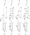
- FIGS. 3a to 3d show schematic representations of the sensor element 1 for explaining the operation of the sensor system according to the invention, wherein from left to right in each case a longitudinal view of the sensor element 1, an axial cross-section through the polymer optical fiber 3 and a course diagram 7.1, 7.2, 7.3 and 7.4 each with the detector element and the evaluation device detectable intensity of the guided through the polymer optical fiber 3 light are shown.
- Both Diagrams 7.1, 7.2, 7.3 and 7.4 show the light intensity signal in relation to time.
- the light from the broadband light source 5 is coupled into an end of the polymer optical fiber 3 of the sensor element 1 that can be integrated into a planar textile support and at the other end of the polymer optical fiber 3 to the detector element 6 an intensity of detected by the polymer optical fiber 3 light guided.
- the evaluation device With the evaluation device, the time profile of the intensity signals supplied by the decorative element 6 is detected and evaluated. If an intensity signal change is detected, it is assigned to a moisture event or a change in humidity and / or a pressure force change on the basis of its time course.
- FIG. 3a shows a representation of the sensor element 1 in a relieved of compressive force and dry state, so that, as can be seen from the schematic representation of the axial cross section of the polymer optical fiber 3, a total reflection of the injected into the polymer optical fiber 3 light is made possible. Accordingly, no change in the intensity signal is displayed in the diagram 7.1, so that no event notification is required.
- FIG. 3b shows a representation of the sensor element 1, wherein a pressure force F shown with arrows is exerted on the sensor element 1, so that the carrier material 2 and the arrangement of the polymer optical fiber 3 are deformed.
- the thereby caused cross-sectional deformation of the polymer optical fiber 3 causes a Lichtauskopplung 8 on the outer surface of the polymer optical fiber 3, as can be seen from the axial cross-sectional view of the polymer optical fiber 3.
- the compressive force events F on the sensor element in FIG Form of intensity signal changes 7.2.1, 7.2.2 and 7.2.3 shown. Due to their time course, the intensity changes 7.2.1, 7.2.2 and 7.2.3 can each be assigned pressure force changes.
- the evaluation device can detect a movement of a patient or a respiration or a respiratory frequency of the patient on the basis of the intensity profile shown in FIG.
- Figure 3c shows a representation of the sensor element 1, wherein a droplet with symbols 9 acting on the sensor element 1 is shown liquid.
- the liquid contact with the polymer optical fiber 3 leads to a change in the refractive index of the surrounding medium, so that it comes across the outer surface of the polymer optical fiber 3 to a light output 10, which is shown in the diagram 7.3 as a single occurring intensity change 7.3.1.
- 3d figure shows a representation of the sensor element 1, wherein a liquid acting on the sensor element 1 with droplet symbols 9 is shown and at the same time a pressure force F acts on the sensor element 1.
- the liquid contact and the cross-sectional deformation due to the application of pressure F cause light outcouplings 11 and 12, which are shown with different time profiles in the diagram 7.4.
- the intensity signal changes 7.4.1 and 7.4.3 are assigned to a pressure force change F on the basis of their short time interval, wherein the intensity signal change 7.4.2 can be assigned to a liquid contact or a moisture change on the basis of the once occurring and permanent signal.
- a moisture change and a change in pressure force can thus be detected with a sensor element 1.
- FIG. 4 shows a schematic representation of components of Sensor system according to the invention in an application for monitoring requirements of care and medical care of a patient.
- Reference symbol 13 shows the evaluation device into which a notification device 14 is integrated.
- a display unit 20 which is part of the notification device 14
- a history diagram 7 of an intensity signal is shown.
- patient information such as the name of a patient 15 and a status message 16 can be displayed with the display unit 20, the status message 16 indicating a moisture event and / or a patient movement event.
- the notification device is coupled via a wireless network 17 to a mobile terminal 18, via whose display 19 the patient information 15 and status messages 16 are displayed.
- a notification can be provided via the network 17 to a control center, wherein the notification can simultaneously trigger an emergency call. Furthermore, provision may be made for the notification device 14 to be coupled to an illumination system which is switched on in response to a pressure force change or moisture change determined by the evaluation device 13.
- the sensor system according to the invention in vehicles for fatigue detection. Integration and application possibilities for the sensor system according to the invention are also seen in connection with massage tables, crash mats, vehicle seats, patient transport means such as wheelchairs and sports mats.
- the sensor system is used in patient monitoring to record patient movement and humidity events. Based on patient movements, a respiratory rate and the risk of bedsores can be monitored and monitored in the form of a patient Status message to be transmitted centrally.
Landscapes
- Physics & Mathematics (AREA)
- General Physics & Mathematics (AREA)
- Measuring And Recording Apparatus For Diagnosis (AREA)
Applications Claiming Priority (1)
| Application Number | Priority Date | Filing Date | Title |
|---|---|---|---|
| DE102017105575 | 2017-03-15 |
Publications (2)
| Publication Number | Publication Date |
|---|---|
| EP3376170A1 true EP3376170A1 (fr) | 2018-09-19 |
| EP3376170B1 EP3376170B1 (fr) | 2021-06-16 |
Family
ID=61683634
Family Applications (1)
| Application Number | Title | Priority Date | Filing Date |
|---|---|---|---|
| EP18161952.9A Active EP3376170B1 (fr) | 2017-03-15 | 2018-03-15 | Système capteur destiné à la surveillance de force de pression et de changement d'humidité sur un support textile et procédé d'application dudit système capteur |
Country Status (1)
| Country | Link |
|---|---|
| EP (1) | EP3376170B1 (fr) |
Cited By (2)
| Publication number | Priority date | Publication date | Assignee | Title |
|---|---|---|---|---|
| WO2020078614A1 (fr) * | 2018-10-17 | 2020-04-23 | Robert Bosch Gmbh | Capteur à fibre optique et procédé pour reconnaître une contamination sur un textile, textile pourvu d'un capteur à fibre optique ainsi que contrôleur |
| CN112097799A (zh) * | 2020-08-25 | 2020-12-18 | 浙江清华柔性电子技术研究院 | 异质纤维传感器 |
Citations (5)
| Publication number | Priority date | Publication date | Assignee | Title |
|---|---|---|---|---|
| DE102004010437A1 (de) * | 2004-03-01 | 2005-09-22 | Georg-Simon-Ohm Fachhochschule Nürnberg, vertreten durch den Rektor | Optische Sensoreinrichtung |
| DE102006046778A1 (de) * | 2006-09-29 | 2008-04-03 | Siemens Ag | Faseroptische Sensorvorrichtung |
| DE102006048635A1 (de) * | 2006-10-13 | 2008-04-17 | Siemens Ag | Faseroptischer Biegesensor und Verfahren zu dessen Herstellung |
| EP2267204A1 (fr) * | 2009-06-26 | 2010-12-29 | Huesker Synthetic GmbH | Structure textile plate dotée d'une fibre conductrice de lumière intégrée |
| KR101439463B1 (ko) * | 2013-03-21 | 2014-09-17 | 전진홍 | 압력 검지 시스템 |
Family Cites Families (3)
| Publication number | Priority date | Publication date | Assignee | Title |
|---|---|---|---|---|
| DE3327158A1 (de) * | 1983-07-28 | 1985-02-07 | Licentia Patent-Verwaltungs-Gmbh, 6000 Frankfurt | Detektor bestehend aus einer lichtquelle, einem lichtempfaenger sowie mindestens einer dazwischen angeordneten faser |
| DE3817269A1 (de) * | 1988-05-20 | 1989-11-30 | Vdo Schindling | Optischer weggeber |
| DE4011440A1 (de) * | 1990-04-09 | 1991-10-10 | Reinshagen Kabelwerk Gmbh | Sensorelement, insbesondere sensorkabel |
-
2018
- 2018-03-15 EP EP18161952.9A patent/EP3376170B1/fr active Active
Patent Citations (5)
| Publication number | Priority date | Publication date | Assignee | Title |
|---|---|---|---|---|
| DE102004010437A1 (de) * | 2004-03-01 | 2005-09-22 | Georg-Simon-Ohm Fachhochschule Nürnberg, vertreten durch den Rektor | Optische Sensoreinrichtung |
| DE102006046778A1 (de) * | 2006-09-29 | 2008-04-03 | Siemens Ag | Faseroptische Sensorvorrichtung |
| DE102006048635A1 (de) * | 2006-10-13 | 2008-04-17 | Siemens Ag | Faseroptischer Biegesensor und Verfahren zu dessen Herstellung |
| EP2267204A1 (fr) * | 2009-06-26 | 2010-12-29 | Huesker Synthetic GmbH | Structure textile plate dotée d'une fibre conductrice de lumière intégrée |
| KR101439463B1 (ko) * | 2013-03-21 | 2014-09-17 | 전진홍 | 압력 검지 시스템 |
Cited By (3)
| Publication number | Priority date | Publication date | Assignee | Title |
|---|---|---|---|---|
| WO2020078614A1 (fr) * | 2018-10-17 | 2020-04-23 | Robert Bosch Gmbh | Capteur à fibre optique et procédé pour reconnaître une contamination sur un textile, textile pourvu d'un capteur à fibre optique ainsi que contrôleur |
| CN112097799A (zh) * | 2020-08-25 | 2020-12-18 | 浙江清华柔性电子技术研究院 | 异质纤维传感器 |
| CN112097799B (zh) * | 2020-08-25 | 2025-12-30 | 浙江清华柔性电子技术研究院 | 异质纤维传感器 |
Also Published As
| Publication number | Publication date |
|---|---|
| EP3376170B1 (fr) | 2021-06-16 |
Similar Documents
| Publication | Publication Date | Title |
|---|---|---|
| EP0573765B1 (fr) | Méthode et dispositif de surveillance de la variation d'état de mouvement des articles ou des parties du corps humain | |
| DE60022515T2 (de) | Vorrichtung zum wahrnehmen von harninkontinenz eines patienten | |
| DE69916428T2 (de) | Patientenbettüberwachung mit mikroprozessor | |
| WO1994022516A1 (fr) | Dispositif permettant la surveillance d'au moins un raccordement dans un systeme de tuyaux medical | |
| EP3376170A1 (fr) | Système capteur destiné à la surveillance de force de pression et de changement d'humidité sur un support textile et procédé d'application dudit système capteur | |
| EP3017283A1 (fr) | Dispositif de mesure d'une fonction corporelle | |
| DE102014103520B4 (de) | Medizinische Datenerfassungseinrichtung | |
| DE102013217094A1 (de) | Mikromechanisches Bauelement und entsprechendes Prüfverfahren für ein mikromechanisches Bauelement | |
| EP2626845B1 (fr) | Procédé et système de capteur pour la surveillance d'espace sensorielle | |
| DE202017102608U1 (de) | Vorrichtung zur Körperüberwachung | |
| DE102010042524B4 (de) | Tragbares Gerät mit Bedieneinheit | |
| DE102005006111A1 (de) | Verfahren zur Steuerung des Funktionsumfangs diagnostischer Vorrichtungen | |
| DE10058378C2 (de) | Vorrichtung zur Überwachung der Fluiddurchflußrate in einer Fluidleitung | |
| DE102015013572B4 (de) | Universelles Anschlusssystem für Sensoren und Verfahren zur Erkennung von Sensoren | |
| DE102012102850A1 (de) | Fluidfördervorrichtung und Fluidförderverfahren für medizinische Anwendungen | |
| DE102018116264B4 (de) | Lichtgitter | |
| EP1758064B1 (fr) | Système d'alarme à vibration pour signaler un incendie ou un danger | |
| EP2045682A1 (fr) | Dispositif d'automatisation doté d'une MTBF lisible | |
| DE3912141A1 (de) | Vorrichtung zur anzeige von druckbelastungen | |
| EP1929948A1 (fr) | Dispositif de perçage | |
| DE202024102791U1 (de) | System zur Beschränkung des Zugangs zu einem Gefahrenbereich um eine elektrische Test-Vorrichtung | |
| AT518046A1 (de) | Drucksensor, Messmatratze, Liegestatt, Verfahren und Diagnosesystem | |
| DE102004057811B4 (de) | Fahrtreppe oder Fahrsteig mit einem Steuerelement die mindestens einen Sicherheitskreis aufweist | |
| DE102016204554A1 (de) | Mobile Funktionseinheit zur Integration in ein Bekeidungsstück | |
| DE102014010906A1 (de) | Dialysegerät |
Legal Events
| Date | Code | Title | Description |
|---|---|---|---|
| PUAI | Public reference made under article 153(3) epc to a published international application that has entered the european phase |
Free format text: ORIGINAL CODE: 0009012 |
|
| STAA | Information on the status of an ep patent application or granted ep patent |
Free format text: STATUS: THE APPLICATION HAS BEEN PUBLISHED |
|
| AK | Designated contracting states |
Kind code of ref document: A1 Designated state(s): AL AT BE BG CH CY CZ DE DK EE ES FI FR GB GR HR HU IE IS IT LI LT LU LV MC MK MT NL NO PL PT RO RS SE SI SK SM TR |
|
| AX | Request for extension of the european patent |
Extension state: BA ME |
|
| STAA | Information on the status of an ep patent application or granted ep patent |
Free format text: STATUS: REQUEST FOR EXAMINATION WAS MADE |
|
| 17P | Request for examination filed |
Effective date: 20190312 |
|
| RBV | Designated contracting states (corrected) |
Designated state(s): AL AT BE BG CH CY CZ DE DK EE ES FI FR GB GR HR HU IE IS IT LI LT LU LV MC MK MT NL NO PL PT RO RS SE SI SK SM TR |
|
| STAA | Information on the status of an ep patent application or granted ep patent |
Free format text: STATUS: EXAMINATION IS IN PROGRESS |
|
| 17Q | First examination report despatched |
Effective date: 20200810 |
|
| GRAP | Despatch of communication of intention to grant a patent |
Free format text: ORIGINAL CODE: EPIDOSNIGR1 |
|
| STAA | Information on the status of an ep patent application or granted ep patent |
Free format text: STATUS: GRANT OF PATENT IS INTENDED |
|
| INTG | Intention to grant announced |
Effective date: 20210304 |
|
| GRAS | Grant fee paid |
Free format text: ORIGINAL CODE: EPIDOSNIGR3 |
|
| GRAA | (expected) grant |
Free format text: ORIGINAL CODE: 0009210 |
|
| STAA | Information on the status of an ep patent application or granted ep patent |
Free format text: STATUS: THE PATENT HAS BEEN GRANTED |
|
| AK | Designated contracting states |
Kind code of ref document: B1 Designated state(s): AL AT BE BG CH CY CZ DE DK EE ES FI FR GB GR HR HU IE IS IT LI LT LU LV MC MK MT NL NO PL PT RO RS SE SI SK SM TR |
|
| REG | Reference to a national code |
Ref country code: GB Ref legal event code: FG4D Free format text: NOT ENGLISH |
|
| REG | Reference to a national code |
Ref country code: CH Ref legal event code: EP |
|
| REG | Reference to a national code |
Ref country code: DE Ref legal event code: R096 Ref document number: 502018005702 Country of ref document: DE |
|
| REG | Reference to a national code |
Ref country code: AT Ref legal event code: REF Ref document number: 1402706 Country of ref document: AT Kind code of ref document: T Effective date: 20210715 |
|
| REG | Reference to a national code |
Ref country code: IE Ref legal event code: FG4D Free format text: LANGUAGE OF EP DOCUMENT: GERMAN |
|
| REG | Reference to a national code |
Ref country code: LT Ref legal event code: MG9D |
|
| PG25 | Lapsed in a contracting state [announced via postgrant information from national office to epo] |
Ref country code: FI Free format text: LAPSE BECAUSE OF FAILURE TO SUBMIT A TRANSLATION OF THE DESCRIPTION OR TO PAY THE FEE WITHIN THE PRESCRIBED TIME-LIMIT Effective date: 20210616 Ref country code: LT Free format text: LAPSE BECAUSE OF FAILURE TO SUBMIT A TRANSLATION OF THE DESCRIPTION OR TO PAY THE FEE WITHIN THE PRESCRIBED TIME-LIMIT Effective date: 20210616 Ref country code: HR Free format text: LAPSE BECAUSE OF FAILURE TO SUBMIT A TRANSLATION OF THE DESCRIPTION OR TO PAY THE FEE WITHIN THE PRESCRIBED TIME-LIMIT Effective date: 20210616 Ref country code: BG Free format text: LAPSE BECAUSE OF FAILURE TO SUBMIT A TRANSLATION OF THE DESCRIPTION OR TO PAY THE FEE WITHIN THE PRESCRIBED TIME-LIMIT Effective date: 20210916 |
|
| REG | Reference to a national code |
Ref country code: NL Ref legal event code: MP Effective date: 20210616 |
|
| PG25 | Lapsed in a contracting state [announced via postgrant information from national office to epo] |
Ref country code: GR Free format text: LAPSE BECAUSE OF FAILURE TO SUBMIT A TRANSLATION OF THE DESCRIPTION OR TO PAY THE FEE WITHIN THE PRESCRIBED TIME-LIMIT Effective date: 20210917 Ref country code: NO Free format text: LAPSE BECAUSE OF FAILURE TO SUBMIT A TRANSLATION OF THE DESCRIPTION OR TO PAY THE FEE WITHIN THE PRESCRIBED TIME-LIMIT Effective date: 20210916 Ref country code: LV Free format text: LAPSE BECAUSE OF FAILURE TO SUBMIT A TRANSLATION OF THE DESCRIPTION OR TO PAY THE FEE WITHIN THE PRESCRIBED TIME-LIMIT Effective date: 20210616 Ref country code: SE Free format text: LAPSE BECAUSE OF FAILURE TO SUBMIT A TRANSLATION OF THE DESCRIPTION OR TO PAY THE FEE WITHIN THE PRESCRIBED TIME-LIMIT Effective date: 20210616 Ref country code: RS Free format text: LAPSE BECAUSE OF FAILURE TO SUBMIT A TRANSLATION OF THE DESCRIPTION OR TO PAY THE FEE WITHIN THE PRESCRIBED TIME-LIMIT Effective date: 20210616 |
|
| PG25 | Lapsed in a contracting state [announced via postgrant information from national office to epo] |
Ref country code: CZ Free format text: LAPSE BECAUSE OF FAILURE TO SUBMIT A TRANSLATION OF THE DESCRIPTION OR TO PAY THE FEE WITHIN THE PRESCRIBED TIME-LIMIT Effective date: 20210616 Ref country code: RO Free format text: LAPSE BECAUSE OF FAILURE TO SUBMIT A TRANSLATION OF THE DESCRIPTION OR TO PAY THE FEE WITHIN THE PRESCRIBED TIME-LIMIT Effective date: 20210616 Ref country code: NL Free format text: LAPSE BECAUSE OF FAILURE TO SUBMIT A TRANSLATION OF THE DESCRIPTION OR TO PAY THE FEE WITHIN THE PRESCRIBED TIME-LIMIT Effective date: 20210616 Ref country code: PT Free format text: LAPSE BECAUSE OF FAILURE TO SUBMIT A TRANSLATION OF THE DESCRIPTION OR TO PAY THE FEE WITHIN THE PRESCRIBED TIME-LIMIT Effective date: 20211018 Ref country code: EE Free format text: LAPSE BECAUSE OF FAILURE TO SUBMIT A TRANSLATION OF THE DESCRIPTION OR TO PAY THE FEE WITHIN THE PRESCRIBED TIME-LIMIT Effective date: 20210616 Ref country code: ES Free format text: LAPSE BECAUSE OF FAILURE TO SUBMIT A TRANSLATION OF THE DESCRIPTION OR TO PAY THE FEE WITHIN THE PRESCRIBED TIME-LIMIT Effective date: 20210616 Ref country code: SM Free format text: LAPSE BECAUSE OF FAILURE TO SUBMIT A TRANSLATION OF THE DESCRIPTION OR TO PAY THE FEE WITHIN THE PRESCRIBED TIME-LIMIT Effective date: 20210616 Ref country code: SK Free format text: LAPSE BECAUSE OF FAILURE TO SUBMIT A TRANSLATION OF THE DESCRIPTION OR TO PAY THE FEE WITHIN THE PRESCRIBED TIME-LIMIT Effective date: 20210616 |
|
| PG25 | Lapsed in a contracting state [announced via postgrant information from national office to epo] |
Ref country code: PL Free format text: LAPSE BECAUSE OF FAILURE TO SUBMIT A TRANSLATION OF THE DESCRIPTION OR TO PAY THE FEE WITHIN THE PRESCRIBED TIME-LIMIT Effective date: 20210616 |
|
| REG | Reference to a national code |
Ref country code: DE Ref legal event code: R097 Ref document number: 502018005702 Country of ref document: DE |
|
| PLBE | No opposition filed within time limit |
Free format text: ORIGINAL CODE: 0009261 |
|
| STAA | Information on the status of an ep patent application or granted ep patent |
Free format text: STATUS: NO OPPOSITION FILED WITHIN TIME LIMIT |
|
| PG25 | Lapsed in a contracting state [announced via postgrant information from national office to epo] |
Ref country code: DK Free format text: LAPSE BECAUSE OF FAILURE TO SUBMIT A TRANSLATION OF THE DESCRIPTION OR TO PAY THE FEE WITHIN THE PRESCRIBED TIME-LIMIT Effective date: 20210616 |
|
| PGFP | Annual fee paid to national office [announced via postgrant information from national office to epo] |
Ref country code: GB Payment date: 20220324 Year of fee payment: 5 Ref country code: DE Payment date: 20220322 Year of fee payment: 5 Ref country code: CH Payment date: 20220324 Year of fee payment: 5 |
|
| 26N | No opposition filed |
Effective date: 20220317 |
|
| PG25 | Lapsed in a contracting state [announced via postgrant information from national office to epo] |
Ref country code: AL Free format text: LAPSE BECAUSE OF FAILURE TO SUBMIT A TRANSLATION OF THE DESCRIPTION OR TO PAY THE FEE WITHIN THE PRESCRIBED TIME-LIMIT Effective date: 20210616 |
|
| PGFP | Annual fee paid to national office [announced via postgrant information from national office to epo] |
Ref country code: FR Payment date: 20220322 Year of fee payment: 5 |
|
| PG25 | Lapsed in a contracting state [announced via postgrant information from national office to epo] |
Ref country code: IT Free format text: LAPSE BECAUSE OF FAILURE TO SUBMIT A TRANSLATION OF THE DESCRIPTION OR TO PAY THE FEE WITHIN THE PRESCRIBED TIME-LIMIT Effective date: 20210616 |
|
| PG25 | Lapsed in a contracting state [announced via postgrant information from national office to epo] |
Ref country code: MC Free format text: LAPSE BECAUSE OF FAILURE TO SUBMIT A TRANSLATION OF THE DESCRIPTION OR TO PAY THE FEE WITHIN THE PRESCRIBED TIME-LIMIT Effective date: 20210616 |
|
| REG | Reference to a national code |
Ref country code: BE Ref legal event code: MM Effective date: 20220331 |
|
| PG25 | Lapsed in a contracting state [announced via postgrant information from national office to epo] |
Ref country code: LU Free format text: LAPSE BECAUSE OF NON-PAYMENT OF DUE FEES Effective date: 20220315 Ref country code: IE Free format text: LAPSE BECAUSE OF NON-PAYMENT OF DUE FEES Effective date: 20220315 |
|
| PG25 | Lapsed in a contracting state [announced via postgrant information from national office to epo] |
Ref country code: BE Free format text: LAPSE BECAUSE OF NON-PAYMENT OF DUE FEES Effective date: 20220331 |
|
| REG | Reference to a national code |
Ref country code: DE Ref legal event code: R119 Ref document number: 502018005702 Country of ref document: DE |
|
| REG | Reference to a national code |
Ref country code: CH Ref legal event code: PL |
|
| GBPC | Gb: european patent ceased through non-payment of renewal fee |
Effective date: 20230315 |
|
| PG25 | Lapsed in a contracting state [announced via postgrant information from national office to epo] |
Ref country code: GB Free format text: LAPSE BECAUSE OF NON-PAYMENT OF DUE FEES Effective date: 20230315 |
|
| PG25 | Lapsed in a contracting state [announced via postgrant information from national office to epo] |
Ref country code: LI Free format text: LAPSE BECAUSE OF NON-PAYMENT OF DUE FEES Effective date: 20230331 Ref country code: GB Free format text: LAPSE BECAUSE OF NON-PAYMENT OF DUE FEES Effective date: 20230315 Ref country code: FR Free format text: LAPSE BECAUSE OF NON-PAYMENT OF DUE FEES Effective date: 20230331 Ref country code: DE Free format text: LAPSE BECAUSE OF NON-PAYMENT OF DUE FEES Effective date: 20231003 Ref country code: CH Free format text: LAPSE BECAUSE OF NON-PAYMENT OF DUE FEES Effective date: 20230331 |
|
| PG25 | Lapsed in a contracting state [announced via postgrant information from national office to epo] |
Ref country code: HU Free format text: LAPSE BECAUSE OF FAILURE TO SUBMIT A TRANSLATION OF THE DESCRIPTION OR TO PAY THE FEE WITHIN THE PRESCRIBED TIME-LIMIT; INVALID AB INITIO Effective date: 20180315 |
|
| PG25 | Lapsed in a contracting state [announced via postgrant information from national office to epo] |
Ref country code: MK Free format text: LAPSE BECAUSE OF FAILURE TO SUBMIT A TRANSLATION OF THE DESCRIPTION OR TO PAY THE FEE WITHIN THE PRESCRIBED TIME-LIMIT Effective date: 20210616 Ref country code: CY Free format text: LAPSE BECAUSE OF FAILURE TO SUBMIT A TRANSLATION OF THE DESCRIPTION OR TO PAY THE FEE WITHIN THE PRESCRIBED TIME-LIMIT Effective date: 20210616 |
|
| REG | Reference to a national code |
Ref country code: AT Ref legal event code: MM01 Ref document number: 1402706 Country of ref document: AT Kind code of ref document: T Effective date: 20230315 |
|
| PG25 | Lapsed in a contracting state [announced via postgrant information from national office to epo] |
Ref country code: TR Free format text: LAPSE BECAUSE OF FAILURE TO SUBMIT A TRANSLATION OF THE DESCRIPTION OR TO PAY THE FEE WITHIN THE PRESCRIBED TIME-LIMIT Effective date: 20210616 |
|
| PG25 | Lapsed in a contracting state [announced via postgrant information from national office to epo] |
Ref country code: AT Free format text: LAPSE BECAUSE OF NON-PAYMENT OF DUE FEES Effective date: 20230315 |
|
| PG25 | Lapsed in a contracting state [announced via postgrant information from national office to epo] |
Ref country code: AT Free format text: LAPSE BECAUSE OF NON-PAYMENT OF DUE FEES Effective date: 20230315 |
|
| PG25 | Lapsed in a contracting state [announced via postgrant information from national office to epo] |
Ref country code: MT Free format text: LAPSE BECAUSE OF FAILURE TO SUBMIT A TRANSLATION OF THE DESCRIPTION OR TO PAY THE FEE WITHIN THE PRESCRIBED TIME-LIMIT Effective date: 20210616 |
|
| PGFP | Annual fee paid to national office [announced via postgrant information from national office to epo] |
Ref country code: AT Payment date: 20260410 Year of fee payment: 5 |