EP3376170B1 - Système capteur destiné à la surveillance de force de pression et de changement d'humidité sur un support textile et procédé d'application dudit système capteur - Google Patents
Système capteur destiné à la surveillance de force de pression et de changement d'humidité sur un support textile et procédé d'application dudit système capteur Download PDFInfo
- Publication number
- EP3376170B1 EP3376170B1 EP18161952.9A EP18161952A EP3376170B1 EP 3376170 B1 EP3376170 B1 EP 3376170B1 EP 18161952 A EP18161952 A EP 18161952A EP 3376170 B1 EP3376170 B1 EP 3376170B1
- Authority
- EP
- European Patent Office
- Prior art keywords
- light
- sensor system
- change
- polymeroptic
- patient
- Prior art date
- Legal status (The legal status is an assumption and is not a legal conclusion. Google has not performed a legal analysis and makes no representation as to the accuracy of the status listed.)
- Active
Links
Images


Classifications
-
- G—PHYSICS
- G01—MEASURING; TESTING
- G01D—MEASURING NOT SPECIALLY ADAPTED FOR A SPECIFIC VARIABLE; ARRANGEMENTS FOR MEASURING TWO OR MORE VARIABLES NOT COVERED IN A SINGLE OTHER SUBCLASS; TARIFF METERING APPARATUS; MEASURING OR TESTING NOT OTHERWISE PROVIDED FOR
- G01D5/00—Mechanical means for transferring the output of a sensing member; Means for converting the output of a sensing member to another variable where the form or nature of the sensing member does not constrain the means for converting; Transducers not specially adapted for a specific variable
- G01D5/26—Mechanical means for transferring the output of a sensing member; Means for converting the output of a sensing member to another variable where the form or nature of the sensing member does not constrain the means for converting; Transducers not specially adapted for a specific variable characterised by optical transfer means, i.e. using infrared, visible, or ultraviolet light
- G01D5/32—Mechanical means for transferring the output of a sensing member; Means for converting the output of a sensing member to another variable where the form or nature of the sensing member does not constrain the means for converting; Transducers not specially adapted for a specific variable characterised by optical transfer means, i.e. using infrared, visible, or ultraviolet light with attenuation or whole or partial obturation of beams of light
- G01D5/34—Mechanical means for transferring the output of a sensing member; Means for converting the output of a sensing member to another variable where the form or nature of the sensing member does not constrain the means for converting; Transducers not specially adapted for a specific variable characterised by optical transfer means, i.e. using infrared, visible, or ultraviolet light with attenuation or whole or partial obturation of beams of light the beams of light being detected by photocells
- G01D5/353—Mechanical means for transferring the output of a sensing member; Means for converting the output of a sensing member to another variable where the form or nature of the sensing member does not constrain the means for converting; Transducers not specially adapted for a specific variable characterised by optical transfer means, i.e. using infrared, visible, or ultraviolet light with attenuation or whole or partial obturation of beams of light the beams of light being detected by photocells influencing the transmission properties of an optical fibre
- G01D5/3537—Optical fibre sensor using a particular arrangement of the optical fibre itself
- G01D5/3538—Optical fibre sensor using a particular arrangement of the optical fibre itself using a particular type of fiber, e.g. fibre with several cores, PANDA fiber, fiber with an elliptic core or the like
-
- G—PHYSICS
- G01—MEASURING; TESTING
- G01D—MEASURING NOT SPECIALLY ADAPTED FOR A SPECIFIC VARIABLE; ARRANGEMENTS FOR MEASURING TWO OR MORE VARIABLES NOT COVERED IN A SINGLE OTHER SUBCLASS; TARIFF METERING APPARATUS; MEASURING OR TESTING NOT OTHERWISE PROVIDED FOR
- G01D5/00—Mechanical means for transferring the output of a sensing member; Means for converting the output of a sensing member to another variable where the form or nature of the sensing member does not constrain the means for converting; Transducers not specially adapted for a specific variable
- G01D5/26—Mechanical means for transferring the output of a sensing member; Means for converting the output of a sensing member to another variable where the form or nature of the sensing member does not constrain the means for converting; Transducers not specially adapted for a specific variable characterised by optical transfer means, i.e. using infrared, visible, or ultraviolet light
- G01D5/32—Mechanical means for transferring the output of a sensing member; Means for converting the output of a sensing member to another variable where the form or nature of the sensing member does not constrain the means for converting; Transducers not specially adapted for a specific variable characterised by optical transfer means, i.e. using infrared, visible, or ultraviolet light with attenuation or whole or partial obturation of beams of light
- G01D5/34—Mechanical means for transferring the output of a sensing member; Means for converting the output of a sensing member to another variable where the form or nature of the sensing member does not constrain the means for converting; Transducers not specially adapted for a specific variable characterised by optical transfer means, i.e. using infrared, visible, or ultraviolet light with attenuation or whole or partial obturation of beams of light the beams of light being detected by photocells
- G01D5/353—Mechanical means for transferring the output of a sensing member; Means for converting the output of a sensing member to another variable where the form or nature of the sensing member does not constrain the means for converting; Transducers not specially adapted for a specific variable characterised by optical transfer means, i.e. using infrared, visible, or ultraviolet light with attenuation or whole or partial obturation of beams of light the beams of light being detected by photocells influencing the transmission properties of an optical fibre
- G01D5/35338—Mechanical means for transferring the output of a sensing member; Means for converting the output of a sensing member to another variable where the form or nature of the sensing member does not constrain the means for converting; Transducers not specially adapted for a specific variable characterised by optical transfer means, i.e. using infrared, visible, or ultraviolet light with attenuation or whole or partial obturation of beams of light the beams of light being detected by photocells influencing the transmission properties of an optical fibre using other arrangements than interferometer arrangements
- G01D5/35341—Sensor working in transmission
- G01D5/35345—Sensor working in transmission using Amplitude variations to detect the measured quantity
Definitions
- the invention relates to a sensor system for monitoring pressure force and moisture changes on a textile base and a method for using the sensor system, in particular for monitoring the needs of the care and medical care of a patient.
- Sensor systems for monitoring changes in pressure and moisture on a surface are used in various areas of technology.
- Pressure force sensors or moisture sensors are used, for example, in the field of care to facilitate patient monitoring and to support the work of the staff.
- the previously known sensor solutions which are usually based on electrical sensors or on glass fiber optic sensors, prove to be disadvantageous for various applications, in particular in the care sector.
- electrical sensors for example, there is the problem of susceptibility to interference from other electrical devices in the vicinity, so that complex shielding of electrical conductors is necessary in each case.
- Another problem is that electrical signals react sensitively to moisture, so that complex plug-in connections must be provided in order to be able to avoid the ingress of moisture.
- different sensor systems usually have to be used to determine changes in pressure force and moisture, which means the expense of a sensory Monitoring system also increased.
- the complex connection technology proves to be disadvantageous, since splicing and fusing of the glass fibers, which are only 5 ⁇ m to 9 ⁇ m thick in the light core, is necessary for the connection.
- a fiber optic measuring system such as a fiber Bragg grating sensor system, is comparatively cost-intensive.
- KR 101 439 463 B1 which has a plurality of optical fibers.
- a plurality of first optical fiber optics are arranged in parallel, in one plane, spaced apart from one another, and several second optical fibers are positioned perpendicular thereto, likewise spaced apart from one another.
- the first and the second optical fibers thus form a net-like mat of optical fibers into which light can be coupled from the ends of the optical fibers.
- the system also has detectors that convert the optical signals into electrical signals so that they can then be passed on and evaluated.
- the pressure detection system described is essentially based on the fact that a pressure deforms the optical fibers, as a result of which the optical properties of the optical fibers are changed. Because of this, the amount of coupled-out light changes with the pressure exerted, and changes in pressure can thus be detected. Furthermore, a pressure distribution can also be determined with such a device on the basis of the two-dimensional alignment of the optical fibers.
- An optical sensor device which has a curved optical waveguide, is in the DE 10 2004 010437 A1 described.
- the curvature of the optical waveguide results from winding the optical waveguide around an elongated carrier element. Since the optical waveguide is wound evenly, a mode equilibrium and the resulting coupling-out behavior are established. With one acting on the carrier element Pressure leads to an at least section-wise change in the winding radius of the optical waveguide, which has a significant influence on the optical properties of the optical waveguide and the modes that develop in the optical waveguide. As a result, conclusions can be drawn about the pressure acting on the basis of the light that is coupled out.
- DE 3327158 A1 discloses an optical detector with an optical fiber for detecting a temperature and / or air humidity due to mechanical stresses due to volume changes in a body in which the optical fiber is embedded in a measurement area.
- the known sensor systems also have the disadvantage that rapid and uncomplicated exchangeability or cleaning is not possible or is only possible with increased effort.
- cleaning or washing components with electrical contacts special precautions must be taken to prevent the ingress of moisture.
- fiber optic sensor systems a complex connection technology prevents simple and quick interchangeability of sensor components.
- the sensor system according to the invention for monitoring pressure force and moisture changes on a textile base has a sensor element formed with a strand-like elastic carrier material and a polymer optical fiber arranged on the carrier material, which sensor element is intended for integration into a textile base. Due to the strand-like elastic carrier material, the sensor element can be easily integrated into textile structures. Furthermore, the sensor system according to the invention has a broadband light source and a detector element, the light source for coupling in light being connected to one end of the polymer optical fiber of the sensor element and the detector element being connected to the other end of the polymer optical fiber for detecting an intensity signal of the light guided through the polymer optical fiber is.
- a component of the sensor system according to the invention is also an evaluation device with which at least a change in humidity and / or a change in pressure force can be assigned to a time curve of an intensity signal supplied by the detector element.
- a notification device is also provided for displaying the change in humidity and / or the change in pressure force.
- a base is to be understood as a flat textile structure which is used separately in one piece or as a component of a multi-part structure and is used to place it under an object or a person.
- a mattress, an upholstered piece of furniture or a cover for a mattress or a piece of furniture can therefore also be seen as a base to be understood in the context of the invention.
- the solution according to the invention is based on a light-based sensor principle, in which at least one moisture or one Pressure force is exploited that light reflections of the light coupled into the polymer optical fiber by the light source change in the event of liquid contact and / or in the event of a cross-sectional deformation due to the action of force, such as for example by bending, within the polymer optical optical fiber, whereby the light signal intensity that can be detected by the detector element changes .
- a compressive load on the sensor element causes a deformation of the cross-section of the polymer optical fiber, with light being coupled out over the circumference of the polymer optical fiber, which can be detected as a change in the intensity signal.
- the surrounding medium changes at the interface of the polymer optical fiber, which results in permanent light decoupling over the circumference of the polymer optical fiber.
- the time courses of intensity signal changes are differentiated and assigned to at least one pressure force change or a change in humidity.
- a polymer optical fiber In order to be able to ensure that light is coupled out in the event of contact with liquid or in the event of cross-sectional deformation, a polymer optical fiber is used that has no fiber cladding or an interrupted fiber cladding.
- a temporal course of an intensity signal change caused by a liquid contact with the sensor element and / or a cross-sectional deformation of the sensor element can be detected, a change in humidity and / or a pressure force change being recognizable on the basis of a temporal course of a change in intensity.
- Different algorithms or filters can be used to evaluate the course of changes in the intensity signal over time. Recurring or irregular intensity signal changes with short time intervals are considered movements identifiable. A change in intensity signal that occurs only once in time can be identified as a change in moisture or as a moisture event. Due to the distinguishability of the temporal progressions of an intensity signal change caused by compressive force stress and an intensity signal change caused by contact with liquid, moisture changes and compressive force changes can be determined simultaneously with one sensor element.
- connection of the polymer optical fiber with the detector element or the light source can be realized by comparatively simple plug connections due to the light guide core, which is usually larger than 0.25 mm, which ensures easy integration and exchangeability of the system.
- a plug connection of the polymer optical fiber can be implemented by cutting and fixing in a plug without the need for complex connection technology. Because the plug-in connection of the polymer optical fiber can be easily detached, a base with the sensor element integrated therein can be easily separated from the detector element or the evaluation device and cleaned or washed separately.
- Another advantage is that due to the lack of electrical components in the sensor element, no electromagnetic fields are generated which could cause interference with other electrical devices such as active implants, pacemakers, nerve stimulators, drug pumps or hearing prostheses.
- the elastic, strand-like carrier material is sufficiently flexible to integrate the sensor element in various arrangements in a textile base.
- the sensor element can therefore be in a meandering or spiral arrangement with the formation of a Total reflection of the light coupled into the polymer optical fiber can be integrated.
- the polymer-optical optical fiber can be wound around the strand-like elastic carrier material, the polymer-optical optical fiber being arranged in a spiral on the surface of the elastic, strand-like carrier material.
- the strand-like elastic carrier material of the sensor element has a material that swells when it comes into contact with a liquid.
- a swellable nonwoven structure for example, can be used as the swellable material, which is connected to the polymer optical fiber as a carrier material in a core-sheath process (KEMAFIL).
- KEMAFIL core-sheath process
- a moisture event can be determined on the basis of a compressive force on the polymer optical fiber and the associated cross-sectional deformation of the polymer optical fiber, caused by the liquid swelling of the carrier material, since a change in the intensity signal can be detected on the detector element due to the cross-sectional deformation of the polymer optical fiber.
- the strand-like elastic carrier material can have a temperature-dependent expandable material.
- a temperature change can be determined on the basis of a compressive force on the polymer optical fiber caused by the temperature-dependent expansion of the carrier material and the associated cross-sectional deformation of the polymer optical fiber, since a change in the intensity signal can be detected on the detector element due to the cross-sectional deformation of the polymer optical fiber. Criteria for differentiating the signals are, for example, cyclical change in the signals through which the signals are after Humidity and temperature can be distinguished. Furthermore, a step response to changes in humidity can be measured as well as to long-term temperature changes. With motion detection, the signal changes are in the range of seconds.
- the core of the polymer optical optical fiber can preferably be formed from polymethyl methacrylate, polyacrylate 6.6, or polypropylene.
- the polymer optical optical fiber has no cladding or an interrupted cladding made from a fluoropolymer.
- the elastic, strand-like carrier material determines the shape of the sensor element. Due to the strand-like elastic shape, the sensor element fits well into textile structures.
- the sensor element can preferably be woven into a textile base.
- the carrier material can, for example, contain a rubber or a silicone or be formed entirely from a rubber or a silicone. Furthermore, the carrier material can be formed with a solid material or as a tube. A circular cross section of the elastic, strand-like carrier material is preferred.
- the carrier material and the polymer optical optical fiber can preferably be connected to one another by a core-cladding process (KEMAFIL).
- the notification device is connected to a wireless network for information transmission. Furthermore, it can be provided that the notification device can be coupled to a further technical device, wherein the further technical device can be switched on in response to a change in humidity and / or a change in pressure force.
- the idea is to provide a lighting device and / or an emergency call device as a further technical device in order to access to draw attention to a change in humidity and / or a change in pressure.
- the notification device can be designed as a display unit or have a display unit.
- the display unit is used to display the course over time of the intensities of the light guided through the polymer optical fiber, ascertained with the detector element.
- the display unit can also be provided for the graphic or visual representation of a detected change in humidity and / or a detected change in pressure force.
- the notification device can be coupled to a mobile display device, so that a change in pressure force and / or a change in humidity can be transmitted to the mobile display device for display.
- the light source, the detector element, the evaluation device and the notification device can be accommodated on a common circuit board.
- the electronic and optoelectronic elements thus form a unit that can be separated from the sensor element, which has an advantageous effect on the handling of the sensor system according to the invention.
- the sensor system according to the invention enables changes in pressure force and changes in moisture to be determined on a base, which makes the sensor system particularly suitable for monitoring the needs of nursing and medical care of a patient.
- a method is therefore also proposed for using the sensor system according to the invention for monitoring the needs of nursing and medical care of a patient.
- the light from a light source is directed into one end of the polymer optical fiber in a flat textile
- the strand-like sensor element integrated into the patient pad is coupled in and at the other end of the polymer optical fiber, at least one change in the intensity signal, based on a cross-sectional deformation of the sensor element, of the light guided through the polymer optical fiber is detected with the detector element, a detected change in the intensity signal based on its At least one moisture event and / or a patient movement event is / are allocated over the course of time, an allocated moisture event and / or an allocated patient movement event being displayed with the notification device.
- recurring intensity signal changes with a short time interval can be assigned to a patient movement of a patient lying on the patient pad.
- recurring intensity signal changes with a short time interval can also be assigned to a breathing rate of a patient lying on the patient pad, so that the sensor system according to the invention can be used to monitor the breathing of a patient. It is also intended to recognize irregularities in a respiratory rate and, if necessary, to indicate a medical care requirement.
- a lack of exercise can be recognized in order to prevent a risk of bed sores for a patient.
- the notification device can be used to display a corresponding notification of the need for long-term care.
- a moisture event on the patient pad is determined as a result of a cross-sectional deformation of the polymer optical optical fiber caused by a liquid swelling of the sensor element.
- a Moisture event can in turn be indicated as a care requirement with the notification device.
- a temperature change on the patient pad as a result of a cross-sectional deformation of the polymer optical fiber caused by expansion of the carrier material is determined.
- an emergency call can be triggered after a predefinable time. It can further be provided that the emergency call is triggered after a predeterminable time if a return of a patient cannot be determined on the patient pad.
- Status reports relating to a moisture event, a patient movement event and / or a change in temperature can be transmitted via a wireless network for display to a central or mobile display unit, thereby ensuring remote monitoring.
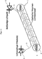
- Figure 1 shows a schematic representation of an exemplary embodiment of a sensor element 1 of the sensor system according to the invention for monitoring changes in pressure force and moisture on a textile base.
- the sensor element 1 according to the invention is formed with a strand-like elastic carrier material 2 and a polymer optical fiber 3 arranged on the carrier material 2, the carrier material 2 and the polymer optical fiber 3 being connected to one another by a core-sheath process (KEMAFIL).
- KEMAFIL core-sheath process
- the polymer optical optical fiber 3 is preferably wound in a spiral shape around the carrier material 2, which is round in cross section, the windings of the polymer optical optical fiber 3 not crossing one another.
- the reference number 5 denotes a broadband light source which, for coupling in light, is connected to one end of the polymer optical fiber 3 of the sensor element 1 via a plug connection.
- the core of the polymer optical optical fiber 3 can preferably be formed from polymethyl methacrylate, polyacrylate 6.6, or polypropylene.
- the polymer optical optical fiber 3 preferably does not have a cladding in order to enable light to be coupled out over the circumference.
- the reference number 6 denotes a detector element with a photodiode which is set up to detect an intensity of the light guided through the polymer optical fiber 3.
- the other end of the polymer optical fiber 3 is connected to the detector element 6 by means of a plug connection.
- the carrier material 2 can be made from a solid material or as a tube Rubber or silicone.
- the carrier material 2 can have a further material 4 in the core. Explanations of various core materials of the sensor element 1 are to be found in the explanations for Figure 2 specify.
- the sensor element 1 can be flexibly inserted into textile structures, so that different arrangements can be selected in order to integrate the sensor element 1 into a textile base.
- the sensor element 1 can thus be integrated into a textile base by being woven into it.
- a component of the sensor system according to the invention is also an evaluation device (not shown) which is coupled to the detector element 6 in order to evaluate the light intensity signals supplied by the detector element 6.
- the evaluation device detects a time profile of an intensity signal change and assigns a change in humidity and / or a change in pressure force to a detected change in intensity signal.
- the sensor system according to the invention has an in Figure 1 notification device, also not shown, with which a recognized or assigned change in humidity and / or a change in pressure force can be displayed.
- the notification device can have a display unit with which moisture events and / or compressive force events can be represented graphically.
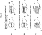
- Figure 2 shows schematic representations of three further development variants a, b and c of the sensor element 1, each in cross section.
- the polymer optical optical fiber 3 is wound around the strand-like elastic carrier material 2, the carrier material 2 each having an additional core material 4.1 to 4.3.
- Variant a shows a sensor element 1 in which a core material 4.1, which swells on contact with liquid, is arranged in the core of the carrier material 2.
- a core material 4.1 which swells on contact with liquid
- the carrier material 2 is arranged in the core of the carrier material 2.
- At Variant a leads to a liquid swelling of the core material 4.1 caused by liquid contact with the sensor element 1 to a cross-sectional deformation of the polymer optical fiber 3 arranged on the surface of the carrier material 2, whereby light is coupled out over the circumference of the polymer optical fiber 3, which is detected with the detector element 6 and with the evaluation device is recognized as a moisture event by means of a predetermined evaluation algorithm.
- a core material 4.2 which expands as a function of temperature, is arranged in the core of the carrier material 2.
- an expansion of the core material 4.2 caused by a change in temperature leads to a cross-sectional deformation of the polymer optical fiber 3 arranged on the surface of the carrier material 2, whereby light is coupled out over the circumference of the polymer optical fiber 3, which is detected with the detector element 6 and with the Evaluation device is recognized as a temperature change by means of a predetermined evaluation algorithm.
- an elastic core material 4.3 is arranged in the core of the carrier material 2.
- an expansion of the core material 4.3 caused by compressive force leads to a cross-sectional deformation of the polymer optical fiber 3 arranged on the surface of the carrier material 2, whereby light is coupled out over the circumference of the polymer optical fiber 3, which is detected with the detector element 6 and with the evaluation device by means of a predetermined evaluation algorithm is recognized as a pressure force change.
- the sensor element can be formed from various combinations of the above variants a, b and c, combinations of a and c and b and c being preferred.
- FIGS. 3a to 3d show schematic representations of the sensor element 1 to explain the functioning of the sensor system according to the invention, with a longitudinal view of the sensor element 1, an axial cross-section through the polymer optical fiber 3 and a progression diagram 7.1, 7.2, 7.3 and 7.4 each with the detector element 6 from left to right and the intensity of the light guided through the polymer optical fiber 3 that can be detected by the evaluation device is shown.
- the signal of the light intensity is shown in relation to time.
- the light of the broadband light source 5 is coupled into one end of the polymer optical fiber 3 of the sensor element 1 that can be integrated into a flat textile base and at the other end of the polymer optical fiber 3 with the detector element 6 an intensity of the detected by the polymer optical fiber 3 guided light.
- the time course of the intensity signals supplied by the decorative element 6 is recorded and evaluated with the evaluation device. If a change in the intensity signal is detected, it is assigned to a moisture event or a change in moisture and / or a change in pressure force on the basis of its course over time.
- Figure 3a shows a representation of the sensor element 1 in a dry state relieved of compressive force, so that, as can be seen from the schematic representation of the axial cross section of the polymer optical fiber 3, a total reflection of the light coupled into the polymer optical fiber 3 is made possible. Accordingly, no change in the intensity signal is displayed in diagram 7.1, so that no event notification is required either.
- Figure 3b shows a representation of the sensor element 1, one with arrows compressive force F shown is exerted on the sensor element 1, so that the carrier material 2 and the arrangement of the polymer optical fiber 3 are deformed.
- the resulting cross-sectional deformation of the polymer optical fiber 3 causes light to be coupled out 8 via the outer surface of the polymer optical fiber 3, as can be seen from the axial cross-section of the polymer optical fiber 3.
- the pressure force events F on the sensor element are shown in the form of intensity signal changes 7.2.1, 7.2.2 and 7.2.3.
- the changes in intensity 7.2.1, 7.2.2 and 7.2.3 can each be assigned to changes in pressure force on the basis of their course over time.
- the evaluation device can use the intensity profile shown in diagram 7.2 to detect a movement of a patient or a breathing or a breathing frequency of the patient.
- Figure 3c shows a representation of the sensor element 1, wherein a liquid acting on the sensor element 1 with drop symbols 9 is shown.
- the liquid contact with the polymer optical fiber 3 leads to a change in the refractive index of the surrounding medium, so that a light decoupling 10 occurs via the outer surface of the polymer optical fiber 3, which is shown in diagram 7.3 as a one-time change in intensity 7.3.1.
- Figure 3d shows a representation of the sensor element 1, with a liquid acting on the sensor element 1 with drop symbols 9 and at the same time a compressive force F acting on the sensor element 1.
- the contact with the liquid and the cross-sectional deformation caused by the action of the pressure force F cause light decoupling 11 and 12, which are shown with different time courses in diagram 7.4.
- the intensity signal changes 7.4.1 and 7.4.3 are to be assigned to a pressure force change F based on their short time interval, with the Intensity signal change 7.4.2 can be assigned to a liquid contact or a change in humidity due to the one-time and permanent signal. A change in humidity and a change in pressure force can thus advantageously be detected with a sensor element 1.
- FIG. 4 shows a schematic representation of components of the sensor system according to the invention in an application for monitoring the needs of nursing and medical care of a patient.
- the evaluation device in which a notification device 14 is integrated, is shown with the reference numeral 13.
- a progression diagram 7 of an intensity signal is shown by means of a display unit 20, which is part of the notification device 14.
- patient information such as the name of a patient 15 and a status message 16 can be displayed with the display unit 20, the status message 16 indicating a moisture event and / or a patient movement event.
- the notification device is coupled via a wireless network 17 to a mobile terminal 18, via the display 19 of which the patient information 15 and status messages 16 are displayed.
- a notification can be provided via the network 17 to a control center, the notification being able to trigger an emergency call at the same time. Furthermore, it can be provided that the notification device 14 is coupled to a lighting system which is switched on in response to a change in pressure force or a change in humidity determined with the evaluation device 13.
- the sensor system according to the invention is intended to use in vehicles for drowsiness detection. Integration and application possibilities for the sensor system according to the invention are also in connection with Massage tables, fall mats, vehicle seats, patient transport equipment such as wheelchairs and sports mats were seen.
- the sensor system In nursing, the sensor system is used in patient monitoring to record patient movements and moisture events. On the basis of patient movements, a breathing rate and the risk of bed sores can be monitored and centrally transmitted in the form of a status report.
Landscapes
- Physics & Mathematics (AREA)
- General Physics & Mathematics (AREA)
- Measuring And Recording Apparatus For Diagnosis (AREA)
Claims (20)
- Système de capteurs pour la surveillance de modifications de pression et d'humidité sur une base textile, présentant
un élément de capteur (1) formé d'un matériau support (2) élastique en forme de boyau et d'une fibre optique polymère (3) disposée sur le matériau support (2) pour l'intégration dans une base textile, dans lequel la fibre optique polymère ne présente aucune enveloppe de fibre ou une enveloppe de fibre interrompue,
une source lumineuse (5) qui est connectée à une extrémité de la fibre optique polymère (3) pour l'injection lumineuse,
un élément de détecteur (6) qui est connecté à l'autre extrémité de la fibre optique polymère (3) pour la détection d'un signal d'intensité de la lumière conduite par la fibre optique polymère (3),
un dispositif d'évaluation (13) qui est configuré pour identifier à l'aide des tracés temporels des modifications de signal d'intensité du signal d'intensité livré par l'élément de détecteur (6) au moins une modification d'humidité et/ou une modification de pression, et
un dispositif de notification (14) pour l'affichage de la modification d'humidité et/ou de la modification de pression. - Système de capteurs selon la revendication 1, caractérisé en ce que l'élément de capteur (1) peut être intégré en réalisant une réflexion totale de la lumière injectée dans la fibre optique polymère (3) dans une base textile.
- Système de capteurs selon une des revendications 1 ou 2, caractérisé en ce que la fibre optique polymère (3) est enroulée autour du matériau support (2) élastique en forme de boyau.
- Système de capteurs selon une des revendications 1 à 3, caractérisé en ce que le matériau support (2) élastique en forme de boyau présente un matériau (4.1) pouvant gonfler en cas de contact avec un liquide.
- Système de capteurs selon une des revendications 1 à 4, caractérisé en ce que le matériau support (2) élastique en forme de boyau présente un matériau (4.2) pouvant être dilaté en fonction de la température, dans lequel une modification de signal d'intensité peut être identifiée en tant que modification de température.
- Système de capteurs selon une des revendications 1 à 5, caractérisé en ce que la fibre optique polymère (3) est formée dans le noyau de polyméthacrylate de méthyle, polyacrylate 6.6 ou polypropylène.
- Système de capteurs selon une des revendications 1 à 6, caractérisé en ce que l'élément de capteur (1) peut être entrelacé dans une base textile.
- Système de capteurs selon une des revendications 1 à 7, caractérisé en ce que des modifications de signal d'intensité récurrentes ou irrégulières peuvent être identifiées en tant que mouvements.
- Système de capteurs selon une des revendications 1 à 8, caractérisé en ce qu'une modification de signal d'intensité survenant une fois dans le temps peut être identifiée en tant que modification d'humidité.
- Système de capteurs selon une des revendications 1 à 9, caractérisé en ce que le dispositif de notification peut être couplé à un autre dispositif technique, dans lequel l'autre dispositif technique peut être allumé en tant que réaction à une modification d'humidité et/ou une modification de pression.
- Système de capteurs selon la revendication 10, caractérisé en ce que le dispositif de notification peut être couplé à l'autre dispositif technique par le biais d'un réseau sans fil.
- Système de capteurs selon une des revendications 1 à 11, caractérisé en ce que la fibre optique polymère (3) est connectée à la source lumineuse (5) et à l'élément de détecteur (6) au moyen de fiches de raccordement.
- Système de capteurs selon une des revendications 1 à 12, caractérisé en ce que la source lumineuse (5), l'élément de détecteur (6), le dispositif d'évaluation (13) et le dispositif de notification (14) sont hébergés sur une carte imprimée commune.
- Procédé d'utilisation du système de capteurs selon les revendications 1 à 13 pour la surveillance des exigences en soins et assistance médicale d'un patient, lors duquel la lumière de la source lumineuse (5) est injectée dans une extrémité de la fibre optique polymère (3) de l'élément de capteur (1) en forme de boyau intégré dans une alèse textile plane et une modification de signal d'intensité par un contact avec un liquide avec l'élément de capteur et/ou reposant sur une déformation de section transversale de l'élément de capteur de la lumière conduite par la fibre optique polymère (3) est détectée avec l'élément de détecteur (6) à l'autre extrémité de la fibre optique polymère (3), et des tracés temporels de modifications de signal d'intensité sont distingués, dans lequel au moins un événement d'humidité et/ou un événement de mouvement du patient est/sont associé(s) à une modification de signal d'intensité détectée à l'aide de son tracé temporel, dans lequel l'événement d'humidité associé et/ou l'événement de mouvement du patient associé est/sont affiché(s) avec le dispositif de notification.
- Procédé selon la revendication 14, caractérisé en ce qu'un événement d'humidité sur l'alèse est déterminé à la suite d'une déformation de section transversale de la fibre optique polymère (3) provoquée par un gonflement de liquide de l'élément de capteur (1).
- Procédé selon la revendication 14 ou 15, caractérisé en ce qu'un changement de température sur l'alèse est déterminé à la suite d'une déformation de section transversale de la fibre optique polymère (3) provoquée par une dilatation d'un matériau support (2, 4.2).
- Procédé selon une des revendications 14 à 16, caractérisé en ce que des modifications de signal d'intensité récurrentes (7.2.1, 7.2.2, 7.2.3, 7.4.1, 7.4.3) sont associées à un intervalle de temps court d'une fréquence respiratoire d'un patient.
- Procédé selon une des revendications 14 à 17, caractérisé en ce qu'une modification de signal d'intensité persistante de manière unique (7.3.1 ; 7.4.2) est associée à un événement d'humidité sur l'alèse.
- Procédé selon une des revendications 14 à 18, caractérisé en ce qu'un abandon de l'alèse est détecté à l'aide d'un événement de mouvement du patient, dans lequel un abandon de l'alèse entraîne un allumage d'éléments d'éclairage et/ou déclenche un appel d'urgence après une durée pouvant être prédéfinie.
- Procédé selon une des revendications 14 à 19, caractérisé en ce qu'un événement d'humidité, un événement de mouvement du patient et/ou un changement de température sont transmis pour l'affichage à un module d'affichage mobile (19) par le biais d'un réseau sans fil.
Applications Claiming Priority (1)
| Application Number | Priority Date | Filing Date | Title |
|---|---|---|---|
| DE102017105575 | 2017-03-15 |
Publications (2)
| Publication Number | Publication Date |
|---|---|
| EP3376170A1 EP3376170A1 (fr) | 2018-09-19 |
| EP3376170B1 true EP3376170B1 (fr) | 2021-06-16 |
Family
ID=61683634
Family Applications (1)
| Application Number | Title | Priority Date | Filing Date |
|---|---|---|---|
| EP18161952.9A Active EP3376170B1 (fr) | 2017-03-15 | 2018-03-15 | Système capteur destiné à la surveillance de force de pression et de changement d'humidité sur un support textile et procédé d'application dudit système capteur |
Country Status (1)
| Country | Link |
|---|---|
| EP (1) | EP3376170B1 (fr) |
Families Citing this family (2)
| Publication number | Priority date | Publication date | Assignee | Title |
|---|---|---|---|---|
| DE102018217733A1 (de) * | 2018-10-17 | 2020-04-23 | Robert Bosch Gmbh | Faseroptischer Sensor und Verfahren zum Erkennen einer Verunreinigung an einem Textil, Textil mit einem faseroptischen Sensor sowie Steuergerät |
| CN112097799B (zh) * | 2020-08-25 | 2025-12-30 | 浙江清华柔性电子技术研究院 | 异质纤维传感器 |
Citations (3)
| Publication number | Priority date | Publication date | Assignee | Title |
|---|---|---|---|---|
| DE3327158A1 (de) * | 1983-07-28 | 1985-02-07 | Licentia Patent-Verwaltungs-Gmbh, 6000 Frankfurt | Detektor bestehend aus einer lichtquelle, einem lichtempfaenger sowie mindestens einer dazwischen angeordneten faser |
| DE3817269A1 (de) * | 1988-05-20 | 1989-11-30 | Vdo Schindling | Optischer weggeber |
| DE4011440A1 (de) * | 1990-04-09 | 1991-10-10 | Reinshagen Kabelwerk Gmbh | Sensorelement, insbesondere sensorkabel |
Family Cites Families (5)
| Publication number | Priority date | Publication date | Assignee | Title |
|---|---|---|---|---|
| DE102004010437A1 (de) * | 2004-03-01 | 2005-09-22 | Georg-Simon-Ohm Fachhochschule Nürnberg, vertreten durch den Rektor | Optische Sensoreinrichtung |
| DE102006046778A1 (de) * | 2006-09-29 | 2008-04-03 | Siemens Ag | Faseroptische Sensorvorrichtung |
| DE102006048635B4 (de) * | 2006-10-13 | 2009-03-19 | Continental Automotive Gmbh | Faseroptischer Biegesensor und Verfahren zu dessen Herstellung |
| DE102009027254A1 (de) * | 2009-06-26 | 2011-01-05 | Huesker Synthetic Gmbh | Textiles Flächengebilde mit integrierter Lichtleitfaser |
| KR101439463B1 (ko) * | 2013-03-21 | 2014-09-17 | 전진홍 | 압력 검지 시스템 |
-
2018
- 2018-03-15 EP EP18161952.9A patent/EP3376170B1/fr active Active
Patent Citations (3)
| Publication number | Priority date | Publication date | Assignee | Title |
|---|---|---|---|---|
| DE3327158A1 (de) * | 1983-07-28 | 1985-02-07 | Licentia Patent-Verwaltungs-Gmbh, 6000 Frankfurt | Detektor bestehend aus einer lichtquelle, einem lichtempfaenger sowie mindestens einer dazwischen angeordneten faser |
| DE3817269A1 (de) * | 1988-05-20 | 1989-11-30 | Vdo Schindling | Optischer weggeber |
| DE4011440A1 (de) * | 1990-04-09 | 1991-10-10 | Reinshagen Kabelwerk Gmbh | Sensorelement, insbesondere sensorkabel |
Also Published As
| Publication number | Publication date |
|---|---|
| EP3376170A1 (fr) | 2018-09-19 |
Similar Documents
| Publication | Publication Date | Title |
|---|---|---|
| EP0573765B1 (fr) | Méthode et dispositif de surveillance de la variation d'état de mouvement des articles ou des parties du corps humain | |
| EP3376170B1 (fr) | Système capteur destiné à la surveillance de force de pression et de changement d'humidité sur un support textile et procédé d'application dudit système capteur | |
| DE102018131925A1 (de) | Taktiler Sensor und Androide | |
| EP2877420A2 (fr) | Escalator ou tapis roulant | |
| EP3748536A1 (fr) | Système et procédé de détection automatique de situations dangereuses | |
| DE102008004523A1 (de) | Vorrichtung zur nicht-invasiven, dynamischen Messung der Brustkorbaktivität einer Person | |
| EP3765119B1 (fr) | Dispositif de surveillance d'un accès vasculaire en cours d'un traitement extracorporel du sang | |
| EP2934242B1 (fr) | Procédé de surveillance d'un appareil de cuisson et appareil de cuisson pourvu d'un capteur de température | |
| DE102008011142B4 (de) | Überwachungssystem | |
| DE102015101608B4 (de) | Verfahren zur Signalweiterleitung, Vorrichtung mit einer optischen Faser und Detektionssystem | |
| EP2220996B1 (fr) | Indicateur de pression pour pansements compressifs médicaux | |
| EP3384262A2 (fr) | Capteur de pression, matelas de mesure, couchette, procédé et système de diagnostic | |
| DE3912141A1 (de) | Vorrichtung zur anzeige von druckbelastungen | |
| DE3940006C2 (fr) | ||
| EP2626845B1 (fr) | Procédé et système de capteur pour la surveillance d'espace sensorielle | |
| WO1997021165A1 (fr) | Procede et dispositif de commutation et/ou de commande au moyen d'un ordinateur | |
| EP2592604B1 (fr) | Système de surveillance et procédé de commande d'un système de surveillance pour un poste médical de soins intensifs | |
| EP3171909B1 (fr) | Appareil de dialyse | |
| AT518046B1 (de) | Drucksensor, Messmatratze, Liegestatt, Verfahren und Diagnosesystem | |
| DE10316255A1 (de) | Ausdehnungserfassungsvorrichtung | |
| DE202017102608U1 (de) | Vorrichtung zur Körperüberwachung | |
| DE202013101920U1 (de) | Hygieneartikel, sowie System zur Zustandsüberwachung hiervon | |
| DE102016111261A1 (de) | Drucksensor, Messmatratze, Liegestatt, Verfahren und Diagnosesystem | |
| EP1758064A2 (fr) | Système d'alarme à vibration pour signaler un incendie ou un danger | |
| DE102012102850A1 (de) | Fluidfördervorrichtung und Fluidförderverfahren für medizinische Anwendungen |
Legal Events
| Date | Code | Title | Description |
|---|---|---|---|
| PUAI | Public reference made under article 153(3) epc to a published international application that has entered the european phase |
Free format text: ORIGINAL CODE: 0009012 |
|
| STAA | Information on the status of an ep patent application or granted ep patent |
Free format text: STATUS: THE APPLICATION HAS BEEN PUBLISHED |
|
| AK | Designated contracting states |
Kind code of ref document: A1 Designated state(s): AL AT BE BG CH CY CZ DE DK EE ES FI FR GB GR HR HU IE IS IT LI LT LU LV MC MK MT NL NO PL PT RO RS SE SI SK SM TR |
|
| AX | Request for extension of the european patent |
Extension state: BA ME |
|
| STAA | Information on the status of an ep patent application or granted ep patent |
Free format text: STATUS: REQUEST FOR EXAMINATION WAS MADE |
|
| 17P | Request for examination filed |
Effective date: 20190312 |
|
| RBV | Designated contracting states (corrected) |
Designated state(s): AL AT BE BG CH CY CZ DE DK EE ES FI FR GB GR HR HU IE IS IT LI LT LU LV MC MK MT NL NO PL PT RO RS SE SI SK SM TR |
|
| STAA | Information on the status of an ep patent application or granted ep patent |
Free format text: STATUS: EXAMINATION IS IN PROGRESS |
|
| 17Q | First examination report despatched |
Effective date: 20200810 |
|
| GRAP | Despatch of communication of intention to grant a patent |
Free format text: ORIGINAL CODE: EPIDOSNIGR1 |
|
| STAA | Information on the status of an ep patent application or granted ep patent |
Free format text: STATUS: GRANT OF PATENT IS INTENDED |
|
| INTG | Intention to grant announced |
Effective date: 20210304 |
|
| GRAS | Grant fee paid |
Free format text: ORIGINAL CODE: EPIDOSNIGR3 |
|
| GRAA | (expected) grant |
Free format text: ORIGINAL CODE: 0009210 |
|
| STAA | Information on the status of an ep patent application or granted ep patent |
Free format text: STATUS: THE PATENT HAS BEEN GRANTED |
|
| AK | Designated contracting states |
Kind code of ref document: B1 Designated state(s): AL AT BE BG CH CY CZ DE DK EE ES FI FR GB GR HR HU IE IS IT LI LT LU LV MC MK MT NL NO PL PT RO RS SE SI SK SM TR |
|
| REG | Reference to a national code |
Ref country code: GB Ref legal event code: FG4D Free format text: NOT ENGLISH |
|
| REG | Reference to a national code |
Ref country code: CH Ref legal event code: EP |
|
| REG | Reference to a national code |
Ref country code: DE Ref legal event code: R096 Ref document number: 502018005702 Country of ref document: DE |
|
| REG | Reference to a national code |
Ref country code: AT Ref legal event code: REF Ref document number: 1402706 Country of ref document: AT Kind code of ref document: T Effective date: 20210715 |
|
| REG | Reference to a national code |
Ref country code: IE Ref legal event code: FG4D Free format text: LANGUAGE OF EP DOCUMENT: GERMAN |
|
| REG | Reference to a national code |
Ref country code: LT Ref legal event code: MG9D |
|
| PG25 | Lapsed in a contracting state [announced via postgrant information from national office to epo] |
Ref country code: FI Free format text: LAPSE BECAUSE OF FAILURE TO SUBMIT A TRANSLATION OF THE DESCRIPTION OR TO PAY THE FEE WITHIN THE PRESCRIBED TIME-LIMIT Effective date: 20210616 Ref country code: LT Free format text: LAPSE BECAUSE OF FAILURE TO SUBMIT A TRANSLATION OF THE DESCRIPTION OR TO PAY THE FEE WITHIN THE PRESCRIBED TIME-LIMIT Effective date: 20210616 Ref country code: HR Free format text: LAPSE BECAUSE OF FAILURE TO SUBMIT A TRANSLATION OF THE DESCRIPTION OR TO PAY THE FEE WITHIN THE PRESCRIBED TIME-LIMIT Effective date: 20210616 Ref country code: BG Free format text: LAPSE BECAUSE OF FAILURE TO SUBMIT A TRANSLATION OF THE DESCRIPTION OR TO PAY THE FEE WITHIN THE PRESCRIBED TIME-LIMIT Effective date: 20210916 |
|
| REG | Reference to a national code |
Ref country code: NL Ref legal event code: MP Effective date: 20210616 |
|
| PG25 | Lapsed in a contracting state [announced via postgrant information from national office to epo] |
Ref country code: GR Free format text: LAPSE BECAUSE OF FAILURE TO SUBMIT A TRANSLATION OF THE DESCRIPTION OR TO PAY THE FEE WITHIN THE PRESCRIBED TIME-LIMIT Effective date: 20210917 Ref country code: NO Free format text: LAPSE BECAUSE OF FAILURE TO SUBMIT A TRANSLATION OF THE DESCRIPTION OR TO PAY THE FEE WITHIN THE PRESCRIBED TIME-LIMIT Effective date: 20210916 Ref country code: LV Free format text: LAPSE BECAUSE OF FAILURE TO SUBMIT A TRANSLATION OF THE DESCRIPTION OR TO PAY THE FEE WITHIN THE PRESCRIBED TIME-LIMIT Effective date: 20210616 Ref country code: SE Free format text: LAPSE BECAUSE OF FAILURE TO SUBMIT A TRANSLATION OF THE DESCRIPTION OR TO PAY THE FEE WITHIN THE PRESCRIBED TIME-LIMIT Effective date: 20210616 Ref country code: RS Free format text: LAPSE BECAUSE OF FAILURE TO SUBMIT A TRANSLATION OF THE DESCRIPTION OR TO PAY THE FEE WITHIN THE PRESCRIBED TIME-LIMIT Effective date: 20210616 |
|
| PG25 | Lapsed in a contracting state [announced via postgrant information from national office to epo] |
Ref country code: CZ Free format text: LAPSE BECAUSE OF FAILURE TO SUBMIT A TRANSLATION OF THE DESCRIPTION OR TO PAY THE FEE WITHIN THE PRESCRIBED TIME-LIMIT Effective date: 20210616 Ref country code: RO Free format text: LAPSE BECAUSE OF FAILURE TO SUBMIT A TRANSLATION OF THE DESCRIPTION OR TO PAY THE FEE WITHIN THE PRESCRIBED TIME-LIMIT Effective date: 20210616 Ref country code: NL Free format text: LAPSE BECAUSE OF FAILURE TO SUBMIT A TRANSLATION OF THE DESCRIPTION OR TO PAY THE FEE WITHIN THE PRESCRIBED TIME-LIMIT Effective date: 20210616 Ref country code: PT Free format text: LAPSE BECAUSE OF FAILURE TO SUBMIT A TRANSLATION OF THE DESCRIPTION OR TO PAY THE FEE WITHIN THE PRESCRIBED TIME-LIMIT Effective date: 20211018 Ref country code: EE Free format text: LAPSE BECAUSE OF FAILURE TO SUBMIT A TRANSLATION OF THE DESCRIPTION OR TO PAY THE FEE WITHIN THE PRESCRIBED TIME-LIMIT Effective date: 20210616 Ref country code: ES Free format text: LAPSE BECAUSE OF FAILURE TO SUBMIT A TRANSLATION OF THE DESCRIPTION OR TO PAY THE FEE WITHIN THE PRESCRIBED TIME-LIMIT Effective date: 20210616 Ref country code: SM Free format text: LAPSE BECAUSE OF FAILURE TO SUBMIT A TRANSLATION OF THE DESCRIPTION OR TO PAY THE FEE WITHIN THE PRESCRIBED TIME-LIMIT Effective date: 20210616 Ref country code: SK Free format text: LAPSE BECAUSE OF FAILURE TO SUBMIT A TRANSLATION OF THE DESCRIPTION OR TO PAY THE FEE WITHIN THE PRESCRIBED TIME-LIMIT Effective date: 20210616 |
|
| PG25 | Lapsed in a contracting state [announced via postgrant information from national office to epo] |
Ref country code: PL Free format text: LAPSE BECAUSE OF FAILURE TO SUBMIT A TRANSLATION OF THE DESCRIPTION OR TO PAY THE FEE WITHIN THE PRESCRIBED TIME-LIMIT Effective date: 20210616 |
|
| REG | Reference to a national code |
Ref country code: DE Ref legal event code: R097 Ref document number: 502018005702 Country of ref document: DE |
|
| PLBE | No opposition filed within time limit |
Free format text: ORIGINAL CODE: 0009261 |
|
| STAA | Information on the status of an ep patent application or granted ep patent |
Free format text: STATUS: NO OPPOSITION FILED WITHIN TIME LIMIT |
|
| PG25 | Lapsed in a contracting state [announced via postgrant information from national office to epo] |
Ref country code: DK Free format text: LAPSE BECAUSE OF FAILURE TO SUBMIT A TRANSLATION OF THE DESCRIPTION OR TO PAY THE FEE WITHIN THE PRESCRIBED TIME-LIMIT Effective date: 20210616 |
|
| PGFP | Annual fee paid to national office [announced via postgrant information from national office to epo] |
Ref country code: GB Payment date: 20220324 Year of fee payment: 5 Ref country code: DE Payment date: 20220322 Year of fee payment: 5 Ref country code: CH Payment date: 20220324 Year of fee payment: 5 |
|
| 26N | No opposition filed |
Effective date: 20220317 |
|
| PG25 | Lapsed in a contracting state [announced via postgrant information from national office to epo] |
Ref country code: AL Free format text: LAPSE BECAUSE OF FAILURE TO SUBMIT A TRANSLATION OF THE DESCRIPTION OR TO PAY THE FEE WITHIN THE PRESCRIBED TIME-LIMIT Effective date: 20210616 |
|
| PGFP | Annual fee paid to national office [announced via postgrant information from national office to epo] |
Ref country code: FR Payment date: 20220322 Year of fee payment: 5 |
|
| PG25 | Lapsed in a contracting state [announced via postgrant information from national office to epo] |
Ref country code: IT Free format text: LAPSE BECAUSE OF FAILURE TO SUBMIT A TRANSLATION OF THE DESCRIPTION OR TO PAY THE FEE WITHIN THE PRESCRIBED TIME-LIMIT Effective date: 20210616 |
|
| PG25 | Lapsed in a contracting state [announced via postgrant information from national office to epo] |
Ref country code: MC Free format text: LAPSE BECAUSE OF FAILURE TO SUBMIT A TRANSLATION OF THE DESCRIPTION OR TO PAY THE FEE WITHIN THE PRESCRIBED TIME-LIMIT Effective date: 20210616 |
|
| REG | Reference to a national code |
Ref country code: BE Ref legal event code: MM Effective date: 20220331 |
|
| PG25 | Lapsed in a contracting state [announced via postgrant information from national office to epo] |
Ref country code: LU Free format text: LAPSE BECAUSE OF NON-PAYMENT OF DUE FEES Effective date: 20220315 Ref country code: IE Free format text: LAPSE BECAUSE OF NON-PAYMENT OF DUE FEES Effective date: 20220315 |
|
| PG25 | Lapsed in a contracting state [announced via postgrant information from national office to epo] |
Ref country code: BE Free format text: LAPSE BECAUSE OF NON-PAYMENT OF DUE FEES Effective date: 20220331 |
|
| REG | Reference to a national code |
Ref country code: DE Ref legal event code: R119 Ref document number: 502018005702 Country of ref document: DE |
|
| REG | Reference to a national code |
Ref country code: CH Ref legal event code: PL |
|
| GBPC | Gb: european patent ceased through non-payment of renewal fee |
Effective date: 20230315 |
|
| PG25 | Lapsed in a contracting state [announced via postgrant information from national office to epo] |
Ref country code: GB Free format text: LAPSE BECAUSE OF NON-PAYMENT OF DUE FEES Effective date: 20230315 |
|
| PG25 | Lapsed in a contracting state [announced via postgrant information from national office to epo] |
Ref country code: LI Free format text: LAPSE BECAUSE OF NON-PAYMENT OF DUE FEES Effective date: 20230331 Ref country code: GB Free format text: LAPSE BECAUSE OF NON-PAYMENT OF DUE FEES Effective date: 20230315 Ref country code: FR Free format text: LAPSE BECAUSE OF NON-PAYMENT OF DUE FEES Effective date: 20230331 Ref country code: DE Free format text: LAPSE BECAUSE OF NON-PAYMENT OF DUE FEES Effective date: 20231003 Ref country code: CH Free format text: LAPSE BECAUSE OF NON-PAYMENT OF DUE FEES Effective date: 20230331 |
|
| PG25 | Lapsed in a contracting state [announced via postgrant information from national office to epo] |
Ref country code: HU Free format text: LAPSE BECAUSE OF FAILURE TO SUBMIT A TRANSLATION OF THE DESCRIPTION OR TO PAY THE FEE WITHIN THE PRESCRIBED TIME-LIMIT; INVALID AB INITIO Effective date: 20180315 |
|
| PG25 | Lapsed in a contracting state [announced via postgrant information from national office to epo] |
Ref country code: MK Free format text: LAPSE BECAUSE OF FAILURE TO SUBMIT A TRANSLATION OF THE DESCRIPTION OR TO PAY THE FEE WITHIN THE PRESCRIBED TIME-LIMIT Effective date: 20210616 Ref country code: CY Free format text: LAPSE BECAUSE OF FAILURE TO SUBMIT A TRANSLATION OF THE DESCRIPTION OR TO PAY THE FEE WITHIN THE PRESCRIBED TIME-LIMIT Effective date: 20210616 |
|
| REG | Reference to a national code |
Ref country code: AT Ref legal event code: MM01 Ref document number: 1402706 Country of ref document: AT Kind code of ref document: T Effective date: 20230315 |
|
| PG25 | Lapsed in a contracting state [announced via postgrant information from national office to epo] |
Ref country code: TR Free format text: LAPSE BECAUSE OF FAILURE TO SUBMIT A TRANSLATION OF THE DESCRIPTION OR TO PAY THE FEE WITHIN THE PRESCRIBED TIME-LIMIT Effective date: 20210616 |
|
| PG25 | Lapsed in a contracting state [announced via postgrant information from national office to epo] |
Ref country code: AT Free format text: LAPSE BECAUSE OF NON-PAYMENT OF DUE FEES Effective date: 20230315 |
|
| PG25 | Lapsed in a contracting state [announced via postgrant information from national office to epo] |
Ref country code: AT Free format text: LAPSE BECAUSE OF NON-PAYMENT OF DUE FEES Effective date: 20230315 |
|
| PG25 | Lapsed in a contracting state [announced via postgrant information from national office to epo] |
Ref country code: MT Free format text: LAPSE BECAUSE OF FAILURE TO SUBMIT A TRANSLATION OF THE DESCRIPTION OR TO PAY THE FEE WITHIN THE PRESCRIBED TIME-LIMIT Effective date: 20210616 |
|
| PGFP | Annual fee paid to national office [announced via postgrant information from national office to epo] |
Ref country code: AT Payment date: 20260410 Year of fee payment: 5 |