EP4067832A1 - Débitmètre électromagnétique comportant une pluralité de bobines - Google Patents
Débitmètre électromagnétique comportant une pluralité de bobines Download PDFInfo
- Publication number
- EP4067832A1 EP4067832A1 EP21166163.2A EP21166163A EP4067832A1 EP 4067832 A1 EP4067832 A1 EP 4067832A1 EP 21166163 A EP21166163 A EP 21166163A EP 4067832 A1 EP4067832 A1 EP 4067832A1
- Authority
- EP
- European Patent Office
- Prior art keywords
- coils
- magnetic field
- pair
- electromagnetic flowmeter
- pairs
- Prior art date
- Legal status (The legal status is an assumption and is not a legal conclusion. Google has not performed a legal analysis and makes no representation as to the accuracy of the status listed.)
- Withdrawn
Links
Images



Classifications
-
- G—PHYSICS
- G01—MEASURING; TESTING
- G01F—MEASURING VOLUME, VOLUME FLOW, MASS FLOW OR LIQUID LEVEL; METERING BY VOLUME
- G01F1/00—Measuring the volume flow or mass flow of fluid or fluent solid material wherein the fluid passes through a meter in a continuous flow
- G01F1/56—Measuring the volume flow or mass flow of fluid or fluent solid material wherein the fluid passes through a meter in a continuous flow by using electric or magnetic effects
- G01F1/58—Measuring the volume flow or mass flow of fluid or fluent solid material wherein the fluid passes through a meter in a continuous flow by using electric or magnetic effects by electromagnetic flowmeters
- G01F1/586—Measuring the volume flow or mass flow of fluid or fluent solid material wherein the fluid passes through a meter in a continuous flow by using electric or magnetic effects by electromagnetic flowmeters constructions of coils, magnetic circuits, accessories therefor
-
- G—PHYSICS
- G01—MEASURING; TESTING
- G01F—MEASURING VOLUME, VOLUME FLOW, MASS FLOW OR LIQUID LEVEL; METERING BY VOLUME
- G01F1/00—Measuring the volume flow or mass flow of fluid or fluent solid material wherein the fluid passes through a meter in a continuous flow
- G01F1/56—Measuring the volume flow or mass flow of fluid or fluent solid material wherein the fluid passes through a meter in a continuous flow by using electric or magnetic effects
- G01F1/58—Measuring the volume flow or mass flow of fluid or fluent solid material wherein the fluid passes through a meter in a continuous flow by using electric or magnetic effects by electromagnetic flowmeters
- G01F1/588—Measuring the volume flow or mass flow of fluid or fluent solid material wherein the fluid passes through a meter in a continuous flow by using electric or magnetic effects by electromagnetic flowmeters combined constructions of electrodes, coils or magnetic circuits, accessories therefor
-
- G—PHYSICS
- G01—MEASURING; TESTING
- G01F—MEASURING VOLUME, VOLUME FLOW, MASS FLOW OR LIQUID LEVEL; METERING BY VOLUME
- G01F1/00—Measuring the volume flow or mass flow of fluid or fluent solid material wherein the fluid passes through a meter in a continuous flow
- G01F1/56—Measuring the volume flow or mass flow of fluid or fluent solid material wherein the fluid passes through a meter in a continuous flow by using electric or magnetic effects
- G01F1/58—Measuring the volume flow or mass flow of fluid or fluent solid material wherein the fluid passes through a meter in a continuous flow by using electric or magnetic effects by electromagnetic flowmeters
- G01F1/60—Circuits therefor
Definitions
- Electromagnetic flowmeters also referred to as magnetic-inductive flowmeters
- a magnetic field is generated by the electromagnetic flowmeter, perpendicular to the flow direction, and accordingly due to the interaction between the magnetic field and the conductive fluid flowing, a voltage perpendicular to the magnetic field and to the flow direction is generated and which is then measured by means of electrodes (known as measuring electrodes). Accordingly, based on the magnitude of the voltage generated, the velocity and volume of the fluid flowing is determined.
- the current disclosure relates to electromagnetic flowmeters.
- electromagnetic flowmeters measure volumetric flow of fluid by applying a magnetic field perpendicular to the flow of the fluid. Accordingly, to generate the magnetic field, the electromagnetic flowmeter includes a plurality of electromagnetic coils which when excited (by applying a current to them), generate the magnetic field.
- Electromagnetic flowmeters can be used along with pipes of various sizes including large diameter pipes. For large diameter electromagnetic flowmeters, coils have to be of special construction, to ensure the generated magnetic field is spread across the diameter of a measuring section of the electromagnetic flowmeter.
- the current disclosure describes an electromagnetic flowmeter capable of being installed on a fluid carrying channel for measuring a volumetric flow of a fluid flowing within the fluid carrying channel.
- the electromagnetic flowmeter comprises a measuring section configured for flow of the fluid through the electromagnetic flowmeter, a plurality of pairs of coils installed on the circumference of the measuring section, and a transmitter for exciting the plurality pairs of coils by providing one or more driving currents.
- the plurality of pairs of coils comprises a first pair of coils capable of generating a first magnetic field within the measuring section, and a second pair of coils capable of generating a second magnetic field within the measuring section.
- the first and second pairs of coils from the plurality of pairs of coils are installed along a first plane of the measuring section, the first plane perpendicular to the flow of the fluid in the measuring section. Accordingly, this ensures that most of generated magnetic fields are all along the same plane and ensure proper measurement of the volumetric flow.
- the electromagnetic flowmeter is able to ensure that resultant magnetic fields are spread evenly across the cross section of the measuring section of the electromagnetic flowmeter. Additionally, since each pair of coils is capable of being excited by the transmitter by a corresponding driving current, the interaction between the resultant magnetic fields can be controlled to ensure even distribution in the cross section of the measuring section of the electromagnetic flowmeter. Additionally, since each coil from the pair of coils is required to generate a magnetic field covering only a part of the cross section of the measuring section, the size of the coil is relatively small and therefore the construction effort and the cost of the electromagnetic flowmeter is relatively low. The first magnetic field is distinct from the second magnetic field.
- a value of at least one parameter associated with a driving current of the first magnetic field is distinct from a corresponding value of the corresponding at least one parameter associated with a driving current of the second magnetic field.
- the driving current of the first magnetic field may have a different amplitude or frequency compared to the driving current of the second magnetic field. Accordingly, the first magnetic field is different from the second magnetic field.
- a first coil from the first pair of coils acts as one pole of the first magnetic field and a second coil from the first pair of coils acts as the second pole of the first magnetic field.
- first coil from the second pair of coils acts as one pole of the second magnetic field and a second coil from the second pair of coils acts as the second pole of the second magnetic field.
- a magnetic circuit associated with the first magnetic field is distinct is from a magnetic circuit associated with the second magnetic field. Accordingly, while each magnetic field is distinct from the other magnetic fields, by having a plurality of magnetic fields spread across the majority of the measuring section using smaller coils, the need for large and expensive coils is eliminated.
- the plurality of coils includes a third pair of coils capable of generating a third magnetic field.
- the third magnetic field is capable of interacting with at least one of the first and the second magnetic field for tuning at least one of the first magnetic field and the second magnetic field. Accordingly, the third pair of coils allow for adjusting the magnetic fields to ensure operation of the electromagnetic flowmeter.
- first pair of coils and the second pair of coils are connected in a series connection to each other.
- first pair of coils are connected to the transmitter via a first electrical connection and wherein the second pair of coils are connected to the transmitter via a second electrical connection.
- first pair of coils and the second pair of coils are connected in a parallel connection to each other.
- the current disclosure describes a method for measuring a volumetric flow fluid carrying channel for measuring a volumetric flow of a fluid flowing within the fluid carrying channel using an electromagnetic flowmeter.
- the electromagnetic flowmeter comprises a measuring section configured for flow of the fluid through the electromagnetic flowmeter, a plurality of pairs of coils installed on the circumference of the measuring section, and a transmitter for exciting the plurality of coils by providing a plurality of driving currents.
- the method comprises providing a first driving current to a first pair of coils for generating a first magnetic field and providing a second driving current to a second pair of coils for generating a second magnetic field.
- the magnetic circuit associated with the first magnetic field is distinct is from the magnetic circuit associated with the second magnetic field.
- the method further comprises measuring a voltage generated on a pair of measuring electrodes and determining the volumetric flow rate based on the measured voltage.
- the method further comprises determining a parameter associated with the first magnetic field and providing a third driving current to a third pair of coils based on the determined parameter associated with the first magnetic field, wherein the third pair of coils generate a third magnetic field for tuning the first magnetic field.
- FIG. 1 illustrates an example electromagnetic flowmeter 100 in accordance with the current disclosure.
- the electromagnetic flowmeter 100 is installed on a pipe (also referred to as fluid carrying channel) in an industrial facility for measuring volumetric flow of a conducting fluid through the pipe.
- the electromagnetic flowmeter comprises flanges 110 and 130 for connecting to the flowmeter 100 to the ends of two pipes in the industrial facility.
- the electromagnetic flowmeter 100 includes a measuring section 120 which forms the main channel of the electromagnetic flowmeter 100 through which the conducting fluid flows through.
- the electromagnetic flowmeter 100 includes a transmitter and an HMI (human machine interface) module 140.
- the transmitter and HMI module 140 allows for display of values associated with the electromagnetic flowmeter 100 and configuration of the electromagnetic flowmeter 100.
- the transmitter and HMI module 140 is capable of exciting a plurality of coils (also known as electromagnetic coils) for measurement of the volumetric flow of the fluid through the flowmeter.
- the measuring section and the coils are further illustrated in figure 2 and explained in the description associated with figure 2 .
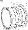
- FIG. 2 shows a perspective internal view of an example measuring section 210.
- the measuring section 210 which forms the main channel of the electromagnetic flowmeter 100 through which the conducting fluid flows through.
- the measuring section 210 includes an insulating liner 250 within the inner diameter of the measuring section in order to insulate the fluid from the rest of the measuring section 210.
- a plurality of pairs of electromagnetic coils (shown as coils 220, 222, 225, 227) are installed for generating a plurality of magnetic fields within the inner diameter of the measuring section 210.
- the plurality of pairs of coils (220, 222, 225, 227) are installed along a first plane 290 of the measuring section 210.
- the first plane 290 is perpendicular to the flow of the fluid in the measuring section 210.
- the interaction of the magnetic fields and the conducting fluid flowing through the measuring section 210 generates a voltage which is then measured by one or more measuring electrodes.
- the generated voltage is proportional to the magnetic field and the velocity of the fluid and accordingly, based on the generated voltage, the velocity of the fluid can be determined.
- each coil from each pair of coils is small and accordingly each coil does not produce a magnetic field which covers the entire cross section of the measuring section 210.
- this issue is addressed by having a plurality of pairs of coils which generate a plurality of magnetic fields. Accordingly, the plurality of magnetic fields cover the majority of the cross section of the measuring section 210. Therefore, through the usage of the small coils (where each magnetic field generated by a corresponding pair of coils covers only a part of measuring section), the ease of construction of the electromagnetic flowmeter 100 is improved and the overall cost of the electromagnetic flowmeter 100.
- the electromagnetic coils and the magnetic fields are further explained in relation to in figure 3 .
- Figure 3 shows front cross-sectional view of the example measuring section 310 illustrating the plurality of pairs of coils (shown as coils 325 and 327, 315 and 317, 335 and 337, 345 and 347).
- the plurality of pairs of coils (325 & 327, 315 & 317, 335 & 337, 345 & 347) are mounted on the measuring section 310. While in the figure, four pairs of coils (325 & 327, 315 & 317, 335 & 337, 345 & 347) are shown, there may be other combinations involving at least two pairs of coils (such as six pairs of coils, eight pairs of coils, etc.).
- Each pair of coils generates a corresponding magnetic field upon being excited by a driving current from a transmitter.
- the pair of coils 325 and 327 when excited, generate the magnetic field 330.
- the pair of coils 315 and 317 when excited, generate the magnetic field 320.
- the pairs of coils 335 and 337 when excited, generate the magnetic field 340.
- the pairs of coils 345 and 347 when excited, generate the magnetic field 350. While all the pairs of coils can be excited to generate the corresponding magnetic fields, in an example, a selected number of pairs of coils are excited for generating the corresponding magnetic fields during normal operating condition.
- first pair of coils the pairs 315 and 317 (also referred to as first pair of coils), and 335 and 337 (also referred to as second pair of coils) are excited by the transmitter for generating the magnetic fields 320 (also referred to as first magnetic field) and 340 (also referred to as second magnetic field).
- a first coil from the first pair of coils acts as one pole of the first magnetic field and a second coil from the first pair of coils acts as the second pole of the first magnetic field.
- a first coil from the second pair of coils acts as one pole of the second magnetic field and a second coil from the second pair of coils acts as the second pole of the second magnetic field.
- the first and the second magnetic fields 320 and 340 interact with the conducting fluid flowing through the measuring section 310 and generate a voltage across two or more measuring electrodes (not shown in the figure) mounted on the measuring section 310.
- the first and second pairs of coils (315 and 317, 335 and 337) are connected to and excited by the transmitter.
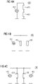
- Figure 4 illustrates a plurality of options in which the first and second pair of coils are connected.
- the first and the second pairs of coils (420, 430) are connected in series to each other and to a current source 410 associated with the transmitter. Accordingly, the same driving current is provided to the first and second pairs of coils.
- the first and second pairs of coils (420, 430) are connected in parallel to each other, as shown in section B of the figure 4 , while being connected to the same current source 410 associated with the transmitter. Accordingly, the driving current is divided between the first pair of coils 420 and the second pair of coils 430.
- the first and the second pair of coils may be connected to two different current sources (410, 415) associated with the transmitter as shown in section c of the figure 4 .
- the first pair of coils 420 are connected to the current source 410 and the second pair of the coils 430 are connected to the current source 415.
- the driving current used to excite the first pair of coils 410 may be different from the driving current used to excite the second pairs of coils 430.
- the frequency or magnitude of the driving current for exciting the first pair of coils 410 may be different from the frequency or magnitude of the driving current for exciting the second pairs of coils 430.
- the first magnetic field may be different from the second magnetic field.
- the coils 345 and 347 and coils 325 and 327 may be excited to generate a third and fourth magnetic fields (350 and 330).
- the driving current provided to the coils 345 and 347, and coils 325 and 327 may be similar or different from the currents provided to the first and second pair of coils (315 & 317, 335 & 337).
- the additional pairs of coils are excited to interact with the first and the second magnetic fields.
- the coils 325 and 327 generate the magnetic field 330 which is capable of interacting with the magnetic field 320 (generated by the coils 315 and 317) .
- the magnetic field 330 can tune the magnetic field 320 or amplify the magnetic field 320.
- the coils 345 and 347 generate the magnetic field 350 which is capable of interacting with the magnetic field 340 (generated by the coils 335 and 337).
- the magnetic field 350 can tune the magnetic field 340 or amplify the magnetic field 340.
- the current invention discloses a method 500 for measuring a volumetric flow fluid carrying channel for measuring a volumetric flow of a fluid flowing within the fluid carrying channel using an electromagnetic flowmeter as described above. This is explained using the example method 500 as shown in figure 5 .
- the method 500 is performed by the electromagnetic flowmeter.
- the transmitter of the electromagnetic flowmeter provides a first driving current to a first pair of coils for generating a first magnetic field.
- the transmitter of the electromagnetic flowmeter provides a second driving current to a second pair of coils for generating a second magnetic field.
- the transmitter measures a voltage generated across one or more measuring electrodes due to the interaction of the generated magnetic fields and the conducting fluid.
- the electromagnetic flowmeter determines the volumetric flow of the fluid.
- a magnetic circuit associated with the first magnetic field is distinct is from a magnetic circuit associated with the second magnetic field.
Landscapes
- Physics & Mathematics (AREA)
- Electromagnetism (AREA)
- Fluid Mechanics (AREA)
- General Physics & Mathematics (AREA)
- Engineering & Computer Science (AREA)
- Power Engineering (AREA)
- Measuring Volume Flow (AREA)
Priority Applications (5)
| Application Number | Priority Date | Filing Date | Title |
|---|---|---|---|
| EP21166163.2A EP4067832A1 (fr) | 2021-03-31 | 2021-03-31 | Débitmètre électromagnétique comportant une pluralité de bobines |
| US18/284,562 US12540840B2 (en) | 2021-03-31 | 2022-03-25 | Electromagnetic flowmeter with a plurality of coils |
| CN202280025902.3A CN117098973A (zh) | 2021-03-31 | 2022-03-25 | 具有多个线圈的电磁流量计 |
| PCT/EP2022/057911 WO2022207487A1 (fr) | 2021-03-31 | 2022-03-25 | Débitmètre électromagnétique pourvu d'une pluralité de bobines |
| EP22717815.9A EP4271968B1 (fr) | 2021-03-31 | 2022-03-25 | Débitmètre électromagnétique comportant une pluralité de bobines |
Applications Claiming Priority (1)
| Application Number | Priority Date | Filing Date | Title |
|---|---|---|---|
| EP21166163.2A EP4067832A1 (fr) | 2021-03-31 | 2021-03-31 | Débitmètre électromagnétique comportant une pluralité de bobines |
Publications (1)
| Publication Number | Publication Date |
|---|---|
| EP4067832A1 true EP4067832A1 (fr) | 2022-10-05 |
Family
ID=75339458
Family Applications (2)
| Application Number | Title | Priority Date | Filing Date |
|---|---|---|---|
| EP21166163.2A Withdrawn EP4067832A1 (fr) | 2021-03-31 | 2021-03-31 | Débitmètre électromagnétique comportant une pluralité de bobines |
| EP22717815.9A Active EP4271968B1 (fr) | 2021-03-31 | 2022-03-25 | Débitmètre électromagnétique comportant une pluralité de bobines |
Family Applications After (1)
| Application Number | Title | Priority Date | Filing Date |
|---|---|---|---|
| EP22717815.9A Active EP4271968B1 (fr) | 2021-03-31 | 2022-03-25 | Débitmètre électromagnétique comportant une pluralité de bobines |
Country Status (4)
| Country | Link |
|---|---|
| US (1) | US12540840B2 (fr) |
| EP (2) | EP4067832A1 (fr) |
| CN (1) | CN117098973A (fr) |
| WO (1) | WO2022207487A1 (fr) |
Cited By (1)
| Publication number | Priority date | Publication date | Assignee | Title |
|---|---|---|---|---|
| US12072219B2 (en) * | 2019-10-15 | 2024-08-27 | Enercorp Engineered Solutions, Llc | Apparatus for monitoring fluid flow in a pipe using electromagnetic velocity tomography |
Families Citing this family (1)
| Publication number | Priority date | Publication date | Assignee | Title |
|---|---|---|---|---|
| EP4075103A1 (fr) * | 2021-04-15 | 2022-10-19 | Siemens Aktiengesellschaft | Débitmètre électromagnétique doté de paires de bobines primaire et secondaire |
Citations (4)
| Publication number | Priority date | Publication date | Assignee | Title |
|---|---|---|---|---|
| WO1993015379A1 (fr) * | 1992-01-24 | 1993-08-05 | Marsh-Mcbirney, Inc. | Debitmetre a champ electromagnetique concentrique |
| WO1998052001A1 (fr) * | 1997-05-13 | 1998-11-19 | Hersey Measurement Company | Debitmetre electromagnetique |
| WO2014028450A1 (fr) * | 2012-08-14 | 2014-02-20 | Cidra Corporate Services Inc. | Tomographie à impédance magnétique-électrique modulée à profilage de flux |
| EP3184969A1 (fr) * | 2015-12-21 | 2017-06-28 | Proces-Data A/S | Débitmètre électromagnétique à électrodes multiples |
Family Cites Families (15)
| Publication number | Priority date | Publication date | Assignee | Title |
|---|---|---|---|---|
| US3490282A (en) * | 1966-07-28 | 1970-01-20 | Tokyo Shibaura Electric Co | Induction liquid flowmeters |
| DE1911556A1 (de) * | 1969-03-07 | 1970-09-24 | Krohne Fa Ludwig | Induktiver Stroemungsmesser |
| JPS62188910A (ja) * | 1986-02-14 | 1987-08-18 | Aichi Tokei Denki Co Ltd | 電磁流量計 |
| JP3263296B2 (ja) * | 1995-10-26 | 2002-03-04 | 株式会社東芝 | 電磁流量計 |
| DE502005009845D1 (de) * | 2005-09-21 | 2010-08-12 | Siemens Ag | Verfahren zum betreiben eines elektromagnetischen durchflussmessers sowie elektromagnetischer durchflussmesser |
| US8434371B2 (en) * | 2010-10-14 | 2013-05-07 | Brickhouse Innovations, Llc | Electromagnetic fluid velocity sensor with adjustable electrodes |
| US10031009B2 (en) * | 2011-08-23 | 2018-07-24 | Cidra Corporate Services, Inc. | Flow profiling techniques based on modulated magnetic-electrical impedance tomography |
| US9021890B2 (en) * | 2012-09-26 | 2015-05-05 | Rosemount Inc. | Magnetic flowmeter with multiple coils |
| DE102014004122B3 (de) * | 2014-03-24 | 2015-08-06 | Krohne Messtechnik Gmbh | Magnetisch-Induktives Durchflussmessgerät und Verfahren zum Betreiben eines magnetisch-induktiven Durchflussmessgeräts |
| CN104061969B (zh) * | 2014-07-08 | 2017-04-05 | 电子科技大学 | 一种电容式电磁流量信号转换器 |
| DE102016124976A1 (de) * | 2016-12-20 | 2018-06-21 | Endress+Hauser Flowtec Ag | Verfahren zum Betreiben eines magnetisch-induktiven Durchflussmessgeräts und ein solches Durchflussmessgerät |
| DE102017105547A1 (de) * | 2017-03-15 | 2018-09-20 | Krohne Ag | Verfahren zur Bestimmung des Strömungsprofils, Messwertumformer, magnetisch-induktives Durchflussmessgerät und Verwendung eines magnetisch-induktiven Durchflussmessgeräts |
| US11204267B2 (en) * | 2019-09-05 | 2021-12-21 | Micro Motion, Inc. | Continuously adaptive digital coil driver for magnetic flowmeter |
| CN112146715B (zh) * | 2020-08-26 | 2022-09-06 | 沈阳兰申电器有限公司 | 一种具有符合权重分布磁场的电磁流量计的励磁方法 |
| EP4075103A1 (fr) * | 2021-04-15 | 2022-10-19 | Siemens Aktiengesellschaft | Débitmètre électromagnétique doté de paires de bobines primaire et secondaire |
-
2021
- 2021-03-31 EP EP21166163.2A patent/EP4067832A1/fr not_active Withdrawn
-
2022
- 2022-03-25 US US18/284,562 patent/US12540840B2/en active Active
- 2022-03-25 CN CN202280025902.3A patent/CN117098973A/zh active Pending
- 2022-03-25 WO PCT/EP2022/057911 patent/WO2022207487A1/fr not_active Ceased
- 2022-03-25 EP EP22717815.9A patent/EP4271968B1/fr active Active
Patent Citations (4)
| Publication number | Priority date | Publication date | Assignee | Title |
|---|---|---|---|---|
| WO1993015379A1 (fr) * | 1992-01-24 | 1993-08-05 | Marsh-Mcbirney, Inc. | Debitmetre a champ electromagnetique concentrique |
| WO1998052001A1 (fr) * | 1997-05-13 | 1998-11-19 | Hersey Measurement Company | Debitmetre electromagnetique |
| WO2014028450A1 (fr) * | 2012-08-14 | 2014-02-20 | Cidra Corporate Services Inc. | Tomographie à impédance magnétique-électrique modulée à profilage de flux |
| EP3184969A1 (fr) * | 2015-12-21 | 2017-06-28 | Proces-Data A/S | Débitmètre électromagnétique à électrodes multiples |
Cited By (1)
| Publication number | Priority date | Publication date | Assignee | Title |
|---|---|---|---|---|
| US12072219B2 (en) * | 2019-10-15 | 2024-08-27 | Enercorp Engineered Solutions, Llc | Apparatus for monitoring fluid flow in a pipe using electromagnetic velocity tomography |
Also Published As
| Publication number | Publication date |
|---|---|
| US20240175732A1 (en) | 2024-05-30 |
| CN117098973A (zh) | 2023-11-21 |
| WO2022207487A1 (fr) | 2022-10-06 |
| US12540840B2 (en) | 2026-02-03 |
| EP4271968B1 (fr) | 2025-06-11 |
| EP4271968A1 (fr) | 2023-11-08 |
Similar Documents
| Publication | Publication Date | Title |
|---|---|---|
| RU2615205C2 (ru) | Магнитный расходомер с множественными катушками | |
| JP3263296B2 (ja) | 電磁流量計 | |
| JP6114267B2 (ja) | 可変周波数型電磁流量計 | |
| EP4271968B1 (fr) | Débitmètre électromagnétique comportant une pluralité de bobines | |
| JP5818415B2 (ja) | 電磁流量計測システムの校正装置 | |
| JP6272500B2 (ja) | 磁気流量計のための改善された磁性コア構成 | |
| CN110178001B (zh) | 用于操作磁感应流量计的方法和这种磁感应流量计 | |
| EP3022532B1 (fr) | Débitmètre magnétique | |
| US20230213367A1 (en) | Method of operating a magnetically-inductive flowmeter | |
| WO2012132363A1 (fr) | Débitmètre électromagnétique, système électromagnétique de mesure de débit et procédé associé | |
| CN118369555A (zh) | 磁感应流量测量设备 | |
| US20170248452A1 (en) | Magnetic-inductive flowmeter and corresponding method | |
| JP6183309B2 (ja) | 流量計及び絶縁劣化診断システム | |
| EP4275018B1 (fr) | Débitmètre électromagnétique doté de paires de bobines primaire et secondaire | |
| US7267012B2 (en) | Electromagnetic flowmeter including electrodes and magnetic pole placed in proximity on one side of the outer wall | |
| CN114341596A (zh) | 磁感应流量计 | |
| US9791305B2 (en) | Apparatus for measuring a liquid flow | |
| RU2239789C1 (ru) | Способ измерения расхода жидкости и электромагнитный преобразователь для измерения расхода жидкости | |
| RU2310816C2 (ru) | Вихревой электромагнитный преобразователь расхода жидкого металла | |
| CN119618324A (zh) | 高动态宽频谱交变驱动的多通道融合感知电磁测量方法 |
Legal Events
| Date | Code | Title | Description |
|---|---|---|---|
| PUAI | Public reference made under article 153(3) epc to a published international application that has entered the european phase |
Free format text: ORIGINAL CODE: 0009012 |
|
| STAA | Information on the status of an ep patent application or granted ep patent |
Free format text: STATUS: THE APPLICATION HAS BEEN PUBLISHED |
|
| AK | Designated contracting states |
Kind code of ref document: A1 Designated state(s): AL AT BE BG CH CY CZ DE DK EE ES FI FR GB GR HR HU IE IS IT LI LT LU LV MC MK MT NL NO PL PT RO RS SE SI SK SM TR |
|
| STAA | Information on the status of an ep patent application or granted ep patent |
Free format text: STATUS: THE APPLICATION IS DEEMED TO BE WITHDRAWN |
|
| 18D | Application deemed to be withdrawn |
Effective date: 20230406 |