EP3376331B1 - Procédé de fonctionnement d'un appareil de traitement de sol mobile automatique - Google Patents
Procédé de fonctionnement d'un appareil de traitement de sol mobile automatique Download PDFInfo
- Publication number
- EP3376331B1 EP3376331B1 EP18159437.5A EP18159437A EP3376331B1 EP 3376331 B1 EP3376331 B1 EP 3376331B1 EP 18159437 A EP18159437 A EP 18159437A EP 3376331 B1 EP3376331 B1 EP 3376331B1
- Authority
- EP
- European Patent Office
- Prior art keywords
- treatment apparatus
- floor treatment
- soil cultivation
- information signal
- signal output
- Prior art date
- Legal status (The legal status is an assumption and is not a legal conclusion. Google has not performed a legal analysis and makes no representation as to the accuracy of the status listed.)
- Active
Links
Images


Classifications
-
- A—HUMAN NECESSITIES
- A47—FURNITURE; DOMESTIC ARTICLES OR APPLIANCES; COFFEE MILLS; SPICE MILLS; SUCTION CLEANERS IN GENERAL
- A47L—DOMESTIC WASHING OR CLEANING; SUCTION CLEANERS IN GENERAL
- A47L11/00—Machines for cleaning floors, carpets, furniture, walls, or wall coverings
- A47L11/24—Floor-sweeping machines, motor-driven
-
- A—HUMAN NECESSITIES
- A47—FURNITURE; DOMESTIC ARTICLES OR APPLIANCES; COFFEE MILLS; SPICE MILLS; SUCTION CLEANERS IN GENERAL
- A47L—DOMESTIC WASHING OR CLEANING; SUCTION CLEANERS IN GENERAL
- A47L9/00—Details or accessories of suction cleaners, e.g. mechanical means for controlling the suction or for effecting pulsating action; Storing devices specially adapted to suction cleaners or parts thereof; Carrying-vehicles specially adapted for suction cleaners
- A47L9/28—Installation of the electric equipment, e.g. adaptation or attachment to the suction cleaner; Controlling suction cleaners by electric means
- A47L9/30—Arrangement of illuminating devices
-
- A—HUMAN NECESSITIES
- A47—FURNITURE; DOMESTIC ARTICLES OR APPLIANCES; COFFEE MILLS; SPICE MILLS; SUCTION CLEANERS IN GENERAL
- A47L—DOMESTIC WASHING OR CLEANING; SUCTION CLEANERS IN GENERAL
- A47L11/00—Machines for cleaning floors, carpets, furniture, walls, or wall coverings
- A47L11/29—Floor-scrubbing machines characterised by means for taking-up dirty liquid
- A47L11/30—Floor-scrubbing machines characterised by means for taking-up dirty liquid by suction
-
- A—HUMAN NECESSITIES
- A47—FURNITURE; DOMESTIC ARTICLES OR APPLIANCES; COFFEE MILLS; SPICE MILLS; SUCTION CLEANERS IN GENERAL
- A47L—DOMESTIC WASHING OR CLEANING; SUCTION CLEANERS IN GENERAL
- A47L11/00—Machines for cleaning floors, carpets, furniture, walls, or wall coverings
- A47L11/40—Parts or details of machines not provided for in groups A47L11/02 - A47L11/38, or not restricted to one of these groups, e.g. handles, arrangements of switches, skirts, buffers, levers
- A47L11/4002—Installations of electric equipment
- A47L11/4008—Arrangements of switches, indicators or the like
-
- A—HUMAN NECESSITIES
- A47—FURNITURE; DOMESTIC ARTICLES OR APPLIANCES; COFFEE MILLS; SPICE MILLS; SUCTION CLEANERS IN GENERAL
- A47L—DOMESTIC WASHING OR CLEANING; SUCTION CLEANERS IN GENERAL
- A47L11/00—Machines for cleaning floors, carpets, furniture, walls, or wall coverings
- A47L11/40—Parts or details of machines not provided for in groups A47L11/02 - A47L11/38, or not restricted to one of these groups, e.g. handles, arrangements of switches, skirts, buffers, levers
- A47L11/4011—Regulation of the cleaning machine by electric means; Control systems and remote control systems therefor
-
- A—HUMAN NECESSITIES
- A47—FURNITURE; DOMESTIC ARTICLES OR APPLIANCES; COFFEE MILLS; SPICE MILLS; SUCTION CLEANERS IN GENERAL
- A47L—DOMESTIC WASHING OR CLEANING; SUCTION CLEANERS IN GENERAL
- A47L11/00—Machines for cleaning floors, carpets, furniture, walls, or wall coverings
- A47L11/40—Parts or details of machines not provided for in groups A47L11/02 - A47L11/38, or not restricted to one of these groups, e.g. handles, arrangements of switches, skirts, buffers, levers
- A47L11/4061—Steering means; Means for avoiding obstacles; Details related to the place where the driver is accommodated
-
- A—HUMAN NECESSITIES
- A47—FURNITURE; DOMESTIC ARTICLES OR APPLIANCES; COFFEE MILLS; SPICE MILLS; SUCTION CLEANERS IN GENERAL
- A47L—DOMESTIC WASHING OR CLEANING; SUCTION CLEANERS IN GENERAL
- A47L9/00—Details or accessories of suction cleaners, e.g. mechanical means for controlling the suction or for effecting pulsating action; Storing devices specially adapted to suction cleaners or parts thereof; Carrying-vehicles specially adapted for suction cleaners
- A47L9/28—Installation of the electric equipment, e.g. adaptation or attachment to the suction cleaner; Controlling suction cleaners by electric means
- A47L9/2857—User input or output elements for control, e.g. buttons, switches or displays
-
- A—HUMAN NECESSITIES
- A47—FURNITURE; DOMESTIC ARTICLES OR APPLIANCES; COFFEE MILLS; SPICE MILLS; SUCTION CLEANERS IN GENERAL
- A47L—DOMESTIC WASHING OR CLEANING; SUCTION CLEANERS IN GENERAL
- A47L9/00—Details or accessories of suction cleaners, e.g. mechanical means for controlling the suction or for effecting pulsating action; Storing devices specially adapted to suction cleaners or parts thereof; Carrying-vehicles specially adapted for suction cleaners
- A47L9/28—Installation of the electric equipment, e.g. adaptation or attachment to the suction cleaner; Controlling suction cleaners by electric means
- A47L9/2868—Arrangements for power supply of vacuum cleaners or the accessories thereof
- A47L9/2884—Details of arrangements of batteries or their installation
-
- A—HUMAN NECESSITIES
- A47—FURNITURE; DOMESTIC ARTICLES OR APPLIANCES; COFFEE MILLS; SPICE MILLS; SUCTION CLEANERS IN GENERAL
- A47L—DOMESTIC WASHING OR CLEANING; SUCTION CLEANERS IN GENERAL
- A47L9/00—Details or accessories of suction cleaners, e.g. mechanical means for controlling the suction or for effecting pulsating action; Storing devices specially adapted to suction cleaners or parts thereof; Carrying-vehicles specially adapted for suction cleaners
- A47L9/28—Installation of the electric equipment, e.g. adaptation or attachment to the suction cleaner; Controlling suction cleaners by electric means
- A47L9/2894—Details related to signal transmission in suction cleaners
-
- B—PERFORMING OPERATIONS; TRANSPORTING
- B60—VEHICLES IN GENERAL
- B60Q—ARRANGEMENT OF SIGNALLING OR LIGHTING DEVICES, THE MOUNTING OR SUPPORTING THEREOF OR CIRCUITS THEREFOR, FOR VEHICLES IN GENERAL
- B60Q1/00—Arrangement of optical signalling or lighting devices, the mounting or supporting thereof or circuits therefor
- B60Q1/26—Arrangement of optical signalling or lighting devices, the mounting or supporting thereof or circuits therefor the devices being primarily intended to indicate the vehicle, or parts thereof, or to give signals, to other traffic
- B60Q1/50—Arrangement of optical signalling or lighting devices, the mounting or supporting thereof or circuits therefor the devices being primarily intended to indicate the vehicle, or parts thereof, or to give signals, to other traffic for indicating other intentions or conditions, e.g. request for waiting or overtaking
-
- G—PHYSICS
- G05—CONTROLLING; REGULATING
- G05D—SYSTEMS FOR CONTROLLING OR REGULATING NON-ELECTRIC VARIABLES
- G05D1/00—Control of position, course, altitude or attitude of land, water, air or space vehicles, e.g. using automatic pilots
- G05D1/0055—Control of position, course, altitude or attitude of land, water, air or space vehicles, e.g. using automatic pilots with safety arrangements
-
- G—PHYSICS
- G05—CONTROLLING; REGULATING
- G05D—SYSTEMS FOR CONTROLLING OR REGULATING NON-ELECTRIC VARIABLES
- G05D1/00—Control of position, course, altitude or attitude of land, water, air or space vehicles, e.g. using automatic pilots
- G05D1/02—Control of position or course in two dimensions
- G05D1/021—Control of position or course in two dimensions specially adapted to land vehicles
- G05D1/0268—Control of position or course in two dimensions specially adapted to land vehicles using internal positioning means
- G05D1/0274—Control of position or course in two dimensions specially adapted to land vehicles using internal positioning means using mapping information stored in a memory device
-
- G—PHYSICS
- G07—CHECKING-DEVICES
- G07C—TIME OR ATTENDANCE REGISTERS; REGISTERING OR INDICATING THE WORKING OF MACHINES; GENERATING RANDOM NUMBERS; VOTING OR LOTTERY APPARATUS; ARRANGEMENTS, SYSTEMS OR APPARATUS FOR CHECKING NOT PROVIDED FOR ELSEWHERE
- G07C5/00—Registering or indicating the working of vehicles
- G07C5/08—Registering or indicating performance data other than driving, working, idle, or waiting time, with or without registering driving, working, idle or waiting time
- G07C5/0808—Diagnosing performance data
-
- G—PHYSICS
- G07—CHECKING-DEVICES
- G07C—TIME OR ATTENDANCE REGISTERS; REGISTERING OR INDICATING THE WORKING OF MACHINES; GENERATING RANDOM NUMBERS; VOTING OR LOTTERY APPARATUS; ARRANGEMENTS, SYSTEMS OR APPARATUS FOR CHECKING NOT PROVIDED FOR ELSEWHERE
- G07C5/00—Registering or indicating the working of vehicles
- G07C5/08—Registering or indicating performance data other than driving, working, idle, or waiting time, with or without registering driving, working, idle or waiting time
- G07C5/0816—Indicating performance data, e.g. occurrence of a malfunction
- G07C5/0825—Indicating performance data, e.g. occurrence of a malfunction using optical means
-
- A—HUMAN NECESSITIES
- A47—FURNITURE; DOMESTIC ARTICLES OR APPLIANCES; COFFEE MILLS; SPICE MILLS; SUCTION CLEANERS IN GENERAL
- A47L—DOMESTIC WASHING OR CLEANING; SUCTION CLEANERS IN GENERAL
- A47L2201/00—Robotic cleaning machines, i.e. with automatic control of the travelling movement or the cleaning operation
- A47L2201/04—Automatic control of the travelling movement; Automatic obstacle detection
-
- A—HUMAN NECESSITIES
- A47—FURNITURE; DOMESTIC ARTICLES OR APPLIANCES; COFFEE MILLS; SPICE MILLS; SUCTION CLEANERS IN GENERAL
- A47L—DOMESTIC WASHING OR CLEANING; SUCTION CLEANERS IN GENERAL
- A47L2201/00—Robotic cleaning machines, i.e. with automatic control of the travelling movement or the cleaning operation
- A47L2201/06—Control of the cleaning action for autonomous devices; Automatic detection of the surface condition before, during or after cleaning
-
- B—PERFORMING OPERATIONS; TRANSPORTING
- B60—VEHICLES IN GENERAL
- B60Q—ARRANGEMENT OF SIGNALLING OR LIGHTING DEVICES, THE MOUNTING OR SUPPORTING THEREOF OR CIRCUITS THEREFOR, FOR VEHICLES IN GENERAL
- B60Q2400/00—Special features or arrangements of exterior signal lamps for vehicles
- B60Q2400/50—Projected symbol or information, e.g. onto the road or car body
-
- B—PERFORMING OPERATIONS; TRANSPORTING
- B60—VEHICLES IN GENERAL
- B60Q—ARRANGEMENT OF SIGNALLING OR LIGHTING DEVICES, THE MOUNTING OR SUPPORTING THEREOF OR CIRCUITS THEREFOR, FOR VEHICLES IN GENERAL
- B60Q2800/00—Features related to particular types of vehicles not otherwise provided for
- B60Q2800/20—Utility vehicles, e.g. for agriculture, construction work
Definitions
- the invention relates to a method for operating a soil cultivation device that moves automatically within an environment, a control and evaluation device of the soil cultivation device monitoring the operating status of the soil cultivation device, recognizing an error condition of the soil cultivation device and, if an error condition occurs, an information signal is output.
- the invention relates to a soil cultivation device that moves automatically within an environment with a control and evaluation device which is set up to monitor an operating status of the soil cultivation device, to detect an error state of the soil cultivation device and, if an error state occurs, to cause an information signal to be output .
- the EP 1 936 463 A2 known as vacuum robots and / or mopping robots trained floor preparation devices, which can move automatically within an environment.
- they have a navigation and self-localization device, by means of which a map of the surroundings of the soil cultivation device can be created and an own position of the soil cultivation device can be recognized.
- the navigation and Self-locating device reads out measurement data that the tillage device has detected within the environment.
- the soil cultivation device can have a distance sensor and an odometry sensor which detect distances from obstacles or distances covered.
- the soil cultivation device can orient itself within the environment based on the created environment map and the currently recorded measurement data.
- an information signal is output to a user of the soil cultivation device, which informs the user about the error status.
- the information signal is usually a sequence of tones that draws the user's attention to the soil cultivation implement.
- tone sequences can have a disruptive effect on the user and / or other people in the vicinity of the soil cultivation device, especially if they are output regularly. Finding the soil cultivation device is also difficult if the tone sequences are emitted in regular, but relatively far apart, time segments. Last but not least, it is difficult for people who are hard of hearing or even deaf to take notice of the information signal.
- a method according to claim 1 for operating an automatically moving soil cultivation device in which an optical signal output device of the soil cultivation device emits the optical information signal, the optical information signal generating a light projection representing a direction, the light projection on a projection location within the environment of the current location of the soil cultivation device is directed, and the directional information from the projection location within the environment in the direction of the current location of the soil cultivation device.
- an error state of the soil cultivation device is no longer indicated by means of an acoustic signal, for example a tone sequence, but rather by an optical information signal which is projected by the signal output device to a projection location within the environment of the soil cultivation device.
- an acoustic signal for example a tone sequence
- an optical information signal which is projected by the signal output device to a projection location within the environment of the soil cultivation device.
- the direction information include the representation of an arrow which, starting from the projection location, points to the soil cultivation device. The user therefore only has to look in the direction indicated by the arrow and can thus find the soil cultivation device, for example, under a bed, a cupboard or the like.
- the projection location at which the information signal is projected can be, for example, a sub-area of a floor surface, a front of a piece of furniture, a sub-area of a wall or the like.
- the information signal is emitted when the control and evaluation device detects jamming, hindrance and / or blocking of the soil cultivation device, a charge status of a battery below a defined minimum charge status and / or a faulty software status.
- error states hinder or prevent further travel of the soil cultivation device within the environment or at least an optimal cultivation success of the soil cultivation device.
- the error states include, on the one hand, states in which the soil cultivation device has got stuck under a piece of furniture, such as a bed, a sofa, a chest of drawers or the like, and can no longer be released there under its own power.
- an error state can relate to a situation in which a drive device and / or a driven wheel of the soil cultivation device is blocked and thus prevents or at least impairs movement. Furthermore, the soil cultivation device can also be blocked by obstacles which do not jam the soil cultivation device, but hinder it in its further travel, namely in such a way that the soil cultivation device cannot navigate itself out of this situation. In these error states, it may be necessary for the user to remove the soil cultivation implement from the situation.
- Other error states are, for example, insufficient charge levels of a battery of the soil cultivation device, an error in the operating software of the soil cultivation device, which prevents locomotion and / or proper operation of the soil cultivation device. The above list is not to be understood as exhaustive. Rather, other error states are also conceivable which require or at least recommend intervention by the user.
- the signal output device automatically emits the information signal immediately after detecting an error state.
- an information signal is sent out by the signal output device immediately when the control and evaluation device of the soil cultivation device detects an error condition.
- the user of the soil cultivation device does not have to take any measures to request an information signal. Rather, the information signal is automatically projected into the environment of the soil cultivation device, for example on a floor or on a wall or piece of furniture, so that the user notices the information signal when present in this environment and becomes aware of a fault condition of the soil cultivation device. The user can then determine the location of the soil cultivation device on the basis of the directional information present in the information signal, find the soil cultivation device and rectify the fault condition.
- the control and evaluation device sends a message about the error state to an external device in communication with the soil cultivation device, the user manually initiating an output of an information signal by the signal output device of the soil cultivation device by means of the external device.
- the information signal is not automatically emitted as soon as an error condition occurs of the soil cultivation device is determined, but only if there is also a specific request from the user of the soil cultivation device.
- the user is informed of the error condition by means of a message. He can then decide whether or not an optical information signal should be emitted.
- the message about the error status is advantageously sent to a mobile device of the user, for example a mobile phone, a tablet computer, a laptop or the like.
- the information signal can also be sent to a local PC, a remote server or the like.
- the signal output device is therefore only operated when the user specifically requests it. This can save energy for unnecessary or undesired light projections.
- the user's external device can have an application that is in communication with the soil cultivation device and that indicates an error state to the user.
- the message not only contains information about the occurrence of an error state, but also additional information, for example information about the type of error state, a suggestion for eliminating the error state, information about when the error state began consists and the like.
- the user can use the application of the external device to send a signal to the soil cultivation device, which causes the output of an information signal so that the signal output device of the soil cultivation device only projects an information signal into the environment when the user is ready to search for the soil cultivation device and / or is in the vicinity of the soil cultivation device.
- the control and evaluation device recognize a current position and orientation of the soil cultivation device on the basis of an environment map, environment information in the area of the soil cultivation device evaluates and projects the optical information signal to a projection location in the environment, which is free of obstacles in relation to a size and direction of the light projection and / or can be seen from a bird's eye view.
- This embodiment is particularly suitable in connection with a navigation and self-localization device of the soil cultivation device, which creates a map of the surroundings of the soil cultivation device.
- the soil cultivation device has, for example, one or a plurality of sensors, for example a distance measuring device and / or an odometry measuring device.
- a map of the surroundings can be created in which the positions of the obstacles and / or room boundaries are noted.
- the control and evaluation device can access this map created by the soil cultivation device itself, or a map of the surroundings transmitted to the soil cultivation device from another device, in order to determine a suitable projection location for the projection of the optical information signal.
- the control and evaluation device selects a projection location which is free of obstacles and / or can be seen by the user of the soil cultivation device.
- the control and evaluation device select a signal output device from a plurality of signal output devices of the soil cultivation device, the selected signal output device being closest to the projection location.
- the soil cultivation device has a plurality of signal output devices which are arranged, for example, along a circumference of the soil cultivation device. From the majority of these signal output devices, the control and evaluation device selects one or more signal output devices which are closest to an optimal projection location or are best suited to project the information signal at this projection location.
- the control and evaluation device has knowledge of the positions and orientations of the signal output devices on the soil cultivation device on the one hand, and on the other hand of the current location and the current orientation of the soil cultivation device within the environment, so that, on the one hand, a suitable projection location for displaying the directional information contained information signal and on the other hand the currently most suitable for the projection, d. H. positioned, signal output device can be determined.
- the signal output device for projecting the information signal at the projection location is relocated relative to a housing of the soil cultivation device and / or that the information signal emitted by a light source of the signal output device is deflected by means of an optical deflection device.
- the signal output device can be arranged, for example, on an adjustable carrier on the housing of the soil cultivation device.
- the signal output device or a light source thereof can be permanently connected to the housing of the soil cultivation device, the signal output device or the light source, however, having an optical deflection device is combined, for example a pivotable mirror, a prism or the like.
- the deflection device directs the information signal, starting from the light source of the signal output device, to the desired projection location.
- the invention also proposes a soil cultivation device that moves automatically within an environment with a control and evaluation device according to claim 8, the control and evaluation device being set up to monitor an operating status of the soil cultivation device, to detect a fault condition of the soil cultivation device and, in the event of an error condition, to cause an output of an information signal, the soil cultivation device having an optical signal output device which is set up to emit the optical information signal, the optical information signal generating a light projection representing a directional indication, wherein the light projection is directed onto a projection location within the vicinity of the current location of the soil cultivation device, and the directional information from shows a projection location within the environment in the direction of the current location of the soil cultivation device.
- the proposed soil cultivation device is designed to carry out a previously described method in which an information signal which contains a directional indication to a soil cultivation device is projected onto a projection location.
- the soil cultivation device has an optical signal output device which usually has at least one light source, for example an LED or a laser.
- the signal output device is designed such that it projects a light beam or light cone onto the projection location in such a way that the in the Directional information contained in the optical information signal can be recognized by a user of the soil cultivation device.
- the directional information is, for example, an arrow which, starting from the projection location, points in the direction of the soil cultivation device, for example under a piece of furniture, a partial area of the surroundings that the user cannot currently see, or the like.
- the signal output device have a multiplicity of light sources and / or that the signal output device have a light source with a variable diaphragm.
- the signal output device can, for example, have an LED array, the LEDs of which can be activated to display a directional indication.
- the information signal generated by the signal output device can then be focused, collimated and / or deflected onto the desired projection location by means of optical elements, so that the information signal with the directional information contained therein can be recognized by the user of the soil cultivation device.
- the signal output device can have only a single light source, to which a variable diaphragm for displaying different information signals or directional information contained therein is assigned.
- the diaphragm generates, for example, the outline of an arrow within the information signal projected onto the projection location.
- the signal output device is displaceable relative to a housing of the soil cultivation device and / or that the signal output device has an optical deflection device that can be displaced relative to the housing for deflecting the emitted information signal to the projection location.
- the signal output device is designed in both cases, the information signal to different projection locations to project the environment in that the signal output device or the deflection device is displaced, for example pivoted relative to the housing of the soil cultivation device.
- the signal output device can be mounted on a movable carrier of the soil cultivation device, the carrier advantageously being displaceable by a motor and controllable by means of the control and evaluation device. By moving the carrier, the information signal can be projected at different projection locations.
- a light source of the signal output device can, for example, also be immovably mounted on the housing of the soil cultivation device and can be used in combination with a displaceable deflection device which projects the information signal emitted by the light source to a desired projection location.
- the displaceable deflection device can be, for example, a displaceable optical element such as a mirror, a prism or the like.
- the soil cultivation device can have a navigation and self-localization device which creates a map of the surroundings.
- the control and evaluation device can select the optimal projection location and, if necessary, also one of several possible signal output devices which is suitable for projecting the information signal onto the selected projection location.
- a set of a soil cultivation device and an external device of the user of the soil cultivation device is proposed, the soil cultivation device and the external device being in communication with one another in such a way that the control and evaluation device of the soil cultivation device sends a message about an error state to the external device, the message being displayed, for example, on a display of the external device and wherein the user can manually cause an information signal to be output by the signal output device of the soil cultivation device by means of the external device.
- the external device thus serves as a remote control device for the soil cultivation device.
- the set comprising the soil cultivation device and the external device is designed so that the user can find the soil cultivation device and rectify an error condition, even if the soil cultivation device cannot currently be seen from the user's location.
- Figure 1 shows an environment, which here represents a sub-area of an apartment.
- a soil cultivation device 1 is located within the surroundings, which is designed here, for example, as an automatically moving vacuum robot.
- the soil cultivation device 1 has two cleaning elements 13, namely a bristle roller arranged below a housing 10 of the soil cultivation device 1 and a side brush arranged in a corner area of the housing 10, by means of which, in particular, transition areas between a floor and a wall can be cleaned.
- the soil cultivation device 1 has wheels 14 which are motor-driven and thus serve to move the soil cultivation device 1 within the environment.
- the surroundings have a large number of obstacles 9, which here are, for example, room boundaries, a closet, a bed and two bedside tables.
- the obstacles 9 are at least partially designed so that the soil cultivation device 1 can get under them during a movement.
- the soil cultivation device 1 has a navigation and self-localization device (not shown) which reads out data from a distance measuring device 12 of the soil cultivation device 1, which here includes, for example, a triangulation measuring device.
- the distance measuring device 12 is used to determine distances to the obstacles 9 and to a map of the surroundings 7 (see FIG Figure 6 ) combined. In the environment map 7 are the obstacles 9 and also the current location of the soil cultivation device 1 included. While the soil cultivation device 1 is moving, the map 7 of the surroundings is continuously updated.
- the navigation and self-localization device is in communication with a control and evaluation device of the soil cultivation device 1, which monitors the operating status of the soil cultivation device 1, can detect an error state of the soil cultivation device 1 and, in the event of an error state, can cause an information signal 2 to be output a user of the soil cultivation device 1 is informed of the error status.
- FIG. 2 shows the soil cultivation device 1 in a perspective view from the outside.
- the soil cultivation device 1 has a plurality of signal output devices 3 which are arranged along the circumference of the housing 10.
- Each signal output device 3 here has a plurality of light sources 11 which are arranged next to one another and one below the other in the manner of an array.
- the light sources 11 of the respective signal output device 3 can be controlled by means of the control and evaluation device in such a way that certain light sources 11 of the respective signal output device 3 emit a light beam, so that the information signal 2 emitted as a whole by the array as a graphic representation, as in a standard LED television arises.
- the light sources 11 can additionally be assigned an optical element which focuses the optical information signal 2 and makes information contained therein readable for a user.
- the soil cultivation device 1 can also additionally have a displaceable carrier for the signal output device 3, so that the direction of emission of the information signal 2 can be varied.
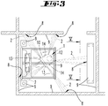
- FIG 3 shows the in Figure 1 Environment shown, in which the soil cultivation device 1 has jammed under an obstacle 9, here a bed.
- the jamming takes place, for example, due to a slatted frame hanging down under the bed, which changes a height difference between the soil cultivation device 1 and the bed.
- the control and evaluation device of the soil cultivation device 1 recognizes a fault condition of the soil cultivation device 1, namely jamming in which the soil cultivation device 1 can no longer move on its own.
- the signal output devices 3 of the soil cultivation device 1 emit information signals 2 to several projection locations 8 in the surroundings, here for example to obstacles 9, such as a closet and room boundaries (walls), or on a floor surface.
- the information signals 2 extend, starting from the soil cultivation device 1, outside the outline of the bed covering the soil cultivation device 1. A user can thereby become aware of the information signal 2.
- Figure 4 shows the soil cultivation device 1 below the obstacle 9, namely below the bed, the housing 10 being in contact with the obstacle 9 and being unable to move further under its own drive due to the frictional force that occurs.
- the soil cultivation device 1 thus has a fault condition due to being trapped underneath the obstacle 9.
- the control and evaluation device of the soil cultivation device 1 After the control and evaluation device of the soil cultivation device 1 has recognized the error state, for example because when a driving force is applied to the wheels 14, no movement of the soil cultivation device 1 can be detected by means of the distance measuring device 12, the control and evaluation device causes the signal output devices 3 to send an information signal 2 in each case to project into the environment.
- Figure 5 shows an environment as basically already in Figure 3 is shown, with an information signal 2 projected here onto the floor.
- a projection location 8 is thus created on the floor, on which the information signal 2 is displayed or becomes visible.
- the information signal 2 has a directional indication 5, namely here an arrow, which points in the direction of the current location of the soil cultivation device 1 below the bed.
- such an information signal 2 could also be projected onto an obstacle 9 in the vicinity instead of onto a floor or a floor surface.
- the arrow containing the direction indication 5 results from a projection of a multiplicity of light beams which were emitted by an array of the signal output device 3 containing a plurality of light sources 11.
- different images, in particular directional information can be displayed.
- the information signal 2 has a special color, flashes at certain intervals or the like.
- a projection device comparable to a beamer can also be provided on the floor cleaning device, with automatic focusing preferably also being implemented.
- a laser diode in the range of a visible wavelength in a plurality of lines, preferably horizontally oriented lines, which are then arranged vertically one below the other, an image could be projected correspondingly composed of image lines.
- Figure 6 shows an external device 6 which can be used in combination with the soil cultivation device 1.
- the external device 6 is here, for example, a mobile phone with a display 4 on which one of the soil cultivation device 1 created environment map 7 is displayed.
- An application is installed on the external device 6 which receives messages about error states from the soil cultivation device 1 and offers the user assistance in finding the soil cultivation device 1 and / or in eliminating the error state.
- the soil cultivation device 1 can be used in connection with the external device 6, for example, in such a way that, in the event of an error condition of the soil cultivation device 1, the user first receives a message about the occurrence of the error condition on the external device 6.
- An environment map 7 of the environment of the soil cultivation device 1 is shown on the display 4 of the external device 6, in which, among other things, the current location of the soil cultivation device 1 is shown.
- the application installed on the external device 6 provides a number of options for action that enable a reaction to the error state.
- the user can perform a remote control of the soil cultivation device 1 under the menu item "Manual control" in such a way that he navigates the soil cultivation device 1 out of the clamped position, for example by means of a joystick control.
- further driven elements can be activated to rectify the fault condition, such as rotating cleaning elements 13, in order to free the soil cultivation device 1 under the obstacle 9.
- the user can also select the "Light signal” menu item. This causes an information signal 2 to be output by one or more signal output devices 3 of the soil cultivation device 1.
- the information signal 2 or the directional information 5 contained therein show the user the location of the soil cultivation device 1, so that the user can free the soil cultivation device 1 from the situation. After the user has freed the soil cultivation device 1, the user can on the external device 6 press the "delete errors” button so that a new operation of the soil cultivation device 1 can be started.
- the user To find the soil cultivation device 1 at a location not visible to the user below the obstacle 9, the user follows the directional information 5 contained in the information signal 2, which, starting from the projection location 8, points under the obstacle 9 (bed) jamming the soil cultivation device 1.
Landscapes
- Engineering & Computer Science (AREA)
- Mechanical Engineering (AREA)
- Physics & Mathematics (AREA)
- General Physics & Mathematics (AREA)
- Radar, Positioning & Navigation (AREA)
- Aviation & Aerospace Engineering (AREA)
- Remote Sensing (AREA)
- Automation & Control Theory (AREA)
- Control Of Position, Course, Altitude, Or Attitude Of Moving Bodies (AREA)
- Electric Vacuum Cleaner (AREA)
- Lifting Devices For Agricultural Implements (AREA)
- Guiding Agricultural Machines (AREA)
- Agricultural Machines (AREA)
- Cultivation Receptacles Or Flower-Pots, Or Pots For Seedlings (AREA)
- Optical Communication System (AREA)
- Processing Of Solid Wastes (AREA)
Claims (10)
- Procédé de fonctionnement d'un dispositif de traitement du sol (1) qui se déplace automatiquement dans un environnement, dans lequel un dispositif de commande et d'évaluation du dispositif de traitement du sol (1) surveille l'état de fonctionnement du dispositif de traitement du sol (1), détecte un état de défaut du dispositif de traitement du sol (1) et, en cas d'apparition d'un état de défaut, provoque la sortie d'un signal d'information optique (2), caractérisé en ce qu'un dispositif de sortie de signal optique (3) du dispositif de traitement du sol (1) émet le signal d'information optique (2), dans lequel le signal d'information optique (2) génère une projection de lumière représentant une indication directionnelle (5), dans lequel la projection de lumière est dirigée vers un emplacement de projection (8) dans l'environnement de l'emplacement actuel du dispositif de traitement du sol (1), et dans lequel l'indication directionnelle (5) pointe de l'emplacement de projection (8) dans l'environnement en direction de l'emplacement actuel du dispositif de traitement du sol (1).
- Procédé selon la revendication 1, caractérisé en ce que le signal d'information optique (2) est émis lorsque l'appareil de commande et d'évaluation détecte un coincement, une obstruction et/ou un blocage du dispositif de traitement du sol (1), un état de charge d'un accumulateur ou batterie inférieur à un état de charge minimal défini et/ou un état logiciel défectueux.
- Procédé selon la revendication 1 ou 2, caractérisé en ce que le dispositif de sortie de signal (3) émet automatiquement le signal d'information optique (2) immédiatement après avoir détecté un état de défaut.
- Procédé selon la revendication 1 ou 2, caractérisé en ce que, en cas d'état de défaut, le dispositif de commande et d'évaluation envoie un message concernant l'état de défaut à un dispositif externe (6) qui est en liaison de communication avec le dispositif de traitement du sol (1), dans lequel l'utilisateur déclenche manuellement, au moyen du dispositif externe (6), une sortie d'un signal d'information (2) par le dispositif de sortie de signal (3) du dispositif de traitement du sol (1).
- Procédé selon l'une des revendications précédentes, caractérisé en ce que le dispositif de commande et d'évaluation détermine une position et une orientation actuelles du dispositif de traitement du sol (1) à l'aide d'une carte de l'environnement (7), évalue des informations concernant l'environnement dans la zone du dispositif de traitement du sol (1) et projette le signal d'information optique (2) sur un emplacement de projection (8) de l'environnement qui, par rapport à une taille et à une direction de la projection lumineuse, est libre d'obstacles (9) et/ou est visible en vue d'oiseau.
- Procédé selon la revendication 5, caractérisé en ce que le dispositif de commande et d'évaluation sélectionne un dispositif de sortie de signal (3) parmi une pluralité de dispositifs de sortie de signal (3) du dispositif de traitement du sol (1), dans lequel le dispositif de sortie de signal (3) sélectionné est le plus proche de l'emplacement de projection (8).
- Procédé selon l'une des revendications précédentes, caractérisé en ce que le dispositif de sortie de signal (3) pour la projection du signal d'information optique (2) sur l'emplacement de projection (8) est déplacé par rapport à un boîtier (10) du dispositif de traitement du sol (1) et/ou que le signal d'information optique (2) émis par une source lumineuse (11) du dispositif de sortie de signal (3) est dévié au moyen d'un dispositif de déviation optique.
- Dispositif de traitement du sol (1) qui se déplace automatiquement dans un environnement, comportant un dispositif de commande et d'évaluation qui est conçu pour surveiller un état de fonctionnement du dispositif de traitement du sol (1), pour détecter un état de défaut du dispositif de traitement du sol (1) et pour provoquer la sortie d'un signal d'information optique (2) en cas d'apparition d'un état de défaut, caractérisé en ce que le dispositif de traitement du sol (1) comporte un dispositif de sortie de signal optique (3) qui est agencé pour émettre le signal d'information optique (2), dans lequel le signal d'information optique (2) génère une projection lumineuse représentant une indication directionnelle (5), dans lequel la projection lumineuse est dirigée vers un emplacement de projection (8) dans l'environnement de l'emplacement actuel du dispositif de traitement du sol (1), et dans lequel l'indication directionnelle (5) pointe de l'emplacement de projection (8) dans l'environnement en direction de l'emplacement actuel du dispositif de traitement du sol (1).
- Dispositif de traitement du sol (1) selon la revendication 8, caractérisé en ce que le dispositif de sortie de signal (3) comprend une pluralité de sources lumineuses (11) et/ou une source lumineuse (11) à ouverture variable.
- Dispositif de traitement du sol (1) selon la revendication 8 ou 9, caractérisé en ce que le dispositif de sortie de signal (3) est déplaçable par rapport à un boitier (10) du dispositif de traitement du sol (1), et/ou en ce que le dispositif de sortie de signal (3) comprend un dispositif de déviation optique déplaçable par rapport au boitier (10) pour dévier le signal d'information optique émis (2) vers l'emplacement de projection (8).
Applications Claiming Priority (1)
| Application Number | Priority Date | Filing Date | Title |
|---|---|---|---|
| DE102017105540.1A DE102017105540A1 (de) | 2017-03-15 | 2017-03-15 | Verfahren zum Betrieb eines sich selbsttätig fortbewegenden Bodenbearbeitungsgerätes |
Publications (2)
| Publication Number | Publication Date |
|---|---|
| EP3376331A1 EP3376331A1 (fr) | 2018-09-19 |
| EP3376331B1 true EP3376331B1 (fr) | 2021-04-28 |
Family
ID=61569063
Family Applications (1)
| Application Number | Title | Priority Date | Filing Date |
|---|---|---|---|
| EP18159437.5A Active EP3376331B1 (fr) | 2017-03-15 | 2018-03-01 | Procédé de fonctionnement d'un appareil de traitement de sol mobile automatique |
Country Status (8)
| Country | Link |
|---|---|
| US (1) | US11019973B2 (fr) |
| EP (1) | EP3376331B1 (fr) |
| JP (1) | JP2018156644A (fr) |
| CN (1) | CN108618709B (fr) |
| DE (1) | DE102017105540A1 (fr) |
| ES (1) | ES2876440T3 (fr) |
| SG (1) | SG10201801616XA (fr) |
| TW (1) | TW201838579A (fr) |
Families Citing this family (4)
| Publication number | Priority date | Publication date | Assignee | Title |
|---|---|---|---|---|
| DE102020211430B4 (de) | 2020-09-11 | 2022-12-22 | BSH Hausgeräte GmbH | Bodenreinigungssystem |
| JP7574820B2 (ja) | 2022-03-17 | 2024-10-29 | トヨタ自動車株式会社 | 規制領域管理システム、移動体管理システム、規制領域管理方法、プログラム |
| CA3205439A1 (fr) * | 2022-06-29 | 2023-12-29 | Avidbots Corp | Systeme de notification des incidents pour dispositif de nettoyage semi-autonome |
| JP2026052788A (ja) | 2024-09-12 | 2026-03-25 | 横河電機株式会社 | 情報処理装置、情報処理方法および情報処理プログラム |
Family Cites Families (14)
| Publication number | Priority date | Publication date | Assignee | Title |
|---|---|---|---|---|
| KR100767120B1 (ko) * | 2006-11-28 | 2007-10-17 | 삼성광주전자 주식회사 | 로봇청소기 및 그 제어방법 |
| US20090013922A1 (en) * | 2007-07-13 | 2009-01-15 | Yung-Fa Lin | Automobile projected light for life safety |
| US8733939B2 (en) * | 2012-07-26 | 2014-05-27 | Cloudcar, Inc. | Vehicle content projection |
| DE102013215409A1 (de) * | 2013-08-06 | 2015-02-12 | Robert Bosch Gmbh | Projektionseinheit für eine selbsttätig mobile Plattform, Transportroboter und Verfahren zum Betrieb einer selbsttätig mobilen Plattform |
| EP3035834B1 (fr) * | 2013-08-22 | 2019-01-09 | Carr, Jr., George Allen | Système et procédé d'éclairage d'un objet |
| CN204120949U (zh) * | 2014-07-26 | 2015-01-28 | 陈元广 | 一种带故障指示功能的紫外吸尘器 |
| DE102014011915A1 (de) * | 2014-08-12 | 2016-02-18 | Man Truck & Bus Ag | Verfahren zur Warnung von Verkehrsteilnehmern vor möglichen Gefahrenbereichen, die durch ein Fahrzeug entstehen, das ein Fahrmanöver ausführt oder ausführen will |
| US9902061B1 (en) * | 2014-08-25 | 2018-02-27 | X Development Llc | Robot to human feedback |
| DE102015107598A1 (de) * | 2015-05-13 | 2016-11-17 | Vorwerk & Co. Interholding Gmbh | Verfahren zum Betrieb eines selbsttätig verfahrbaren Reinigungsgerätes |
| US9663025B2 (en) * | 2015-09-18 | 2017-05-30 | Clearpath Robotics, Inc. | Lighting control system and method for autonomous vehicles |
| US10265859B2 (en) * | 2016-02-09 | 2019-04-23 | Cobalt Robotics Inc. | Mobile robot with removable fabric panels |
| US10630958B2 (en) * | 2016-07-01 | 2020-04-21 | Intel Corporation | Technologies for automated projector placement for projected computing interactions |
| US10272828B2 (en) * | 2016-08-16 | 2019-04-30 | Irobot Corporation | Light indicator system for an autonomous mobile robot |
| JP2020509500A (ja) * | 2017-03-02 | 2020-03-26 | ロブアート ゲーエムベーハーROBART GmbH | 自律移動ロボットの制御方法 |
-
2017
- 2017-03-15 DE DE102017105540.1A patent/DE102017105540A1/de not_active Withdrawn
-
2018
- 2018-02-28 SG SG10201801616XA patent/SG10201801616XA/en unknown
- 2018-03-01 EP EP18159437.5A patent/EP3376331B1/fr active Active
- 2018-03-01 ES ES18159437T patent/ES2876440T3/es active Active
- 2018-03-05 JP JP2018038251A patent/JP2018156644A/ja active Pending
- 2018-03-12 US US15/918,062 patent/US11019973B2/en active Active
- 2018-03-13 CN CN201810203898.0A patent/CN108618709B/zh active Active
- 2018-03-15 TW TW107108864A patent/TW201838579A/zh unknown
Non-Patent Citations (1)
| Title |
|---|
| None * |
Also Published As
| Publication number | Publication date |
|---|---|
| CN108618709B (zh) | 2021-06-22 |
| ES2876440T3 (es) | 2021-11-12 |
| US20180263451A1 (en) | 2018-09-20 |
| US11019973B2 (en) | 2021-06-01 |
| TW201838579A (zh) | 2018-11-01 |
| CN108618709A (zh) | 2018-10-09 |
| SG10201801616XA (en) | 2018-10-30 |
| EP3376331A1 (fr) | 2018-09-19 |
| DE102017105540A1 (de) | 2018-09-20 |
| JP2018156644A (ja) | 2018-10-04 |
Similar Documents
| Publication | Publication Date | Title |
|---|---|---|
| EP3376331B1 (fr) | Procédé de fonctionnement d'un appareil de traitement de sol mobile automatique | |
| EP3408719B1 (fr) | Procédé de création d'une carte d'environnement pour un appareil de traitement à déplacement autonome | |
| EP3415065B1 (fr) | Système pourvu d'au moins deux appareils de nettoyage | |
| DE102015206158B4 (de) | Mobiles C-Bogensystem | |
| EP3189384B1 (fr) | Dispositif de détection de travaux de nettoyage effectués | |
| EP3441840B1 (fr) | Procédé de fonctionnement d'un appareil de nettoyage en mouvement de manière automatique | |
| EP2741483B1 (fr) | Appareil de nettoyage automobile et procédé de fonctionnement d'un tel | |
| EP2755101B1 (fr) | Robot automoteur et procédé de détermination de distance pour un robot automoteur | |
| EP3733037B1 (fr) | Système comprenant un appareil de traitement du sol guidé à la main, un appareil de traitement du sol à fonctionnement entièrement automatique et un dispositif de calcul | |
| EP3379990B1 (fr) | Systeme de nettoyage de sol et procede de nettoyage d'une surface | |
| EP3376328B1 (fr) | Procédé de fonctionnement automatique d'un appareil mobile de traitement du sol | |
| EP2680097B1 (fr) | Robot de nettoyage et procédé de commande associé | |
| EP3355147A1 (fr) | Procédé de fonctionnement d'un véhicule en mouvement de manière automatique | |
| EP3708058B1 (fr) | Appareil de traitement du sol et système comprenant l'appareil de traitement du sol et un terminal externe | |
| DE102018116065A1 (de) | Verfahren zum Betrieb eines sich selbsttätig fortbewegenden Servicegerätes | |
| EP3995065B1 (fr) | Appareil de nettoyage autonome | |
| WO2018115153A1 (fr) | Procédé de navigation et localisation automatique d'un appareil d'usinage à déplacement autonome | |
| EP3524114A1 (fr) | Robot de nettoyage et procédé de commande d'un robot de nettoyage | |
| DE202017104980U1 (de) | Sich selbsttätig fortbewegendes Bodenbearbeitungsgerät | |
| DE102017118554A1 (de) | Staubsauger mit Positionsbestimmung sowie Verfahren zum Betreiben eines Staubsaugers | |
| EP3428759A1 (fr) | Procédé de fonctionnement d'un appareil de service en mouvement de manière automatique | |
| EP4113238B1 (fr) | Procédé de traitement autonome des surfaces de sol | |
| EP4410166B1 (fr) | Procédé de fonctionnement d'un engin mobile automoteur | |
| EP4116788B1 (fr) | Appareil de traitement du sol autonome | |
| EP3254593B1 (fr) | Système de capteur pour la navigation optimisée d'une unité de robot mobile |
Legal Events
| Date | Code | Title | Description |
|---|---|---|---|
| PUAI | Public reference made under article 153(3) epc to a published international application that has entered the european phase |
Free format text: ORIGINAL CODE: 0009012 |
|
| STAA | Information on the status of an ep patent application or granted ep patent |
Free format text: STATUS: THE APPLICATION HAS BEEN PUBLISHED |
|
| AK | Designated contracting states |
Kind code of ref document: A1 Designated state(s): AL AT BE BG CH CY CZ DE DK EE ES FI FR GB GR HR HU IE IS IT LI LT LU LV MC MK MT NL NO PL PT RO RS SE SI SK SM TR |
|
| AX | Request for extension of the european patent |
Extension state: BA ME |
|
| STAA | Information on the status of an ep patent application or granted ep patent |
Free format text: STATUS: REQUEST FOR EXAMINATION WAS MADE |
|
| 17P | Request for examination filed |
Effective date: 20181214 |
|
| RBV | Designated contracting states (corrected) |
Designated state(s): AL AT BE BG CH CY CZ DE DK EE ES FI FR GB GR HR HU IE IS IT LI LT LU LV MC MK MT NL NO PL PT RO RS SE SI SK SM TR |
|
| STAA | Information on the status of an ep patent application or granted ep patent |
Free format text: STATUS: EXAMINATION IS IN PROGRESS |
|
| 17Q | First examination report despatched |
Effective date: 20191024 |
|
| GRAP | Despatch of communication of intention to grant a patent |
Free format text: ORIGINAL CODE: EPIDOSNIGR1 |
|
| STAA | Information on the status of an ep patent application or granted ep patent |
Free format text: STATUS: GRANT OF PATENT IS INTENDED |
|
| INTG | Intention to grant announced |
Effective date: 20201106 |
|
| GRAS | Grant fee paid |
Free format text: ORIGINAL CODE: EPIDOSNIGR3 |
|
| GRAA | (expected) grant |
Free format text: ORIGINAL CODE: 0009210 |
|
| STAA | Information on the status of an ep patent application or granted ep patent |
Free format text: STATUS: THE PATENT HAS BEEN GRANTED |
|
| AK | Designated contracting states |
Kind code of ref document: B1 Designated state(s): AL AT BE BG CH CY CZ DE DK EE ES FI FR GB GR HR HU IE IS IT LI LT LU LV MC MK MT NL NO PL PT RO RS SE SI SK SM TR |
|
| REG | Reference to a national code |
Ref country code: GB Ref legal event code: FG4D Free format text: NOT ENGLISH |
|
| REG | Reference to a national code |
Ref country code: CH Ref legal event code: EP |
|
| REG | Reference to a national code |
Ref country code: AT Ref legal event code: REF Ref document number: 1387798 Country of ref document: AT Kind code of ref document: T Effective date: 20210515 |
|
| REG | Reference to a national code |
Ref country code: DE Ref legal event code: R096 Ref document number: 502018004961 Country of ref document: DE |
|
| REG | Reference to a national code |
Ref country code: IE Ref legal event code: FG4D Free format text: LANGUAGE OF EP DOCUMENT: GERMAN |
|
| REG | Reference to a national code |
Ref country code: LT Ref legal event code: MG9D |
|
| PG25 | Lapsed in a contracting state [announced via postgrant information from national office to epo] |
Ref country code: NL Free format text: LAPSE BECAUSE OF FAILURE TO SUBMIT A TRANSLATION OF THE DESCRIPTION OR TO PAY THE FEE WITHIN THE PRESCRIBED TIME-LIMIT Effective date: 20210428 Ref country code: HR Free format text: LAPSE BECAUSE OF FAILURE TO SUBMIT A TRANSLATION OF THE DESCRIPTION OR TO PAY THE FEE WITHIN THE PRESCRIBED TIME-LIMIT Effective date: 20210428 Ref country code: BG Free format text: LAPSE BECAUSE OF FAILURE TO SUBMIT A TRANSLATION OF THE DESCRIPTION OR TO PAY THE FEE WITHIN THE PRESCRIBED TIME-LIMIT Effective date: 20210728 Ref country code: FI Free format text: LAPSE BECAUSE OF FAILURE TO SUBMIT A TRANSLATION OF THE DESCRIPTION OR TO PAY THE FEE WITHIN THE PRESCRIBED TIME-LIMIT Effective date: 20210428 Ref country code: LT Free format text: LAPSE BECAUSE OF FAILURE TO SUBMIT A TRANSLATION OF THE DESCRIPTION OR TO PAY THE FEE WITHIN THE PRESCRIBED TIME-LIMIT Effective date: 20210428 |
|
| REG | Reference to a national code |
Ref country code: ES Ref legal event code: FG2A Ref document number: 2876440 Country of ref document: ES Kind code of ref document: T3 Effective date: 20211112 |
|
| PG25 | Lapsed in a contracting state [announced via postgrant information from national office to epo] |
Ref country code: IS Free format text: LAPSE BECAUSE OF FAILURE TO SUBMIT A TRANSLATION OF THE DESCRIPTION OR TO PAY THE FEE WITHIN THE PRESCRIBED TIME-LIMIT Effective date: 20210828 Ref country code: GR Free format text: LAPSE BECAUSE OF FAILURE TO SUBMIT A TRANSLATION OF THE DESCRIPTION OR TO PAY THE FEE WITHIN THE PRESCRIBED TIME-LIMIT Effective date: 20210729 Ref country code: PT Free format text: LAPSE BECAUSE OF FAILURE TO SUBMIT A TRANSLATION OF THE DESCRIPTION OR TO PAY THE FEE WITHIN THE PRESCRIBED TIME-LIMIT Effective date: 20210830 Ref country code: PL Free format text: LAPSE BECAUSE OF FAILURE TO SUBMIT A TRANSLATION OF THE DESCRIPTION OR TO PAY THE FEE WITHIN THE PRESCRIBED TIME-LIMIT Effective date: 20210428 Ref country code: NO Free format text: LAPSE BECAUSE OF FAILURE TO SUBMIT A TRANSLATION OF THE DESCRIPTION OR TO PAY THE FEE WITHIN THE PRESCRIBED TIME-LIMIT Effective date: 20210728 Ref country code: LV Free format text: LAPSE BECAUSE OF FAILURE TO SUBMIT A TRANSLATION OF THE DESCRIPTION OR TO PAY THE FEE WITHIN THE PRESCRIBED TIME-LIMIT Effective date: 20210428 Ref country code: SE Free format text: LAPSE BECAUSE OF FAILURE TO SUBMIT A TRANSLATION OF THE DESCRIPTION OR TO PAY THE FEE WITHIN THE PRESCRIBED TIME-LIMIT Effective date: 20210428 Ref country code: RS Free format text: LAPSE BECAUSE OF FAILURE TO SUBMIT A TRANSLATION OF THE DESCRIPTION OR TO PAY THE FEE WITHIN THE PRESCRIBED TIME-LIMIT Effective date: 20210428 |
|
| REG | Reference to a national code |
Ref country code: NL Ref legal event code: MP Effective date: 20210428 |
|
| PG25 | Lapsed in a contracting state [announced via postgrant information from national office to epo] |
Ref country code: RO Free format text: LAPSE BECAUSE OF FAILURE TO SUBMIT A TRANSLATION OF THE DESCRIPTION OR TO PAY THE FEE WITHIN THE PRESCRIBED TIME-LIMIT Effective date: 20210428 Ref country code: CZ Free format text: LAPSE BECAUSE OF FAILURE TO SUBMIT A TRANSLATION OF THE DESCRIPTION OR TO PAY THE FEE WITHIN THE PRESCRIBED TIME-LIMIT Effective date: 20210428 Ref country code: DK Free format text: LAPSE BECAUSE OF FAILURE TO SUBMIT A TRANSLATION OF THE DESCRIPTION OR TO PAY THE FEE WITHIN THE PRESCRIBED TIME-LIMIT Effective date: 20210428 Ref country code: SK Free format text: LAPSE BECAUSE OF FAILURE TO SUBMIT A TRANSLATION OF THE DESCRIPTION OR TO PAY THE FEE WITHIN THE PRESCRIBED TIME-LIMIT Effective date: 20210428 Ref country code: SM Free format text: LAPSE BECAUSE OF FAILURE TO SUBMIT A TRANSLATION OF THE DESCRIPTION OR TO PAY THE FEE WITHIN THE PRESCRIBED TIME-LIMIT Effective date: 20210428 Ref country code: EE Free format text: LAPSE BECAUSE OF FAILURE TO SUBMIT A TRANSLATION OF THE DESCRIPTION OR TO PAY THE FEE WITHIN THE PRESCRIBED TIME-LIMIT Effective date: 20210428 |
|
| REG | Reference to a national code |
Ref country code: DE Ref legal event code: R097 Ref document number: 502018004961 Country of ref document: DE |
|
| PLBE | No opposition filed within time limit |
Free format text: ORIGINAL CODE: 0009261 |
|
| STAA | Information on the status of an ep patent application or granted ep patent |
Free format text: STATUS: NO OPPOSITION FILED WITHIN TIME LIMIT |
|
| 26N | No opposition filed |
Effective date: 20220131 |
|
| PG25 | Lapsed in a contracting state [announced via postgrant information from national office to epo] |
Ref country code: IS Free format text: LAPSE BECAUSE OF FAILURE TO SUBMIT A TRANSLATION OF THE DESCRIPTION OR TO PAY THE FEE WITHIN THE PRESCRIBED TIME-LIMIT Effective date: 20210828 Ref country code: AL Free format text: LAPSE BECAUSE OF FAILURE TO SUBMIT A TRANSLATION OF THE DESCRIPTION OR TO PAY THE FEE WITHIN THE PRESCRIBED TIME-LIMIT Effective date: 20210428 |
|
| PG25 | Lapsed in a contracting state [announced via postgrant information from national office to epo] |
Ref country code: MC Free format text: LAPSE BECAUSE OF FAILURE TO SUBMIT A TRANSLATION OF THE DESCRIPTION OR TO PAY THE FEE WITHIN THE PRESCRIBED TIME-LIMIT Effective date: 20210428 |
|
| REG | Reference to a national code |
Ref country code: CH Ref legal event code: PL |
|
| GBPC | Gb: european patent ceased through non-payment of renewal fee |
Effective date: 20220301 |
|
| REG | Reference to a national code |
Ref country code: BE Ref legal event code: MM Effective date: 20220331 |
|
| PG25 | Lapsed in a contracting state [announced via postgrant information from national office to epo] |
Ref country code: LU Free format text: LAPSE BECAUSE OF NON-PAYMENT OF DUE FEES Effective date: 20220301 Ref country code: LI Free format text: LAPSE BECAUSE OF NON-PAYMENT OF DUE FEES Effective date: 20220331 Ref country code: IE Free format text: LAPSE BECAUSE OF NON-PAYMENT OF DUE FEES Effective date: 20220301 Ref country code: GB Free format text: LAPSE BECAUSE OF NON-PAYMENT OF DUE FEES Effective date: 20220301 Ref country code: CH Free format text: LAPSE BECAUSE OF NON-PAYMENT OF DUE FEES Effective date: 20220331 |
|
| PG25 | Lapsed in a contracting state [announced via postgrant information from national office to epo] |
Ref country code: BE Free format text: LAPSE BECAUSE OF NON-PAYMENT OF DUE FEES Effective date: 20220331 |
|
| P01 | Opt-out of the competence of the unified patent court (upc) registered |
Effective date: 20230517 |
|
| REG | Reference to a national code |
Ref country code: DE Ref legal event code: R079 Ref document number: 502018004961 Country of ref document: DE Free format text: PREVIOUS MAIN CLASS: G05D0001020000 Ipc: G05D0001430000 |
|
| PG25 | Lapsed in a contracting state [announced via postgrant information from national office to epo] |
Ref country code: HU Free format text: LAPSE BECAUSE OF FAILURE TO SUBMIT A TRANSLATION OF THE DESCRIPTION OR TO PAY THE FEE WITHIN THE PRESCRIBED TIME-LIMIT; INVALID AB INITIO Effective date: 20180301 |
|
| PG25 | Lapsed in a contracting state [announced via postgrant information from national office to epo] |
Ref country code: MK Free format text: LAPSE BECAUSE OF FAILURE TO SUBMIT A TRANSLATION OF THE DESCRIPTION OR TO PAY THE FEE WITHIN THE PRESCRIBED TIME-LIMIT Effective date: 20210428 Ref country code: CY Free format text: LAPSE BECAUSE OF FAILURE TO SUBMIT A TRANSLATION OF THE DESCRIPTION OR TO PAY THE FEE WITHIN THE PRESCRIBED TIME-LIMIT Effective date: 20210428 |
|
| REG | Reference to a national code |
Ref country code: AT Ref legal event code: MM01 Ref document number: 1387798 Country of ref document: AT Kind code of ref document: T Effective date: 20230301 |
|
| PG25 | Lapsed in a contracting state [announced via postgrant information from national office to epo] |
Ref country code: TR Free format text: LAPSE BECAUSE OF FAILURE TO SUBMIT A TRANSLATION OF THE DESCRIPTION OR TO PAY THE FEE WITHIN THE PRESCRIBED TIME-LIMIT Effective date: 20210428 |
|
| PG25 | Lapsed in a contracting state [announced via postgrant information from national office to epo] |
Ref country code: AT Free format text: LAPSE BECAUSE OF NON-PAYMENT OF DUE FEES Effective date: 20230301 |
|
| PG25 | Lapsed in a contracting state [announced via postgrant information from national office to epo] |
Ref country code: AT Free format text: LAPSE BECAUSE OF NON-PAYMENT OF DUE FEES Effective date: 20230301 |
|
| PG25 | Lapsed in a contracting state [announced via postgrant information from national office to epo] |
Ref country code: MT Free format text: LAPSE BECAUSE OF FAILURE TO SUBMIT A TRANSLATION OF THE DESCRIPTION OR TO PAY THE FEE WITHIN THE PRESCRIBED TIME-LIMIT Effective date: 20210428 |
|
| PGFP | Annual fee paid to national office [announced via postgrant information from national office to epo] |
Ref country code: ES Payment date: 20250416 Year of fee payment: 8 |
|
| PGFP | Annual fee paid to national office [announced via postgrant information from national office to epo] |
Ref country code: IT Payment date: 20250331 Year of fee payment: 8 |
|
| PGFP | Annual fee paid to national office [announced via postgrant information from national office to epo] |
Ref country code: DE Payment date: 20260320 Year of fee payment: 9 |
|
| PGFP | Annual fee paid to national office [announced via postgrant information from national office to epo] |
Ref country code: AT Payment date: 20260410 Year of fee payment: 5 |
|
| PGFP | Annual fee paid to national office [announced via postgrant information from national office to epo] |
Ref country code: FR Payment date: 20260324 Year of fee payment: 9 |