EP3376512A1 - Resonanter transformator mit einstellbarer streuinduktivität - Google Patents
Resonanter transformator mit einstellbarer streuinduktivität Download PDFInfo
- Publication number
- EP3376512A1 EP3376512A1 EP18158621.5A EP18158621A EP3376512A1 EP 3376512 A1 EP3376512 A1 EP 3376512A1 EP 18158621 A EP18158621 A EP 18158621A EP 3376512 A1 EP3376512 A1 EP 3376512A1
- Authority
- EP
- European Patent Office
- Prior art keywords
- leakage inductance
- winding group
- magnetic sheet
- resonant transformer
- hole
- Prior art date
- Legal status (The legal status is an assumption and is not a legal conclusion. Google has not performed a legal analysis and makes no representation as to the accuracy of the status listed.)
- Granted
Links
Images


Classifications
-
- H—ELECTRICITY
- H01—ELECTRIC ELEMENTS
- H01F—MAGNETS; INDUCTANCES; TRANSFORMERS; SELECTION OF MATERIALS FOR THEIR MAGNETIC PROPERTIES
- H01F38/00—Adaptations of transformers or inductances for specific applications or functions
- H01F38/08—High-leakage transformers or inductances
-
- H—ELECTRICITY
- H01—ELECTRIC ELEMENTS
- H01F—MAGNETS; INDUCTANCES; TRANSFORMERS; SELECTION OF MATERIALS FOR THEIR MAGNETIC PROPERTIES
- H01F13/00—Apparatus or processes for magnetising or demagnetising
- H01F13/006—Methods and devices for demagnetising of magnetic bodies, e.g. workpieces, sheet material
-
- H—ELECTRICITY
- H01—ELECTRIC ELEMENTS
- H01F—MAGNETS; INDUCTANCES; TRANSFORMERS; SELECTION OF MATERIALS FOR THEIR MAGNETIC PROPERTIES
- H01F27/00—Details of transformers or inductances, in general
- H01F27/24—Magnetic cores
- H01F27/245—Magnetic cores made from sheets, e.g. grain-oriented
-
- H—ELECTRICITY
- H01—ELECTRIC ELEMENTS
- H01F—MAGNETS; INDUCTANCES; TRANSFORMERS; SELECTION OF MATERIALS FOR THEIR MAGNETIC PROPERTIES
- H01F27/00—Details of transformers or inductances, in general
- H01F27/28—Coils; Windings; Conductive connections
- H01F27/32—Insulating of coils, windings, or parts thereof
- H01F27/324—Insulation between coil and core, between different winding sections, around the coil; Other insulation structures
- H01F27/325—Coil bobbins
-
- H—ELECTRICITY
- H01—ELECTRIC ELEMENTS
- H01F—MAGNETS; INDUCTANCES; TRANSFORMERS; SELECTION OF MATERIALS FOR THEIR MAGNETIC PROPERTIES
- H01F38/00—Adaptations of transformers or inductances for specific applications or functions
- H01F38/08—High-leakage transformers or inductances
- H01F38/10—Ballasts, e.g. for discharge lamps
Definitions
- the invention relates to a resonant transformer, more particularly, a resonant transformer with adjustable leakage inductance and used as a demagnetizing transformer at very low leakage inductance.
- Leakage inductance is generated as a result of the coupling coefficient between the primary winding and the secondary winding of the transformer being less than one, such that a portion of the winding does not effectively perform the transformation of an electrical energy, and the inductance produced by this portion of the winding is the leakage inductance.
- the resonant frequency f is often set differently according to different applications. In order to satisfy the needs for different resonant frequencies f, L and C must be adjustable.
- One main objective of the present invention is to provide a resonant transformer with adjustable leakage inductance.
- Another objective of the present invention is to provide a resonant transformer with adjustable leakage inductance in which a magnetic sheet can be swapped.
- Still another objective of the present invention is to provide a resonant transformer with adjustable leakage inductance that acts as a demagnetizing transformer at very low leakage inductance.
- a resonant transformer with adjustable leakage inductance of the present invention includes: a secondary winding group including a bobbin having a first through hole; a primary winding group provided on the bobbin of the secondary winding group including a second through hole in communication with the first through hole; a magnetic sheet provided in the bobbin of the secondary winding group including a through hole in communication with the first and second through holes; and a core group including a first core and a second core symmetrically disposed, the first core being disposed on the top of the primary winding group, the second core being disposed at the bottom of the primary winding group, wherein the primary winding group is provided on the secondary winding group, and after the first and second cores are disposed on the top and bottom, during operation of the resonant transformer, leakage inductance of a required magnitude is created by the magnetic sheet.
- a sidewall is provided at each of two ends on one side of each of the first and second cores, a protrusion is disposed between the sidewalls of each of the first and second cores, and the protrusions penetrate the first through hole, the second through hole and the through hole.
- the above structure further includes two clips, each of which including a hook at each of two ends thereof, and a recess being provided at each of two ends on the other side of each of the first and second cores, wherein the hooks of the clips are engaged with the recesses of the first and second cores.
- a wall plate is provided around the periphery of the top of the bobbin of the secondary winding group, a receiving space is formed between the wall plate and the top of the bobbin, the magnetic sheet and the primary winding group are received in the receiving space.
- a plurality of positioning columns are provided at the bottom of the wall plate, and a plurality of positioning notches are correspondingly provided around the periphery of the magnetic sheet.
- a slot is provided in the bobbin of the secondary winding group, and the magnetic sheet is disposed inside the slot.
- a plurality of positioning columns are provided inside the slot, and a plurality of positioning notches are correspondingly provided around the periphery of the magnetic sheet.
- a wall plate is provided around the periphery of the top of the bobbin of the secondary winding group, a receiving space is formed between the wall plate and the top of the bobbin, and a slot is provided in the bobbin of the secondary winding group, and the magnetic sheet is disposed inside both the slot the the receiving space.
- a plurality of positioning columns are provided at the bottom of the wall plate and inside the slot, and a plurality of positioning notches are correspondingly provided around the periphery of the magnetic sheets.
- the aperture of the through hole of the magnetic sheet is inversely proportional to the leakage inductance created in the resonant transformer; the thickness of the through hole of the magnetic sheet is proportional to the leakage inductance created in the resonant transformer; and the permeability of the through hole of the magnetic sheet is proportional to the leakage inductance created in the resonant transformer.
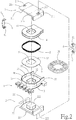
- the structure of a resonant transformer 1 of the present invention essentially includes: a core group 2, a secondary winding group 3, a primary winding group 4, a magnetic sheet 5 and two clips 6.
- the secondary winding group 3 includes a bobbin 31 having a first through hole 32.
- a wall plate 33 is provided around periphery of the top of the bobbin 31.
- a receiving space 36 is formed between the wall plate 33 and the top of the bobbin 31.
- a plurality of positioning columns 37 are provided at the bottom of the wall plate 33.
- a secondary coil 35 is wound inside the bobbin 31.
- the primary winding group 4 includes a second through hole 41, which is in communication with the first through hole 32.
- a primary coil 42 is wound inside the primary winding group 4.
- the magnetic sheet 5 includes a through hole 51, and a plurality of positioning notches 52 provided around the periphery of the magnetic sheet 5.
- the core group 2 includes a first core 21 and a second core 22 symmetrically disposed.
- Sidewalls 211 and 221 are provided at two ends of surfaces on one side of the first and second cores 21 and 22, respectively.
- Protrusions 212 and 222 are disposed between the sidewalls 211 and 221, respectively.
- Recesses 213 and 223 are provided at two ends of surfaces on the other side of the first and second cores 21 and 22, respectively.
- a hook 61 is disposed at each of two sides of each clip 6.
- the magnetic sheet 5 is placed on the bobbin 31 of the secondary winding group 3.
- placed on herein means that the magnetic sheet 5 can be placed on top of the bobbin 31 or inside the bobbin 31, or a plurality of magnetic sheets 5 are placed both on top and inside the bobbin 31.
- the magnetic sheet 5 is placed inside the receiving space 36 of the bobbin 31.
- the primary winding group 4 is placed inside the receiving space 36 and stacked on top of the magnetic sheet 5.
- the positioning columns 37 of the wall plate 33 are inserted in the positioning notches 52 around the magnetic sheet 5, so that the magnetic sheet 5 is secured inside the receiving space 36.
- the through hole 51 of the magnetic sheet 5, the first through hole 32 of the secondary winding group 3 and the second through hole 41 of the primary winding group 4 are in communication with each other.
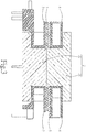
- the first core 21 is disposed on top of the primary winding group 4, while the second core 22 is disposed at the bottom of the primary winding group 4, meanwhile the sidewalls 211 and 221 of the first and second cores 21 and 22 covering the two sides of the secondary winding group 3, and the protrusions 212 and 222 of the first and second cores 21 and 22 passing through the first through hole 32, the second through hole 41 and the through hole 51, the core group 2 thus forms a complete magnetic path.
- the hooks 61 at either side of the clip 6 can be used to engage with the recesses 213 and 223 of the first and second cores 21 and 22, respectively, in order to facilitate the dismantling of the resonant transformer 1 for different magnetic sheets 5 with through holes 51 of different aperture.
- Magnetic flux that is connected with both the primary and secondary coils in a transformer is called the mutual flux (or main flux ⁇ 12 or ⁇ 21).
- main flux ⁇ 12 or ⁇ 21 there are primary leakage flux connected with only the primary but not the secondary coil (or self magnetic flux ⁇ 1), and secondary leakage flux connected with only the secondary but not the primary coil (or ⁇ 2). Since there is magnetic leakage in the transformer, leakage flux must exist.
- leakage flux is only connected with one of the primary and secondary coils, this implies that the inductance of each winding is included in its respective winding. Therefore, the primary leakage flux is the primary leakage inductance, and the secondary leakage flux is the secondary leakage inductance.
- the coupling coefficient be k
- the self inductance of the primary winding be LI
- the self inductance of the secondary winding be L2
- Le 2 1 ⁇ k . L 2
- the resonant transformer 1 of the present invention has different objective from a conventional transformer, it is characterized in that the leakage inductance can be stepless fine-tuned, and the magnitude of which can be designed entirely according to needs.
- the coupling coefficient is the key parameter that determines the magnitude of the leakage inductance.
- the coupling coefficient in a circuit, represents the level of coupling between elements, and the ratio of actual mutual inductance (absolute value) and the maximum between two inductors is defined as the coupling coefficient. Therefore, by incorporating the magnetic sheet 5 in the resonant transformer 1 of the present invention, the coupling coefficient between the secondary coil 35 and the primary coil 42 can be changed using the magnetic sheet 5.
- the magnetic sheet 5 is placed in the bobbin 3 of the secondary winding group 3, so that during operation of the resonant transformer 1, leakage inductance is produced due to magnetic interference of the magnetic sheet 5.
- the relationship between the leakage inductance created in the resonant transformer 1 and the magnetic sheet 5 is shown in FIG. 6 . It can been seen that the aperture of the through hole 51 of the magnetic sheet 5 is inversely proportional to the leakage inductance created in the resonant transformer 1. That is, the larger the through hole 51, the smaller the leakage inductance created in the resonant transformer 1, and vice versa.
- the thickness of the magnetic sheet 5 is proportional to the leakage inductance created in the resonant transformer 1, and the permeability of the magnetic sheet 5 is proportional to the leakage inductance created in the resonant transformer 1.
- the leakage inductance created in the resonant transformer 1 is very small, and the transformer can be used as a demagnetizing transformer.
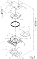
- FIGs. 4 and 5 an exploded view and a cross sectional view of a resonant transformer in accordance with another embodiment of the present invention are shown.
- this embodiment is characterized in that a slot 34 is provided in the bobbin 31 of the secondary winding group 3.
- a plurality of positioning columns 37 are provided inside the slot 34.
- the magnetic sheet 5 can be inserted into the slot 34.
- a plurality of magnetic sheets 5 can be provided with the secondary winding group 3.
- a receiving space 36 is provided on top of and a slot 34 is provided inside the bobbin 31 of the secondary winding group 3, and positioning columns 37 are disposed in the receiving space 36 and the slot 34. This is so that in the case where greater leakage inductance is needed, a plurality of magnetic sheets 5 can be placed in the receiving space 36 and the slot 34, allowing the resonant transformer 1 to create larger leakage inductance.
Landscapes
- Engineering & Computer Science (AREA)
- Power Engineering (AREA)
- Coils Or Transformers For Communication (AREA)
- Coils Of Transformers For General Uses (AREA)
Applications Claiming Priority (1)
| Application Number | Priority Date | Filing Date | Title |
|---|---|---|---|
| TW106106655A TWI616906B (zh) | 2017-03-01 | 2017-03-01 | Resonant transformer with leakage inductance adjustment |
Publications (2)
| Publication Number | Publication Date |
|---|---|
| EP3376512A1 true EP3376512A1 (de) | 2018-09-19 |
| EP3376512B1 EP3376512B1 (de) | 2022-04-06 |
Family
ID=60186529
Family Applications (1)
| Application Number | Title | Priority Date | Filing Date |
|---|---|---|---|
| EP18158621.5A Active EP3376512B1 (de) | 2017-03-01 | 2018-02-26 | Resonanter transformator mit einstellbarer streuinduktivität |
Country Status (4)
| Country | Link |
|---|---|
| US (1) | US10529483B2 (de) |
| EP (1) | EP3376512B1 (de) |
| JP (1) | JP2018148190A (de) |
| TW (1) | TWI616906B (de) |
Families Citing this family (9)
| Publication number | Priority date | Publication date | Assignee | Title |
|---|---|---|---|---|
| US10860614B2 (en) * | 2018-03-19 | 2020-12-08 | Landis+Gyr Innovations, Inc. | Partitioning data in a clustered database environment |
| ES1229314Y (es) | 2019-04-08 | 2019-08-05 | Premo Sa | Transformador para convertidores resonantes en configuracion zvs o llc |
| TWI724976B (zh) * | 2020-09-28 | 2021-04-11 | 昱京科技股份有限公司 | 薄型諧振變壓器漏感調整結構 |
| CN112185655B (zh) * | 2020-09-30 | 2022-01-25 | 昱京科技股份有限公司 | 薄型谐振变压器漏感调整结构 |
| CN113270259B (zh) * | 2021-06-18 | 2025-09-12 | 深圳莱福德科技股份有限公司 | 一种谐振变压器与开关电源电路 |
| US11842835B2 (en) * | 2021-12-08 | 2023-12-12 | Rompower Technology Holdings, Llc | High density magnetic structure |
| WO2024170065A1 (en) | 2022-02-14 | 2024-08-22 | Premo, Sl | A power electromagnetic device and fabrication method thereof |
| CN114639538B (zh) * | 2022-04-26 | 2022-09-06 | 杭州裕正电子有限公司 | 一种llc高频变压器及组装方法 |
| TWD227267S (zh) * | 2022-09-07 | 2023-09-01 | 昱京能源科技股份有限公司 | 鐵芯 |
Citations (8)
| Publication number | Priority date | Publication date | Assignee | Title |
|---|---|---|---|---|
| US20030038700A1 (en) * | 2001-08-21 | 2003-02-27 | Piechnick John Joseph | Low-power transformer for printed circuit boards |
| US20070216508A1 (en) * | 2006-03-17 | 2007-09-20 | Hon Hai Precision Industry Co., Ltd. | Transformer with adjustable leakage inductance and driving device using the same |
| TWM333646U (en) | 2007-12-17 | 2008-06-01 | Yao Sheng Electronic Co Ltd | Improved structure of leakage inductance resonant transformer |
| US20100253458A1 (en) * | 2009-04-01 | 2010-10-07 | Delta Electronics, Inc. | Transformer having leakage inductance |
| TWM416553U (en) | 2011-04-26 | 2011-11-21 | Ho-Yo Liao | The structure of two pieces of rim which are assembled together with hub motor |
| US20120154095A1 (en) * | 2010-08-26 | 2012-06-21 | Acbel Polytech Inc. | Symmetric planar transformer having adjustable leakage inductance |
| EP2779183A2 (de) * | 2013-03-13 | 2014-09-17 | Yujing Technology Co., Ltd. | Verbesserte Struktur eines Transformators |
| TWI556273B (zh) | 2015-10-14 | 2016-11-01 | Yujing Technology Co Ltd | Resonant High Current Density Transformer |
Family Cites Families (21)
| Publication number | Priority date | Publication date | Assignee | Title |
|---|---|---|---|---|
| JPS5337019U (de) * | 1976-09-07 | 1978-04-01 | ||
| JPS5599126U (de) * | 1978-12-28 | 1980-07-10 | ||
| JP2510366Y2 (ja) * | 1990-04-23 | 1996-09-11 | 日本電信電話株式会社 | 薄形トランス |
| JPH0555048A (ja) * | 1991-08-26 | 1993-03-05 | Sanken Electric Co Ltd | コイル装置 |
| US6774755B2 (en) * | 1996-10-24 | 2004-08-10 | Matsushita Electric Industrial Co., Ltd. | Choke coil |
| IL139714A0 (en) * | 2000-11-15 | 2002-02-10 | Payton Planar Magnetics Ltd | A bobbin for hybrid coils in planar magnetic components |
| KR100815890B1 (ko) * | 2001-03-31 | 2008-03-24 | 엘지.필립스 엘시디 주식회사 | 코일 권선방법과 이를 이용하여 코일이 권선된 트랜스포머및 액정표시장치의 인버터 |
| US7439838B2 (en) * | 2005-09-09 | 2008-10-21 | Delta Electronics, Inc. | Transformers and winding units thereof |
| JP2011035234A (ja) * | 2009-08-04 | 2011-02-17 | Japan Steel Works Ltd:The | コロナ放電処理装置用の高周波トランス |
| US20120001716A1 (en) * | 2010-07-02 | 2012-01-05 | Samsung Electro-Mechanics Co., Ltd. | Transformer |
| TWI445024B (zh) * | 2010-09-17 | 2014-07-11 | Chih Hao Lin | 非對稱式扁平變壓器 |
| CN102568782B (zh) * | 2010-12-20 | 2015-05-13 | 三星电机株式会社 | 变压器和包括该变压器的平板显示装置 |
| JP6132461B2 (ja) * | 2011-10-05 | 2017-05-24 | Tdk株式会社 | コイル部品 |
| JP2013172135A (ja) * | 2012-02-23 | 2013-09-02 | Fdk Corp | トランス |
| TWM438692U (en) * | 2012-05-09 | 2012-10-01 | Chicony Power Tech Co Ltd | Transformer with combined bobbin and transformer module having the same |
| US8922322B2 (en) * | 2012-08-31 | 2014-12-30 | Delta Electronics, Inc. | Combined structure of hollow bobbin and conductive sheet, hollow bobbin, and conductive sheet |
| TWI471879B (zh) * | 2012-10-22 | 2015-02-01 | Innotrans Technology Co Ltd | Combination transformer with leakage inductance adjustment function |
| TWI451457B (zh) * | 2013-05-03 | 2014-09-01 | Delta Electronics Inc | 初級側模組及其適用之變壓器 |
| JP2015153802A (ja) * | 2014-02-12 | 2015-08-24 | パナソニックIpマネジメント株式会社 | コイル構造体及び電力変換装置 |
| KR101610493B1 (ko) * | 2014-08-26 | 2016-04-07 | 현대자동차주식회사 | 변압기 냉각 장치 |
| TWM506359U (zh) * | 2014-11-14 | 2015-08-01 | Yujing Technology Co Ltd | 高功率變壓器改進結構 |
-
2017
- 2017-03-01 TW TW106106655A patent/TWI616906B/zh active
- 2017-04-26 US US15/497,272 patent/US10529483B2/en active Active
- 2017-05-17 JP JP2017097835A patent/JP2018148190A/ja active Pending
-
2018
- 2018-02-26 EP EP18158621.5A patent/EP3376512B1/de active Active
Patent Citations (8)
| Publication number | Priority date | Publication date | Assignee | Title |
|---|---|---|---|---|
| US20030038700A1 (en) * | 2001-08-21 | 2003-02-27 | Piechnick John Joseph | Low-power transformer for printed circuit boards |
| US20070216508A1 (en) * | 2006-03-17 | 2007-09-20 | Hon Hai Precision Industry Co., Ltd. | Transformer with adjustable leakage inductance and driving device using the same |
| TWM333646U (en) | 2007-12-17 | 2008-06-01 | Yao Sheng Electronic Co Ltd | Improved structure of leakage inductance resonant transformer |
| US20100253458A1 (en) * | 2009-04-01 | 2010-10-07 | Delta Electronics, Inc. | Transformer having leakage inductance |
| US20120154095A1 (en) * | 2010-08-26 | 2012-06-21 | Acbel Polytech Inc. | Symmetric planar transformer having adjustable leakage inductance |
| TWM416553U (en) | 2011-04-26 | 2011-11-21 | Ho-Yo Liao | The structure of two pieces of rim which are assembled together with hub motor |
| EP2779183A2 (de) * | 2013-03-13 | 2014-09-17 | Yujing Technology Co., Ltd. | Verbesserte Struktur eines Transformators |
| TWI556273B (zh) | 2015-10-14 | 2016-11-01 | Yujing Technology Co Ltd | Resonant High Current Density Transformer |
Also Published As
| Publication number | Publication date |
|---|---|
| TW201729225A (zh) | 2017-08-16 |
| US10529483B2 (en) | 2020-01-07 |
| EP3376512B1 (de) | 2022-04-06 |
| US20180254143A1 (en) | 2018-09-06 |
| TWI616906B (zh) | 2018-03-01 |
| JP2018148190A (ja) | 2018-09-20 |
Similar Documents
| Publication | Publication Date | Title |
|---|---|---|
| EP3376512B1 (de) | Resonanter transformator mit einstellbarer streuinduktivität | |
| US11961657B2 (en) | Multi-coil inductor | |
| US10218222B2 (en) | Non-contact charging module having a wireless charging coil and a magnetic sheet | |
| US11289252B2 (en) | Inductor and EMI filter including the same | |
| EP2797087B1 (de) | Magnetkern und magnetische Komponente damit | |
| US11398344B2 (en) | Transformer | |
| JP2015164395A (ja) | 共振子 | |
| CN110914938B (zh) | 平面型变压器和dcdc转换器 | |
| US20140176289A1 (en) | Electromagnetic interference filter and method of manufacturing the same | |
| US20220181986A1 (en) | Transformer and bidirectional isolated resonant converter | |
| US20120056707A1 (en) | Transformer for a power supply converter | |
| CN208478093U (zh) | 绕组结构的变压器 | |
| CN106575564A (zh) | 具有集成变换器的开关转换器电路 | |
| KR101545735B1 (ko) | 누설자속저감 권선법을 이용한 공진형 전력변환기용 변압기 | |
| WO2017138821A1 (en) | Resonant power transfer | |
| WO2020189351A1 (ja) | 非接触給電装置 | |
| CN107195448B (zh) | 具漏感调整的谐振变压器 | |
| JP2003022917A (ja) | インバータトランス | |
| JP2006108390A (ja) | トランスコア及びこれを用いたリーケージトランス | |
| KR102820938B1 (ko) | 인덕터 집적 평면형 변압기 | |
| TWM552661U (zh) | 具漏感調整的諧振變壓器 | |
| CN104752036A (zh) | 一种嵌有磁胶的变压器 | |
| RU116268U1 (ru) | Параметрический трансформатор | |
| KR20100137279A (ko) | 고주파 변압기 및 그 보빈 | |
| CN120824106A (zh) | 一种适用于llc和cllc电路的磁集成平面变压器 |
Legal Events
| Date | Code | Title | Description |
|---|---|---|---|
| PUAI | Public reference made under article 153(3) epc to a published international application that has entered the european phase |
Free format text: ORIGINAL CODE: 0009012 |
|
| STAA | Information on the status of an ep patent application or granted ep patent |
Free format text: STATUS: THE APPLICATION HAS BEEN PUBLISHED |
|
| AK | Designated contracting states |
Kind code of ref document: A1 Designated state(s): AL AT BE BG CH CY CZ DE DK EE ES FI FR GB GR HR HU IE IS IT LI LT LU LV MC MK MT NL NO PL PT RO RS SE SI SK SM TR |
|
| AX | Request for extension of the european patent |
Extension state: BA ME |
|
| STAA | Information on the status of an ep patent application or granted ep patent |
Free format text: STATUS: REQUEST FOR EXAMINATION WAS MADE |
|
| 17P | Request for examination filed |
Effective date: 20190318 |
|
| RBV | Designated contracting states (corrected) |
Designated state(s): AL AT BE BG CH CY CZ DE DK EE ES FI FR GB GR HR HU IE IS IT LI LT LU LV MC MK MT NL NO PL PT RO RS SE SI SK SM TR |
|
| GRAP | Despatch of communication of intention to grant a patent |
Free format text: ORIGINAL CODE: EPIDOSNIGR1 |
|
| STAA | Information on the status of an ep patent application or granted ep patent |
Free format text: STATUS: GRANT OF PATENT IS INTENDED |
|
| INTG | Intention to grant announced |
Effective date: 20210729 |
|
| GRAS | Grant fee paid |
Free format text: ORIGINAL CODE: EPIDOSNIGR3 |
|
| GRAA | (expected) grant |
Free format text: ORIGINAL CODE: 0009210 |
|
| STAA | Information on the status of an ep patent application or granted ep patent |
Free format text: STATUS: THE PATENT HAS BEEN GRANTED |
|
| AK | Designated contracting states |
Kind code of ref document: B1 Designated state(s): AL AT BE BG CH CY CZ DE DK EE ES FI FR GB GR HR HU IE IS IT LI LT LU LV MC MK MT NL NO PL PT RO RS SE SI SK SM TR |
|
| REG | Reference to a national code |
Ref country code: GB Ref legal event code: FG4D |
|
| REG | Reference to a national code |
Ref country code: CH Ref legal event code: EP |
|
| REG | Reference to a national code |
Ref country code: AT Ref legal event code: REF Ref document number: 1461301 Country of ref document: AT Kind code of ref document: T Effective date: 20220115 |
|
| PUAC | Information related to the publication of a b1 document modified or deleted |
Free format text: ORIGINAL CODE: 0009299EPPU |
|
| STAA | Information on the status of an ep patent application or granted ep patent |
Free format text: STATUS: GRANT OF PATENT IS INTENDED |
|
| REG | Reference to a national code |
Ref country code: DE Ref legal event code: R096 Ref document number: 602018028993 Country of ref document: DE |
|
| REG | Reference to a national code |
Ref country code: CH Ref legal event code: PK Free format text: DIE ERTEILUNG WURDE VOM EPA WIDERRUFEN. |
|
| REG | Reference to a national code |
Ref country code: IE Ref legal event code: FG4D |
|
| DB1 | Publication of patent cancelled |
Effective date: 20220121 |
|
| GRAA | (expected) grant |
Free format text: ORIGINAL CODE: 0009210 |
|
| STAA | Information on the status of an ep patent application or granted ep patent |
Free format text: STATUS: THE PATENT HAS BEEN GRANTED |
|
| REG | Reference to a national code |
Ref country code: DE Ref legal event code: R107 Ref document number: 602018028993 Country of ref document: DE |
|
| AK | Designated contracting states |
Kind code of ref document: B1 Designated state(s): AL AT BE BG CH CY CZ DE DK EE ES FI FR GB GR HR HU IE IS IT LI LT LU LV MC MK MT NL NO PL PT RO RS SE SI SK SM TR |
|
| REG | Reference to a national code |
Ref country code: GB Ref legal event code: FG4D |
|
| REG | Reference to a national code |
Ref country code: CH Ref legal event code: PK Free format text: DIE ERTEILUNG VOM 05.01.2022 WURDE VOM EPA WIDERRUFEN. Ref country code: CH Ref legal event code: EP |
|
| REG | Reference to a national code |
Ref country code: AT Ref legal event code: REF Ref document number: 1461301 Country of ref document: AT Kind code of ref document: T Effective date: 20220415 |
|
| REG | Reference to a national code |
Ref country code: DE Ref legal event code: R096 Ref document number: 602018028993 Country of ref document: DE |
|
| REG | Reference to a national code |
Ref country code: NL Ref legal event code: FP |
|
| REG | Reference to a national code |
Ref country code: LT Ref legal event code: MG9D |
|
| PG25 | Lapsed in a contracting state [announced via postgrant information from national office to epo] |
Ref country code: RS Free format text: LAPSE BECAUSE OF FAILURE TO SUBMIT A TRANSLATION OF THE DESCRIPTION OR TO PAY THE FEE WITHIN THE PRESCRIBED TIME-LIMIT Effective date: 20220406 |
|
| PG25 | Lapsed in a contracting state [announced via postgrant information from national office to epo] |
Ref country code: GR Free format text: LAPSE BECAUSE OF FAILURE TO SUBMIT A TRANSLATION OF THE DESCRIPTION OR TO PAY THE FEE WITHIN THE PRESCRIBED TIME-LIMIT Effective date: 20220406 |
|
| REG | Reference to a national code |
Ref country code: AT Ref legal event code: MK05 Ref document number: 1461301 Country of ref document: AT Kind code of ref document: T Effective date: 20220406 |
|
| PG25 | Lapsed in a contracting state [announced via postgrant information from national office to epo] |
Ref country code: IS Free format text: LAPSE BECAUSE OF FAILURE TO SUBMIT A TRANSLATION OF THE DESCRIPTION OR TO PAY THE FEE WITHIN THE PRESCRIBED TIME-LIMIT Effective date: 20220505 |
|
| PG25 | Lapsed in a contracting state [announced via postgrant information from national office to epo] |
Ref country code: PT Free format text: LAPSE BECAUSE OF FAILURE TO SUBMIT A TRANSLATION OF THE DESCRIPTION OR TO PAY THE FEE WITHIN THE PRESCRIBED TIME-LIMIT Effective date: 20220808 Ref country code: NO Free format text: LAPSE BECAUSE OF FAILURE TO SUBMIT A TRANSLATION OF THE DESCRIPTION OR TO PAY THE FEE WITHIN THE PRESCRIBED TIME-LIMIT Effective date: 20220706 Ref country code: LT Free format text: LAPSE BECAUSE OF FAILURE TO SUBMIT A TRANSLATION OF THE DESCRIPTION OR TO PAY THE FEE WITHIN THE PRESCRIBED TIME-LIMIT Effective date: 20220406 Ref country code: HR Free format text: LAPSE BECAUSE OF FAILURE TO SUBMIT A TRANSLATION OF THE DESCRIPTION OR TO PAY THE FEE WITHIN THE PRESCRIBED TIME-LIMIT Effective date: 20220406 Ref country code: FI Free format text: LAPSE BECAUSE OF FAILURE TO SUBMIT A TRANSLATION OF THE DESCRIPTION OR TO PAY THE FEE WITHIN THE PRESCRIBED TIME-LIMIT Effective date: 20220406 Ref country code: ES Free format text: LAPSE BECAUSE OF FAILURE TO SUBMIT A TRANSLATION OF THE DESCRIPTION OR TO PAY THE FEE WITHIN THE PRESCRIBED TIME-LIMIT Effective date: 20220406 Ref country code: BG Free format text: LAPSE BECAUSE OF FAILURE TO SUBMIT A TRANSLATION OF THE DESCRIPTION OR TO PAY THE FEE WITHIN THE PRESCRIBED TIME-LIMIT Effective date: 20220706 Ref country code: AT Free format text: LAPSE BECAUSE OF FAILURE TO SUBMIT A TRANSLATION OF THE DESCRIPTION OR TO PAY THE FEE WITHIN THE PRESCRIBED TIME-LIMIT Effective date: 20220406 |
|
| PG25 | Lapsed in a contracting state [announced via postgrant information from national office to epo] |
Ref country code: PL Free format text: LAPSE BECAUSE OF NON-PAYMENT OF DUE FEES Effective date: 20220406 Ref country code: LV Free format text: LAPSE BECAUSE OF FAILURE TO SUBMIT A TRANSLATION OF THE DESCRIPTION OR TO PAY THE FEE WITHIN THE PRESCRIBED TIME-LIMIT Effective date: 20220406 |
|
| REG | Reference to a national code |
Ref country code: DE Ref legal event code: R097 Ref document number: 602018028993 Country of ref document: DE |
|
| PG25 | Lapsed in a contracting state [announced via postgrant information from national office to epo] |
Ref country code: SM Free format text: LAPSE BECAUSE OF FAILURE TO SUBMIT A TRANSLATION OF THE DESCRIPTION OR TO PAY THE FEE WITHIN THE PRESCRIBED TIME-LIMIT Effective date: 20220406 Ref country code: SK Free format text: LAPSE BECAUSE OF FAILURE TO SUBMIT A TRANSLATION OF THE DESCRIPTION OR TO PAY THE FEE WITHIN THE PRESCRIBED TIME-LIMIT Effective date: 20220406 Ref country code: RO Free format text: LAPSE BECAUSE OF FAILURE TO SUBMIT A TRANSLATION OF THE DESCRIPTION OR TO PAY THE FEE WITHIN THE PRESCRIBED TIME-LIMIT Effective date: 20220406 Ref country code: MC Free format text: LAPSE BECAUSE OF FAILURE TO SUBMIT A TRANSLATION OF THE DESCRIPTION OR TO PAY THE FEE WITHIN THE PRESCRIBED TIME-LIMIT Effective date: 20220406 Ref country code: EE Free format text: LAPSE BECAUSE OF FAILURE TO SUBMIT A TRANSLATION OF THE DESCRIPTION OR TO PAY THE FEE WITHIN THE PRESCRIBED TIME-LIMIT Effective date: 20220406 Ref country code: DK Free format text: LAPSE BECAUSE OF FAILURE TO SUBMIT A TRANSLATION OF THE DESCRIPTION OR TO PAY THE FEE WITHIN THE PRESCRIBED TIME-LIMIT Effective date: 20220406 Ref country code: CZ Free format text: LAPSE BECAUSE OF FAILURE TO SUBMIT A TRANSLATION OF THE DESCRIPTION OR TO PAY THE FEE WITHIN THE PRESCRIBED TIME-LIMIT Effective date: 20220406 |
|
| PLBE | No opposition filed within time limit |
Free format text: ORIGINAL CODE: 0009261 |
|
| STAA | Information on the status of an ep patent application or granted ep patent |
Free format text: STATUS: NO OPPOSITION FILED WITHIN TIME LIMIT |
|
| 26N | No opposition filed |
Effective date: 20230110 |
|
| PG25 | Lapsed in a contracting state [announced via postgrant information from national office to epo] |
Ref country code: AL Free format text: LAPSE BECAUSE OF FAILURE TO SUBMIT A TRANSLATION OF THE DESCRIPTION OR TO PAY THE FEE WITHIN THE PRESCRIBED TIME-LIMIT Effective date: 20220406 |
|
| PG25 | Lapsed in a contracting state [announced via postgrant information from national office to epo] |
Ref country code: SI Free format text: LAPSE BECAUSE OF FAILURE TO SUBMIT A TRANSLATION OF THE DESCRIPTION OR TO PAY THE FEE WITHIN THE PRESCRIBED TIME-LIMIT Effective date: 20220406 |
|
| REG | Reference to a national code |
Ref country code: CH Ref legal event code: PL |
|
| REG | Reference to a national code |
Ref country code: BE Ref legal event code: MM Effective date: 20230228 |
|
| GBPC | Gb: european patent ceased through non-payment of renewal fee |
Effective date: 20230226 |
|
| PG25 | Lapsed in a contracting state [announced via postgrant information from national office to epo] |
Ref country code: LU Free format text: LAPSE BECAUSE OF NON-PAYMENT OF DUE FEES Effective date: 20230226 Ref country code: LI Free format text: LAPSE BECAUSE OF NON-PAYMENT OF DUE FEES Effective date: 20230228 Ref country code: CH Free format text: LAPSE BECAUSE OF NON-PAYMENT OF DUE FEES Effective date: 20230228 |
|
| REG | Reference to a national code |
Ref country code: IE Ref legal event code: MM4A |
|
| PG25 | Lapsed in a contracting state [announced via postgrant information from national office to epo] |
Ref country code: GB Free format text: LAPSE BECAUSE OF NON-PAYMENT OF DUE FEES Effective date: 20230226 |
|
| PG25 | Lapsed in a contracting state [announced via postgrant information from national office to epo] |
Ref country code: IE Free format text: LAPSE BECAUSE OF NON-PAYMENT OF DUE FEES Effective date: 20230226 Ref country code: GB Free format text: LAPSE BECAUSE OF NON-PAYMENT OF DUE FEES Effective date: 20230226 |
|
| PG25 | Lapsed in a contracting state [announced via postgrant information from national office to epo] |
Ref country code: BE Free format text: LAPSE BECAUSE OF NON-PAYMENT OF DUE FEES Effective date: 20230228 |
|
| PG25 | Lapsed in a contracting state [announced via postgrant information from national office to epo] |
Ref country code: BG Free format text: LAPSE BECAUSE OF FAILURE TO SUBMIT A TRANSLATION OF THE DESCRIPTION OR TO PAY THE FEE WITHIN THE PRESCRIBED TIME-LIMIT Effective date: 20220406 |
|
| PG25 | Lapsed in a contracting state [announced via postgrant information from national office to epo] |
Ref country code: BG Free format text: LAPSE BECAUSE OF FAILURE TO SUBMIT A TRANSLATION OF THE DESCRIPTION OR TO PAY THE FEE WITHIN THE PRESCRIBED TIME-LIMIT Effective date: 20220406 |
|
| PG25 | Lapsed in a contracting state [announced via postgrant information from national office to epo] |
Ref country code: CY Free format text: LAPSE BECAUSE OF FAILURE TO SUBMIT A TRANSLATION OF THE DESCRIPTION OR TO PAY THE FEE WITHIN THE PRESCRIBED TIME-LIMIT; INVALID AB INITIO Effective date: 20180226 |
|
| PG25 | Lapsed in a contracting state [announced via postgrant information from national office to epo] |
Ref country code: HU Free format text: LAPSE BECAUSE OF FAILURE TO SUBMIT A TRANSLATION OF THE DESCRIPTION OR TO PAY THE FEE WITHIN THE PRESCRIBED TIME-LIMIT; INVALID AB INITIO Effective date: 20180226 |
|
| PG25 | Lapsed in a contracting state [announced via postgrant information from national office to epo] |
Ref country code: TR Free format text: LAPSE BECAUSE OF FAILURE TO SUBMIT A TRANSLATION OF THE DESCRIPTION OR TO PAY THE FEE WITHIN THE PRESCRIBED TIME-LIMIT Effective date: 20220406 |
|
| PG25 | Lapsed in a contracting state [announced via postgrant information from national office to epo] |
Ref country code: SE Free format text: LAPSE BECAUSE OF FAILURE TO SUBMIT A TRANSLATION OF THE DESCRIPTION OR TO PAY THE FEE WITHIN THE PRESCRIBED TIME-LIMIT Effective date: 20220406 |
|
| PGFP | Annual fee paid to national office [announced via postgrant information from national office to epo] |
Ref country code: NL Payment date: 20260218 Year of fee payment: 9 |
|
| PGFP | Annual fee paid to national office [announced via postgrant information from national office to epo] |
Ref country code: DE Payment date: 20260218 Year of fee payment: 9 |
|
| PGFP | Annual fee paid to national office [announced via postgrant information from national office to epo] |
Ref country code: IT Payment date: 20260224 Year of fee payment: 9 |
|
| PGFP | Annual fee paid to national office [announced via postgrant information from national office to epo] |
Ref country code: FR Payment date: 20260218 Year of fee payment: 9 |