EP2779183A2 - Verbesserte Struktur eines Transformators - Google Patents
Verbesserte Struktur eines Transformators Download PDFInfo
- Publication number
- EP2779183A2 EP2779183A2 EP20140159430 EP14159430A EP2779183A2 EP 2779183 A2 EP2779183 A2 EP 2779183A2 EP 20140159430 EP20140159430 EP 20140159430 EP 14159430 A EP14159430 A EP 14159430A EP 2779183 A2 EP2779183 A2 EP 2779183A2
- Authority
- EP
- European Patent Office
- Prior art keywords
- lead frame
- transformer
- main body
- furnished
- improved structure
- Prior art date
- Legal status (The legal status is an assumption and is not a legal conclusion. Google has not performed a legal analysis and makes no representation as to the accuracy of the status listed.)
- Granted
Links
Images


Classifications
-
- H—ELECTRICITY
- H01—ELECTRIC ELEMENTS
- H01F—MAGNETS; INDUCTANCES; TRANSFORMERS; SELECTION OF MATERIALS FOR THEIR MAGNETIC PROPERTIES
- H01F27/00—Details of transformers or inductances, in general
- H01F27/24—Magnetic cores
-
- H—ELECTRICITY
- H01—ELECTRIC ELEMENTS
- H01F—MAGNETS; INDUCTANCES; TRANSFORMERS; SELECTION OF MATERIALS FOR THEIR MAGNETIC PROPERTIES
- H01F27/00—Details of transformers or inductances, in general
- H01F27/28—Coils; Windings; Conductive connections
- H01F27/2866—Combination of wires and sheets
-
- H—ELECTRICITY
- H01—ELECTRIC ELEMENTS
- H01F—MAGNETS; INDUCTANCES; TRANSFORMERS; SELECTION OF MATERIALS FOR THEIR MAGNETIC PROPERTIES
- H01F27/00—Details of transformers or inductances, in general
- H01F27/28—Coils; Windings; Conductive connections
- H01F27/30—Fastening or clamping coils, windings, or parts thereof together; Fastening or mounting coils or windings on core, casing, or other support
- H01F27/306—Fastening or mounting coils or windings on core, casing or other support
-
- H—ELECTRICITY
- H01—ELECTRIC ELEMENTS
- H01F—MAGNETS; INDUCTANCES; TRANSFORMERS; SELECTION OF MATERIALS FOR THEIR MAGNETIC PROPERTIES
- H01F27/00—Details of transformers or inductances, in general
- H01F27/24—Magnetic cores
- H01F27/26—Fastening parts of the core together; Fastening or mounting the core on casing or support
- H01F27/263—Fastening parts of the core together
-
- H—ELECTRICITY
- H01—ELECTRIC ELEMENTS
- H01F—MAGNETS; INDUCTANCES; TRANSFORMERS; SELECTION OF MATERIALS FOR THEIR MAGNETIC PROPERTIES
- H01F27/00—Details of transformers or inductances, in general
- H01F27/28—Coils; Windings; Conductive connections
- H01F27/32—Insulating of coils, windings, or parts thereof
- H01F27/324—Insulation between coil and core, between different winding sections, around the coil; Other insulation structures
- H01F27/325—Coil bobbins
Definitions
- the invention relates to an improved structure of transformer, and more particularly, to an improved structure of transformer making use of a trouser-like flap furnished by fitting to the main core part of the iron core to form the transformer's secondary winding.
- transformers of the prior art are coil type transformer which employs two wires (enamel covered wire) to wind around a same iron core forming a primary winding to be connected to a power source and a secondary winding to be connected to a load.
- the relation for generating induction voltage depends on the secondary-to-primary-turn ratio.
- FIG. 1 is an isometric exploded view of the structure the transformer employing metal strips to be a secondary winding of the prior art
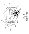
- FIG. 2 is an outward appearance of the assembled structure the transformer of the prior art.
- the transformer structure of the prior art mainly includes a lead frame (9), two oppositely combined iron cores (7), and a plurality of thin metal strips (8), each of them with a thickness of 10 ⁇ m ⁇ 100 ⁇ m.
- Each of the metal strips (8) has a main core part (71) and four side wing parts (72) with side openings (74) provided in between thereof.
- the lead frame (9) having a penetration hole (91) furnished at the center thereof for slipping on the main core part (71) is contained in the containing space (73) of the iron core (7).
- the lead frame (9) also has a bobbin furnished at the mid-section of the outer circumference thereof for the primary winding (92) (coil) to be wound with a positioning part (931) defined by upper-and-lower partitioned plates (93) that has a wire connecting seats (94) furnished at an end corner thereof and capable of stretching out of the iron core (7) through the side openings (74).
- each of the metal strips (8) has a hollow part (81) that is furnished at the center thereof, and is capable of slipping on the positioning parts (931) making all of the metal strips (8) axially stack up.
- each of the metal strips (8) has an opening gap (82) at a corner thereof having extended polar legs (83) capable of stretching out of the iron core (7) through the side opening (74).
- a plurality of partitioning metal strips (84) are placed in between the metal strips (8) making each of the metal strip (8) form a secondary winding.
- This kind of stacking up metal strips (8) and partitioning metal strips (84) is capable of lowering the eddy current loss in practical application. However, it will result in having relatively larger overall induction loss.
- FIG. 3 is an isometric exploded view of another structure the transformer employing metal strips to be a secondary winding of the prior art while FIG. 4 is an outward appearance of the assembled structure the transformer shown in FIG. 3 of the prior art.
- the transformer structure of the prior art mainly includes a lead frame (90), a plurality of metal strips (80) having thickness from tens of mini meters to hundreds of mini meters, and a pair of oppositely combined E-shaped iron cores (70).
- the lead frame (90) has a transversely stretching penetration hole (901) with a plurality of slots (902) furnished at the periphery thereof for providing a primary winding (903) (coil).
- the lead frame (90) has wire connecting seats (904) formed at both ends of the penetration hole (901) where one of the wire connecting seats (904) has wire connecting posts (905) connected to both ends of the primary winding (903).
- the metal strips (80) being in inverse U-shape are arranged in the direction parallel to the axis of the penetration hole (901) to cover all the plurality of slots (902) at the outer circumference C the primary winding (903) may be wound around the outer circumference of the metal strips (80) so as to form a sandwich winding and form polar legs (801) stretched in the same direction as those of the wire connecting posts (905) at both ends of the metal strips (80).
- a cap (802) having an appropriate containing space (803) and a pair of side penetration holes (804) corresponding to the penetration hole (901) is employed to cover the lead frame (90) and the metal strips (80).
- the pair of oppositely combined E-shaped iron cores (70) has their central main core parts stretch through both of the side penetration holes (804) respectively of the cape (802) to be contacted each other so as to form another transformer making use of the metal strips (80) to be a secondary winding.
- this kind of structure having each of the metal strips (80) furnished in the direction of the main core part of the E-shaped iron cores (70) is capable of effectively diminishing induction loss.
- the metal strips (80) having the characteristic of not being bendable with structural products appeared in horizontally rather than vertically stacking up has seriously affected the diversity and competitiveness of transformer product.
- the invention provides an improved structure of transformer that is capable of overcoming the shortcomings of the prior art, satisfying the requirements of the industry, as well as improving the competitiveness in the market. It aims to ameliorate at least some of the disadvantages of the prior art or to provide a useful alternative.
- the primary objective of the invention is to provide an improved structure of transformer making use of the convenience of a design of a removable and separable lead frame cover to provide a secondary winding formed by trouser-like flap to be assembled in a lead frame main body so as to form a trouser-like flap furnished by fitting to the main core part of the iron core where the main core part of the iron core is an uprightly stretching transformer structure to achieve the diversity and competitiveness of transformer product.
- the secondary objective of the invention is to provide an improved structure of transformer by making use of a secondary winding design of an integrally formed trouser-like flap that is capable of effectively simplifying the manufacturing process and lowing production cost.
- an improved structure of transformer is provided to include a lead frame main body, a lead frame cover, a trouser-like flap, and two iron cores where the lead frame main body has a penetration hole with a bobbin formed at the circumference there around.
- the trouser-like flap being made of metal has a hollow part for slipping on a bobbin of the lead frame main body also includes horizontally stretched thigh parts.
- the outer circumference of the trouser-like flap is furnished with a primary winding.
- the lead frame cover being a sheet-shaped body has a hollow hole furnished at the center thereof, and on the inner-side surface, each of the two iron core has a main core part capable of stretching through the penetration hole of the lead frame main body where the main core part has a containing circumferential trench capable of containing the lead frame main body, wherein the containing circumferential trench also has a pair of oppositely disposed side openings for being stretched through by the wire connecting seats.
- a primary winding is furnished around the outer circumference of the trouser-like flap.
- the primary winding is wound by enamel covered wire.
- the trouser-like flap also includes horizontally stretched thigh parts having wire connecting legs stretched in the axial direction of the trouser-like flap and through the breaches.
- the wire connecting seat has a plurality of primary winding conducting post while the wire connecting seats has a plurality of spare conductance posts, and the two end parts of the primary winding are connected to the primary winding conducting post.
- two oppositely disposed combining part are furnished at the circumference of the bobbin of the lead frame main body while the inner circumference of the hollow hole of the lead frame cover has at least two to-be-combined parts corresponding to the combining parts to make the lead frame cover and lead frame main body form secure combination.
- the combining parts are hook parts while the to-be-combined parts are adverse hook parts.
- the lead frame main body has a plurality of fillet and rounds furnished and for being stopped at the circumference of the bobbin at the side of the circumference of the lead frame cover.
- a pair of oppositely disposed clip-receiving recesses furnished on the outer- side surface of the iron cores are provided for being clipped by a pair of clip fasteners making the two iron cores maintain a secure combination.
- a plurality of partitioned clip slots of lead frame cover are furnished to correspond to the two edges of the wire connecting seats of the lead frame main body.
- FIG. 5 is an isometric exploded view of the improved structure the transformer of the invention.
- the improved structure the transformer of the invention includes a lead frame main body (1), a lead frame cover (2), a trouser-like flap (3), and two iron cores (4).
- the lead frame main body (1) is a tube body having a penetration hole (11) with a bobbin (12) formed at the circumference there around where the four corners of the bobbin (12) are fillet and rounds (121).
- the lead frame main body (1) has two oppositely disposed wire connecting seats (13), (14) where the wire connecting seat (13) has a plurality of primary winding conducting post (131) while the wire connecting seats (14) has a plurality of spare conductance posts (143) and two breaches (141), (142) furnished thereof. Moreover, two oppositely disposed combining parts (122) which can also be hook parts are furnished at the circumference of the bobbin (12) of the lead frame main body (1).
- the trouser-like flap (3) being made of metal has a hollow part (31) for slipping on a bobbin (121) of the lead frame main body (1).
- the trouser-like flap (3) also includes horizontally stretched thigh parts (32), (33) having wire connecting legs (321), (331) stretched in the axial direction of the trouser-like flap (3).
- the lead frame cover (2) being a sheet-shaped body has a hollow hole (21) furnished at the center thereof and is corresponding to the penetration hole (11) where the inner circumference of the hollow hole (21) has at least two to-be-combined parts (22) (which can also be adverse hook parts) corresponding to the combining parts (122) (which can also be hook parts). Moreover, the lead frame cover (2) has a plurality of clip slots (23) furnished on the two side edges that are corresponding to the wire connecting seats (13), (14) of the lead frame main body (1).
- the iron core (4) has a main core part (41) capable of stretching through the penetration hole (11) of the lead frame main body (1) where the main core part (41) has a pair of oppositely disposed side wing parts (42) furnished on the outer edge thereof, and also has a containing circumferential trench (43) capable of containing the lead frame main body (1) and formed between the main core part (41) and the side wing part (42). What is more, the containing circumferential trench (43) also has a pair of oppositely disposed side openings (44), (45).
- the iron core (4) has a pair of oppositely disposed clip-receiving recesses (46).
- FIG. 6 is an isometric view of the assembled structure of the lead frame and the coil of the improved structure of transformer of the invention
- FIG. 7 is an isometric view of a part of the assembled structure of the improved structure of transformer of the invention
- FIG. 8 is an isometric view of an outward appearance of the overall assembled structure of the improved structure of transformer of the invention. As shown in Fig. 6 , FIG.7 , and FIG.
- the hollow part (31) of the trouser-like flap (3) is slipped on the circumference of the bobbin (12) of the lead frame main body (1), and in the mean time, the wire-connecting ends (321), (331) are stretched through the breaches (141), (142) toward the same directions of the second pivotally-connected part (241) and primary winding conducting post (131) respectively.
- the lead frame cover (2) is covered on the lead frame main body (1) with the combining parts (122) (hook parts) hooked to the to-be-combined parts (22) (can be adverse hook parts) to make the lead frame cover (2) and lead frame main body (1) not only form secure combination but also limit the trouser-like flap (3) from being come off.
- the outer circumference of the trouser-like flap (3) is wound to form a primary winding (123) by employing enamel covered wire, and is additionally wound to form a control winding (not shown in the Figure) as it is required making both end parts of both the primary winding (123) and the control winding being embedded into various clip slots (23) respectively to form temporary positioning.
- the main core part (41) is stretched through the penetration hole (11) of the lead frame main body (1) making the top-and-bottom iron core (4) contact together.
- the wire connecting seats (13), (14) of the lead frame main body (1) are stretched outward through the side openings (44), (45) respectively, and by employing the clip fastener (47) to clip the top-and bottom iron cores (4) together in secure combination condition by having the clip fastener (47) fasten in the clip-receiving recesses (46).
- the overall assembly of the transformer is achieved by having the two end parts of the primary winding (123) be brazed with the primary winding conducting post (131) and the two end parts of the control winding be brazed with the each of the spare conductance posts (143).
- the design of employing the trouser-like flap (3) to cover the bobbin (12) and the main core part (41) of the iron core (4) of the improved structure of the invention is capable of effectively lowering the penetration area of magnetic leakage, diminishing Eddy current loss, and lowering the copper loss, and further achieving the efficacy of carried direct current.
- the improved structure of transformer of the invention is capable of surely simplifying its structure and assembling process, and producing a transformer having the efficacy of transformer with secondary winding of the trouser-like flap (3) that is covered in the direction of the main core part (41) of the iron core (4), making the improved structure of transformer of the invention meet the conditions of patentability.
Landscapes
- Engineering & Computer Science (AREA)
- Power Engineering (AREA)
- Coils Of Transformers For General Uses (AREA)
- Coils Or Transformers For Communication (AREA)
Applications Claiming Priority (1)
| Application Number | Priority Date | Filing Date | Title |
|---|---|---|---|
| TW102108769A TWI438794B (zh) | 2013-03-13 | 2013-03-13 | The improved structure of the transformer |
Publications (3)
| Publication Number | Publication Date |
|---|---|
| EP2779183A2 true EP2779183A2 (de) | 2014-09-17 |
| EP2779183A3 EP2779183A3 (de) | 2015-05-20 |
| EP2779183B1 EP2779183B1 (de) | 2018-02-21 |
Family
ID=49479083
Family Applications (1)
| Application Number | Title | Priority Date | Filing Date |
|---|---|---|---|
| EP14159430.9A Active EP2779183B1 (de) | 2013-03-13 | 2014-03-13 | Verbesserte Struktur eines Transformators |
Country Status (4)
| Country | Link |
|---|---|
| US (1) | US9105390B2 (de) |
| EP (1) | EP2779183B1 (de) |
| JP (1) | JP3190474U (de) |
| TW (1) | TWI438794B (de) |
Cited By (1)
| Publication number | Priority date | Publication date | Assignee | Title |
|---|---|---|---|---|
| EP3376512A1 (de) * | 2017-03-01 | 2018-09-19 | Yujing Technology Co., Ltd. | Resonanter transformator mit einstellbarer streuinduktivität |
Families Citing this family (7)
| Publication number | Priority date | Publication date | Assignee | Title |
|---|---|---|---|---|
| TWI463508B (zh) * | 2014-04-22 | 2014-12-01 | Yujing Technology Co Ltd | The improved structure of the transformer |
| TWI556273B (zh) * | 2015-10-14 | 2016-11-01 | Yujing Technology Co Ltd | Resonant High Current Density Transformer |
| JP6631274B2 (ja) * | 2016-01-26 | 2020-01-15 | Tdk株式会社 | 巻線部品 |
| US10998124B2 (en) * | 2016-05-06 | 2021-05-04 | Vishay Dale Electronics, Llc | Nested flat wound coils forming windings for transformers and inductors |
| JP7269699B2 (ja) * | 2017-07-27 | 2023-05-09 | 富士電機株式会社 | コア、トランス |
| US11670448B2 (en) * | 2018-05-07 | 2023-06-06 | Astronics Advanced Electronic Systems Corp. | System of termination of high power transformers for reduced AC termination loss at high frequency |
| US20230223187A1 (en) * | 2022-01-11 | 2023-07-13 | Cyntec Co., Ltd. | Magnetic component |
Family Cites Families (13)
| Publication number | Priority date | Publication date | Assignee | Title |
|---|---|---|---|---|
| GB864046A (en) * | 1959-01-07 | 1961-03-29 | Philips Electrical Ind Ltd | Improvements in or relating to low-power transformers |
| US4176335A (en) * | 1977-10-25 | 1979-11-27 | Burroughs Corporation | Electrical conducting apparatus |
| US5748064A (en) * | 1996-02-22 | 1998-05-05 | Northrop Grumman Corporation | Low profile reactor |
| JP2003324017A (ja) * | 2002-04-30 | 2003-11-14 | Koito Mfg Co Ltd | トランス |
| EP1547104B1 (de) * | 2002-10-01 | 2010-12-08 | DET International Holding Limited | Spulenkörper |
| DE102004006712B4 (de) * | 2004-02-11 | 2006-08-31 | Tyco Electronics Amp Gmbh | Spulenkörper für einen elektromechanischen Aktor |
| US7439838B2 (en) * | 2005-09-09 | 2008-10-21 | Delta Electronics, Inc. | Transformers and winding units thereof |
| TWI316725B (en) * | 2006-08-31 | 2009-11-01 | Delta Electronics Inc | Transformer structure and manufacturing method thereof |
| TW200820278A (en) * | 2006-10-16 | 2008-05-01 | Delta Electronics Inc | Transformer |
| TW200832460A (en) * | 2007-01-31 | 2008-08-01 | Delta Electronics Inc | Transformer structure |
| JP4980196B2 (ja) * | 2007-10-25 | 2012-07-18 | 太陽誘電株式会社 | 電源用トランス |
| US8102237B2 (en) * | 2008-06-12 | 2012-01-24 | Power Integrations, Inc. | Low profile coil-wound bobbin |
| TWM411647U (en) * | 2011-01-14 | 2011-09-11 | Yujing Technology Co Ltd | Dual-face secondary-side lamination transformer |
-
2013
- 2013-03-13 TW TW102108769A patent/TWI438794B/zh active
-
2014
- 2014-01-10 JP JP2014000086U patent/JP3190474U/ja not_active Expired - Lifetime
- 2014-03-12 US US14/206,165 patent/US9105390B2/en active Active
- 2014-03-13 EP EP14159430.9A patent/EP2779183B1/de active Active
Non-Patent Citations (1)
| Title |
|---|
| None |
Cited By (1)
| Publication number | Priority date | Publication date | Assignee | Title |
|---|---|---|---|---|
| EP3376512A1 (de) * | 2017-03-01 | 2018-09-19 | Yujing Technology Co., Ltd. | Resonanter transformator mit einstellbarer streuinduktivität |
Also Published As
| Publication number | Publication date |
|---|---|
| EP2779183A3 (de) | 2015-05-20 |
| JP3190474U (ja) | 2014-05-15 |
| US20140266528A1 (en) | 2014-09-18 |
| TWI438794B (zh) | 2014-05-21 |
| US9105390B2 (en) | 2015-08-11 |
| EP2779183B1 (de) | 2018-02-21 |
| TW201331965A (zh) | 2013-08-01 |
Similar Documents
| Publication | Publication Date | Title |
|---|---|---|
| EP2779183B1 (de) | Verbesserte Struktur eines Transformators | |
| US20140266559A1 (en) | Structure of transformer's iron core | |
| US9640307B2 (en) | Transformer | |
| TWI594277B (zh) | 集成磁性元件與應用其之全波整流變換器 | |
| US12198849B2 (en) | Method for manufacturing a transformer | |
| EP3159903B1 (de) | Resonanter transformator mit hoher stromdichte | |
| US10056184B2 (en) | Segmented core cap system for toroidal transformers | |
| EP2779185B1 (de) | Verbesserte Struktur des Leiterrahmens eines Transformators | |
| EP3026683B1 (de) | Transformator, stromversorgungsvorrichtung und verfahren zur herstellung eines transformators | |
| CN108231361B (zh) | 电磁设备、电动机驱动装置、机械装置以及整流装置 | |
| CN203787251U (zh) | 电气化铁道专用的单相变压器、三相变压器及三相铁芯 | |
| CN104376981B (zh) | 一种开关电源变压器组合磁芯 | |
| US20160055960A1 (en) | Power supply transformer | |
| US20190066903A1 (en) | Segmented core system for toroidal transformers | |
| US20150310979A1 (en) | Building-block-combined-type high power transformer | |
| US9570228B1 (en) | Transfomer structure | |
| US20160260540A1 (en) | Bobbin structure | |
| CN204155718U (zh) | 一种开关电源变压器组合磁芯 | |
| CN215868939U (zh) | 低漏感一体化谐振变压器 | |
| JP3123377U (ja) | 回転変流器の変圧器 | |
| KR101899146B1 (ko) | 조절 가능한 누설인덕턴스를 갖는 고주파 변압기 | |
| US10559418B2 (en) | Inverter structure and method for assembling the same | |
| JP3087427U (ja) | チョークコイルのけい素鋼板構造 | |
| TWI398883B (zh) | 多重輸出扼流器 | |
| CN106710845A (zh) | 一种电压可调的变压器 |
Legal Events
| Date | Code | Title | Description |
|---|---|---|---|
| 17P | Request for examination filed |
Effective date: 20140313 |
|
| AK | Designated contracting states |
Kind code of ref document: A2 Designated state(s): AL AT BE BG CH CY CZ DE DK EE ES FI FR GB GR HR HU IE IS IT LI LT LU LV MC MK MT NL NO PL PT RO RS SE SI SK SM TR |
|
| AX | Request for extension of the european patent |
Extension state: BA ME |
|
| PUAI | Public reference made under article 153(3) epc to a published international application that has entered the european phase |
Free format text: ORIGINAL CODE: 0009012 |
|
| RIC1 | Information provided on ipc code assigned before grant |
Ipc: H01F 27/30 20060101ALI20141127BHEP Ipc: H01F 27/28 20060101AFI20141127BHEP |
|
| REG | Reference to a national code |
Ref country code: DE Ref legal event code: R079 Ref document number: 602014021095 Country of ref document: DE Free format text: PREVIOUS MAIN CLASS: H01F0027240000 Ipc: H01F0027280000 |
|
| PUAL | Search report despatched |
Free format text: ORIGINAL CODE: 0009013 |
|
| AK | Designated contracting states |
Kind code of ref document: A3 Designated state(s): AL AT BE BG CH CY CZ DE DK EE ES FI FR GB GR HR HU IE IS IT LI LT LU LV MC MK MT NL NO PL PT RO RS SE SI SK SM TR |
|
| AX | Request for extension of the european patent |
Extension state: BA ME |
|
| RIC1 | Information provided on ipc code assigned before grant |
Ipc: H01F 27/30 20060101ALI20150416BHEP Ipc: H01F 27/28 20060101AFI20150416BHEP |
|
| R17P | Request for examination filed (corrected) |
Effective date: 20151120 |
|
| RBV | Designated contracting states (corrected) |
Designated state(s): AL AT BE BG CH CY CZ DE DK EE ES FI FR GB GR HR HU IE IS IT LI LT LU LV MC MK MT NL NO PL PT RO RS SE SI SK SM TR |
|
| GRAP | Despatch of communication of intention to grant a patent |
Free format text: ORIGINAL CODE: EPIDOSNIGR1 |
|
| INTG | Intention to grant announced |
Effective date: 20170707 |
|
| GRAS | Grant fee paid |
Free format text: ORIGINAL CODE: EPIDOSNIGR3 |
|
| GRAA | (expected) grant |
Free format text: ORIGINAL CODE: 0009210 |
|
| AK | Designated contracting states |
Kind code of ref document: B1 Designated state(s): AL AT BE BG CH CY CZ DE DK EE ES FI FR GB GR HR HU IE IS IT LI LT LU LV MC MK MT NL NO PL PT RO RS SE SI SK SM TR |
|
| REG | Reference to a national code |
Ref country code: GB Ref legal event code: FG4D |
|
| REG | Reference to a national code |
Ref country code: CH Ref legal event code: EP |
|
| REG | Reference to a national code |
Ref country code: AT Ref legal event code: REF Ref document number: 972552 Country of ref document: AT Kind code of ref document: T Effective date: 20180315 |
|
| REG | Reference to a national code |
Ref country code: IE Ref legal event code: FG4D |
|
| REG | Reference to a national code |
Ref country code: DE Ref legal event code: R096 Ref document number: 602014021095 Country of ref document: DE Ref country code: FR Ref legal event code: PLFP Year of fee payment: 5 |
|
| REG | Reference to a national code |
Ref country code: NL Ref legal event code: FP |
|
| REG | Reference to a national code |
Ref country code: LT Ref legal event code: MG4D |
|
| REG | Reference to a national code |
Ref country code: AT Ref legal event code: MK05 Ref document number: 972552 Country of ref document: AT Kind code of ref document: T Effective date: 20180221 |
|
| PG25 | Lapsed in a contracting state [announced via postgrant information from national office to epo] |
Ref country code: NO Free format text: LAPSE BECAUSE OF FAILURE TO SUBMIT A TRANSLATION OF THE DESCRIPTION OR TO PAY THE FEE WITHIN THE PRESCRIBED TIME-LIMIT Effective date: 20180521 Ref country code: FI Free format text: LAPSE BECAUSE OF FAILURE TO SUBMIT A TRANSLATION OF THE DESCRIPTION OR TO PAY THE FEE WITHIN THE PRESCRIBED TIME-LIMIT Effective date: 20180221 Ref country code: CY Free format text: LAPSE BECAUSE OF FAILURE TO SUBMIT A TRANSLATION OF THE DESCRIPTION OR TO PAY THE FEE WITHIN THE PRESCRIBED TIME-LIMIT Effective date: 20180221 Ref country code: ES Free format text: LAPSE BECAUSE OF FAILURE TO SUBMIT A TRANSLATION OF THE DESCRIPTION OR TO PAY THE FEE WITHIN THE PRESCRIBED TIME-LIMIT Effective date: 20180221 Ref country code: HR Free format text: LAPSE BECAUSE OF FAILURE TO SUBMIT A TRANSLATION OF THE DESCRIPTION OR TO PAY THE FEE WITHIN THE PRESCRIBED TIME-LIMIT Effective date: 20180221 Ref country code: LT Free format text: LAPSE BECAUSE OF FAILURE TO SUBMIT A TRANSLATION OF THE DESCRIPTION OR TO PAY THE FEE WITHIN THE PRESCRIBED TIME-LIMIT Effective date: 20180221 |
|
| PG25 | Lapsed in a contracting state [announced via postgrant information from national office to epo] |
Ref country code: AT Free format text: LAPSE BECAUSE OF FAILURE TO SUBMIT A TRANSLATION OF THE DESCRIPTION OR TO PAY THE FEE WITHIN THE PRESCRIBED TIME-LIMIT Effective date: 20180221 Ref country code: RS Free format text: LAPSE BECAUSE OF FAILURE TO SUBMIT A TRANSLATION OF THE DESCRIPTION OR TO PAY THE FEE WITHIN THE PRESCRIBED TIME-LIMIT Effective date: 20180221 Ref country code: BG Free format text: LAPSE BECAUSE OF FAILURE TO SUBMIT A TRANSLATION OF THE DESCRIPTION OR TO PAY THE FEE WITHIN THE PRESCRIBED TIME-LIMIT Effective date: 20180521 Ref country code: SE Free format text: LAPSE BECAUSE OF FAILURE TO SUBMIT A TRANSLATION OF THE DESCRIPTION OR TO PAY THE FEE WITHIN THE PRESCRIBED TIME-LIMIT Effective date: 20180221 Ref country code: LV Free format text: LAPSE BECAUSE OF FAILURE TO SUBMIT A TRANSLATION OF THE DESCRIPTION OR TO PAY THE FEE WITHIN THE PRESCRIBED TIME-LIMIT Effective date: 20180221 Ref country code: GR Free format text: LAPSE BECAUSE OF FAILURE TO SUBMIT A TRANSLATION OF THE DESCRIPTION OR TO PAY THE FEE WITHIN THE PRESCRIBED TIME-LIMIT Effective date: 20180522 |
|
| PG25 | Lapsed in a contracting state [announced via postgrant information from national office to epo] |
Ref country code: PL Free format text: LAPSE BECAUSE OF FAILURE TO SUBMIT A TRANSLATION OF THE DESCRIPTION OR TO PAY THE FEE WITHIN THE PRESCRIBED TIME-LIMIT Effective date: 20180221 Ref country code: EE Free format text: LAPSE BECAUSE OF FAILURE TO SUBMIT A TRANSLATION OF THE DESCRIPTION OR TO PAY THE FEE WITHIN THE PRESCRIBED TIME-LIMIT Effective date: 20180221 Ref country code: RO Free format text: LAPSE BECAUSE OF FAILURE TO SUBMIT A TRANSLATION OF THE DESCRIPTION OR TO PAY THE FEE WITHIN THE PRESCRIBED TIME-LIMIT Effective date: 20180221 Ref country code: AL Free format text: LAPSE BECAUSE OF FAILURE TO SUBMIT A TRANSLATION OF THE DESCRIPTION OR TO PAY THE FEE WITHIN THE PRESCRIBED TIME-LIMIT Effective date: 20180221 |
|
| REG | Reference to a national code |
Ref country code: CH Ref legal event code: PL |
|
| REG | Reference to a national code |
Ref country code: DE Ref legal event code: R097 Ref document number: 602014021095 Country of ref document: DE |
|
| PG25 | Lapsed in a contracting state [announced via postgrant information from national office to epo] |
Ref country code: CZ Free format text: LAPSE BECAUSE OF FAILURE TO SUBMIT A TRANSLATION OF THE DESCRIPTION OR TO PAY THE FEE WITHIN THE PRESCRIBED TIME-LIMIT Effective date: 20180221 Ref country code: MC Free format text: LAPSE BECAUSE OF FAILURE TO SUBMIT A TRANSLATION OF THE DESCRIPTION OR TO PAY THE FEE WITHIN THE PRESCRIBED TIME-LIMIT Effective date: 20180221 Ref country code: SK Free format text: LAPSE BECAUSE OF FAILURE TO SUBMIT A TRANSLATION OF THE DESCRIPTION OR TO PAY THE FEE WITHIN THE PRESCRIBED TIME-LIMIT Effective date: 20180221 Ref country code: DK Free format text: LAPSE BECAUSE OF FAILURE TO SUBMIT A TRANSLATION OF THE DESCRIPTION OR TO PAY THE FEE WITHIN THE PRESCRIBED TIME-LIMIT Effective date: 20180221 Ref country code: SM Free format text: LAPSE BECAUSE OF FAILURE TO SUBMIT A TRANSLATION OF THE DESCRIPTION OR TO PAY THE FEE WITHIN THE PRESCRIBED TIME-LIMIT Effective date: 20180221 |
|
| REG | Reference to a national code |
Ref country code: BE Ref legal event code: MM Effective date: 20180331 |
|
| REG | Reference to a national code |
Ref country code: IE Ref legal event code: MM4A |
|
| PLBE | No opposition filed within time limit |
Free format text: ORIGINAL CODE: 0009261 |
|
| STAA | Information on the status of an ep patent application or granted ep patent |
Free format text: STATUS: NO OPPOSITION FILED WITHIN TIME LIMIT |
|
| PG25 | Lapsed in a contracting state [announced via postgrant information from national office to epo] |
Ref country code: LU Free format text: LAPSE BECAUSE OF NON-PAYMENT OF DUE FEES Effective date: 20180313 |
|
| 26N | No opposition filed |
Effective date: 20181122 |
|
| PG25 | Lapsed in a contracting state [announced via postgrant information from national office to epo] |
Ref country code: IE Free format text: LAPSE BECAUSE OF NON-PAYMENT OF DUE FEES Effective date: 20180313 |
|
| PG25 | Lapsed in a contracting state [announced via postgrant information from national office to epo] |
Ref country code: BE Free format text: LAPSE BECAUSE OF NON-PAYMENT OF DUE FEES Effective date: 20180331 Ref country code: CH Free format text: LAPSE BECAUSE OF NON-PAYMENT OF DUE FEES Effective date: 20180331 Ref country code: LI Free format text: LAPSE BECAUSE OF NON-PAYMENT OF DUE FEES Effective date: 20180331 Ref country code: SI Free format text: LAPSE BECAUSE OF FAILURE TO SUBMIT A TRANSLATION OF THE DESCRIPTION OR TO PAY THE FEE WITHIN THE PRESCRIBED TIME-LIMIT Effective date: 20180221 |
|
| PG25 | Lapsed in a contracting state [announced via postgrant information from national office to epo] |
Ref country code: MT Free format text: LAPSE BECAUSE OF NON-PAYMENT OF DUE FEES Effective date: 20180313 |
|
| PG25 | Lapsed in a contracting state [announced via postgrant information from national office to epo] |
Ref country code: TR Free format text: LAPSE BECAUSE OF FAILURE TO SUBMIT A TRANSLATION OF THE DESCRIPTION OR TO PAY THE FEE WITHIN THE PRESCRIBED TIME-LIMIT Effective date: 20180221 |
|
| PG25 | Lapsed in a contracting state [announced via postgrant information from national office to epo] |
Ref country code: PT Free format text: LAPSE BECAUSE OF FAILURE TO SUBMIT A TRANSLATION OF THE DESCRIPTION OR TO PAY THE FEE WITHIN THE PRESCRIBED TIME-LIMIT Effective date: 20180221 Ref country code: HU Free format text: LAPSE BECAUSE OF FAILURE TO SUBMIT A TRANSLATION OF THE DESCRIPTION OR TO PAY THE FEE WITHIN THE PRESCRIBED TIME-LIMIT; INVALID AB INITIO Effective date: 20140313 |
|
| PG25 | Lapsed in a contracting state [announced via postgrant information from national office to epo] |
Ref country code: MK Free format text: LAPSE BECAUSE OF NON-PAYMENT OF DUE FEES Effective date: 20180221 |
|
| PG25 | Lapsed in a contracting state [announced via postgrant information from national office to epo] |
Ref country code: IS Free format text: LAPSE BECAUSE OF FAILURE TO SUBMIT A TRANSLATION OF THE DESCRIPTION OR TO PAY THE FEE WITHIN THE PRESCRIBED TIME-LIMIT Effective date: 20180621 |
|
| PGFP | Annual fee paid to national office [announced via postgrant information from national office to epo] |
Ref country code: GB Payment date: 20210422 Year of fee payment: 8 |
|
| GBPC | Gb: european patent ceased through non-payment of renewal fee |
Effective date: 20220313 |
|
| PG25 | Lapsed in a contracting state [announced via postgrant information from national office to epo] |
Ref country code: GB Free format text: LAPSE BECAUSE OF NON-PAYMENT OF DUE FEES Effective date: 20220313 |
|
| PGFP | Annual fee paid to national office [announced via postgrant information from national office to epo] |
Ref country code: NL Payment date: 20250319 Year of fee payment: 12 |
|
| PGFP | Annual fee paid to national office [announced via postgrant information from national office to epo] |
Ref country code: DE Payment date: 20260319 Year of fee payment: 13 |
|
| PGFP | Annual fee paid to national office [announced via postgrant information from national office to epo] |
Ref country code: IT Payment date: 20260324 Year of fee payment: 13 |
|
| PGFP | Annual fee paid to national office [announced via postgrant information from national office to epo] |
Ref country code: FR Payment date: 20260320 Year of fee payment: 13 |