EP3376563B1 - Séparateur et batterie le comprenant - Google Patents
Séparateur et batterie le comprenant Download PDFInfo
- Publication number
- EP3376563B1 EP3376563B1 EP16876098.1A EP16876098A EP3376563B1 EP 3376563 B1 EP3376563 B1 EP 3376563B1 EP 16876098 A EP16876098 A EP 16876098A EP 3376563 B1 EP3376563 B1 EP 3376563B1
- Authority
- EP
- European Patent Office
- Prior art keywords
- separator
- bonding layer
- layer pattern
- pattern
- battery
- Prior art date
- Legal status (The legal status is an assumption and is not a legal conclusion. Google has not performed a legal analysis and makes no representation as to the accuracy of the status listed.)
- Active
Links
Images


Classifications
-
- H—ELECTRICITY
- H01—ELECTRIC ELEMENTS
- H01M—PROCESSES OR MEANS, e.g. BATTERIES, FOR THE DIRECT CONVERSION OF CHEMICAL ENERGY INTO ELECTRICAL ENERGY
- H01M10/00—Secondary cells; Manufacture thereof
- H01M10/04—Construction or manufacture in general
- H01M10/0459—Cells or batteries with folded separator between plate-like electrodes
-
- H—ELECTRICITY
- H01—ELECTRIC ELEMENTS
- H01M—PROCESSES OR MEANS, e.g. BATTERIES, FOR THE DIRECT CONVERSION OF CHEMICAL ENERGY INTO ELECTRICAL ENERGY
- H01M50/00—Constructional details or processes of manufacture of the non-active parts of electrochemical cells other than fuel cells, e.g. hybrid cells
- H01M50/40—Separators; Membranes; Diaphragms; Spacing elements inside cells
- H01M50/46—Separators, membranes or diaphragms characterised by their combination with electrodes
- H01M50/461—Separators, membranes or diaphragms characterised by their combination with electrodes with adhesive layers between electrodes and separators
-
- H—ELECTRICITY
- H01—ELECTRIC ELEMENTS
- H01M—PROCESSES OR MEANS, e.g. BATTERIES, FOR THE DIRECT CONVERSION OF CHEMICAL ENERGY INTO ELECTRICAL ENERGY
- H01M10/00—Secondary cells; Manufacture thereof
- H01M10/05—Accumulators with non-aqueous electrolyte
- H01M10/052—Li-accumulators
- H01M10/0525—Rocking-chair batteries, i.e. batteries with lithium insertion or intercalation in both electrodes; Lithium-ion batteries
-
- H—ELECTRICITY
- H01—ELECTRIC ELEMENTS
- H01M—PROCESSES OR MEANS, e.g. BATTERIES, FOR THE DIRECT CONVERSION OF CHEMICAL ENERGY INTO ELECTRICAL ENERGY
- H01M50/00—Constructional details or processes of manufacture of the non-active parts of electrochemical cells other than fuel cells, e.g. hybrid cells
- H01M50/40—Separators; Membranes; Diaphragms; Spacing elements inside cells
- H01M50/403—Manufacturing processes of separators, membranes or diaphragms
-
- H—ELECTRICITY
- H01—ELECTRIC ELEMENTS
- H01M—PROCESSES OR MEANS, e.g. BATTERIES, FOR THE DIRECT CONVERSION OF CHEMICAL ENERGY INTO ELECTRICAL ENERGY
- H01M50/00—Constructional details or processes of manufacture of the non-active parts of electrochemical cells other than fuel cells, e.g. hybrid cells
- H01M50/40—Separators; Membranes; Diaphragms; Spacing elements inside cells
- H01M50/409—Separators, membranes or diaphragms characterised by the material
- H01M50/449—Separators, membranes or diaphragms characterised by the material having a layered structure
-
- H—ELECTRICITY
- H01—ELECTRIC ELEMENTS
- H01M—PROCESSES OR MEANS, e.g. BATTERIES, FOR THE DIRECT CONVERSION OF CHEMICAL ENERGY INTO ELECTRICAL ENERGY
- H01M50/00—Constructional details or processes of manufacture of the non-active parts of electrochemical cells other than fuel cells, e.g. hybrid cells
- H01M50/40—Separators; Membranes; Diaphragms; Spacing elements inside cells
- H01M50/463—Separators, membranes or diaphragms characterised by their shape
-
- H—ELECTRICITY
- H01—ELECTRIC ELEMENTS
- H01M—PROCESSES OR MEANS, e.g. BATTERIES, FOR THE DIRECT CONVERSION OF CHEMICAL ENERGY INTO ELECTRICAL ENERGY
- H01M50/00—Constructional details or processes of manufacture of the non-active parts of electrochemical cells other than fuel cells, e.g. hybrid cells
- H01M50/40—Separators; Membranes; Diaphragms; Spacing elements inside cells
- H01M50/489—Separators, membranes, diaphragms or spacing elements inside the cells, characterised by their physical properties, e.g. swelling degree, hydrophilicity or shut down properties
- H01M50/491—Porosity
-
- Y—GENERAL TAGGING OF NEW TECHNOLOGICAL DEVELOPMENTS; GENERAL TAGGING OF CROSS-SECTIONAL TECHNOLOGIES SPANNING OVER SEVERAL SECTIONS OF THE IPC; TECHNICAL SUBJECTS COVERED BY FORMER USPC CROSS-REFERENCE ART COLLECTIONS [XRACs] AND DIGESTS
- Y02—TECHNOLOGIES OR APPLICATIONS FOR MITIGATION OR ADAPTATION AGAINST CLIMATE CHANGE
- Y02E—REDUCTION OF GREENHOUSE GAS [GHG] EMISSIONS, RELATED TO ENERGY GENERATION, TRANSMISSION OR DISTRIBUTION
- Y02E60/00—Enabling technologies; Technologies with a potential or indirect contribution to GHG emissions mitigation
- Y02E60/10—Energy storage using batteries
-
- Y—GENERAL TAGGING OF NEW TECHNOLOGICAL DEVELOPMENTS; GENERAL TAGGING OF CROSS-SECTIONAL TECHNOLOGIES SPANNING OVER SEVERAL SECTIONS OF THE IPC; TECHNICAL SUBJECTS COVERED BY FORMER USPC CROSS-REFERENCE ART COLLECTIONS [XRACs] AND DIGESTS
- Y02—TECHNOLOGIES OR APPLICATIONS FOR MITIGATION OR ADAPTATION AGAINST CLIMATE CHANGE
- Y02P—CLIMATE CHANGE MITIGATION TECHNOLOGIES IN THE PRODUCTION OR PROCESSING OF GOODS
- Y02P70/00—Climate change mitigation technologies in the production process for final industrial or consumer products
- Y02P70/50—Manufacturing or production processes characterised by the final manufactured product
Definitions
- the present application relates to a separator and a battery comprising the same.
- Lithium ion batteries have excellent advantages in capacity, weight, self-discharge, memory effects, and the like compared to existing batteries based on nickel (nickel cadmium batteries and nickel hydrogen batteries), and thus is dominating the whole secondary battery market. Further, due to the advantage, the demand and application field thereof are increasing, and the lithium ion batteries have been usually applied to laptop computers, mobile phones, and the like, which require high capacity and a weight reduction. Currently, the biggest demand of the lithium secondary battery is laptop computers, PCs, mobile phones, and mobile electronic devices, and particularly, even though the lithium secondary battery is intermittently and repetitively charged, the lithium secondary battery can be used without deterioration in performance, so that it is possible to implement the most optimal characteristics for the use of mobile IT or futuristic automobiles.
- the core configuration which constitutes a lithium secondary battery, is a positive electrode, a negative electrode, an electrolyte, and a separator, a polyethylene separator having micro pores is disposed between the positive electrode and the negative electrode, and the lithium secondary battery has a structure in which electricity is generated by an electrical flow in which lithium ions move through the electrolyte between the positive electrode and the negative electrode.
- the lithium ions move and pass through the separator, which is a porous membrane that blocks the positive electrode from being brought into contact with the negative electrode through the electrolyte.
- the lithium secondary battery is a battery in which electrodes are bonded to both surfaces of the separator by a binder, and typically, there is a problem in that the binder penetrates the separator in the form of a thin layer having low viscosity, and as a result, ion conductivity deteriorates, and the like.
- An additive such as a thickener for increasing the viscosity as described above is added, and the addition of the additive negatively affects the movement of ions through the electrolyte and thus causes the performance of the lithium secondary battery to deteriorate.
- a separator for which a porous substrate is widely used has a problem in that the separator exhibits anextreme heat shrinkage at a predetermined temperature due to material characteristics and characteristics in a manufacturing process including a process such as stretching, and thus a positive electrode and a negative electrode are brought into contact with each other.
- studies have been conducted on a separator in which a coating layer is formed on at least one surface of a porous substrate.
- a binding strength between the electrode and the separator is reduced, and as a result, there may occur a problem in that lithium ions are not effectively transferred and the performance of the lithium secondary battery deteriorates.
- a bonding layer formed on an existing separator is formed by a full surface coating method and thus acts as a resistance in the movement of ions and causes the performance of the lithium secondary battery to deteriorate.
- US 2015/0140402 A1 discloses a bonding layer pattern on a separator substrate.
- An object of the present application is to provide a separator which allows a bonding layer pattern to be easily printed by using a low viscous bonding composition which does not include an additive such as a thickener, and may implement an excellent performance of a secondary battery by solving a problem of a resistance acting inside the secondary battery, which is generated when a bonding layer of the separator is formed by a full surface coating method.
- An exemplary embodiment of the present application provides a separator comprising: a porous substrate; and a first bonding layer pattern provided on at least one surface of the porous substrate, in which each pattern constituting the first bonding layer pattern consists of a second bonding layer pattern in the form of an aggregate having an aperture ratio of 5% or more and 40% or less, and the first bonding layer patter has a total aperture ratio of 20% or more and less than 80%.
- a separator according to an exemplary embodiment of the present application may allow a bonding layer pattern to be easily printed by using a low viscous bonding composition which does not include an additive such as a thickener.
- the separator according to an exemplary embodiment of the present application has a characteristic in which a resistance acting inside a secondary battery is lower and a wetting time of an electrolytic solution is faster than when a bonding layer of the separator is formed by a full surface coating method, thereby having an effect in which an excellent performance of the secondary battery may be implemented.
- An exemplary embodiment of the present application provides a separator comprising: a porous substrate; and a first bonding layer pattern provided on at least one surface of the porous substrate, in which each pattern constituting the first bonding layer pattern consists of a second bonding layer pattern in a form of an aggregate having an aperture ratio of 5% or more and 40% or less, the first bonding layer pattern has a total aperture ratio of 20% or more and less than 80%.
- the porous substrate may be a polyolefin-based porous substrate.
- the porous substrate may be, for example, a membrane-like substrate or a fibrous substrate, which is formed by using polyethylene, polypropylene, and the like either alone or in mixture thereof.
- porous substrate it is possible to use, for example, a mixture multilayer separator, such as a two-layer separator of polyethylene/polypropylene, a three-layer separator of polyethylene/polypropylene/polyethylene, and a three-layer separator of polypropylene/polyethylene/polypropylene.
- a mixture multilayer separator such as a two-layer separator of polyethylene/polypropylene, a three-layer separator of polyethylene/polypropylene/polyethylene, and a three-layer separator of polypropylene/polyethylene/polypropylene.
- the aperture ratio refers to a ratio of a region which is not covered by a pattern.
- a separator is disposed between a positive electrode and a negative electrode, and electricity is generated by an electrical flow in which lithium ions move through the electrolyte between the positive electrode and the negative electrode.
- the aperture ratio which is a ratio of a region which is not covered by a pattern
- the aperture ratio is increased, there is an effect in which a channel capable of wetting a separator in an electrolytic solution is widened, and as a result, lithium ions smoothly move.
- the aperture ratio is increased at a predetermined level or more, there is a problem in that an interfacial bonding strength between an electrode and a separator cannot be secured. Accordingly, it is important to appropriately adjust the aperture ratio for smooth moving lithium ions.
- the ion conductivity in the battery is affected by an amount of electrolytic solution wetting the separator, and when a separator into which a bonding layer pattern is introduced according to an exemplary embodiment of the present application is applied to a lithium secondary battery, there is an advantage in that a resistance acting inside the battery can be reduced by adjusting the aperture ratio. Accordingly, a lithium secondary battery adopting a separator into which a bonding layer pattern is introduced according to an exemplary embodiment of the present application has an effect of appropriately increasing an amount of electrolytic solution, and may obtain an effect in which the performance of the battery is better than that of a lithium secondary battery to which a separator into which a fully-coated bonding layer is introduced is applied.
- FIG. 1 illustrates a cliché for gravure printing, which is used when a first bonding layer pattern having an aperture ratio of 68% is formed on one surface of a separator
- FIG. 4 illustrates a cliché for gravure printing, which is used when a first bonding layer pattern having an aperture ratio of 80% is formed on one surface of a separator.
- the bonding strengths between the bonding layer pattern and the separator are different from each other, and specifically, the smaller the aperture ratio of pattern is, the more the bonding strength between the bonding layer pattern and the separator may be improved.
- each pattern constituting the second bonding layer pattern is characterized by comprising at least one of a circle, an ellipse, and a polygon.
- the polygon means a figure surrounded by three or more line segments, such as a triangle, a square, a pentagon, and a hexagon.
- the polygon is not limited thereto, and it is possible to apply all the forms which can be in the form of dots, such as a rhombus form and a fan form.
- a form of each pattern constituting the second bonding layer pattern may be a wave form, an edge form of a circle, an edge form of an ellipse, an edge form of a triangle, and the like.
- the form of the second bonding layer pattern may be a hollow form.
- each pattern constituting the second bonding layer pattern may have a diameter of 10 ⁇ m to 100 ⁇ m.
- Each pattern constituting the second bonding layer pattern may be collected to form an aggregate. That is, in an exemplary embodiment of the present application, the first bonding layer pattern may consist of a second bonding layer pattern in the form of aggregate.
- the bonding layer pattern is in the form of aggregate as in an exemplary embodiment of the present application, the binder is rapidly swollen, and when the bonding layer pattern is not in the form of aggregate, but in the form of a single pattern as in the related art, the binder is slowly swollen.
- the contents as described above are schematically illustrated in the following FIG. 14 .
- a gap between patterns constituting the first bonding layer pattern may be disposed by regularly maintaining a predetermined gap.
- the gap between patterns constituting the first bonding layer pattern may be 100 ⁇ m to 1,000 ⁇ m.
- the gap is not limited thereto, and the gap between patterns constituting the first bonding layer pattern may be irregularly disposed.
- An exemplary embodiment of the present application provides a separator having a resistance of 0.65 ohm or less.
- the resistance value according to an exemplary embodiment of the present application means a coin cell resistance value.
- the second bonding layer pattern is formed from a bonding composition including a binder solution, a solvent, and a surfactant, and the bonding composition has a viscosity of more than 0 cP and less than 30 cP.
- An exemplary embodiment of the present application provides a separator in which the bonding composition comprises: 49 wt% to 70 wt% of a binder solution; 29 wt% to 50 wt% of a solvent; and 0.1 wt% to 10 wt% of a surfactant, based on a total weight of the bonding composition.
- the binder solution may comprise a binder resin and a solvent.
- the binder resin may be an aqueous or oily emulsion type, and the binder solution may include 15 wt% to 40 wt% of a binder and 60 wt% to 85 wt% of water.
- binder resin included in the binder solution examples include acrylate-series of methyl acrylate, ethyl acrylate, n-propyl acrylate, isopropyl acrylate, n-butyl acrylate, t-butyl acrylate, pentyl acrylate, hexyl acrylate, heptyl acrylate, octyl acrylate, 2-ethylhexyl acrylate, nonyl acrylate, decyl acrylate, lauryl acrylate, n-tetradecyl acrylate, stearyl acrylate, methyl methacrylate, ethyl methacrylate, n-propyl methacrylate, isopropyl methacrylate, n-butyl methacrylate, t-butyl methacrylate, pentyl methacrylate, hexyl methacrylate, heptyl methacrylate,
- examples of the solvent included in the binder solution include water; alcohols such as ethanol, methanol, isopropanol, butanol, ethylene glycol, and ethylene glycol monomethyl ether; amides such as N-methylpyrrolidone and N,N-dimethylformamide; ketones such as acetone, ethyl methyl ketone, diisopropyl ketone, cyclohexanone, methylcyclohexane, and ethylcyclohexane; cyclic aliphatic hydrocarbons such as cyclopentane and cyclohexane; aromatic hydrocarbons such as toluene, xylene, and ethylbenzene; and the like.
- alcohols such as ethanol, methanol, isopropanol, butanol, ethylene glycol, and ethylene glycol monomethyl ether
- amides such as N-methylpyrrolidone and N,N-dimethyl
- the solvent included in the bonding composition may include water, and may include one or two or more selected from the group consisting of methanol, ethanol, propanol, and butanol.
- the solvent may include: ester-based compounds such as methyl acetate, ethyl acetate, and butyl acetate; ketone-based compounds such as acetone, methyl ethyl ketone, methyl isobutyl ketone, and cyclohexanone; alcohol derivatives such as methyl cellosolve, ethyl cellosolve, and butyl cellosolve; aromatic hydrocarbon-based compounds such as benzole, toluole, and xylol; or aliphatic hydrocarbon-based compounds such as n-hexane and cyclohexane.
- ester-based compounds such as methyl acetate, ethyl acetate, and butyl acetate
- ketone-based compounds such as acetone, methyl ethyl ketone, methyl isobutyl ketone, and cyclohexanone
- alcohol derivatives such as methyl cellosolve, e
- the bonding composition is characterized by not including an additive such as a thickener, and an exemplary embodiment of the present application has an advantage in that a pattern of a bonding layer is easily formed even by using a low viscous bonding composition.
- An additive added to increase the viscosity acts as an element of resistance to ion transfer inside a battery, and there is a problem in that the additive is wetted in an electrolytic solution, and negatively affects the movement of ions of the electrolytic solution, thereby making the performance of the battery deteriorate.
- the first bonding layer pattern may allow the separator to be efficiently wetted by increasing the contact surface area of the electrolytic solution acting on the separator and allowing the electrolytic solution to smoothly move. Further, the second bonding layer pattern serves to smoothly swell the first bonding layer pattern itself.
- an exemplary embodiment of the present application may allow the separator to be smoothly wetted and swollen by forming a bonding layer pattern on the separator, compared to the case where a bonding layer solution is fully coated on the separator, and accordingly, there is an effect capable of obtaining an excellent performance of the battery.
- a bonding layer pattern is formed on a separator as in an exemplary embodiment of the present application, the electrolytic solution is easily penetrated, and when a bonding layer is fully coated on a separator as in the related art, it is difficult for the electrolytic solution to be penetrated.
- the contents as described above are schematically illustrated in the following FIG. 13 .
- An example provides a separator in which a second bonding layer pattern is formed by using a gravure printing method.
- the gravure printing method refers to a method performed in the following manner. First, a groove is formed at a specific position of an intaglio or a cliché of a printing substrate corresponding to a pattern to be formed, and then the inside of the groove is filled with ink. The inside of the groove is filled with an ink in a state where gravure ink for forming a pattern is applied to an upper portion of the cliché, and then a doctor blade is brought into contact with the cliché. By the progress of the doctor blade, the inside of the groove is filled with the ink, and simultaneously, the ink in a non-pattern portion remaining on the surface of the cliché is removed.
- printing is performed by directly adhering the cliché to an object to be printed in a state where the cliché is filled with the ink.
- the aperture ratio of the pattern according to an exemplary embodiment of the present application is adjusted by a method for manufacturing a printing substrate by fixing a diameter of a first bonding layer pattern in a pattern portion of the printing substrate such as the intaglio or the cliché, and adjusting the size and gap of a second bonding layer pattern.
- An exemplary embodiment of the present application provides a battery comprising the separator according to an exemplary embodiment of the present application.
- the battery includes: a positive electrode; a negative electrode; and a separator interposed between the positive electrode and the negative electrode.
- the battery may be a lithium battery, but is not limited thereto.
- a lithium secondary battery may be classified into a lithium ion battery, a lithium ion polymer battery, and a lithium polymer battery according to the types of separator and electrolyte used, and may be classified into a cylindrical shape, an angular shape, a coin shape, a pouch shape, and the like according to the shape thereof. Further, the lithium secondary battery may be classified into a bulk type and a thin-film type according to the size thereof.
- the lithium secondary battery according to an exemplary embodiment of the present application is not particularly limited in shape.
- An exemplary embodiment of the present application provides a cliché for gravure printing, the cliché having a groove pattern provided on one surface thereof, in which at least one or more partition walls are comprised inside the groove.
- the partition wall may have a height of 5 ⁇ m to 50 ⁇ m and a width of 5 ⁇ m to 50 ⁇ m.
- An exemplary embodiment of the present application provides a cliché for gravure printing, the cliché comprising at least two or more partition walls inside the groove, in which a gap between the partition walls is 10 ⁇ m to 100 ⁇ m.
- the partition wall may be in form of a dot, a line, or a mesh.
- a bonding layer solution including 60 wt% of a PX-LP17 binder solution manufactured by ZEON Corporation, 38 wt% to 39 wt% of ethanol, and 1 wt% to 2 wt% of a WE3475 surfactant manufactured by Basf Corporation was prepared.
- a first bonding layer pattern was formed on one surface of a prepared polyethylene separator by a gravure printing process. And then, when the gravure printing process was performed, a pattern was formed by using a cliché including at least one or more partition walls.
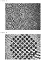
- the first bonding layer pattern was printed so as to have an aggregate shape, and a second bonding layer pattern, which is each pattern constituting the first bonding layer pattern, had a circular shape having a diameter of 35 ⁇ m, and the second bonding layer pattern had an aperture ratio of 8%. Further, the first bonding layer pattern had a total aperture ratio of 68%.
- FIG. 1 is a view illustrating a cliché for gravure printing, which is used when a pattern is formed by a gravure printing process in Example 1.
- FIG. 8 is a view illustrating a pattern formed by a gravure printing process in Example 1.
- FIG. 9 is a view illustrating a second bonding layer pattern which is any one of the patterns constituting the first bonding layer pattern of FIG. 8 .
- a bonding layer pattern was formed on one surface of a polyethylene separator by using the bonding layer solution prepared in Example 1, a coin cell was assembled to test the performance of the separator, and a coin cell resistance value of the separator was measured.
- the separator was first disposed inside a case in the form of a coin, and a coin cell was assembled in the order of a positive electrode, a separator, a spacer, a wave spring, a gasket, and a cover (negative electrode) from the lower portion thereof. Thereafter, the coin cell resistance value of the separator was measured by injecting an electrolytic solution thereinto.
- the coin cell resistance value was measured by using an electrochemical analyzer measurement apparatus manufactured by Solatron Co., Ltd.
- a bonding layer pattern was formed on both surfaces of a polyethylene separator by using the bonding layer solution prepared in Example 1, and a coin cell resistance value of the separator was measured.
- a first bonding layer pattern having an aperture ratio of 68% in a form of aggregate was formed on one surface of a polyethylene separator by using a gravure printing method, and a bonding strength between the first bonding layer pattern and the separator was measured.
- the bonding strength was measured by applying heat to the printed separator at 100°C at a rate of 1 m/min while allowing printing surfaces to face each other to stack the printed separators at a width of 25 mm, and performing a 180° peel test method.
- the patterns formed by the gravure printing process in Example 4 were regularly disposed at a gap of 500 ⁇ m.
- FIG. 1 is a view illustrating a cliché for gravure printing, which is used when a pattern is formed by a gravure printing process in Example 4.
- a bonding layer pattern was formed on both surfaces of a polyethylene separator by a gravure printing method using the bonding layer solution prepared in Example 1, and the wetting time according to the wetting of the electrolytic solution was recorded.
- a first bonding layer pattern was formed by using a cliché having no partition wall.
- FIG. 2 is a view illustrating a cliché for gravure printing, which is used when a pattern is formed by a gravure printing process in Comparative Example 1.
- the bonding layer solution prepared in Example 1 was used and fully coated on one surface of a polyethylene separator, and then a coin cell resistance value of the separator was measured.
- the bonding layer solution prepared in Example 1 was used and fully coated on both surfaces of a polyethylene separator, and then a coin cell resistance value of the separator was measured.
- a first bonding layer pattern having an aperture ratio of 80% in a form of aggregate was formed on one surface of a polyethylene separator by using a gravure printing method, and a bonding strength between the first bonding layer pattern and the separator was measured.
- the bonding strength was measured by applying heat to the printed separator at 100°C at a rate of 1 m/min while allowing printing surfaces to face each other to stack the printed separators at a width of 25 mm, and performing a 180° peel test method.
- FIG. 4 is a view illustrating a cliché for gravure printing, which is used when a pattern is formed by a gravure printing process in Comparative Example 4.
- FIG. 6 is a view illustrating a pattern formed by a gravure printing process in Comparative Example 4.
- a bonding strength between a bonding layer and a separator was measured without forming the bonding layer.
- the bonding strengths of the separators according to Example 4 and Comparative Examples 4 and 5 are shown in Table 1.
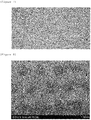
- FIG. 7 is a view illustrating the separator in which the bonding layer is not formed in Comparative Example 5.
- the bonding layer solution prepared in Example 1 was fully coated on both surfaces of a polyethylene separator by bar coating, and the wetting time according to the wetting of the electrolytic solution was recorded.
- the wetting was performed by the following method.
- the separators according to Example 5 (a pattern was formed on both surfaces of a separator) and Comparative Example 6 (a bonding layer solution was fully coated on both surfaces of a separator) were cut into 2 cm x 2 cm, and then the both surfaces of the separators were brought into contact with a polyethylene phthalate (PET) films having the same size, and laminated to the PET films while applying heat at 100°C at a rate of 1 m/min. And then, the separators were covered with an imide tape, and then wetted by pouring an electrolytic solution thereto. As the electrolytic solution, a propylene carbonate solvent was used. And then, after the wetting, the time taken until the entire surface was wetted was measured by using a stopwatch.
- PET polyethylene phthalate
- the wetting time of the separator with both surfaces patterned by a gravure printing process was shorter than that of the separator which was fully coated.
- the shorter wetting time means that the electrode and the separator inside the battery are smoothly wetted, and it is possible to improve the efficiency of performing the process by shortening the wetting time.
- the wetting speed is an element which is important for the battery performance when an electrolytic solution is injected into a battery in an assembly process of the battery. If the wetting of the separator is not performed well, and thus the wetting time is elongated, ions are not easily transferred, and as a result, a resistance acts against the battery.
- Bonding Strength (gf/25 mm)
- Example 4 (separator with a first bonding layer pattern having an aperture ratio of 68% and formed on one surface thereof) 21.19 Comparative Example 4 (separator with a first bonding layer pattern having an aperture ration of 80% and formed on one surface thereof) 7.32 Comparative Example 5 (separator which is not subjected to a printing process) 0
- the bonding strengths between the first bonding layer pattern and the separator are different from each other according to the aperture ratio of the pattern, and the smaller the aperture ratio of the pattern is, the greater the bonding strength of the separator is. Accordingly, the bonding strength can be adjusted according to the aperture ratio of the bonding layer pattern.
- the wetting time of the electrolytic solution for the separators according to Example 1 and Comparative Example 1 was measured. More specifically, the wetting time of the electrolytic solution for the separator according to Example 1 was 1 minute and 54 seconds, and the wetting time of the electrolytic solution for the separator according to Comparative Example 1 was 4 minutes and 12 seconds.
- the electrolytic solution wetting phenomenon for the separators in Example 1 and Comparative Example 1 is illustrated in the following FIG. 15 .
- a separator according to an exemplary embodiment of the present application may allow a bonding layer pattern to be easily printed by using a low viscous bonding composition which does not include an additive such as a thickener.
- the separator according to an exemplary embodiment of the present application has a characteristic in which a resistance acting inside a secondary battery is lower and a wetting time of an electrolytic solution is faster than when a bonding layer of the separator is formed by a full surface coating method, thereby having an effect in which excellent performance of the secondary battery may be implemented.
Landscapes
- Chemical & Material Sciences (AREA)
- Chemical Kinetics & Catalysis (AREA)
- Electrochemistry (AREA)
- General Chemical & Material Sciences (AREA)
- Engineering & Computer Science (AREA)
- Manufacturing & Machinery (AREA)
- Materials Engineering (AREA)
- Cell Separators (AREA)
Claims (6)
- Séparateur comprenant :un substrat poreux ; etun premier motif de couche de liaison prévu sur au moins une surface du substrat poreux,dans lequel chaque motif constituant le premier motif de couche de liaison est constitué d'un second motif de couche de liaison sous la forme d'un agrégat ayant un rapport d'ouverture de 5 % ou plus et 40 % ou moins, etle premier motif de couche de liaison a un rapport d'ouverture total de 20 % ou plus et de moins de 80 %.
- Séparateur selon la revendication 1, dans lequel une forme de chaque motif constituant le second motif de couche de liaison comprend au moins l'un d'un cercle, d'une ellipse, et d'un polygone.
- Séparateur selon la revendication 1, dans lequel chaque motif constituant le second motif de couche de liaison a un diamètre de 10 µm à 100 µm.
- Séparateur selon la revendication 1, dans lequel un espace entre des motifs constituant le premier motif de couche de liaison est de 100 µm à 1 000 µm.
- Séparateur selon la revendication 1, dans lequel le séparateur a une résistance de 0,65 ohm ou moins.
- Batterie comprenant le séparateur selon l'une quelconque des revendications 1 à 5.
Applications Claiming Priority (2)
| Application Number | Priority Date | Filing Date | Title |
|---|---|---|---|
| KR20150182167 | 2015-12-18 | ||
| PCT/KR2016/014882 WO2017105156A1 (fr) | 2015-12-18 | 2016-12-19 | Séparateur et batterie le comprenant |
Publications (3)
| Publication Number | Publication Date |
|---|---|
| EP3376563A1 EP3376563A1 (fr) | 2018-09-19 |
| EP3376563A4 EP3376563A4 (fr) | 2019-01-16 |
| EP3376563B1 true EP3376563B1 (fr) | 2020-09-23 |
Family
ID=59056905
Family Applications (1)
| Application Number | Title | Priority Date | Filing Date |
|---|---|---|---|
| EP16876098.1A Active EP3376563B1 (fr) | 2015-12-18 | 2016-12-19 | Séparateur et batterie le comprenant |
Country Status (6)
| Country | Link |
|---|---|
| US (1) | US10804559B2 (fr) |
| EP (1) | EP3376563B1 (fr) |
| JP (1) | JP6734387B2 (fr) |
| KR (1) | KR102050627B1 (fr) |
| CN (1) | CN108431992B (fr) |
| WO (1) | WO2017105156A1 (fr) |
Families Citing this family (9)
| Publication number | Priority date | Publication date | Assignee | Title |
|---|---|---|---|---|
| KR102354261B1 (ko) * | 2018-06-12 | 2022-01-20 | 주식회사 엘지화학 | 패턴화 전극접착층이 구비된 전기화학소자용 분리막 및 상기 분리막의 제조방법 |
| KR102948562B1 (ko) * | 2019-05-10 | 2026-04-06 | 현대자동차주식회사 | 전고체 전지용 바인더 용액, 이를 포함하는 전고체 전지용 전극 슬러리 및 이를 이용한 전고체 전지의 제조방법 |
| CN111129406A (zh) * | 2019-12-31 | 2020-05-08 | 湖北亿纬动力有限公司 | 一种水系高粘性涂胶隔膜、其制备方法和在电池中的应用 |
| CN111312967B (zh) * | 2020-02-27 | 2022-06-07 | 河北金力新能源科技股份有限公司 | 一种陶瓷涂覆浆料及其制备方法、锂电池隔膜、锂电池 |
| CA3217308A1 (fr) | 2021-09-07 | 2023-03-16 | Yoshitaka Nakagawa | Separateur pour dispositif de stockage d'energie |
| EP4553986A4 (fr) | 2022-07-08 | 2025-06-11 | Asahi Kasei Battery Separator Corporation | Séparateur pour dispositif de stockage d'énergie |
| KR102930894B1 (ko) * | 2022-11-18 | 2026-02-24 | 주식회사 엘지화학 | 리튬 이차 전지 |
| JP7696382B2 (ja) * | 2023-03-01 | 2025-06-20 | プライムプラネットエナジー&ソリューションズ株式会社 | 蓄電デバイスの製造方法 |
| JP2024123561A (ja) * | 2023-03-01 | 2024-09-12 | プライムプラネットエナジー&ソリューションズ株式会社 | 蓄電デバイスの製造方法 |
Family Cites Families (13)
| Publication number | Priority date | Publication date | Assignee | Title |
|---|---|---|---|---|
| KR100363270B1 (ko) * | 1999-12-20 | 2002-11-30 | 주식회사 코캄엔지니어링 | 리튬 2차 전지용 전극 조립체 및 리튬 2차 전지용 전극 조립체를 제조하기 위한 방법 및 장치 |
| KR101801049B1 (ko) | 2010-08-31 | 2017-11-24 | 제온 코포레이션 | 전지 다공막용 슬러리 조성물, 이차 전지용 다공막의 제조 방법, 이차 전지용 다공막, 이차 전지용 전극, 이차 전지용 세퍼레이터 및 이차 전지 |
| AU2010360916B2 (en) | 2010-09-17 | 2016-05-19 | Creative Co., Ltd. | Solid fuel |
| KR101281037B1 (ko) * | 2011-04-06 | 2013-07-09 | 주식회사 엘지화학 | 세퍼레이터 및 이를 구비하는 전기화학소자 |
| US9276247B2 (en) | 2011-04-06 | 2016-03-01 | Lg Chem, Ltd. | Separator and electrochemical device comprising the same |
| KR101491061B1 (ko) * | 2012-05-03 | 2015-02-10 | 주식회사 엘지화학 | 전극 조립체 및 그의 제조방법 |
| US8921841B2 (en) * | 2012-05-09 | 2014-12-30 | Samsung Corning Precision Materials Co., Ltd. | Porous glass substrate for displays and method of manufacturing the same |
| CN103450444B (zh) | 2013-08-22 | 2015-09-02 | 江苏科技大学 | 一种氟硅双重改性水性聚氨酯乳液及其制备方法 |
| KR20150048082A (ko) * | 2013-10-25 | 2015-05-06 | 주식회사 엘지화학 | 분리막에 점착성 바인더를 도포하는 방법 |
| JP6296260B2 (ja) | 2013-11-04 | 2018-03-20 | エルジー・ケム・リミテッド | 二次電池用接着層の形成方法 |
| KR20150057480A (ko) * | 2013-11-19 | 2015-05-28 | 삼성에스디아이 주식회사 | 세퍼레이터, 이를 포함하는 리튬 전지, 상기 세퍼레이터의 제조방법, 및 상기 리튬 전지의 제조방법 |
| KR20150057481A (ko) * | 2013-11-19 | 2015-05-28 | 삼성에스디아이 주식회사 | 리튬 전지용 세퍼레이터, 이를 포함하는 리튬 전지, 및 상기 리튬 전지의 제조방법 |
| JP2015141838A (ja) * | 2014-01-29 | 2015-08-03 | 旭化成イーマテリアルズ株式会社 | 蓄電デバイス用セパレータ、蓄電デバイス、リチウムイオン二次電池及び共重合体 |
-
2016
- 2016-12-19 CN CN201680073097.6A patent/CN108431992B/zh active Active
- 2016-12-19 EP EP16876098.1A patent/EP3376563B1/fr active Active
- 2016-12-19 US US15/779,275 patent/US10804559B2/en active Active
- 2016-12-19 WO PCT/KR2016/014882 patent/WO2017105156A1/fr not_active Ceased
- 2016-12-19 KR KR1020160173728A patent/KR102050627B1/ko active Active
- 2016-12-19 JP JP2018545796A patent/JP6734387B2/ja active Active
Non-Patent Citations (1)
| Title |
|---|
| None * |
Also Published As
| Publication number | Publication date |
|---|---|
| CN108431992B (zh) | 2021-07-16 |
| KR102050627B1 (ko) | 2019-12-02 |
| KR20170073539A (ko) | 2017-06-28 |
| JP6734387B2 (ja) | 2020-08-05 |
| US10804559B2 (en) | 2020-10-13 |
| EP3376563A1 (fr) | 2018-09-19 |
| CN108431992A (zh) | 2018-08-21 |
| EP3376563A4 (fr) | 2019-01-16 |
| US20180351194A1 (en) | 2018-12-06 |
| WO2017105156A1 (fr) | 2017-06-22 |
| JP2018535534A (ja) | 2018-11-29 |
Similar Documents
| Publication | Publication Date | Title |
|---|---|---|
| EP3376563B1 (fr) | Séparateur et batterie le comprenant | |
| KR101485387B1 (ko) | 전기 화학 소자용 세퍼레이터 및 그것을 사용한 전기 화학 소자, 및 그 전기 화학 소자용 세퍼레이터의 제조 방법 | |
| Liu et al. | Effect of Al2O3/SiO2 composite ceramic layers on performance of polypropylene separator for lithium-ion batteries | |
| EP2983228B1 (fr) | Dispositif de stockage d'énergie électrochimique | |
| CN103956448B (zh) | 隔离膜及锂离子二次电池 | |
| KR100736512B1 (ko) | 리튬이온 2차전지 | |
| CN104838518A (zh) | 电池隔板上的陶瓷涂层 | |
| US11133560B2 (en) | Insulating tape and li-ion battery adopting the same | |
| JP5818078B2 (ja) | 非水電解質二次電池の製造方法 | |
| KR20140071951A (ko) | 내열성 다공질막, 비수전지용 세퍼레이터 및 비수전지 | |
| CN107437623B (zh) | 锂离子电池正极片及其制备方法 | |
| EP3033783A1 (fr) | Batterie au lithium comprenant un électrolyte solide microstructuré | |
| JP2013105680A (ja) | 二次電池 | |
| CN105921343A (zh) | 单体大容量锂离子电池制造方法和极片涂布设备 | |
| CN101278421B (zh) | 非水电解质电池用正极、非水电解质电池用负极、非水电解质电池用隔离件以及使用它们的非水电解质电池 | |
| JP2023093114A (ja) | セパレータ及びこれを備える非水電解液二次電池並びに組電池 | |
| CN102637848B (zh) | 一种锂离子电池极片的制备方法 | |
| JPWO2011114473A1 (ja) | 電池用電極の製造方法 | |
| CN104979562A (zh) | 一种过放电能至0v的锂离子电池复合正极及其制备方法和应用 | |
| JP5017995B2 (ja) | リチウム二次電池用極板の製造方法、その製造法を用いたリチウム二次電池用極板とリチウム二次電池 | |
| JP5888079B2 (ja) | セパレータ、及びそれを用いた非水系二次電池 | |
| CN114944467B (zh) | 一种极片及包括该极片的电池 | |
| CN101882693A (zh) | 锂离子二次电池及其负极片的制备方法 | |
| JP2017098065A (ja) | 二次電池用電極、及びそれを用いた二次電池 | |
| JP2016219302A (ja) | 二次電池用の電極およびその製造方法 |
Legal Events
| Date | Code | Title | Description |
|---|---|---|---|
| STAA | Information on the status of an ep patent application or granted ep patent |
Free format text: STATUS: THE INTERNATIONAL PUBLICATION HAS BEEN MADE |
|
| PUAI | Public reference made under article 153(3) epc to a published international application that has entered the european phase |
Free format text: ORIGINAL CODE: 0009012 |
|
| STAA | Information on the status of an ep patent application or granted ep patent |
Free format text: STATUS: REQUEST FOR EXAMINATION WAS MADE |
|
| 17P | Request for examination filed |
Effective date: 20180612 |
|
| AK | Designated contracting states |
Kind code of ref document: A1 Designated state(s): AL AT BE BG CH CY CZ DE DK EE ES FI FR GB GR HR HU IE IS IT LI LT LU LV MC MK MT NL NO PL PT RO RS SE SI SK SM TR |
|
| AX | Request for extension of the european patent |
Extension state: BA ME |
|
| A4 | Supplementary search report drawn up and despatched |
Effective date: 20181219 |
|
| RIC1 | Information provided on ipc code assigned before grant |
Ipc: H01M 2/14 20060101ALI20181213BHEP Ipc: H01M 2/16 20060101AFI20181213BHEP Ipc: H01M 10/0525 20100101ALI20181213BHEP |
|
| DAV | Request for validation of the european patent (deleted) | ||
| DAX | Request for extension of the european patent (deleted) | ||
| GRAP | Despatch of communication of intention to grant a patent |
Free format text: ORIGINAL CODE: EPIDOSNIGR1 |
|
| STAA | Information on the status of an ep patent application or granted ep patent |
Free format text: STATUS: GRANT OF PATENT IS INTENDED |
|
| INTG | Intention to grant announced |
Effective date: 20191128 |
|
| GRAS | Grant fee paid |
Free format text: ORIGINAL CODE: EPIDOSNIGR3 |
|
| GRAA | (expected) grant |
Free format text: ORIGINAL CODE: 0009210 |
|
| STAA | Information on the status of an ep patent application or granted ep patent |
Free format text: STATUS: THE PATENT HAS BEEN GRANTED |
|
| AK | Designated contracting states |
Kind code of ref document: B1 Designated state(s): AL AT BE BG CH CY CZ DE DK EE ES FI FR GB GR HR HU IE IS IT LI LT LU LV MC MK MT NL NO PL PT RO RS SE SI SK SM TR |
|
| REG | Reference to a national code |
Ref country code: GB Ref legal event code: FG4D |
|
| REG | Reference to a national code |
Ref country code: CH Ref legal event code: EP |
|
| REG | Reference to a national code |
Ref country code: IE Ref legal event code: FG4D |
|
| REG | Reference to a national code |
Ref country code: AT Ref legal event code: REF Ref document number: 1317292 Country of ref document: AT Kind code of ref document: T Effective date: 20201015 Ref country code: DE Ref legal event code: R096 Ref document number: 602016044747 Country of ref document: DE |
|
| REG | Reference to a national code |
Ref country code: DE Ref legal event code: R079 Ref document number: 602016044747 Country of ref document: DE Free format text: PREVIOUS MAIN CLASS: H01M0002160000 Ipc: H01M0050409000 |
|
| PG25 | Lapsed in a contracting state [announced via postgrant information from national office to epo] |
Ref country code: FI Free format text: LAPSE BECAUSE OF FAILURE TO SUBMIT A TRANSLATION OF THE DESCRIPTION OR TO PAY THE FEE WITHIN THE PRESCRIBED TIME-LIMIT Effective date: 20200923 Ref country code: HR Free format text: LAPSE BECAUSE OF FAILURE TO SUBMIT A TRANSLATION OF THE DESCRIPTION OR TO PAY THE FEE WITHIN THE PRESCRIBED TIME-LIMIT Effective date: 20200923 Ref country code: SE Free format text: LAPSE BECAUSE OF FAILURE TO SUBMIT A TRANSLATION OF THE DESCRIPTION OR TO PAY THE FEE WITHIN THE PRESCRIBED TIME-LIMIT Effective date: 20200923 Ref country code: BG Free format text: LAPSE BECAUSE OF FAILURE TO SUBMIT A TRANSLATION OF THE DESCRIPTION OR TO PAY THE FEE WITHIN THE PRESCRIBED TIME-LIMIT Effective date: 20201223 Ref country code: GR Free format text: LAPSE BECAUSE OF FAILURE TO SUBMIT A TRANSLATION OF THE DESCRIPTION OR TO PAY THE FEE WITHIN THE PRESCRIBED TIME-LIMIT Effective date: 20201224 Ref country code: NO Free format text: LAPSE BECAUSE OF FAILURE TO SUBMIT A TRANSLATION OF THE DESCRIPTION OR TO PAY THE FEE WITHIN THE PRESCRIBED TIME-LIMIT Effective date: 20201223 |
|
| REG | Reference to a national code |
Ref country code: AT Ref legal event code: MK05 Ref document number: 1317292 Country of ref document: AT Kind code of ref document: T Effective date: 20200923 |
|
| PG25 | Lapsed in a contracting state [announced via postgrant information from national office to epo] |
Ref country code: RS Free format text: LAPSE BECAUSE OF FAILURE TO SUBMIT A TRANSLATION OF THE DESCRIPTION OR TO PAY THE FEE WITHIN THE PRESCRIBED TIME-LIMIT Effective date: 20200923 Ref country code: LV Free format text: LAPSE BECAUSE OF FAILURE TO SUBMIT A TRANSLATION OF THE DESCRIPTION OR TO PAY THE FEE WITHIN THE PRESCRIBED TIME-LIMIT Effective date: 20200923 |
|
| REG | Reference to a national code |
Ref country code: NL Ref legal event code: MP Effective date: 20200923 |
|
| REG | Reference to a national code |
Ref country code: LT Ref legal event code: MG4D |
|
| PG25 | Lapsed in a contracting state [announced via postgrant information from national office to epo] |
Ref country code: EE Free format text: LAPSE BECAUSE OF FAILURE TO SUBMIT A TRANSLATION OF THE DESCRIPTION OR TO PAY THE FEE WITHIN THE PRESCRIBED TIME-LIMIT Effective date: 20200923 Ref country code: SM Free format text: LAPSE BECAUSE OF FAILURE TO SUBMIT A TRANSLATION OF THE DESCRIPTION OR TO PAY THE FEE WITHIN THE PRESCRIBED TIME-LIMIT Effective date: 20200923 Ref country code: LT Free format text: LAPSE BECAUSE OF FAILURE TO SUBMIT A TRANSLATION OF THE DESCRIPTION OR TO PAY THE FEE WITHIN THE PRESCRIBED TIME-LIMIT Effective date: 20200923 Ref country code: PT Free format text: LAPSE BECAUSE OF FAILURE TO SUBMIT A TRANSLATION OF THE DESCRIPTION OR TO PAY THE FEE WITHIN THE PRESCRIBED TIME-LIMIT Effective date: 20210125 Ref country code: RO Free format text: LAPSE BECAUSE OF FAILURE TO SUBMIT A TRANSLATION OF THE DESCRIPTION OR TO PAY THE FEE WITHIN THE PRESCRIBED TIME-LIMIT Effective date: 20200923 Ref country code: CZ Free format text: LAPSE BECAUSE OF FAILURE TO SUBMIT A TRANSLATION OF THE DESCRIPTION OR TO PAY THE FEE WITHIN THE PRESCRIBED TIME-LIMIT Effective date: 20200923 |
|
| PG25 | Lapsed in a contracting state [announced via postgrant information from national office to epo] |
Ref country code: PL Free format text: LAPSE BECAUSE OF FAILURE TO SUBMIT A TRANSLATION OF THE DESCRIPTION OR TO PAY THE FEE WITHIN THE PRESCRIBED TIME-LIMIT Effective date: 20200923 Ref country code: IS Free format text: LAPSE BECAUSE OF FAILURE TO SUBMIT A TRANSLATION OF THE DESCRIPTION OR TO PAY THE FEE WITHIN THE PRESCRIBED TIME-LIMIT Effective date: 20210123 Ref country code: ES Free format text: LAPSE BECAUSE OF FAILURE TO SUBMIT A TRANSLATION OF THE DESCRIPTION OR TO PAY THE FEE WITHIN THE PRESCRIBED TIME-LIMIT Effective date: 20200923 Ref country code: AT Free format text: LAPSE BECAUSE OF FAILURE TO SUBMIT A TRANSLATION OF THE DESCRIPTION OR TO PAY THE FEE WITHIN THE PRESCRIBED TIME-LIMIT Effective date: 20200923 Ref country code: AL Free format text: LAPSE BECAUSE OF FAILURE TO SUBMIT A TRANSLATION OF THE DESCRIPTION OR TO PAY THE FEE WITHIN THE PRESCRIBED TIME-LIMIT Effective date: 20200923 |
|
| REG | Reference to a national code |
Ref country code: DE Ref legal event code: R097 Ref document number: 602016044747 Country of ref document: DE |
|
| PG25 | Lapsed in a contracting state [announced via postgrant information from national office to epo] |
Ref country code: SK Free format text: LAPSE BECAUSE OF FAILURE TO SUBMIT A TRANSLATION OF THE DESCRIPTION OR TO PAY THE FEE WITHIN THE PRESCRIBED TIME-LIMIT Effective date: 20200923 |
|
| PLBE | No opposition filed within time limit |
Free format text: ORIGINAL CODE: 0009261 |
|
| REG | Reference to a national code |
Ref country code: CH Ref legal event code: PL |
|
| STAA | Information on the status of an ep patent application or granted ep patent |
Free format text: STATUS: NO OPPOSITION FILED WITHIN TIME LIMIT |
|
| PG25 | Lapsed in a contracting state [announced via postgrant information from national office to epo] |
Ref country code: SI Free format text: LAPSE BECAUSE OF FAILURE TO SUBMIT A TRANSLATION OF THE DESCRIPTION OR TO PAY THE FEE WITHIN THE PRESCRIBED TIME-LIMIT Effective date: 20200923 Ref country code: DK Free format text: LAPSE BECAUSE OF FAILURE TO SUBMIT A TRANSLATION OF THE DESCRIPTION OR TO PAY THE FEE WITHIN THE PRESCRIBED TIME-LIMIT Effective date: 20200923 Ref country code: MC Free format text: LAPSE BECAUSE OF FAILURE TO SUBMIT A TRANSLATION OF THE DESCRIPTION OR TO PAY THE FEE WITHIN THE PRESCRIBED TIME-LIMIT Effective date: 20200923 |
|
| 26N | No opposition filed |
Effective date: 20210624 |
|
| REG | Reference to a national code |
Ref country code: BE Ref legal event code: MM Effective date: 20201231 |
|
| PG25 | Lapsed in a contracting state [announced via postgrant information from national office to epo] |
Ref country code: IE Free format text: LAPSE BECAUSE OF NON-PAYMENT OF DUE FEES Effective date: 20201219 Ref country code: LU Free format text: LAPSE BECAUSE OF NON-PAYMENT OF DUE FEES Effective date: 20201219 Ref country code: IT Free format text: LAPSE BECAUSE OF FAILURE TO SUBMIT A TRANSLATION OF THE DESCRIPTION OR TO PAY THE FEE WITHIN THE PRESCRIBED TIME-LIMIT Effective date: 20200923 |
|
| PG25 | Lapsed in a contracting state [announced via postgrant information from national office to epo] |
Ref country code: LI Free format text: LAPSE BECAUSE OF NON-PAYMENT OF DUE FEES Effective date: 20201231 Ref country code: CH Free format text: LAPSE BECAUSE OF NON-PAYMENT OF DUE FEES Effective date: 20201231 |
|
| PG25 | Lapsed in a contracting state [announced via postgrant information from national office to epo] |
Ref country code: TR Free format text: LAPSE BECAUSE OF FAILURE TO SUBMIT A TRANSLATION OF THE DESCRIPTION OR TO PAY THE FEE WITHIN THE PRESCRIBED TIME-LIMIT Effective date: 20200923 Ref country code: MT Free format text: LAPSE BECAUSE OF FAILURE TO SUBMIT A TRANSLATION OF THE DESCRIPTION OR TO PAY THE FEE WITHIN THE PRESCRIBED TIME-LIMIT Effective date: 20200923 Ref country code: CY Free format text: LAPSE BECAUSE OF FAILURE TO SUBMIT A TRANSLATION OF THE DESCRIPTION OR TO PAY THE FEE WITHIN THE PRESCRIBED TIME-LIMIT Effective date: 20200923 |
|
| PG25 | Lapsed in a contracting state [announced via postgrant information from national office to epo] |
Ref country code: MK Free format text: LAPSE BECAUSE OF FAILURE TO SUBMIT A TRANSLATION OF THE DESCRIPTION OR TO PAY THE FEE WITHIN THE PRESCRIBED TIME-LIMIT Effective date: 20200923 |
|
| PG25 | Lapsed in a contracting state [announced via postgrant information from national office to epo] |
Ref country code: BE Free format text: LAPSE BECAUSE OF NON-PAYMENT OF DUE FEES Effective date: 20201231 |
|
| REG | Reference to a national code |
Ref country code: DE Ref legal event code: R081 Ref document number: 602016044747 Country of ref document: DE Owner name: LG ENERGY SOLUTION, LTD., KR Free format text: FORMER OWNER: LG CHEM. LTD., SEOUL/SOUL, KR |
|
| P01 | Opt-out of the competence of the unified patent court (upc) registered |
Effective date: 20230512 |
|
| PG25 | Lapsed in a contracting state [announced via postgrant information from national office to epo] |
Ref country code: NL Free format text: LAPSE BECAUSE OF NON-PAYMENT OF DUE FEES Effective date: 20200923 |
|
| REG | Reference to a national code |
Ref country code: GB Ref legal event code: 732E Free format text: REGISTERED BETWEEN 20230824 AND 20230831 |
|
| PGFP | Annual fee paid to national office [announced via postgrant information from national office to epo] |
Ref country code: DE Payment date: 20251120 Year of fee payment: 10 |
|
| PGFP | Annual fee paid to national office [announced via postgrant information from national office to epo] |
Ref country code: GB Payment date: 20251120 Year of fee payment: 10 |
|
| PGFP | Annual fee paid to national office [announced via postgrant information from national office to epo] |
Ref country code: FR Payment date: 20251125 Year of fee payment: 10 |