EP3377238B1 - Procédé de coulée de bande de métal à réglage de bombage - Google Patents
Procédé de coulée de bande de métal à réglage de bombage Download PDFInfo
- Publication number
- EP3377238B1 EP3377238B1 EP15908989.5A EP15908989A EP3377238B1 EP 3377238 B1 EP3377238 B1 EP 3377238B1 EP 15908989 A EP15908989 A EP 15908989A EP 3377238 B1 EP3377238 B1 EP 3377238B1
- Authority
- EP
- European Patent Office
- Prior art keywords
- casting
- expansion
- cast strip
- expansion ring
- roll
- Prior art date
- Legal status (The legal status is an assumption and is not a legal conclusion. Google has not performed a legal analysis and makes no representation as to the accuracy of the status listed.)
- Active
Links
Images





Classifications
-
- B—PERFORMING OPERATIONS; TRANSPORTING
- B22—CASTING; POWDER METALLURGY
- B22D—CASTING OF METALS; CASTING OF OTHER SUBSTANCES BY THE SAME PROCESSES OR DEVICES
- B22D11/00—Continuous casting of metals, i.e. casting in indefinite lengths
- B22D11/16—Controlling or regulating processes or operations
- B22D11/168—Controlling or regulating processes or operations for adjusting the mould size or mould taper
-
- B—PERFORMING OPERATIONS; TRANSPORTING
- B22—CASTING; POWDER METALLURGY
- B22D—CASTING OF METALS; CASTING OF OTHER SUBSTANCES BY THE SAME PROCESSES OR DEVICES
- B22D11/00—Continuous casting of metals, i.e. casting in indefinite lengths
- B22D11/06—Continuous casting of metals, i.e. casting in indefinite lengths into moulds with travelling walls, e.g. with rolls, plates, belts, caterpillars
- B22D11/0622—Continuous casting of metals, i.e. casting in indefinite lengths into moulds with travelling walls, e.g. with rolls, plates, belts, caterpillars formed by two casting wheels
-
- B—PERFORMING OPERATIONS; TRANSPORTING
- B22—CASTING; POWDER METALLURGY
- B22D—CASTING OF METALS; CASTING OF OTHER SUBSTANCES BY THE SAME PROCESSES OR DEVICES
- B22D11/00—Continuous casting of metals, i.e. casting in indefinite lengths
- B22D11/06—Continuous casting of metals, i.e. casting in indefinite lengths into moulds with travelling walls, e.g. with rolls, plates, belts, caterpillars
- B22D11/0637—Accessories therefor
-
- B—PERFORMING OPERATIONS; TRANSPORTING
- B22—CASTING; POWDER METALLURGY
- B22D—CASTING OF METALS; CASTING OF OTHER SUBSTANCES BY THE SAME PROCESSES OR DEVICES
- B22D11/00—Continuous casting of metals, i.e. casting in indefinite lengths
- B22D11/06—Continuous casting of metals, i.e. casting in indefinite lengths into moulds with travelling walls, e.g. with rolls, plates, belts, caterpillars
- B22D11/0637—Accessories therefor
- B22D11/064—Accessories therefor for supplying molten metal
-
- B—PERFORMING OPERATIONS; TRANSPORTING
- B22—CASTING; POWDER METALLURGY
- B22D—CASTING OF METALS; CASTING OF OTHER SUBSTANCES BY THE SAME PROCESSES OR DEVICES
- B22D11/00—Continuous casting of metals, i.e. casting in indefinite lengths
- B22D11/06—Continuous casting of metals, i.e. casting in indefinite lengths into moulds with travelling walls, e.g. with rolls, plates, belts, caterpillars
- B22D11/0637—Accessories therefor
- B22D11/0648—Casting surfaces
- B22D11/0651—Casting wheels
-
- B—PERFORMING OPERATIONS; TRANSPORTING
- B22—CASTING; POWDER METALLURGY
- B22D—CASTING OF METALS; CASTING OF OTHER SUBSTANCES BY THE SAME PROCESSES OR DEVICES
- B22D11/00—Continuous casting of metals, i.e. casting in indefinite lengths
- B22D11/06—Continuous casting of metals, i.e. casting in indefinite lengths into moulds with travelling walls, e.g. with rolls, plates, belts, caterpillars
- B22D11/0637—Accessories therefor
- B22D11/0665—Accessories therefor for treating the casting surfaces, e.g. calibrating, cleaning, dressing, preheating
- B22D11/0668—Accessories therefor for treating the casting surfaces, e.g. calibrating, cleaning, dressing, preheating for dressing, coating or lubricating
Definitions
- This invention relates to the casting of metal strip by continuous casting in a twin roll caster.
- molten metal is introduced between a pair of counter-rotated horizontal casting rolls that are cooled so that metal shells solidify on the moving casting roll surfaces and are brought together at a nip between them to produce a solidified strip product delivered downwardly from the nip between the casting rolls.
- the term "nip" is used herein to refer to the general region at which the casting rolls are closest together.
- the molten metal may be poured from a ladle into a smaller vessel or series of smaller vessels from which it flows through a metal delivery nozzle and nozzles located above the nip forming a casting pool of molten metal supported on the casting surfaces of the casting rolls immediately above the nip and extending along the length of the nip. This casting pool is usually confined between side plates or dams held in sliding engagement with end surfaces of the casting rolls so as to restrict the two ends of the casting pool against outflow.
- the twin roll caster is capable of continuously producing cast strip from molten steel through a sequence of ladles positioned on a turret.
- the molten metal is poured from each ladle in turn into a tundish and then into a moveable tundish before flowing through the metal delivery nozzle into the casting pool.
- the tundish enables the exchange of an empty ladle for a full ladle on the turret without disrupting the production of the cast strip.
- the casting rolls In casting thin strip by a twin roll caster, the casting rolls generally made of copper or copper alloy, usually coated with chromium or nickel, are cooled internally with cooling water enabling high heat fluxes and in turn rapid solidification of strip during casting, where the casting rolls undergo substantial thermal deformation from exposure to the molten metal.
- the crown of the casting surfaces of the casting rolls varies during a casting campaign.
- the crown of the casting surfaces of the casting rolls determines the strip thickness profile, i.e., cross-sectional shape, of the thin cast strip produced by the twin roll caster.
- Casting rolls with convex (i.e., positive crown) casting surfaces produce cast strip with a negative (i.e. center thermal fatigue from the cyclic heat flux experienced during twin roll casting on larger cylinder masses), and are much less responsive due to their large thermal mass.
- US 5560421 which is considered to represent the closest prior art, discloses a method of continuously casting thin strip in which a thin portion is formed close to an outer circumferential portion of each opposite end portion of a pair of water cooling drums, and a thin annular member having a hot water flow passage therein is formed in between the thin portion and a shaft, each thin annular member being expanded when hot water is supplied to the hot water flow passages so as to deform the thin ends of the water cooling drums.
- the amount of power applied to the expansion rings may be varied based on the feedback from the at least one sensor, said sensor or sensors capable of sensing at least one of the following properties:
- the insulating coating on each expansion ring is sufficiently thick to control or eliminate heat transfer from the expansion rings to the casting rolls.
- the insulating coating of at least 0.25mm (0.010) inch in thickness according to the invention (in one embodiment 0.63mm (0.025 inch)) is necessary to have an effective control of heat transfer from the expansion ring to the casting roll.
- the insulating coating on each expansion ring may be plasma sprayed on the expansion rings.
- the insulating coating may be plasma sprayed with zirconia spray such as 8% Yttria stabilized zirconia spray. Note that the insulating coating may additionally be applied to the cylindrical tube, but for economy and effectiveness the insulating coating should be applied to the expansion rings directly.
- each expansion ring may be made of stainless steel, nickel or nickel alloy.
- the heating element or elements may be located as desired in each expansion ring.
- Each expansion ring may provide a heating input of up to 30 kW; preferably, of at least 3 kW.
- Water flowing through the expansion rings may be regulated to expand or contract the expansion rings in radial dimension and, in turn, to increase or decrease the diameter of the cylindrical tube as desired to control the crown shape of the casting surfaces of the casting rolls during a campaign.
- the method of continuously casting thin strip by controlling roll crown may further comprise the step of controlling casting roll drive to vary the speed of rotation of the casting rolls while varying the radial dimension of the expansion rings responsive to at least one of the digital or analogous signals received from the at least one sensor and control roll crown of the casting surfaces of the casting rolls during the casting campaign.
- the method of continuously casting thin strip by controlling roll crown may comprise the step of positioning at least up to 15 expansion rings.
- the method of continuously casting thin strip by controlling roll crown may include the step of controlling casting roll drive to vary the speed of rotation of the casting rolls, while varying the radial dimension of the expansion rings with insulating coating spaced from the edge portions of the cast strip and the radial dimension of the expansion ring or rings with insulating coating corresponding to center portions of the cast strip responsive to electrical signals received from a sensor to control the roll crown of the casting surfaces of the casting rolls during the casting campaign.
- the expansion rings may be made of an austenitic stainless steel such as 18/8 austenitic stainless steel.
- Each expansion ring may have an annular dimension between 50 to 150 millimeters; preferably, 70 millimeters.
- Each expansion ring may have a width of up to 200 millimeters; preferably up to 100 mm, more preferably 83.5 millimeters.
- the crown of the casting surfaces of the casting rolls can readily be varied to achieve a desired thickness profile of the cast strip.
- Each expansion ring with an insulating coating thereon is adapted to increase or decrease in radial dimension and cause the cylindrical tube to expand changing crown of the casting surfaces of the casting rolls and the thickness profile of the cast strip.
- the thickness of the cylindrical tube may range between 40 and 80 millimeters in thickness or between 60 and 80 millimeters in thickness.
- At least one sensor may be positioned downstream adapted to sense the thickness profile of the cast strip and generate electrical signals indicative of the thickness profile of the cast strip.
- the sensor may be located adjacent to pinch rolls through which the strip passes after casting. Crown control of the casting surfaces of the casting rolls may be achieved by controlling the radial dimension of each expansion ring responsive to electrical signals received from said sensor. Furthermore, crown control of the casting surfaces of the casting rolls may be achieved by controlling the casting roll drive to vary the speed of rotation of the casting rolls while also varying the radial dimension of each expansion ring responsive to the electrical signals received from the sensor.
- each expansion ring may be controlled independently from the radial dimension of the other expansion ring or rings.
- the radial dimension of the expansion rings adjacent the strip edges on the casting surfaces of the casting rolls may be controlled independently from each other. Additionally, the radial dimension of the expansion rings adjacent the strip edges on the casting surfaces of the casting rolls may be controlled independently from the expansion ring or rings corresponding to the center portions of the cast strip.
- the present invention further provides an apparatus for continuously casting thin strip for controlling roll crown according to claim 9.
- the at least one sensor may be located adjacent to pinch rolls through which the strip passes after casting.
- the at least one sensor is preferably positioned downstream of the nip capable of sensing the thickness profile of the cast strip and generating electrical signals indicative of the thickness profile of the cast strip to control radial dimension of the expansion rings responsive to the electrical signals received from the sensor to control the roll crown of the casting surfaces of the casting rolls during the casting campaign.
- the apparatus for continuously casting thin strip by controlling roll crown may comprise a control system capable of controlling casting roll drive and varying the speed of rotation of the casting rolls, while varying the radial dimension of the expansion rings with an insulating coating thereon responsive to electrical signals received from the sensor to control the roll crown of the casting surfaces of the casting rolls during the casting campaign.
- the apparatus for continuously casting thin strip for controlling roll crown may further comprise a control system capable of controlling casting roll drive and varying the speed of rotation of the casting rolls, while varying the radial dimension of the expansion rings spaced from the edge portions of the cast strip and the radial dimension of the expansion ring or rings corresponding to center portions of the cast strip responsive to electrical signals received from the at least one sensor and control the roll crown of the casting surfaces of the casting rolls during the casting campaign.
- the expansion rings may be made of an austenitic stainless steel such as 18/8 austenitic stainless steel.
- Each expansion ring may have an annular dimension between 50 to 150 millimeters; (e.g., 70 millimeters).
- Each expansion ring may have a width of up to 200 millimeters; (e.g., 83.5 millimeters).
- each expansion ring with an insulating coating thereon is adapted to increase in radial dimension causing the cylindrical tube to expand and change crown of the casting surfaces of the casting rolls and the thickness profile of the cast strip during casting.
- Each expansion ring has at least one heating element that may be made of stainless steel, nickel or nickel alloy. The heating element or elements may be located around each expansion ring as desired.
- Each expansion ring may provide a heating input of up to 30 kW; preferably, of at least 3 kW.
- Crown control of the casting surfaces of the casting rolls may be achieved by controlling the radial dimension of each expansion ring responsive to the electrical signals received from a sensor. Furthermore, crown control of the casting surfaces of the casting rolls may be achieved by controlling the casting roll drive to vary the speed of rotation of the casting rolls, while also varying the radial dimension of each expansion ring with an insulating coating thereon responsive to the electrical signals received from the sensor.
- the radial dimension of the expansion rings adjacent the strip edges formed on the casting surfaces of the casting rolls may be controlled independently from each other. Additionally, the radial dimension of the expansion rings adjacent the strip edges formed on the casting surfaces of the casting rolls may be controlled independently from the expansion ring or rings corresponding to the center portions of the cast strip.
- the insulating coating of the expansion rings is sufficiently thick that the expansion ring can be heated to expand the expansion rings and control the crown shape of the casting rolls as desired during the casting campaign with a small amount of heat being conducted to the cylindrical tubing.
- An insulating coating of at least 0.25mm (0.010 inch) in thickness (e.g. 0.63mm (0.025 inch)) is effective. Note that the insulating coating may additionally be applied to the cylindrical tube, but for economy and effectiveness the insulating coating should be applied to the expansion rings directly during assembly for the expansion rings and casting rolls.
- the expansion rings may also have water passages there through to permit the flow of water through the passages in the rings, and regulate the water flow through those passages.
- the water flowing through the expansion rings may be regulated to expand or contract the expansion rings in radial dimension and, in turn, to increase or decrease the diameter of the cylindrical tube as desired to control the crown shape of the casting surfaces of the casting rolls during a campaign.
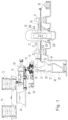
- a twin roll caster is illustrated that comprises a main machine frame 10 that stands up from the factory floor and supports a pair of counter-rotatable casting rolls 12 mounted in a module in a roll cassette 11.
- the casting rolls 12 are mounted in the roll cassette 11 for ease of operation and movement as described below.
- the roll cassette 11 facilitates rapid movement of the casting rolls 12 ready for casting from a setup position into an operative casting position as a unit in the caster, and ready removal of the casting rolls 12 from the casting position when the casting rolls 12 are to be replaced.
- the casting apparatus for continuously casting thin steel strip includes the pair of counter-rotatable casting rolls 12 having casting surfaces 12A laterally positioned to form a nip 18 there between.
- Molten metal is supplied from a ladle 13 through a metal delivery system to a metal delivery nozzle 17 (core nozzle) positioned between the casting rolls 12 above the nip 18.
- Molten metal thus delivered forms a casting pool 19 of molten metal above the nip 18 supported on the casting surfaces 12A of the casting rolls 12.
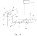
- This casting pool 19 is confined in the casting area at the ends of the casting rolls 12 by a pair of side closure plates, or side dams 20 (shown in dotted line in FIG. 2A ).
- the upper surface of the casting pool 19 (generally referred to as the "meniscus" level) may rise above the lower end of the delivery nozzle 17 so that the lower end of the delivery nozzle 17 is immersed within the casting pool 19.
- the casting area includes the addition of a protective atmosphere above the casting pool 19 to inhibit oxidation of the molten metal in the casting area.
- the ladle 13 typically is of a conventional construction supported on a rotating turret 40.
- the ladle 13 is positioned over a movable tundish 14 in the casting position to fill the tundish 14 with molten metal.
- the movable tundish 14 may be positioned on a tundish car 66 capable of transferring the tundish 14 from a heating station (not shown), where the tundish 14 is heated to near a casting temperature, to the casting position.
- a tundish guide, such as rails 39, may be positioned beneath the tundish car 66 to enable moving the movable tundish 14 from the heating station to the casting position.
- the movable tundish 14 may be fitted with a slide gate 25, actuable by a servo mechanism, to allow molten metal to flow from the tundish 14 through the slide gate 25, and then through a refractory outlet shroud 15 to a transition piece or distributor 16 in the casting position. From the distributor 16, the molten metal flows to the delivery nozzle 17 positioned between the casting rolls 12 above the nip 18.
- the side dams 20 may be made from a refractory material such as zirconia graphite, graphite alumina, boron nitride, boron nitride-zirconia, or other suitable composites.
- the side dams 20 have a face surface capable of physical contact with the casting rolls 12 and molten metal in the casting pool 19.
- the side dams 20 are mounted in side dam holders (not shown), which are movable by side dam actuators (not shown), such as a hydraulic or pneumatic cylinder, servo mechanism, or other actuator to bring the side dams 20 into engagement with the ends of the casting rolls 12. Additionally, the side dam actuators are capable of positioning the side dams 20 during casting.
- the side dams 20 form end closures for the molten pool of metal on the casting rolls 12 during the casting operation.
- FIG. 1 shows the twin roll caster producing the cast strip 21, which passes across a guide table 30 to a pinch roll stand 31, comprising pinch rolls 31A.
- the thin cast strip 21 may pass through a hot rolling mill 32, comprising a pair of work rolls 32A, and backup rolls 32B, forming a gap capable of hot rolling the cast strip 21 delivered from the casting rolls 12, where the cast strip 21 is hot rolled to reduce the strip to a desired thickness, improve the strip surface, and improve the strip flatness.
- the work rolls 32A have work surfaces relating to the desired strip profile across the work rolls 32A.
- the hot rolled cast strip 21 then passes onto a run-out table 33, where it may be cooled by contact with a coolant, such as water, supplied via water jets 90 or other suitable means, and by convection and radiation. In any event, the hot rolled cast strip 21 may then pass through a second pinch roll stand 91 to provide tension of the cast strip 21, and then to a coiler 92.
- the cast strip 21 may be between about 0.3 and 2.0 millimeters in thickness before hot rolling.
- a short length of imperfect strip is typically produced as casting conditions stabilize.
- the casting rolls 12 are moved apart slightly and then brought together again to cause this leading end of the cast strip 21 to break away forming a clean head end of the following cast strip 21.
- the imperfect material drops into a scrap receptacle 26, which is movable on a scrap receptacle guide.
- the scrap receptacle 26 is located in a scrap receiving position beneath the caster and forms part of a sealed enclosure 27 as described below.
- the enclosure 27 is typically water cooled.
- a water-cooled apron 28 that normally hangs downwardly from a pivot 29 to one side in the enclosure 27 is swung into position to guide the clean end of the cast strip 21 onto the guide table 30 that feeds it to the pinch roll stand 31.
- the apron 28 is then retracted back to its hanging position to allow the cast strip 21 to hang in a loop beneath the casting rolls 12 in enclosure 27 before it passes to the guide table 30 where it engages a succession of guide rollers.
- An overflow container 38 may be provided beneath the movable tundish 14 to receive molten material that may spill from the tundish 14. As shown in FIG. 1 , the overflow container 38 may be movable on rails 39 or another guide such that the overflow container 38 may be placed beneath the movable tundish 14 as desired in casting locations. Additionally, an optional overflow container (not shown) may be provided for the distributor 16 adjacent the distributor 16.
- the sealed enclosure 27 is formed by a number of separate wall sections that fit together at various seal connections to form a continuous enclosure wall that permits control of the atmosphere within the enclosure 27. Additionally, the scrap receptacle 26 may be capable of attaching with the enclosure 27 so that the enclosure 27 is capable of supporting a protective atmosphere immediately beneath the casting rolls 12 in the casting position.
- the enclosure 27 includes an opening in the lower portion of the enclosure 27, lower enclosure portion 44, providing an outlet for scrap to pass from the enclosure 27 into the scrap receptacle 26 in the scrap receiving position.
- the lower enclosure portion 44 may extend downwardly as a part of the enclosure 27, the opening being positioned above the scrap receptacle 26 in the scrap receiving position.
- a rim portion 45 may surround the opening of the lower enclosure portion 44 and may be movably positioned above the scrap receptacle 26, capable of sealingly engaging and/or attaching to the scrap receptacle 26 in the scrap receiving position.
- the rim portion 45 may be movable between a sealing position in which the rim portion 45 engages the scrap receptacle 26, and a clearance position in which the rim portion 45 is disengaged from the scrap receptacle 26.
- the caster or the scrap receptacle 26 may include a lifting mechanism to raise the scrap receptacle 26 into sealing engagement with the rim portion 45 of the enclosure 27, and then lower the scrap receptacle 26 into the clearance position.
- the enclosure 27 and scrap receptacle 26 are filled with a desired gas, such as nitrogen, to reduce the amount of oxygen in the enclosure 27 and provide a protective atmosphere for the cast strip 21.
- the enclosure 27 may include an upper collar portion 43 supporting a protective atmosphere immediately beneath the casting rolls 12 in the casting position.
- the upper collar portion 43 is moved to the extended position closing the space between a housing portion 53 adjacent the casting rolls 12, as shown in FIG. 2 , and the enclosure 27.
- the upper collar portion 43 may be provided within or adjacent the enclosure 27 and adjacent the casting rolls 12, and may be moved by a plurality of actuators (not shown) such as servo-mechanisms, hydraulic mechanisms, pneumatic mechanisms, and rotating actuators.
- the casting rolls 12 are internally water cooled as described below so that as the casting rolls 12 are counter-rotated, shells solidify on the casting surfaces 12A, as the casting surfaces 12A move into contact with and through the casting pool 19 with each revolution of the casting rolls 12.
- the shells are brought close together at the nip 18 between the casting rolls 12 to produce a thin cast strip product 21 delivered downwardly from the nip 18.
- the thin cast strip product 21 is formed from the shells at the nip 18 between the casting rolls 12 and delivered downwardly and moved downstream as described above.
- each casting roll 12 includes a cylindrical tube 120 of a metal selected from the group consisting of copper and copper alloy, optionally with a metal or metal alloy coating thereon, e.g., chromium or nickel, to form the casting surfaces 12A.
- Each cylindrical tube 120 may be mounted between a pair of stub shaft assemblies 121 and 122.
- the stub shaft assemblies 121 and 122 have end portions 127 and 128, respectively (shown in FIGS 4-6 ),which fit snugly within the ends of cylindrical tube 120 to form the casting roll 12.
- the cylindrical tube 120 is thus supported by end portions 127 and 128 having flange portions 129 and 130, respectively, to form internal cavity 163 therein, and support the assembled casting roll between the stub shaft assemblies 121 and 122.
- each cylindrical tube 120 is a roll casting surface 12A.
- the radial thickness of the cylindrical tube 120 may be no more than 80 millimeters thick.
- the thickness of the tube 120 may range between 40 and 80 millimeters in thickness or between 60 and 80 millimeters in thickness.
- Each cylindrical tube 120 is provided with a series of longitudinal water flow passages 126, which may be formed by drilling long holes through the circumferential thickness of the cylindrical tube 120 from one end to the other. The ends of the holes are subsequently closed by end plugs 141 attached to the end portions 127 and 128 of stub shaft assemblies 121 and 122 by fasteners 171.
- the water flow passages 126 are formed through the thickness of the cylindrical tube 120 with end plugs 141.
- the number of stub shaft fasteners 171 and end plugs 141 may be selected as desired.
- End plugs 141 may be arranged to provide, with water passage in the stub shaft assemblies described below, in single pass cooling from one end to the other of the casting roll 12, or alternatively, to provide multi-pass cooling where, for example, the flow passages 126 are connected to provide three passes of cooling water through adjacent flow passages 126 before returning the water to the water supply directly or through the cavity 163.
- the water flow passages 126 through the thickness of the cylindrical tube 120 may be connected to water supply in series with cavity 163.
- the water passages 126 may be connected to the water supply so that the cooling water first passes through cavity 163 and then the water supply passages 126 to the return lines, or first through the water supply passages 126 and then through cavity 163 to the return lines.
- the cylindrical tube 120 may be provided with circumferential steps 123 at end to form shoulders 124 with the working portion of the roll casting surface 12A of the casting roll 12 there between.
- the shoulders 124 are arranged to engage the side dams 20 and confine the casting pool 19 as described above during the casting operation.
- End portions 127 and 128 of stub shaft assemblies 121 and 122 typically sealingly engage the ends of cylindrical tube 120 and have radially extending water passages 135 and 136 shown in FIGS. 4-6 to deliver water to the water flow passages 126 extending through the cylindrical tube 120.
- the radial flow passages 135 and 136 are connected to the ends of at least some of the water flow passages 126, for example, in threaded arrangement, depending on whether the cooling is a single pass or multi-pass cooling system.
- the remaining ends of the water flow passages 126 may be closed by, for example, threaded end plugs 141 as described where the water cooling is a multi-pass system.
- cylindrical tube 120 may be positioned in annular arrays in the thickness of cylindrical tube 120 either in single pass or multi-pass arrays of water flow passages 126 as desired.
- the water flow passages 126 are connected at one end of the casting roll 12 by radial ports 160 to the annular gallery 140 and in turn radially flow passages 135 of end portion 127 in stub shaft assembly 121, and are connected at the other end of the casting roll 12 by radial ports 161 to annular gallery 150 and in turn radial flow passages 136 of end portions 128 in stub shaft assembly 121.
- Water supplied through one annular gallery, 140 or 150, at one end of the roll 12 can flow in parallel through all of the water flow passages 126 in a single pass to the other end of the roll 12 and out through the radial passages, 135 or 136, and the other annular gallery, 150 or 140, at that other end of the cylindrical tube 120.
- the directional flow may be reversed by appropriate connections of the supply and return line(s) as desired.
- selective ones of the water flow passages 126 may be optionally connected or blocked from the radial passages 135 and 136 to provide a multi pass arrangement, such as a three pass.
- the stub shaft assembly 122 may be longer than the stub shaft assembly 121. As illustrated in FIG. 3B , the stub shaft assembly 122 may be provided with two sets of water flow ports 133 and 134. Water flow ports 133 and 134 are capable of connection with rotary water flow couplings 131 and 132 by which water is delivered to and from the casting roll 12 axially through stub shaft assembly 122. In operation, cooling water passes to and from the water flow passages 126 in the cylindrical tube 120 through radial passages 135 and 136 extending through end portions 127 and 128 of the stub shaft assemblies 121 and 122, respectively.
- the stub shaft assembly 121 is fitted with axial tube 137 to provide fluid communication between the radial passages 135 in end portions 127 and the central cavity within the casting roll 12.
- the stub shaft assembly 122 is fitted with an axial space tube, to separate a central water duct 138, in fluid communication with the central cavity 163, and from annular water flow duct 139 in fluid communication with radial passages 136 in end portion 122 of stub shaft assembly 122.
- Central water duct 138 and annular water duct 139 are capable of providing inflow and outflow of cooling water to and from the casting roll 12.
- incoming cooling water may be supplied through supply line 131 to annular duct 139 through ports 133, which is in turn in fluid communication with the radial passages 136, gallery 150 and water flow passages 126, and then returned through the gallery 140, the radial passages 135, axial tube 137, central cavity 163, and central water duct 138 to outflow line 132 through water flow ports 134.
- the water flow to, from and through the casting roll 12 may be in the reverse direction as desired.
- the water flow ports 133 and 134 may be connected to water supply and return lines so that water may flow to and from water flow passages 126 in the cylindrical tube 120 of the casting roll 12 in either direction, as desired.
- the cooling water flows through the cavity 163 either before or after flow through the water flow passages 126.
- Each cylindrical tube 120 may be provided with at least one expansion ring with insulating coating thereon. As illustrated in FIG. 8 , cylindrical tube 120 may be provided with at least two expansion rings 210 each with an insulating coating 350 thereon spaced on opposite end portions of the cylindrical tube 120 inward within 450 mm of edge portions of the cast strip formed during the casting campaign.
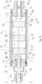
- FIG. 9 shows a cross sectional view longitudinally through a portion of a casting roll with expansion ring 210 with insulating coating 350 thereon spaced from the edge portions of the cast strip and having heating elements 370.
- At least two expansion rings 210 with insulating coating 350 thereon are spaced on opposite end portions of the cylindrical tube 120 within 450 mm of edge portions of the cast strip on opposite end portions of the casting rolls during the casting campaign, and an additional expansion ring 220 with insulating coating 330 thereon is positioned within cylindrical tube 120 at a position corresponding to center portions of the cast strip formed on the casting surfaces during casting.
- expansion ring 220 with insulating coating 330 thereon may be positioned within the cylindrical tube 120, at a position corresponding to center portions of the cast strip formed on the casting surfaces of the casting rolls during casting.
- expansion rings with an insulating coating thereon may be position within and adjacent the cylindrical tube and spaced from the edge portions of the cast strip.
- Each expansion ring may have an annular dimension between 50 and 150 mm; (e.g. 70 mm).
- the expansion ring or rings with an insulating coating thereon positioned at corresponding to center portions of the cast strip formed during casting may have an annular dimension between 50 and 150 mm; (e.g. 70 mm).
- Each expansion ring with an insulating coating spaced from the edge portions of the cast strip may have a width of up to 200 mm (e.g., 83.5 mm).
- the expansion ring or rings with an insulating coating thereon positioned in the center portions of the cast strip during casting may have a width of up to 200 mm (e.g., 83.5 mm).
- Deformation of the crown of the casting surfaces of the casting rolls may be controlled by regulating the radial dimension of the at least one expansion ring located inside the cylindrical tube.
- the radial dimension of the at least one expansion ring with an insulating coating thereon may be controlled by regulating the temperature of the expansion ring.
- the thickness profile of the cast strip may be controlled with the radius of the expansion ring and in turn the crown of the casting surfaces of the casting rolls. Since the circumferential thickness of the cylindrical tube is made to a thickness of no more than 80 mm, the crown of the casting surfaces may be deformed responsive to changes in the radial dimension of the expansion ring.
- Each expansion ring with an insulating coating thereon is adapted to increase in radial dimension causing the cylindrical tube to expand changing the crown of the casting surfaces and the thickness profile of the cast strip during casting.
- Power wire 222 and control wire 224 extend from slip ring 240 to each expansion ring. Power wire 222 supplies electrical power to the expansion ring. Control wire 224 provides the temperature feedback that is then used to control the power of the expansion ring.
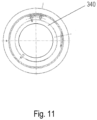
- each expansion ring may have water passages 340 therein wherein water can flow through.
- the water flow may be controlled to regulate the expansion of the expansion rings.
- Each expansion ring may be electrically heated increasing in radial dimension. As illustrated in FIG. 15 , each expansion ring may have at least one heating element positioned as desired to effectively heat the ring. Expansion ring 300 has heating element 310 on the right side and heating element 320 on the left side for that purpose. Each expansion ring may provide a heating input of up to 30 kW; preferably, of at least 3 kW. The force generated from the increase in radial dimension will be applied on the cylindrical tube causing the cylindrical tube to expand changing the crown of the casting surfaces and the thickness profile of the cast strip.
- a strip thickness profile sensor 71 may be positioned downstream to detect the thickness profile of the cast strip 21 as shown in FIGS. 2 and 2A .
- the strip thickness sensor 71 is provided typically between the nip 18 and the pinch rolls 31A to provide for direct control of the casting roll 12.
- the sensor may be an x-ray gauge or other suitable device capable of directly measuring the thickness profile across the width of the strip periodically or continuously.
- a plurality of non-contact type sensors are arranged across the cast strip 21 at the roller table 30 and the combination of thickness measurements from the plurality of positions across the cast strip 21 are processed by a controller 72 to determine the thickness profile of the strip periodically or continuously.
- the thickness profile of the cast strip 21 may be determined from this data periodically or continuously as desired.
- each expansion ring may be controlled independently from the radial dimension of the other expansion ring or rings.
- the radial dimension of the each expansion ring with an insulating coating thereon within and adjacent the strip edges of the casting rolls may be controlled independently from each other.
- the radial dimension of the expansion rings within and adjacent the strip edges of the casting rolls may be controlled independently from the expansion ring or rings with insulating coating thereon corresponding to the center portions of the cast strip.
- the sensor 71 generates signals indicative of the thickness profile of the cast strip.
- the radial dimension of each expansion ring with an insulating coating thereon is controlled according to the signals generated by the sensor, which in turns control roll crown of the casting surfaces of the casting rolls during the casting campaign.
- the casting roll drive may be controlled to vary the speed of rotation of the casting rolls, while also varying the radial dimension of the expansion ring responsive to the electrical signals received from the sensor 71 controlling in turn the roll crown of the casting surfaces of the casting rolls during the casting campaign.
- FIG. 12 shows tests conducted with and without the insulating coating on the expansion rings.
- An insulating coating of 8% Yttria stabilized zirconia was plasma sprayed onto the outside of the expansion ring obtaining an insulating coating of thickness of 0.64 mm (0.025 inch).
- Each expansion ring had a section of casting roll of approximately 85 mm in width shrink fitted on to the expansion ring.
- Each casting roll section had water passages there through. Water was supplied at approximately 1.0 bar (15 psi) and the water flow varied between 8.6 and 8.9 gpm. The inlet water temperature was 20 °C (68 °F). Separate tests were conducted at 50 % power and at 100 % power. As illustrated in FIG.
- FIG. 13 shows a graph of the average expansion ring temperature versus the edge drop.
- the edge drop correlates to the thickness of the cast strip. As illustrated in FIG. 13 , the edge drop appears to respond each time to the changes in the heated expansion ring temperatures. As the temperature increases, the expansion ring expands; the cast trip thickness at the edge of the casting roll decreases and the edge drop increases.
- FIG. 14 shows a graph of heated ring expansion versus temperature for expansion rings coated with an insulating coating.
- the expansion rings were located adjacent and within casting rolls provided with water passages there through and water flowing there through in normal casting operations.
- the coated expansion rings were heated from 29.8 °C to 48.9 °C (85.6 °F to 120 °F). After holding briefly at 48.9 °C (120 °F), the expansion rings with the insulating coating were heated to 71 °C (160 °F) and 93 °C (200 °F). As evidenced, over 100 ⁇ m of dimensional expansion was achieved when the coated expansion rings were heated by 46 °C (115 °F).
- the expansion rings may also have water passages there through to permit the flow of water through the passages in the rings, and regulate the water flow through those passages.
- the water flow is regulated to increase or decrease the diameter of the expansion rings and in turn cylindrical tube as desired, and control the shape of the casting rolls during a campaign.
Landscapes
- Engineering & Computer Science (AREA)
- Mechanical Engineering (AREA)
- Continuous Casting (AREA)
- Control Of Metal Rolling (AREA)
- Metal Rolling (AREA)
Claims (16)
- Procédé de coulée en continu de fines bandes par commande de bombage de rouleau comprenant les étapes consistant à :a. assembler une machine de coulée ayant une paire de rouleaux de coulée contrarotatifs (12) avec une ligne de contact (18) entre eux capable de délivrer la bande coulée vers le bas depuis la ligne de contact (18), chaque rouleau de coulée (12) ayant une surface de coulée (12A) formée par un tube cylindrique (120) ayant une épaisseur de pas plus de 80 millimètres d'un matériau choisi dans le groupe constitué du cuivre et d'un alliage de cuivre, facultativement avec un revêtement métallique ou d'alliage métallique sur celui-ci, et ayant une pluralité de passages d'écoulement d'eau longitudinaux (126) s'étendant à travers le tube cylindrique (120) ;b. le positionnement d'au moins deux bagues de dilatation (210) au sein du tube cylindrique (120) et adjacentes à celui-ci et espacées de 450 mm des portions de bord de la bande coulée formée sur les portions d'extrémité opposées des rouleaux de coulée (12) pendant une campagne de coulée, et/ou le positionnement d'au moins une bague de dilatation (210) au sein du tube cylindrique (120) correspondant aux portions centrales de la bande coulée formée sur les rouleaux de coulée (12) pendant la coulée, chaque bague de dilatation (210) ayant au moins un élément chauffant (370) et un revêtement isolant (350) d'au moins 0,25 mm (0,010 pouce), avec le revêtement isolant (350) étant tel que lorsque le tube cylindrique (120) est refroidi avec les passages d'écoulement d'eau longitudinaux (126) et l'élément chauffant (370) mis en fonctionnement, une dite bague de dilatation (210) avec un revêtement isolant de 0,64 mm (0,025 pouce) est capable d'obtenir une différence de température par rapport au tube cylindrique (120) supérieure d'au moins 67 % à une différence de température qu'une bague de dilatation similaire mais non revêtue pourrait obtenir dans des conditions de fonctionnement similaires ;c. l'assemblage d'un système de distribution de métal capable de former un bain de coulée (19) soutenu sur les surfaces de coulée (12A) des rouleaux de coulée (12) au-dessus de la ligne de contact (18) avec des faces latérales (20) adjacentes aux extrémités de la ligne de contact (18) pour confiner le bain de coulée (19) ; etd. la commande de la dimension radiale des bagues de dilatation (210) en réponse à au moins un signal numérique ou analogique reçu depuis au moins un capteur (71) pour commander le bombage de rouleau des surfaces de coulée (12A) des rouleaux de coulée (12) pendant la campagne de coulée.
- Procédé de coulée en continu de fines bandes par commande de bombage de rouleau selon la revendication 1, comprenant en outre l'étape consistant à :
e. fournir des passages d'eau dans chaque bague de dilatation, dans lequel l'eau peut s'écouler à travers lesdits passages d'eau, et commander ledit écoulement d'eau et réguler la dilatation des bagues de dilatation (210). - Procédé de coulée en continu de fines bandes par commande de bombage de rouleau selon la revendication 1 ou la revendication 2, comprenant en outre l'étape consistant à :
f. positionner au moins un capteur capable de capter au moins l'une des propriétés suivantes :- température des bagues de dilatation (210) ;- profil d'épaisseur de la bande coulée en aval ;- épaisseur locale de la bande coulée à un endroit défini proche des bords de la bande coulée ;- bombé de surface de rouleau de coulée pendant la campagne de coulée ;- dilatation radiale du rouleau de coulée à un endroit défini proche des bords de bande coulée ;et générer un signal ou des signaux numériques ou analogiques indicatifs d'au moins l'une des propriétés susmentionnées de la bande coulée. - Procédé de coulée en continu de fines bandes par commande de bombage de rouleau selon l'une quelconque des revendications précédentes, comprenant en outre l'étape consistant à :
g. commander l'entraînement des rouleaux de coulée pour faire varier la vitesse de rotation des rouleaux de coulée (12) tout en faisant varier la dimension radiale des bagues de dilatation (210) avec un revêtement isolant (350) sur celles-ci en réponse à au moins l'un des signaux numériques ou analogiques reçus depuis
l'au moins un capteur (71) pour commander le bombage de rouleau des surfaces de coulée (12A) des rouleaux de coulée (12) pendant la campagne de coulée. - Procédé de coulée en continu d'une fine bande par commande de bombage de rouleau selon l'une quelconque des revendications précédentes, dans lequel chaque bague de dilatation (210) avec un revêtement isolant (350) sur celle-ci a une dimension annulaire entre 50 et 150 mm.
- Procédé de coulée en continu d'une fine bande par commande de bombage de rouleau selon l'une quelconque des revendications précédentes, dans lequel chaque bague de dilatation (210) avec un revêtement isolant (350) sur celle-ci fournit une puissance de chauffage allant jusqu'à 30 kW.
- Procédé de coulée en continu d'une fine bande par commande de bombage de rouleau selon l'une quelconque des revendications précédentes, dans lequel la dimension radiale de chaque bague de dilatation (210) avec un revêtement isolant (350) sur celle-ci peut être commandée indépendamment par commande indépendante de l'écoulement d'eau à travers les passages d'eau dans chaque bague de dilatation pour commander le bombage de rouleau des surfaces de coulée (12A) des rouleaux de coulée (12).
- Procédé de coulée en continu d'une fine bande par commande de bombage de rouleau selon l'une quelconque des revendications précédentes, comprenant en outre l'étape consistant à :
h. commander la position du rouleau de coulée (12) pour faire varier la distance horizontale entre les lignes centrales axiales de rouleau de coulée tout en faisant varier la dimension radiale des bagues de dilatation (210), chaque bague de dilatation (210) avec un revêtement isolant (350) sur celle-ci correspondant à au moins une propriété dans une portion centrale ou une portion de bord de la bande coulée en réponse à au moins l'un des signaux numériques ou analogiques reçus depuis l'au moins un capteur (71) pour commander le bombage de rouleau des surfaces de coulée (12A) des rouleaux de coulée (12) pendant la campagne de coulée. - Appareil de coulée en continu de fines bandes par commande de bombage de rouleau comprenant :a. une paire de rouleaux de coulée contrarotatifs (12) avec une ligne de contact (18) entre eux capable de délivrer la bande coulée vers le bas depuis la ligne de contact (18), chaque rouleau de coulée (12) ayant une surface de coulée (12A) formée par un tube cylindrique (120) ayant une épaisseur de pas plus de 80 millimètres d'un matériau choisi dans le groupe constitué du cuivre et d'un alliage de cuivre, facultativement avec un revêtement métallique ou d'alliage métallique sur celui-ci, et ayant une pluralité de passages d'écoulement d'eau longitudinaux (126) s'étendant à travers le tube cylindrique (120) ;b. au moins deux bagues de dilatation (210) positionnées au sein du tube cylindrique (120) et adjacentes à celui-ci et espacées de 450 mm des portions de bord de la bande coulée formée sur les portions d'extrémité opposées des rouleaux de coulée (12) pendant une campagne de coulée, et/ou au moins une bague de dilatation (210) au sein du tube cylindrique (120) à une position correspondant aux portions centrales de la bande coulée formée sur les rouleaux de coulée (12) pendant une campagne de coulée, chaque bague de dilatation (210) ayant au moins un élément chauffant (370) et un revêtement isolant (350) d'au moins 0,25 mm (0,010 pouce), avec le revêtement isolant (350) de telle sorte que lorsque le tube cylindrique (120) est refroidi avec les passages d'écoulement d'eau longitudinaux (126) et l'élément chauffant (370) mis en fonctionnement, une dite bague de dilatation avec un revêtement isolant de 0,64 mm (0,025 pouce) est capable d'obtenir une différence de température par rapport au tube cylindrique (120) supérieure d'au moins 67 % à une différence de température qu'une bague de dilatation similaire mais non revêtue pourrait obtenir dans des conditions de fonctionnement similaires ;c. un système de distribution de métal positionné au-dessus de la ligne de contact (18) et capable de former un bain de coulée (19) soutenu sur les surfaces de coulée (12A) des rouleaux de coulée (12) avec des faces latérales (20) adjacentes aux extrémités de la ligne de contact (18) pour confiner le bain de coulée (19) ; etd. au moins un capteur capable de capter le profil d'épaisseur de la bande coulée et capable de générer des signaux électriques indicatifs du profil d'épaisseur de la bande coulée peut être positionné en aval.
- Appareil de coulée en continu de fines bandes par commande de bombage de rouleau selon la revendication 9, comprenant en outre : chaque bague de dilatation (210) ayant des passages d'eau dans lequel l'eau peut s'écouler à travers lesdits passages d'eau (126) et réguler la dilatation de la bague de dilatation (210),
- Appareil de coulée en continu de fines bandes par commande de bombage de rouleau selon la revendication 9 ou la revendication 10, comprenant en outre :
e. au moins un capteur capable de capter au moins l'une des propriétés suivantes :- température des bagues de dilatation (210) ;- profil d'épaisseur de la bande coulée positionnée en aval de la ligne de contact (18) ;- épaisseur locale de la bande coulée à un endroit défini proche des bords de la bande coulée ;- bombé de surface de rouleau de coulée pendant la campagne de coulée ;- dilatation radiale du rouleau de coulée à un endroit défini proche des bords de bande coulée ;et capable de générer un signal ou des signaux numériques ou analogiques indicatifs d'au moins une des propriétés ci-dessus pour commander la dimension radiale des bagues de dilatation (210) en réponse aux signaux reçus depuis l'au moins un capteur pour commander le bombage de rouleau des surfaces de coulée des rouleaux de coulée pendant la campagne de coulée. - Appareil de coulée en continu de fines bandes par commande de bombage de rouleau selon l'une quelconque des revendications 9 à 11, comprenant en outre :
e. un système de commande capable de commander l'entraînement des rouleaux de coulée et de faire varier la vitesse de rotation des rouleaux de coulée (12) tout en faisant varier la dimension radiale des bagues de dilatation (210) avec un revêtement isolant (350) sur celles-ci en réponse aux signaux électriques reçus depuis l'au moins un capteur (71) pour commander le bombage de rouleau des surfaces de coulée (12A) des rouleaux de coulée (12) pendant la campagne de coulée. - Appareil de coulée en continu d'une fine bande par commande de bombage de rouleau selon l'une quelconque des revendications 9 à 12, dans lequel chaque bague de dilatation (210) avec un revêtement isolant (350) sur celle-ci a une dimension annulaire entre 50 et 150 mm.
- Appareil de coulée en continu d'une fine bande par commande de bombage de rouleau selon l'une quelconque des revendications 9 à 13, dans lequel chaque bague de dilatation (210) avec un revêtement isolant (350) sur celle-ci et espacée des portions de bord de la bande coulée a une largeur allant jusqu'à 200 mm.
- Appareil de coulée en continu d'une fine bande par commande de bombage de rouleau selon l'une quelconque des revendications 9 à 14, dans lequel chaque bague de dilatation (210) avec un revêtement isolant (350) sur celle-ci et espacée des portions de bord de la bande coulée fournit une puissance de chauffage allant jusqu'à 30 kW.
- Appareil de coulée en continu d'une fine bande par commande de bombage de rouleau selon l'une quelconque des revendications 9 à 15, dans lequel la dimension radiale de chaque bague de dilatation (210) avec un revêtement isolant (350) sur celle-ci et espacée des portions de bord de la bande coulée peut être commandée indépendamment pour commander le bombage de rouleau des surfaces de coulée (12A) des rouleaux de coulée (12).
Applications Claiming Priority (2)
| Application Number | Priority Date | Filing Date | Title |
|---|---|---|---|
| US14/946,872 US20170144218A1 (en) | 2015-11-20 | 2015-11-20 | Method for casting metal strip with crown control |
| PCT/US2015/063676 WO2017087006A1 (fr) | 2015-11-20 | 2015-12-03 | Procédé de coulée de bande de métal à réglage de bombage |
Publications (4)
| Publication Number | Publication Date |
|---|---|
| EP3377238A1 EP3377238A1 (fr) | 2018-09-26 |
| EP3377238A4 EP3377238A4 (fr) | 2020-01-01 |
| EP3377238B1 true EP3377238B1 (fr) | 2024-10-02 |
| EP3377238C0 EP3377238C0 (fr) | 2024-10-02 |
Family
ID=58717597
Family Applications (1)
| Application Number | Title | Priority Date | Filing Date |
|---|---|---|---|
| EP15908989.5A Active EP3377238B1 (fr) | 2015-11-20 | 2015-12-03 | Procédé de coulée de bande de métal à réglage de bombage |
Country Status (8)
| Country | Link |
|---|---|
| US (2) | US20170144218A1 (fr) |
| EP (1) | EP3377238B1 (fr) |
| JP (2) | JP2018538142A (fr) |
| KR (1) | KR102469642B1 (fr) |
| CN (1) | CN108602099A (fr) |
| MX (2) | MX2018006201A (fr) |
| SA (1) | SA518391587B1 (fr) |
| WO (1) | WO2017087006A1 (fr) |
Families Citing this family (8)
| Publication number | Priority date | Publication date | Assignee | Title |
|---|---|---|---|---|
| WO2018232231A1 (fr) * | 2017-06-15 | 2018-12-20 | Nucor Corporation | Procédé de coulée d'une bande métallique à réglage de bord |
| US10449603B2 (en) | 2017-09-22 | 2019-10-22 | Nucor Corporation | Iterative learning control for periodic disturbances in twin-roll strip casting with measurement delay |
| EP3556488A1 (fr) * | 2018-04-19 | 2019-10-23 | Primetals Technologies Austria GmbH | Rouleau de coulée et procédé de coulée de bande de métal avec commande de couronne |
| CN111069553B (zh) * | 2019-12-16 | 2021-08-31 | 武汉科技大学 | 一种连铸坯的质量改进方法 |
| DE102021206617B3 (de) * | 2021-06-25 | 2022-09-08 | Volkswagen Aktiengesellschaft | Vorrichtung zur Herstellung einer Elektrodenanordnung für eine Lithium-Ionen-Batteriezelle |
| CN115971436B (zh) * | 2023-03-16 | 2023-05-26 | 张家港中美超薄带科技有限公司 | 一种控制薄带钢凸度的方法 |
| CN116372125B (zh) * | 2023-03-16 | 2026-01-02 | 张家港中美超薄带科技有限公司 | 一种通过结晶辊温度控制薄带钢凸度的方法 |
| CN116372124B (zh) * | 2023-03-16 | 2025-12-23 | 张家港中美超薄带科技有限公司 | 一种通过核心水口位置控制薄带钢凸度的方法 |
Family Cites Families (23)
| Publication number | Priority date | Publication date | Assignee | Title |
|---|---|---|---|---|
| US3358485A (en) * | 1965-02-15 | 1967-12-19 | United States Steel Corp | Measuring and controlling gap between rolls |
| US4008750A (en) * | 1975-04-15 | 1977-02-22 | Alcan Research And Development Limited | Continuous casting of metals |
| JPS6050120U (ja) * | 1983-09-14 | 1985-04-09 | 朝日印刷紙器株式会社 | 異形物仕切付収納箱 |
| US4588021A (en) * | 1983-11-07 | 1986-05-13 | Hazelett Strip-Casting Corporation | Matrix coatings on endless flexible metallic belts for continuous casting machines method of forming such coatings and the coated belts |
| JPS6418511A (en) * | 1987-07-15 | 1989-01-23 | Kobe Steel Ltd | Thermal crown control type rolling roll |
| JP2600318B2 (ja) * | 1988-08-16 | 1997-04-16 | 石川島播磨重工業株式会社 | 双ロール連鋳機のロール面形状の修正制御方法 |
| JPH02280909A (ja) * | 1989-04-24 | 1990-11-16 | Nippon Steel Corp | 圧延ロールおよびその圧延ロールを用いた圧延方法 |
| US5626183A (en) * | 1989-07-14 | 1997-05-06 | Fata Hunter, Inc. | System for a crown control roll casting machine |
| JPH0382718A (ja) * | 1989-08-28 | 1991-04-08 | Sumitomo Metal Ind Ltd | 熱クラウン抑制ハースロール |
| JP3035587B2 (ja) * | 1992-07-22 | 2000-04-24 | 株式会社日立製作所 | 連続鋳造装置及び連続鋳造方法 |
| JPH07204792A (ja) * | 1994-01-24 | 1995-08-08 | Mitsubishi Heavy Ind Ltd | ツインドラム式連続鋳造装置 |
| JPH07256402A (ja) * | 1994-03-22 | 1995-10-09 | Nippon Steel Corp | 双ロール式連続鋳造機 |
| FR2723014B1 (fr) * | 1994-07-29 | 1996-09-20 | Pechiney Rhenalu | Procede et dispositif de correction de l'ovalisation de cylindres de coulee continue de bande metallique |
| FR2732627B1 (fr) * | 1995-04-07 | 1997-04-30 | Usinor Sacilor | Procede et dispositif de reglage du bombe des cylindres d'une installation de coulee de bandes metalliques |
| AUPO832897A0 (en) | 1997-07-30 | 1997-08-28 | Bhp Steel (Jla) Pty Limited | Twin roll casting |
| AUPP852499A0 (en) * | 1999-02-05 | 1999-03-04 | Bhp Steel (Jla) Pty Limited | Casting metal strip |
| AUPQ291199A0 (en) * | 1999-09-17 | 1999-10-07 | Bhp Steel (Jla) Pty Limited | Strip casting |
| CH695089A5 (de) * | 2001-09-18 | 2005-12-15 | Main Man Inspiration Ag | Giessrolle für eine Zweirollen-Giessmaschine. |
| US8607848B2 (en) * | 2008-08-05 | 2013-12-17 | Nucor Corporation | Method for casting metal strip with dynamic crown control |
| US8607847B2 (en) * | 2008-08-05 | 2013-12-17 | Nucor Corporation | Method for casting metal strip with dynamic crown control |
| EP2975010B1 (fr) * | 2014-07-14 | 2016-08-17 | Refractory Intellectual Property GmbH & Co. KG | Oxyde de zirconium, utilisation d'oxyde de zirconium et procédé de fabrication d'un produit réfractaire |
| WO2016083506A1 (fr) * | 2014-11-28 | 2016-06-02 | Siemens Vai Metals Technologies Gmbh | Procédé de coulée d'une bande métallique à réglage de couronne |
| CN104550794B (zh) * | 2014-12-05 | 2017-04-12 | 澳洲澳秀科技有限公司 | 连铸机中使用的水冷结晶辊 |
-
2015
- 2015-11-20 US US14/946,872 patent/US20170144218A1/en not_active Abandoned
- 2015-12-03 EP EP15908989.5A patent/EP3377238B1/fr active Active
- 2015-12-03 KR KR1020187017320A patent/KR102469642B1/ko active Active
- 2015-12-03 WO PCT/US2015/063676 patent/WO2017087006A1/fr not_active Ceased
- 2015-12-03 JP JP2018525434A patent/JP2018538142A/ja active Pending
- 2015-12-03 CN CN201580085717.3A patent/CN108602099A/zh active Pending
- 2015-12-03 MX MX2018006201A patent/MX2018006201A/es unknown
-
2018
- 2018-05-15 SA SA518391587A patent/SA518391587B1/ar unknown
- 2018-05-18 MX MX2023012056A patent/MX2023012056A/es unknown
-
2020
- 2020-09-23 US US17/029,983 patent/US20210001396A1/en active Pending
-
2021
- 2021-01-29 JP JP2021012927A patent/JP7109607B2/ja not_active Expired - Fee Related
Also Published As
| Publication number | Publication date |
|---|---|
| US20210001396A1 (en) | 2021-01-07 |
| JP2021062411A (ja) | 2021-04-22 |
| MX2023012056A (es) | 2023-10-23 |
| EP3377238A1 (fr) | 2018-09-26 |
| EP3377238C0 (fr) | 2024-10-02 |
| CN108602099A (zh) | 2018-09-28 |
| JP2018538142A (ja) | 2018-12-27 |
| EP3377238A4 (fr) | 2020-01-01 |
| KR20180084940A (ko) | 2018-07-25 |
| US20170144218A1 (en) | 2017-05-25 |
| MX2018006201A (es) | 2018-08-01 |
| KR102469642B1 (ko) | 2022-11-22 |
| SA518391587B1 (ar) | 2022-09-21 |
| WO2017087006A1 (fr) | 2017-05-26 |
| JP7109607B2 (ja) | 2022-07-29 |
Similar Documents
| Publication | Publication Date | Title |
|---|---|---|
| EP3377238B1 (fr) | Procédé de coulée de bande de métal à réglage de bombage | |
| EP3204177B1 (fr) | Procédé de coulée d'une bande métallique à réglage de couronne | |
| US8607848B2 (en) | Method for casting metal strip with dynamic crown control | |
| EP3548207B1 (fr) | Rouleau de coulée et procédé de coulée d'une bande métallique à réglage de couronne | |
| US11148193B2 (en) | Method for casting metal strip with edge control | |
| US8607847B2 (en) | Method for casting metal strip with dynamic crown control |
Legal Events
| Date | Code | Title | Description |
|---|---|---|---|
| STAA | Information on the status of an ep patent application or granted ep patent |
Free format text: STATUS: THE INTERNATIONAL PUBLICATION HAS BEEN MADE |
|
| PUAI | Public reference made under article 153(3) epc to a published international application that has entered the european phase |
Free format text: ORIGINAL CODE: 0009012 |
|
| STAA | Information on the status of an ep patent application or granted ep patent |
Free format text: STATUS: REQUEST FOR EXAMINATION WAS MADE |
|
| 17P | Request for examination filed |
Effective date: 20180618 |
|
| AK | Designated contracting states |
Kind code of ref document: A1 Designated state(s): AL AT BE BG CH CY CZ DE DK EE ES FI FR GB GR HR HU IE IS IT LI LT LU LV MC MK MT NL NO PL PT RO RS SE SI SK SM TR |
|
| AX | Request for extension of the european patent |
Extension state: BA ME |
|
| DAV | Request for validation of the european patent (deleted) | ||
| DAX | Request for extension of the european patent (deleted) | ||
| A4 | Supplementary search report drawn up and despatched |
Effective date: 20191204 |
|
| RIC1 | Information provided on ipc code assigned before grant |
Ipc: B21B 37/32 20060101AFI20191128BHEP Ipc: B22D 11/06 20060101ALI20191128BHEP Ipc: B22D 11/16 20060101ALI20191128BHEP |
|
| STAA | Information on the status of an ep patent application or granted ep patent |
Free format text: STATUS: EXAMINATION IS IN PROGRESS |
|
| 17Q | First examination report despatched |
Effective date: 20210319 |
|
| GRAP | Despatch of communication of intention to grant a patent |
Free format text: ORIGINAL CODE: EPIDOSNIGR1 |
|
| STAA | Information on the status of an ep patent application or granted ep patent |
Free format text: STATUS: GRANT OF PATENT IS INTENDED |
|
| INTG | Intention to grant announced |
Effective date: 20240604 |
|
| GRAS | Grant fee paid |
Free format text: ORIGINAL CODE: EPIDOSNIGR3 |
|
| GRAA | (expected) grant |
Free format text: ORIGINAL CODE: 0009210 |
|
| STAA | Information on the status of an ep patent application or granted ep patent |
Free format text: STATUS: THE PATENT HAS BEEN GRANTED |
|
| AK | Designated contracting states |
Kind code of ref document: B1 Designated state(s): AL AT BE BG CH CY CZ DE DK EE ES FI FR GB GR HR HU IE IS IT LI LT LU LV MC MK MT NL NO PL PT RO RS SE SI SK SM TR |
|
| REG | Reference to a national code |
Ref country code: GB Ref legal event code: FG4D |
|
| REG | Reference to a national code |
Ref country code: CH Ref legal event code: EP |
|
| REG | Reference to a national code |
Ref country code: IE Ref legal event code: FG4D |
|
| REG | Reference to a national code |
Ref country code: DE Ref legal event code: R096 Ref document number: 602015090058 Country of ref document: DE |
|
| U01 | Request for unitary effect filed |
Effective date: 20241030 |
|
| U07 | Unitary effect registered |
Designated state(s): AT BE BG DE DK EE FI FR IT LT LU LV MT NL PT RO SE SI Effective date: 20241210 |
|
| U20 | Renewal fee for the european patent with unitary effect paid |
Year of fee payment: 10 Effective date: 20241227 |
|
| PG25 | Lapsed in a contracting state [announced via postgrant information from national office to epo] |
Ref country code: IS Free format text: LAPSE BECAUSE OF FAILURE TO SUBMIT A TRANSLATION OF THE DESCRIPTION OR TO PAY THE FEE WITHIN THE PRESCRIBED TIME-LIMIT Effective date: 20250202 Ref country code: HR Free format text: LAPSE BECAUSE OF FAILURE TO SUBMIT A TRANSLATION OF THE DESCRIPTION OR TO PAY THE FEE WITHIN THE PRESCRIBED TIME-LIMIT Effective date: 20241002 |
|
| PG25 | Lapsed in a contracting state [announced via postgrant information from national office to epo] |
Ref country code: ES Free format text: LAPSE BECAUSE OF FAILURE TO SUBMIT A TRANSLATION OF THE DESCRIPTION OR TO PAY THE FEE WITHIN THE PRESCRIBED TIME-LIMIT Effective date: 20241002 |
|
| PG25 | Lapsed in a contracting state [announced via postgrant information from national office to epo] |
Ref country code: NO Free format text: LAPSE BECAUSE OF FAILURE TO SUBMIT A TRANSLATION OF THE DESCRIPTION OR TO PAY THE FEE WITHIN THE PRESCRIBED TIME-LIMIT Effective date: 20250102 |
|
| PG25 | Lapsed in a contracting state [announced via postgrant information from national office to epo] |
Ref country code: GR Free format text: LAPSE BECAUSE OF FAILURE TO SUBMIT A TRANSLATION OF THE DESCRIPTION OR TO PAY THE FEE WITHIN THE PRESCRIBED TIME-LIMIT Effective date: 20250103 |
|
| PG25 | Lapsed in a contracting state [announced via postgrant information from national office to epo] |
Ref country code: CZ Free format text: LAPSE BECAUSE OF FAILURE TO SUBMIT A TRANSLATION OF THE DESCRIPTION OR TO PAY THE FEE WITHIN THE PRESCRIBED TIME-LIMIT Effective date: 20241002 Ref country code: PL Free format text: LAPSE BECAUSE OF FAILURE TO SUBMIT A TRANSLATION OF THE DESCRIPTION OR TO PAY THE FEE WITHIN THE PRESCRIBED TIME-LIMIT Effective date: 20241002 |
|
| PGFP | Annual fee paid to national office [announced via postgrant information from national office to epo] |
Ref country code: GB Payment date: 20250128 Year of fee payment: 10 |
|
| PG25 | Lapsed in a contracting state [announced via postgrant information from national office to epo] |
Ref country code: RS Free format text: LAPSE BECAUSE OF FAILURE TO SUBMIT A TRANSLATION OF THE DESCRIPTION OR TO PAY THE FEE WITHIN THE PRESCRIBED TIME-LIMIT Effective date: 20250102 |
|
| PG25 | Lapsed in a contracting state [announced via postgrant information from national office to epo] |
Ref country code: SM Free format text: LAPSE BECAUSE OF FAILURE TO SUBMIT A TRANSLATION OF THE DESCRIPTION OR TO PAY THE FEE WITHIN THE PRESCRIBED TIME-LIMIT Effective date: 20241002 |
|
| PG25 | Lapsed in a contracting state [announced via postgrant information from national office to epo] |
Ref country code: MC Free format text: LAPSE BECAUSE OF FAILURE TO SUBMIT A TRANSLATION OF THE DESCRIPTION OR TO PAY THE FEE WITHIN THE PRESCRIBED TIME-LIMIT Effective date: 20241002 |
|
| PG25 | Lapsed in a contracting state [announced via postgrant information from national office to epo] |
Ref country code: SK Free format text: LAPSE BECAUSE OF FAILURE TO SUBMIT A TRANSLATION OF THE DESCRIPTION OR TO PAY THE FEE WITHIN THE PRESCRIBED TIME-LIMIT Effective date: 20241002 |
|
| REG | Reference to a national code |
Ref country code: CH Ref legal event code: PL |
|
| PLBE | No opposition filed within time limit |
Free format text: ORIGINAL CODE: 0009261 |
|
| STAA | Information on the status of an ep patent application or granted ep patent |
Free format text: STATUS: NO OPPOSITION FILED WITHIN TIME LIMIT |
|
| 26N | No opposition filed |
Effective date: 20250703 |
|
| PG25 | Lapsed in a contracting state [announced via postgrant information from national office to epo] |
Ref country code: CH Free format text: LAPSE BECAUSE OF NON-PAYMENT OF DUE FEES Effective date: 20241231 |
|
| PG25 | Lapsed in a contracting state [announced via postgrant information from national office to epo] |
Ref country code: IE Free format text: LAPSE BECAUSE OF NON-PAYMENT OF DUE FEES Effective date: 20241203 |
|
| PGFP | Annual fee paid to national office [announced via postgrant information from national office to epo] |
Ref country code: TR Payment date: 20251212 Year of fee payment: 11 |
|
| PG25 | Lapsed in a contracting state [announced via postgrant information from national office to epo] |
Ref country code: CY Free format text: LAPSE BECAUSE OF FAILURE TO SUBMIT A TRANSLATION OF THE DESCRIPTION OR TO PAY THE FEE WITHIN THE PRESCRIBED TIME-LIMIT; INVALID AB INITIO Effective date: 20151203 |
|
| U21 | Renewal fee for the european patent with unitary effect paid with additional fee |
Year of fee payment: 11 Effective date: 20260224 |
|
| U1N | Appointed representative for the unitary patent procedure changed after the registration of the unitary effect |
Representative=s name: VENNER SHIPLEY LLP; GB |