EP3377394B1 - Aktiver deflektor - Google Patents
Aktiver deflektor Download PDFInfo
- Publication number
- EP3377394B1 EP3377394B1 EP16809482.9A EP16809482A EP3377394B1 EP 3377394 B1 EP3377394 B1 EP 3377394B1 EP 16809482 A EP16809482 A EP 16809482A EP 3377394 B1 EP3377394 B1 EP 3377394B1
- Authority
- EP
- European Patent Office
- Prior art keywords
- deflector
- spl
- wheel
- whl
- actuator
- Prior art date
- Legal status (The legal status is an assumption and is not a legal conclusion. Google has not performed a legal analysis and makes no representation as to the accuracy of the status listed.)
- Active
Links
Images


Classifications
-
- B—PERFORMING OPERATIONS; TRANSPORTING
- B62—LAND VEHICLES FOR TRAVELLING OTHERWISE THAN ON RAILS
- B62D—MOTOR VEHICLES; TRAILERS
- B62D35/00—Vehicle bodies characterised by streamlining
- B62D35/005—Front spoilers
-
- B—PERFORMING OPERATIONS; TRANSPORTING
- B62—LAND VEHICLES FOR TRAVELLING OTHERWISE THAN ON RAILS
- B62D—MOTOR VEHICLES; TRAILERS
- B62D35/00—Vehicle bodies characterised by streamlining
- B62D35/02—Streamlining the undersurfaces
-
- B—PERFORMING OPERATIONS; TRANSPORTING
- B62—LAND VEHICLES FOR TRAVELLING OTHERWISE THAN ON RAILS
- B62D—MOTOR VEHICLES; TRAILERS
- B62D37/00—Stabilising vehicle bodies without controlling suspension arrangements
- B62D37/02—Stabilising vehicle bodies without controlling suspension arrangements by aerodynamic means
-
- Y—GENERAL TAGGING OF NEW TECHNOLOGICAL DEVELOPMENTS; GENERAL TAGGING OF CROSS-SECTIONAL TECHNOLOGIES SPANNING OVER SEVERAL SECTIONS OF THE IPC; TECHNICAL SUBJECTS COVERED BY FORMER USPC CROSS-REFERENCE ART COLLECTIONS [XRACs] AND DIGESTS
- Y02—TECHNOLOGIES OR APPLICATIONS FOR MITIGATION OR ADAPTATION AGAINST CLIMATE CHANGE
- Y02T—CLIMATE CHANGE MITIGATION TECHNOLOGIES RELATED TO TRANSPORTATION
- Y02T10/00—Road transport of goods or passengers
- Y02T10/80—Technologies aiming to reduce greenhouse gasses emissions common to all road transportation technologies
- Y02T10/82—Elements for improving aerodynamics
-
- Y—GENERAL TAGGING OF NEW TECHNOLOGICAL DEVELOPMENTS; GENERAL TAGGING OF CROSS-SECTIONAL TECHNOLOGIES SPANNING OVER SEVERAL SECTIONS OF THE IPC; TECHNICAL SUBJECTS COVERED BY FORMER USPC CROSS-REFERENCE ART COLLECTIONS [XRACs] AND DIGESTS
- Y02—TECHNOLOGIES OR APPLICATIONS FOR MITIGATION OR ADAPTATION AGAINST CLIMATE CHANGE
- Y02T—CLIMATE CHANGE MITIGATION TECHNOLOGIES RELATED TO TRANSPORTATION
- Y02T10/00—Road transport of goods or passengers
- Y02T10/80—Technologies aiming to reduce greenhouse gasses emissions common to all road transportation technologies
- Y02T10/88—Optimized components or subsystems, e.g. lighting, actively controlled glasses
Definitions
- the invention particularly relates to a deflection device placed in front of a motor vehicle wheel.
- the aerodynamics of a motor vehicle is an important feature because it influences in particular the fuel consumption (and therefore the pollution) as well as the performance of said vehicle. This is particularly important when the motor vehicle is traveling at high speed.
- the drag force exerted on a motor vehicle is quantified using a reference surface S.
- the drag force denoted Fx
- Fx the drag force
- q * S * Cx the drag force
- Cx denoting a drag coefficient specific to the vehicle.
- the reference surface used for a motor vehicle is usually its front surface. To reduce drag, it is common to reduce the reference area. But to reduce the drag even more, it is possible to influence other parameters.
- AGS from the English language expression "Active Grille Shutter”, or active calender shutter.
- AGS from the English language expression "Active Grille Shutter”, or active calender shutter.
- the device makes it possible to open or close the air access via a motor vehicle grille. In the open position, the air can circulate through the shell and participate in cooling the engine of the motor vehicle. In the closed position, the air does not enter via the grille which reduces the drag.
- the wheel arch is a cavity built into the body of the vehicle, and surrounding a wheel (this corresponds to the wing of the vehicle).
- the wheel arch fulfills several functions. In particular, it limits (by retaining them) projections of water, mud or other materials on which the wheel is likely to circulate and that it may be caused to expel during its rotation.
- an external fairing has only limited effectiveness and a fixed deflector may be damaged during obstacle clearance (sidewalk, speed bump type, etc.).
- the invention aims to improve the situation.
- the invention relates to a deflection device adapted to be fixed upstream with respect to the air flow of a motor vehicle wheel in order to reduce the aerodynamic drag of said wheel, the device comprising a deflector and a actuator, the actuator being arranged to deploy and retract the deflector in front of said wheel.
- a deflection device adapted to be fixed upstream with respect to the air flow of a motor vehicle wheel in order to reduce the aerodynamic drag of said wheel
- the device comprising a deflector and a actuator, the actuator being arranged to deploy and retract the deflector in front of said wheel.
- Such a deflection device is advantageous in particular in that it makes it possible to ensure a reduction of the drag at the level of the wheel and that it is able to guard against the damage related to obstacles being crossed by the wheel. .
- the deflector is provided with at least one air passage shutter, the device being arranged to open each shutter when the actuator starts to deploy the deflector, and to close each shutter when the actuator finishes deploying the deflector.
- the invention relates in particular to a deflection device in which each shutter comprises a plate arranged to slide in the deflector plane, the plate being provided with at least one opening.
- the invention relates in particular to a deflection device in which each shutter comprises a flap.
- the invention relates in particular to a deflection device in which the actuator of the device is arranged to open and to close each shutter.
- the invention relates in particular to a deflection device wherein the baffle is rotatable about an axis parallel to the axis of the wheel.
- the invention relates in particular to a deflection device in which the deflector has the same width as the wheel.
- the invention relates in particular to a deflection device arranged to control the deployment of the deflector when the speed of the device exceeds a predetermined threshold, and to control the retraction of the deflector when said speed passes below a predetermined threshold.
- the invention relates in particular to a deflection device arranged to deploy the deflector to a distance of about 80mm from the ground on which the wheel rests.
- the invention relates in particular to a deflection device in which the deflector is placed in a horizontal position relative to the ground on which the wheel rests when it is in the retracted position.
- the invention relates in particular to a deflection device in which the deflector is placed in an inclined position relative to the ground on which rests the wheel when in the deployed position.
- the invention also relates to a method for controlling aerodynamic drag affecting a motor vehicle wheel, comprising a step of deploying such a deflector in front of said wheel with the aid of an actuator in order to reduce said drag, and a step of retracting said deflector with said actuator when the reduction of said drag is no longer appropriate.
- This method constitutes an advantageous use of a deflection device according to one embodiment of the invention.
- the Figure 1A illustrates a vertical section of a motor vehicle in a longitudinal direction of the vehicle.
- the vehicle is shown in displacement situation.
- a relative wind AIR therefore exerts pressure on the vehicle.
- This relative wind creates turbulence TRB in a wheel well WH (in English, "wheelhouse") of the vehicle.
- the vehicle includes a deflector device including an SPL baffle and an ACT actuator.
- ACT actuator is for example a servomotor or any suitable electric motor.
- ACT actuator is shown schematically.
- the SPL deflector shown takes the form of a straight cylinder portion articulated at the axis of symmetry of the right cylinder.
- the represented SPL deflector comprises six shutters SHT (English, "shutter”). It totally retracted, and the SHT shutters are closed.
- the Figure 1B illustrates the motor vehicle of the Figure 1A , in front view. Only the left half of the vehicle is shown. We see on this Figure 1B , as on the Figure 1A , that the WHL wheel is not protected by the SPL deflector, which is fully retracted.
- the Figure 2A represents the vehicle of the Figure 1A (according to the same vertical section as on the Figure 1A ), in which SPL deflector is partially (half) deployed.
- the six SHT flaps are open to allow the relative wind AIR to pass and to limit ACT actuator effort required to continue deploying the SPL baffle.
- the Figure 2B illustrates the motor vehicle of the Figure 2A , in front view. Only the left half of the vehicle is shown.
- the wheel WHL is partially protected by the deflector SPL, which is partially deployed, and which lets pass a part of the relative wind.
- the six SHT shutters represented as parallel segments. The surfaces that make up these six flaps are substantially parallel to the ground on which the vehicle is moving, in order to offer a minimum resistance to the relative wind during deployment of the deflector. In front view, they appear schematically as horizontal segments.
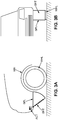
- the figure 3A represents the vehicle of Figures 1A and 2A , according to the same vertical section, in which SPL deflector is fully deployed.
- the six SHT flaps are closed, so as to deflect the relative wind and to prevent as much as possible the entry of the relative wind into the wheel well WH.
- the figure 3B illustrates the motor vehicle of the figure 3A , in front view. Only the left half of the vehicle is shown.
- the WHL wheel is largely protected by the SPL deflector, which is fully deployed. This full deployment occurs over most of the height separating the ground on which circulates the motor vehicle of the axis of rotation of the deflector (which is in this case at the rocker).
- the six shutters SHT which are closed, collectively form a continuous surface, airtight. They are not reproduced in the figure because not visible in a schematic representation.
- the SPL deflector thus deviates most of the relative wind, and protects the wheel well from turbulence that would otherwise lead to a much greater aerodynamic drag.
- a first embodiment relates to a deflection device.
- the device is adapted to be fixed in front of a wheel WHL of a motor vehicle, in order to reduce the aerodynamic drag of said wheel WHL.
- the device includes an SPL baffle. It further comprises an actuator ACT arranged to deploy the deflector SPL in front of said wheel WHL, as well as to retract said deflector SPL in front of said wheel WHL.
- the SPL deflector is located upstream of the WHL wheel with respect to the flow of air.
- front is meant that the deflector SPL is between the front of the motor vehicle (for example its front bumper) and the wheel WHL.
- the deflector is deployed by resorting to a rotational movement of said reflector.
- the deflector is deployed via a translational movement of said reflector.
- the deflector can thus take the form of a guided plate along a pair of rails.
- the deflector SPL of a device according to the first embodiment is provided with at least one air passage shutter, the device being arranged to open each shutter when the actuator begins to deploy the SPL baffle, and to close each shutter when the actuator finishes deploying the SPL baffle.
- the shutter can take various forms.
- the deflector comprises a single shutter.
- the deflector comprises several shutters, which are either all identical or different from each other.
- each shutter of a device comprises a plate arranged to slide in the plane of the deflector, a portion of the plate being provided with at least one opening.
- the wafer is rectangular in shape, half of the rectangle being full (and therefore airtight), the other half comprising one or more holes.
- the baffle comprises, for example, a plate forming a plane whose so-called outer face is exposed to air, and of which a so-called internal opposite face comprises guide rails for the one or more wafers.
- This plate is, according to one possible implementation, provided, for each shutter, a respective window.
- Each window may in particular consist of an orifice having the shape of a disk or a parallelepiped.
- Each plate arranged to slide parallel to this plate, lets the air pass when its opening (or its openings if it has more than one) is at the level of the respective window, but prevents the passage of air when the formed surface by its opening has no intersection with the surface of the respective window.
- the SPL deflector of a device according to the first embodiment is provided with SHT flaps.
- the device is arranged to open the SHT flaps when the actuator begins to deploy the SPL baffle, and to close the SHT flaps when the actuator finishes deploying the SPL baffle.
- the SHT flaps are immediately opened.
- a more gradual opening is also possible.
- the SHT flaps are only closed when the deflector is deployed when this deployment is completed.
- the closure of the SHT flaps is more gradual and begins before complete completion of the deflector deployment. It is possible to combine an immediate opening with a progressive closure, and reciprocally a progressive opening with an immediate closure.
- the device keeps the SHT flaps substantially parallel to the ground on which the vehicle is traveling during the entire deployment of the deflector, which may involve varying an orientation command of these flaps throughout the deployment.
- the kinematics flaps is symmetrical to that of the deployment phase of the deflector. This can be advantageous from the point of view of the simplicity of the device.
- the SHT flaps are kept closed during the retraction of the SPL deflector.
- the effort required to retract the reflector can be reduced by taking advantage of the force resulting from the relative wind. This is particularly the case when the deployment and retraction of the deflector result from a rotational movement as illustrated on the Figures 1A , 2A and 3A .
- the actuator ACT of a device is arranged to open and close each shutter. It can thus close the shutters SHT, when the shutters take the form of shutters.
- This is advantageous because it simplifies the construction of the deflector device which requires only one ACT actuator to drive both the SPL deflector and its SHT flaps.
- a kinematics of retraction of the deflector symmetrical deflector deployment kinematics is simpler to implement an asymmetrical kinematics as envisaged in a variant above.
- the deflector SPL of a device according to one of the first to fifth embodiments is rotatable about an axis parallel to the axis of the wheel WHL. This allows the deployment and retraction of the SPL baffle by a rotational movement.
- the Figures 1A to 3A illustrate such an embodiment.
- the SPL deflector of a device according to one of the first to sixth embodiments has the same width as the WHL wheel. This is advantageous because it makes it possible not to increase the reference surface of the vehicle, which is decisive for the aerodynamic drag.
- a device is arranged to control the deployment of the deflector SPL when the speed of the device exceeds a predetermined threshold, and to control the retraction of the deflector SPL when said speed passes under a predetermined threshold.
- the device comprises for example an electronic circuit such as a microprocessor or a microcontroller receiving a speed information from a speed sensor, and ordering deployment deploying or retracting the baffle accordingly.
- a hysteresis mechanism is provided in order to avoid threshold effects.
- the actuator triggers the deployment of the deflector as soon as the speed exceeds a given threshold (for example 50km / h), but that the actuator only triggers the retraction of the deflector when the speed drops below a threshold lower than the aforementioned threshold (for example a threshold of 40km / h).
- the circuit avoids inadvertently trigger alternations of deployment and retraction when the vehicle is traveling at a speed close to the initial threshold and passes permanently from one side to the other of this threshold.
- the deployment trigger (eg 50km / h) is chosen to be high enough for deployment to have a noticeable effect on aerodynamic drag.
- the drag varies with the square of the speed. For low speeds, the drag itself is very low. Deploying the baffle is not helpful.
- the triggering threshold of the retraction (for example 40 km / h) is chosen so as to be high enough so that the driver can not reasonably consider crossing obstacles (sidewalks, speed bumps, etc.) at the speed considered. Thus, it prevents the motor vehicle is brought to cross such an obstacle (such as to damage the deflector) while the deflector is deployed.
- a device is arranged to deploy the deflector to a distance of about 80 mm from the ground on which the WHL wheel rests.
- the distance considered is the distance, in a direction perpendicular to the ground on which the motor vehicle is traveling, between the lowest point of the deflector and the ground.
- the extent of the deployment is adjustable (eg using a screw), in order to choose a distance value to the ground in a given range (for example between 60mm and 100mm).
- the deflector is provided with a distance sensor.
- the device is then arranged to interrupt deployment of the deflector when a low end of the deflector reaches a predefined distance (for example 80mm from the ground).
- a predefined distance for example 80mm from the ground.
- Such a sensor may be advantageous in the event that there is a significant margin in the fixing position of the deflection device on the motor vehicle in question.
- Such a sensor may also be advantageous in the event that the deflection device is likely to be installed on different types of vehicles. In these cases, the deflection device does not necessarily know its distance to the ground, and the sensor allows to set the deployment limit automatically without having to adjust.
- the distance sensor can (in addition or alternatively) order a retraction (possibly partial) when it detects that the deflector is too close to the ground, even if the vehicle would travel at a speed greater than the retraction threshold. This can happen if the vehicle crosses an obstacle at high speed. This can prevent damage to the baffle if the actuator is fast enough.
- the distance sensor can be used to disengage the deflector if it is too close to the ground.
- the declutching would spontaneously lead to retract somewhat the deflector (thanks to the relative wind), and would collect any impact with the ground without damaging the actuator (disengaged), and limiting the damage to the deflector.
- the SPL deflector of a device is placed in a horizontal position relative to the ground on which the WHL wheel rests when it is in the retracted position.
- the surface of the deflector which is exposed to the relative wind is assumed to be flat.
- the position horizontal is then defined relative to the plane of the deflector which is exposed to the relative wind. The position is said to be horizontal when this plane is substantially parallel to the ground on which the motor vehicle is traveling.
- the eventual SHT flaps of the deflector are closed. This is advantageous and avoids the penetration of various pollutants (water, dust, mud, etc.) from outside the vehicle through the openings that would open SHT flaps.
- the SPL deflector of a device is placed in an inclined position relative to the ground on which the WHL wheel rests when it is in the deployed position.
- the surface of the deflector which is exposed to the relative wind is assumed to be flat.
- the inclination of the deflector is then defined relative to the plane of the deflector which is exposed to the relative wind.
- the baffle may be tilted about 135 ° to the ground, as shown in the illustration. figure 3A .
- the position is said inclined when it is neither horizontal nor vertical.
- a method for controlling aerodynamic drag affecting a motor vehicle WHL wheel comprises a step of deploying an SPL deflector in front of said wheel WHL with the aid of an actuator ACT. This makes it possible to reduce said drag.
- the method further comprises a step of retracting said deflector SPL to using said actuator ACT when the reduction of said drag is no longer appropriate.
- the method can implement the various functions of the deflection device described above. In particular, it can control the deflector deployment stop using a distance sensor, control the opening and closing of any deflector flaps, etc.
Landscapes
- Engineering & Computer Science (AREA)
- Chemical & Material Sciences (AREA)
- Combustion & Propulsion (AREA)
- Transportation (AREA)
- Mechanical Engineering (AREA)
- Physics & Mathematics (AREA)
- Fluid Mechanics (AREA)
- Cooling, Air Intake And Gas Exhaust, And Fuel Tank Arrangements In Propulsion Units (AREA)
- Body Structure For Vehicles (AREA)
Claims (11)
- Luftleitvorrichtung, die stromaufwärts bezüglich der Luftströmung eines Rads (WHL) eines Kraftfahrzeugs befestigt werden kann, wobei die Vorrichtung ein Leitblech (SPL) und einen Stellantrieb (ACT) enthält, wobei der Stellantrieb (ACT) eingerichtet ist, um das Leitblech (SPL) vor dem Rad (WHL) aus- und einzufahren, dadurch gekennzeichnet, dass das Leitblech (SPL) mit mindestens einem Luftdurchgangsverschluss versehen ist, wobei die Vorrichtung eingerichtet ist, um jeden Verschluss zu öffnen, wenn der Stellantrieb beginnt, das Leitblech (SPL) auszufahren, und um jeden Verschluss zu schließen, wenn der Stellantrieb das Ausfahren des Leitblechs (SPL) beendet.
- Vorrichtung nach Anspruch 1, wobei jeder Verschluss eine Platte enthält, die eingerichtet ist, um in der Ebene des Leitblechs zu gleiten, wobei die Platte mit mindestens einer Öffnung versehen ist.
- Vorrichtung nach Anspruch 1, wobei jeder Verschluss eine Klappe (SHT) enthält.
- Vorrichtung nach einem der Ansprüche 1 bis 3, wobei der Stellantrieb (ACT) der Vorrichtung eingerichtet ist, um jeden Verschluss zu öffnen und zu schließen.
- Vorrichtung nach einem der vorhergehenden Ansprüche, wobei das Leitblech (SPL) um eine Achse parallel zur Achse des Rads (WHL) drehbeweglich ist.
- Vorrichtung nach einem der vorhergehenden Ansprüche, wobei das Leitblech (SPL) die gleiche Breite hat wie das Rad (WHL).
- Vorrichtung nach einem der vorhergehenden Ansprüche, die eingerichtet ist, um das Ausfahren des Leitblechs (SPL) zu steuern, wenn die Geschwindigkeit der Vorrichtung eine vorbestimmte Schwelle überschreitet, und um das Einfahren des Leitblechs (SPL) zu steuern, wenn die Geschwindigkeit unter eine vorbestimmte Schwelle geht.
- Vorrichtung nach einem der vorhergehenden Ansprüche, die eingerichtet ist, um das Leitblech bis zu einem Abstand von etwa 80 mm vom Boden auszufahren, auf dem das Rad (WHL) aufliegt.
- Vorrichtung nach einem der vorhergehenden Ansprüche, wobei das Leitblech (SPL) bezüglich des Bodens, auf dem das Rad (WHL) aufliegt, in waagrechter Stellung angeordnet ist, wenn es in der eingefahrenen Stellung ist.
- Vorrichtung nach einem der vorhergehenden Ansprüche, wobei das Leitblech (SPL) bezüglich des Bodens, auf dem das Rad (WHL) aufliegt, in geneigter Stellung angeordnet ist, wenn es in der ausgefahrenen Stellung ist.
- Verfahren zur Kontrolle des aerodynamischen Widerstands, der ein Rad (WHL) eines Kraftfahrzeugs beeinträchtigt, das einen Schritt des Ausfahrens eines Leitblechs (SPL) nach einem der vorhergehenden Ansprüche vor dem Rad (WHL) mit Hilfe eines Stellantriebs (ACT), um den Widerstand zu verringern, und einen Schritt des Einfahrens des Leitblechs (SPL) mit Hilfe des Stellantriebs (ACT) enthält, wenn die Verringerung des Widerstands nicht mehr zweckmäßig ist.
Applications Claiming Priority (2)
| Application Number | Priority Date | Filing Date | Title |
|---|---|---|---|
| FR1561093A FR3043634B1 (fr) | 2015-11-18 | 2015-11-18 | Deflecteur actif |
| PCT/FR2016/052893 WO2017085375A1 (fr) | 2015-11-18 | 2016-11-08 | Deflecteur actif |
Publications (2)
| Publication Number | Publication Date |
|---|---|
| EP3377394A1 EP3377394A1 (de) | 2018-09-26 |
| EP3377394B1 true EP3377394B1 (de) | 2019-12-11 |
Family
ID=55361666
Family Applications (1)
| Application Number | Title | Priority Date | Filing Date |
|---|---|---|---|
| EP16809482.9A Active EP3377394B1 (de) | 2015-11-18 | 2016-11-08 | Aktiver deflektor |
Country Status (3)
| Country | Link |
|---|---|
| EP (1) | EP3377394B1 (de) |
| FR (1) | FR3043634B1 (de) |
| WO (1) | WO2017085375A1 (de) |
Cited By (2)
| Publication number | Priority date | Publication date | Assignee | Title |
|---|---|---|---|---|
| CN109131590A (zh) * | 2017-06-19 | 2019-01-04 | 丰田自动车株式会社 | 车辆底部结构 |
| US12503170B2 (en) | 2022-11-21 | 2025-12-23 | Ford Global Technologies, Llc | Dynamically deployable adaptive mud flaps |
Families Citing this family (5)
| Publication number | Priority date | Publication date | Assignee | Title |
|---|---|---|---|---|
| FR3066453B1 (fr) * | 2017-05-16 | 2019-08-16 | Compagnie Plastic Omnium | Volet aerodynamique de sous-bassement retractable avec reprise d'effort par l'appui bas |
| DE102017128791B4 (de) | 2017-12-05 | 2022-04-28 | Dr. Ing. H.C. F. Porsche Aktiengesellschaft | Frontdiffusor für ein Fahrzeug |
| KR102540890B1 (ko) * | 2018-10-29 | 2023-06-08 | 현대자동차주식회사 | 회전가림 방식 휠 가드 시스템 및 차량 |
| FR3088294B1 (fr) * | 2018-11-14 | 2022-07-08 | Valeo Systemes Thermiques | Dispositif deflecteur pour roue de vehicule automobile et vehicule comprenant un tel dispositif |
| CN116409394A (zh) * | 2021-12-29 | 2023-07-11 | 本田技研工业株式会社 | 车辆下部结构 |
Family Cites Families (6)
| Publication number | Priority date | Publication date | Assignee | Title |
|---|---|---|---|---|
| JP3094575B2 (ja) * | 1991-10-15 | 2000-10-03 | 三菱自動車工業株式会社 | 車両用可動スパッツ |
| JPH0840315A (ja) * | 1995-06-26 | 1996-02-13 | Nippondenso Co Ltd | 横風用エアスポイラー装置 |
| JPH10278854A (ja) * | 1997-04-09 | 1998-10-20 | Toyota Motor Corp | 車両用可動スパッツ制御装置 |
| FR2858793B1 (fr) * | 2003-08-13 | 2006-12-01 | Peugeot Citroen Automobiles Sa | Element aerodynamique pour la reduction de la trainee et de la portance d'un vehicule automobile |
| JP4701885B2 (ja) * | 2005-07-12 | 2011-06-15 | アイシン精機株式会社 | 可動エアバランス装置 |
| DE102006009681A1 (de) * | 2006-03-02 | 2007-09-06 | Bayerische Motoren Werke Ag | Fahrzeug mit einem Luftleitelement |
-
2015
- 2015-11-18 FR FR1561093A patent/FR3043634B1/fr not_active Expired - Fee Related
-
2016
- 2016-11-08 EP EP16809482.9A patent/EP3377394B1/de active Active
- 2016-11-08 WO PCT/FR2016/052893 patent/WO2017085375A1/fr not_active Ceased
Cited By (3)
| Publication number | Priority date | Publication date | Assignee | Title |
|---|---|---|---|---|
| CN109131590A (zh) * | 2017-06-19 | 2019-01-04 | 丰田自动车株式会社 | 车辆底部结构 |
| CN109131590B (zh) * | 2017-06-19 | 2021-08-03 | 丰田自动车株式会社 | 车辆底部结构 |
| US12503170B2 (en) | 2022-11-21 | 2025-12-23 | Ford Global Technologies, Llc | Dynamically deployable adaptive mud flaps |
Also Published As
| Publication number | Publication date |
|---|---|
| FR3043634A1 (fr) | 2017-05-19 |
| EP3377394A1 (de) | 2018-09-26 |
| WO2017085375A1 (fr) | 2017-05-26 |
| FR3043634B1 (fr) | 2019-03-22 |
Similar Documents
| Publication | Publication Date | Title |
|---|---|---|
| EP3377394B1 (de) | Aktiver deflektor | |
| EP3390209B1 (de) | Aerodynamische ablenkvorrichtung für kraftfahrzeugrad | |
| EP2734392B1 (de) | Schliessvorrichtung einer öffnung einer kraftfahrzeugvorderverkleidung | |
| EP3416874B1 (de) | Aerodynamischer deflektor für ein kraftfahrzeugrad | |
| EP3786034B1 (de) | Vorrichtung zum steuern der luftströme und fahrzeug, das eine solche vorrichtung umfasst | |
| FR3045000A1 (fr) | Dispositif deflecteur aerodynamique pour roue de vehicule automobile | |
| WO2016092165A1 (fr) | Dispositif de déflexion d'air à paroi à rotation contrôlée par des ressorts antagonistes dont l'un est déformable par effet joule | |
| WO2017013047A1 (fr) | Dispositif d'obturation d'une entree d air, en particulier positionnee sur la face avant d'un vehicule tel qu'un vehicule automobile | |
| EP3426544B1 (de) | Raddeflektor und entsprechendes frontendmodul | |
| FR2959473A1 (fr) | Vehicule automobile comportant des moyens aerodynamiques positionnes en avant d'une roue et de son dispositif de freinage | |
| FR3071471A1 (fr) | Dispositif deflecteur de vehicule automobile | |
| EP3359406B1 (de) | Frontendmodulträger und zugehöriges frontendmodul | |
| FR2963773A1 (fr) | Vehicule automobile equipe d'un dispositif de controle d'ecoulement d'air arriere pilote selon des etats de fonctionnement d'autres equipements embarques | |
| EP3812216B1 (de) | Einziehbare rückwärtsfahrkamera in einem beweglichen spoiler | |
| FR3052712A1 (fr) | Dispositif de regulation d’un flux d’air circulant au travers d’une ouverture menagee dans un pare-chocs de vehicule automobile | |
| FR3146651A1 (fr) | Système dynamique de réduction de la trainée et de la portance d'un véhicule automobile | |
| FR3040662A1 (fr) | Dispositif d'obturation d'entree d'air de face avant de vehicule automobile et module de face avant pour vehicule automobile | |
| FR3107248A1 (fr) | Déflecteur de custode rotatif couplé à un conduit | |
| WO2019106101A1 (fr) | Dispositif deflecteur a paroi comprenant un moyen d'amenee d'air en aval de la paroi | |
| WO2017162944A1 (fr) | Volet debrayable par vis sans fin | |
| EP4240607A1 (de) | Kühlmodul für ein elektro- oder hybridkraftfahrzeug mit einer tangentialflussturbomaschine | |
| WO2019223917A1 (fr) | Dispositif déflecteur aérodynamique situé à l'avant d'un véhicule automobile | |
| FR2848522A1 (fr) | Vehicule automobile equipe d'un dispositif a plaque de reduction de trainee aerodynamique | |
| FR3067319B1 (fr) | Mecanisme de deployement d''un ensemble de generateurs de vortex | |
| FR2957582A1 (fr) | Vehicule equipe d'un element aerodynamique mobile pilote selon des etats de fonctionnement d'autres equipements embarques. |
Legal Events
| Date | Code | Title | Description |
|---|---|---|---|
| STAA | Information on the status of an ep patent application or granted ep patent |
Free format text: STATUS: UNKNOWN |
|
| STAA | Information on the status of an ep patent application or granted ep patent |
Free format text: STATUS: THE INTERNATIONAL PUBLICATION HAS BEEN MADE |
|
| PUAI | Public reference made under article 153(3) epc to a published international application that has entered the european phase |
Free format text: ORIGINAL CODE: 0009012 |
|
| STAA | Information on the status of an ep patent application or granted ep patent |
Free format text: STATUS: REQUEST FOR EXAMINATION WAS MADE |
|
| 17P | Request for examination filed |
Effective date: 20180605 |
|
| AK | Designated contracting states |
Kind code of ref document: A1 Designated state(s): AL AT BE BG CH CY CZ DE DK EE ES FI FR GB GR HR HU IE IS IT LI LT LU LV MC MK MT NL NO PL PT RO RS SE SI SK SM TR |
|
| AX | Request for extension of the european patent |
Extension state: BA ME |
|
| DAV | Request for validation of the european patent (deleted) | ||
| DAX | Request for extension of the european patent (deleted) | ||
| GRAP | Despatch of communication of intention to grant a patent |
Free format text: ORIGINAL CODE: EPIDOSNIGR1 |
|
| STAA | Information on the status of an ep patent application or granted ep patent |
Free format text: STATUS: GRANT OF PATENT IS INTENDED |
|
| INTG | Intention to grant announced |
Effective date: 20190725 |
|
| GRAS | Grant fee paid |
Free format text: ORIGINAL CODE: EPIDOSNIGR3 |
|
| GRAA | (expected) grant |
Free format text: ORIGINAL CODE: 0009210 |
|
| STAA | Information on the status of an ep patent application or granted ep patent |
Free format text: STATUS: THE PATENT HAS BEEN GRANTED |
|
| AK | Designated contracting states |
Kind code of ref document: B1 Designated state(s): AL AT BE BG CH CY CZ DE DK EE ES FI FR GB GR HR HU IE IS IT LI LT LU LV MC MK MT NL NO PL PT RO RS SE SI SK SM TR |
|
| REG | Reference to a national code |
Ref country code: GB Ref legal event code: FG4D Free format text: NOT ENGLISH |
|
| REG | Reference to a national code |
Ref country code: CH Ref legal event code: EP |
|
| REG | Reference to a national code |
Ref country code: AT Ref legal event code: REF Ref document number: 1211926 Country of ref document: AT Kind code of ref document: T Effective date: 20191215 |
|
| REG | Reference to a national code |
Ref country code: DE Ref legal event code: R096 Ref document number: 602016026146 Country of ref document: DE |
|
| REG | Reference to a national code |
Ref country code: IE Ref legal event code: FG4D Free format text: LANGUAGE OF EP DOCUMENT: FRENCH |
|
| REG | Reference to a national code |
Ref country code: NL Ref legal event code: MP Effective date: 20191211 |
|
| REG | Reference to a national code |
Ref country code: LT Ref legal event code: MG4D |
|
| PG25 | Lapsed in a contracting state [announced via postgrant information from national office to epo] |
Ref country code: SE Free format text: LAPSE BECAUSE OF FAILURE TO SUBMIT A TRANSLATION OF THE DESCRIPTION OR TO PAY THE FEE WITHIN THE PRESCRIBED TIME-LIMIT Effective date: 20191211 Ref country code: LV Free format text: LAPSE BECAUSE OF FAILURE TO SUBMIT A TRANSLATION OF THE DESCRIPTION OR TO PAY THE FEE WITHIN THE PRESCRIBED TIME-LIMIT Effective date: 20191211 Ref country code: LT Free format text: LAPSE BECAUSE OF FAILURE TO SUBMIT A TRANSLATION OF THE DESCRIPTION OR TO PAY THE FEE WITHIN THE PRESCRIBED TIME-LIMIT Effective date: 20191211 Ref country code: GR Free format text: LAPSE BECAUSE OF FAILURE TO SUBMIT A TRANSLATION OF THE DESCRIPTION OR TO PAY THE FEE WITHIN THE PRESCRIBED TIME-LIMIT Effective date: 20200312 Ref country code: NO Free format text: LAPSE BECAUSE OF FAILURE TO SUBMIT A TRANSLATION OF THE DESCRIPTION OR TO PAY THE FEE WITHIN THE PRESCRIBED TIME-LIMIT Effective date: 20200311 Ref country code: FI Free format text: LAPSE BECAUSE OF FAILURE TO SUBMIT A TRANSLATION OF THE DESCRIPTION OR TO PAY THE FEE WITHIN THE PRESCRIBED TIME-LIMIT Effective date: 20191211 Ref country code: BG Free format text: LAPSE BECAUSE OF FAILURE TO SUBMIT A TRANSLATION OF THE DESCRIPTION OR TO PAY THE FEE WITHIN THE PRESCRIBED TIME-LIMIT Effective date: 20200311 |
|
| PG25 | Lapsed in a contracting state [announced via postgrant information from national office to epo] |
Ref country code: HR Free format text: LAPSE BECAUSE OF FAILURE TO SUBMIT A TRANSLATION OF THE DESCRIPTION OR TO PAY THE FEE WITHIN THE PRESCRIBED TIME-LIMIT Effective date: 20191211 Ref country code: RS Free format text: LAPSE BECAUSE OF FAILURE TO SUBMIT A TRANSLATION OF THE DESCRIPTION OR TO PAY THE FEE WITHIN THE PRESCRIBED TIME-LIMIT Effective date: 20191211 |
|
| PG25 | Lapsed in a contracting state [announced via postgrant information from national office to epo] |
Ref country code: AL Free format text: LAPSE BECAUSE OF FAILURE TO SUBMIT A TRANSLATION OF THE DESCRIPTION OR TO PAY THE FEE WITHIN THE PRESCRIBED TIME-LIMIT Effective date: 20191211 |
|
| PG25 | Lapsed in a contracting state [announced via postgrant information from national office to epo] |
Ref country code: CZ Free format text: LAPSE BECAUSE OF FAILURE TO SUBMIT A TRANSLATION OF THE DESCRIPTION OR TO PAY THE FEE WITHIN THE PRESCRIBED TIME-LIMIT Effective date: 20191211 Ref country code: RO Free format text: LAPSE BECAUSE OF FAILURE TO SUBMIT A TRANSLATION OF THE DESCRIPTION OR TO PAY THE FEE WITHIN THE PRESCRIBED TIME-LIMIT Effective date: 20191211 Ref country code: PT Free format text: LAPSE BECAUSE OF FAILURE TO SUBMIT A TRANSLATION OF THE DESCRIPTION OR TO PAY THE FEE WITHIN THE PRESCRIBED TIME-LIMIT Effective date: 20200506 Ref country code: EE Free format text: LAPSE BECAUSE OF FAILURE TO SUBMIT A TRANSLATION OF THE DESCRIPTION OR TO PAY THE FEE WITHIN THE PRESCRIBED TIME-LIMIT Effective date: 20191211 Ref country code: NL Free format text: LAPSE BECAUSE OF FAILURE TO SUBMIT A TRANSLATION OF THE DESCRIPTION OR TO PAY THE FEE WITHIN THE PRESCRIBED TIME-LIMIT Effective date: 20191211 Ref country code: ES Free format text: LAPSE BECAUSE OF FAILURE TO SUBMIT A TRANSLATION OF THE DESCRIPTION OR TO PAY THE FEE WITHIN THE PRESCRIBED TIME-LIMIT Effective date: 20191211 |
|
| PG25 | Lapsed in a contracting state [announced via postgrant information from national office to epo] |
Ref country code: IS Free format text: LAPSE BECAUSE OF FAILURE TO SUBMIT A TRANSLATION OF THE DESCRIPTION OR TO PAY THE FEE WITHIN THE PRESCRIBED TIME-LIMIT Effective date: 20200411 Ref country code: SK Free format text: LAPSE BECAUSE OF FAILURE TO SUBMIT A TRANSLATION OF THE DESCRIPTION OR TO PAY THE FEE WITHIN THE PRESCRIBED TIME-LIMIT Effective date: 20191211 Ref country code: SM Free format text: LAPSE BECAUSE OF FAILURE TO SUBMIT A TRANSLATION OF THE DESCRIPTION OR TO PAY THE FEE WITHIN THE PRESCRIBED TIME-LIMIT Effective date: 20191211 |
|
| REG | Reference to a national code |
Ref country code: DE Ref legal event code: R097 Ref document number: 602016026146 Country of ref document: DE |
|
| REG | Reference to a national code |
Ref country code: AT Ref legal event code: MK05 Ref document number: 1211926 Country of ref document: AT Kind code of ref document: T Effective date: 20191211 |
|
| PLBE | No opposition filed within time limit |
Free format text: ORIGINAL CODE: 0009261 |
|
| STAA | Information on the status of an ep patent application or granted ep patent |
Free format text: STATUS: NO OPPOSITION FILED WITHIN TIME LIMIT |
|
| PG25 | Lapsed in a contracting state [announced via postgrant information from national office to epo] |
Ref country code: DK Free format text: LAPSE BECAUSE OF FAILURE TO SUBMIT A TRANSLATION OF THE DESCRIPTION OR TO PAY THE FEE WITHIN THE PRESCRIBED TIME-LIMIT Effective date: 20191211 |
|
| 26N | No opposition filed |
Effective date: 20200914 |
|
| PG25 | Lapsed in a contracting state [announced via postgrant information from national office to epo] |
Ref country code: AT Free format text: LAPSE BECAUSE OF FAILURE TO SUBMIT A TRANSLATION OF THE DESCRIPTION OR TO PAY THE FEE WITHIN THE PRESCRIBED TIME-LIMIT Effective date: 20191211 Ref country code: SI Free format text: LAPSE BECAUSE OF FAILURE TO SUBMIT A TRANSLATION OF THE DESCRIPTION OR TO PAY THE FEE WITHIN THE PRESCRIBED TIME-LIMIT Effective date: 20191211 |
|
| PG25 | Lapsed in a contracting state [announced via postgrant information from national office to epo] |
Ref country code: IT Free format text: LAPSE BECAUSE OF FAILURE TO SUBMIT A TRANSLATION OF THE DESCRIPTION OR TO PAY THE FEE WITHIN THE PRESCRIBED TIME-LIMIT Effective date: 20191211 |
|
| PG25 | Lapsed in a contracting state [announced via postgrant information from national office to epo] |
Ref country code: PL Free format text: LAPSE BECAUSE OF FAILURE TO SUBMIT A TRANSLATION OF THE DESCRIPTION OR TO PAY THE FEE WITHIN THE PRESCRIBED TIME-LIMIT Effective date: 20191211 |
|
| PG25 | Lapsed in a contracting state [announced via postgrant information from national office to epo] |
Ref country code: MC Free format text: LAPSE BECAUSE OF FAILURE TO SUBMIT A TRANSLATION OF THE DESCRIPTION OR TO PAY THE FEE WITHIN THE PRESCRIBED TIME-LIMIT Effective date: 20191211 |
|
| REG | Reference to a national code |
Ref country code: CH Ref legal event code: PL |
|
| GBPC | Gb: european patent ceased through non-payment of renewal fee |
Effective date: 20201108 |
|
| PG25 | Lapsed in a contracting state [announced via postgrant information from national office to epo] |
Ref country code: LU Free format text: LAPSE BECAUSE OF NON-PAYMENT OF DUE FEES Effective date: 20201108 |
|
| REG | Reference to a national code |
Ref country code: BE Ref legal event code: MM Effective date: 20201130 |
|
| PG25 | Lapsed in a contracting state [announced via postgrant information from national office to epo] |
Ref country code: LI Free format text: LAPSE BECAUSE OF NON-PAYMENT OF DUE FEES Effective date: 20201130 Ref country code: CH Free format text: LAPSE BECAUSE OF NON-PAYMENT OF DUE FEES Effective date: 20201130 |
|
| PG25 | Lapsed in a contracting state [announced via postgrant information from national office to epo] |
Ref country code: IE Free format text: LAPSE BECAUSE OF NON-PAYMENT OF DUE FEES Effective date: 20201108 |
|
| PG25 | Lapsed in a contracting state [announced via postgrant information from national office to epo] |
Ref country code: GB Free format text: LAPSE BECAUSE OF NON-PAYMENT OF DUE FEES Effective date: 20201108 |
|
| PG25 | Lapsed in a contracting state [announced via postgrant information from national office to epo] |
Ref country code: TR Free format text: LAPSE BECAUSE OF FAILURE TO SUBMIT A TRANSLATION OF THE DESCRIPTION OR TO PAY THE FEE WITHIN THE PRESCRIBED TIME-LIMIT Effective date: 20191211 Ref country code: MT Free format text: LAPSE BECAUSE OF FAILURE TO SUBMIT A TRANSLATION OF THE DESCRIPTION OR TO PAY THE FEE WITHIN THE PRESCRIBED TIME-LIMIT Effective date: 20191211 Ref country code: CY Free format text: LAPSE BECAUSE OF FAILURE TO SUBMIT A TRANSLATION OF THE DESCRIPTION OR TO PAY THE FEE WITHIN THE PRESCRIBED TIME-LIMIT Effective date: 20191211 |
|
| PG25 | Lapsed in a contracting state [announced via postgrant information from national office to epo] |
Ref country code: MK Free format text: LAPSE BECAUSE OF FAILURE TO SUBMIT A TRANSLATION OF THE DESCRIPTION OR TO PAY THE FEE WITHIN THE PRESCRIBED TIME-LIMIT Effective date: 20191211 |
|
| PG25 | Lapsed in a contracting state [announced via postgrant information from national office to epo] |
Ref country code: BE Free format text: LAPSE BECAUSE OF NON-PAYMENT OF DUE FEES Effective date: 20201130 |
|
| P01 | Opt-out of the competence of the unified patent court (upc) registered |
Effective date: 20230528 |
|
| PGFP | Annual fee paid to national office [announced via postgrant information from national office to epo] |
Ref country code: FR Payment date: 20231124 Year of fee payment: 8 Ref country code: DE Payment date: 20231107 Year of fee payment: 8 |
|
| REG | Reference to a national code |
Ref country code: DE Ref legal event code: R119 Ref document number: 602016026146 Country of ref document: DE |
|
| PG25 | Lapsed in a contracting state [announced via postgrant information from national office to epo] |
Ref country code: DE Free format text: LAPSE BECAUSE OF NON-PAYMENT OF DUE FEES Effective date: 20250603 |
|
| PG25 | Lapsed in a contracting state [announced via postgrant information from national office to epo] |
Ref country code: FR Free format text: LAPSE BECAUSE OF NON-PAYMENT OF DUE FEES Effective date: 20241130 |