EP3377437B1 - Vorrichtung zum ausstossen eines korkens aus einem korkenzieher und korkenzieher mit solch einer ausstossvorrichtung - Google Patents
Vorrichtung zum ausstossen eines korkens aus einem korkenzieher und korkenzieher mit solch einer ausstossvorrichtung Download PDFInfo
- Publication number
- EP3377437B1 EP3377437B1 EP16809943.0A EP16809943A EP3377437B1 EP 3377437 B1 EP3377437 B1 EP 3377437B1 EP 16809943 A EP16809943 A EP 16809943A EP 3377437 B1 EP3377437 B1 EP 3377437B1
- Authority
- EP
- European Patent Office
- Prior art keywords
- sliding sleeve
- sleeve
- fixed sleeve
- corkscrew
- ejection device
- Prior art date
- Legal status (The legal status is an assumption and is not a legal conclusion. Google has not performed a legal analysis and makes no representation as to the accuracy of the status listed.)
- Active
Links
Images


Classifications
-
- B—PERFORMING OPERATIONS; TRANSPORTING
- B67—OPENING, CLOSING OR CLEANING BOTTLES, JARS OR SIMILAR CONTAINERS; LIQUID HANDLING
- B67B—APPLYING CLOSURE MEMBERS TO BOTTLES JARS, OR SIMILAR CONTAINERS; OPENING CLOSED CONTAINERS
- B67B7/00—Hand- or power-operated devices for opening closed containers
- B67B7/02—Hand- or power-operated devices for opening closed containers for removing stoppers
- B67B7/04—Cork-screws
- B67B7/0417—Cork-screws with supporting means for assisting the pulling action
- B67B7/0441—Cork-screws with supporting means for assisting the pulling action whereby the supporting means abut around the whole periphery of the neck of the bottle
-
- B—PERFORMING OPERATIONS; TRANSPORTING
- B67—OPENING, CLOSING OR CLEANING BOTTLES, JARS OR SIMILAR CONTAINERS; LIQUID HANDLING
- B67B—APPLYING CLOSURE MEMBERS TO BOTTLES JARS, OR SIMILAR CONTAINERS; OPENING CLOSED CONTAINERS
- B67B7/00—Hand- or power-operated devices for opening closed containers
- B67B7/02—Hand- or power-operated devices for opening closed containers for removing stoppers
- B67B7/04—Cork-screws
-
- B—PERFORMING OPERATIONS; TRANSPORTING
- B67—OPENING, CLOSING OR CLEANING BOTTLES, JARS OR SIMILAR CONTAINERS; LIQUID HANDLING
- B67B—APPLYING CLOSURE MEMBERS TO BOTTLES JARS, OR SIMILAR CONTAINERS; OPENING CLOSED CONTAINERS
- B67B7/00—Hand- or power-operated devices for opening closed containers
- B67B7/02—Hand- or power-operated devices for opening closed containers for removing stoppers
- B67B7/04—Cork-screws
- B67B7/0405—Power-operated cork-screws, e.g. operated by an electric motor
Definitions
- the subject of the present invention is a device for ejecting a cork from a corkscrew of the type comprising a body traversed by a passage of tubular appearance defining a housing in which is received a swirl capable of being driven in rotation. around the longitudinal axis of said body by means of a gripping element connected to one of its ends and extending outside of said body.
- the invention also relates to a corkscrew, of the type comprising a body traversed by a passage of tubular appearance defining a housing in which a cork is received, equipped with such a device for ejecting a cork.
- the released cork should then fall from the body of the corkscrew by gravity in order to be able to be recovered, for example in the hand of the user placed under the corkscrew, and then to allow a new use of the corkscrew.
- a stopper in particular when it is made of a friable material such as cork, can be damaged by the somewhat brutal treatment to which it is inevitably subjected during its forced extraction. This can then prohibit its possible subsequent reuse to close a bottle that has only been partially opened, and force the user to obtain a spare cap, which may, if necessary, prove to be of lesser quality.
- a corkscrew comprising the technical characteristics of the preamble of claim 1 is known from CN 101 081 684 B .
- the object of the present invention is to overcome the said drawbacks by proposing a solution allowing a user to extract easily, and successfully at each attempt, a cork retained in the body of a corkscrew without having to insert his fingers into that -this, or to have to push the cork with the twist, therefore in a secure manner, and while preserving the structural integrity of the cork concerned.
- the present invention relates to a device for ejecting a cork from a corkscrew of the type indicated in the preamble, said device comprising a cradle of tubular appearance capable of being accommodated in the housing of a corkscrew.
- said cradle being formed of a fixed sleeve intended to be secured to said body of the corkscrew and of a sliding sleeve, movable in translation relative to the fixed sleeve, between a position in which it is fully fitted into the fixed sleeve and a position in which it is at least partially extracted from said fixed sleeve, said fixed sleeves and slide having a high end and a low end considering a vertical position of the ejection device, and said sliding sleeve comprising means capable of exerting, on a cork retained in said corkscrew, a force oriented in the direction of the end bottom of the fixed sleeve, when it is brought to its position in which it is at least partially extracted from said fixed sleeve.
- the invention also relates to a corkscrew comprising a hollow body providing a housing in which is received a swirl capable of being driven in rotation about the longitudinal axis of said body by means of a gripping element connected to the one of its ends and extending outside of said body, said housing being capable of receiving a cap screwed onto the auger and having, in the vicinity of the free end of the auger, at least one portion of circular section capable of be fitted onto the neck of a bottle, characterized in that it comprises a device for ejecting a cork as defined above.
- the corkscrew 1 comprises a body 2 of generally tubular appearance, the outer wall of which is solid and which can be made of a material such as in particular wood, a metal, a plastic, a composite material, or any other equivalent material that is both solid and aesthetic.
- the body 2 internally delimits a housing 5 able to house a twist 3 intended to be driven in rotation around the longitudinal axis of the body 2 by a user manipulating a gripping element, such as a handle 4 emerging from the body 2 and connected to one end of auger 3.
- the corkscrew 1 is moreover equipped with a device for ejecting a cork 7 which remains housed in the housing 5 after its extraction from a bottle 11.
- the ejection device comprises a cradle 6, tubular in appearance.
- the housing 5 and the cradle 6 have a complementary shape allowing them to fit together.
- the cradle 6 is also shaped so as to be able to accommodate the auger 3 and a plug 7 screwed into the auger 3.
- the cradle 6 can be made of a material such as for example a plastic, a composite material, a material ceramic, metal or other equivalent material.
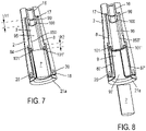
- the cradle 6 is formed of a fixed sleeve 8 intended to be secured to the body 2 of the corkscrew 1 and of a sliding sleeve 9, movable in translation relative to the fixed sleeve 8, between a position in which it is fully fitted and housed in the fixed sleeve 8 (cf. for example fig. 5 ) and a position in which it is at least partially extracted from the fixed sleeve 8 (cf. fig. 6 ).
- the fixed 8 and sliding 9 sleeves have a high end 80, 90 and a low end 81, 91 considering a vertical position of the cradle 6. They each have a first section 82, 92, whose section is provided capable of receiving, in a tight manner, a plug 7 screwed onto the auger 3 and a second section 83, 93, of section greater than that of the first section 82, 92 capable of being fitted onto the neck 10 of a closed container by the stopper 7, such as a bottle 11.
- Each of the fixed 8 and sliding 9 sleeves thus has a shoulder 84, 94 formed between its first section 82, 92 and its second section 83, 93.
- the peripheral wall of the fixed sleeve 8 comprises on the one hand two strips of material 85, 85', the external faces of which are curved while the internal faces 850, 850' are flat in appearance.
- These two strips of material 85, 85' are symmetrical with respect to the axis of the fixed sleeve 8 and extend over its first section 82 between its upper end 80 and its shoulder 84. Their internal faces 850, 850' are spaced 'a distance dl allowing the tightening of a cap 7.
- the strips of material 85, 85' extend under the shoulder 84 and thus define two fins 101, 101' of height h2 extending at the level of the upper end of the second section 83 of the fixed sleeve 8.
- the strips of material 85, 85' define two longitudinal slots 86, 86' also extending between the upper end 80 and the shoulder 84 of the first section 82 .
- the peripheral wall of the fixed sleeve 8 further comprises two strips of material 87, 87' symmetrical with respect to the axis of the fixed sleeve 8 and extending over its second section 83 between its shoulder 84 and its lower end 81, delimiting two longitudinal slots 88, 88' (cf. fig. 2 ).
- the strips of material 87, 87' of the second section 83 of the fixed sleeve 8 have curved internal faces, spaced apart by a diameter d2 and have a width 12 greater than the width 11 of the strips of material 85, 85' of the first section 82 , and chosen so as to give an identical width to all of the longitudinal slots 86, 86', 88, 88' of the fixed sleeve 8.
- the sliding sleeve 9 has a peripheral wall complementary to that of the fixed handle 8. Indeed, it comprises on each of its first and second sections 92, 93 two strips of material 95, 95', 97, 97' extending respectively between its upper end 90 and the shoulder 94, and between the latter and its lower end 91. These strips of material 95, 95', 97, 97' are complementary to the longitudinal slots 86, 86', 88, 88' of the fixed sleeve 8 and thus delimit on the sliding sleeve 9 longitudinal slots 96, 96', 98, 98' complementary to the strips of material 85, 85', 87, 87' of the fixed sleeve 8.
- strips of material 85, 85', 87, 87', 95, 95', 97, 97' have straight longitudinal edges.
- the two fixed 8 and sliding 9 sleeves can be fitted together, their respective strips of material 85, 85', 87, 87', 95, 95', 97, 97' being inserted into their longitudinal slots 86, 86', 88, 88', 96, 96', 98, 98' and therefore being in contact with each other at their respective rectilinear longitudinal edges.
- the latter define, as will be described in more detail below, first means for guiding the sliding sleeve 9 in translation relative to the fixed sleeve 8.
- the sliding sleeve 9 is locked in rotation relative to the fixed sleeve 8 thanks to the contact between the respective longitudinal edges of the strips of material 85, 85', 87, 87', 95, 95', 97, 97' whatever its position relative to the fixed sleeve 8.
- the upper end 90 of the sliding sleeve 9 is also closed by a lid 99 having a central orifice 12 able to allow the passage of the auger 3 when the cradle 6 is fitted into the body 2 of the puller. cap 1.
- the edge of the lid 99 of the sliding sleeve 9 has two opposite grooves 13, centered in the extension of each of the longitudinal slots 96, 96'. They are provided capable of cooperating, when the two sleeves 8, 9 are nested, with two opposite longitudinal ribs 14, centered on the flat inner face 850, 850' of each of the complementary strips 85, 85' of the peripheral wall of the first section 82 of the fixed sleeve 8, intended to be received in said slot 96, 96'.
- the assembly formed by the two grooves 13 of the sliding sleeve 9 and the two longitudinal ribs 14 of the fixed sleeve 8 defines second means for guiding the sliding sleeve 9 in translation relative to the fixed sleeve 8.
- the ribs 14 also make it possible to block a stopper 7 in rotation, housed in the part of the corkscrew 1 formed by the first sections 82, 92 of the fixed 8 and sliding 9 sleeves, after its extraction of a bottle 11, during the unscrewing of the auger 3.
- a stopper 7 in rotation housed in the part of the corkscrew 1 formed by the first sections 82, 92 of the fixed 8 and sliding 9 sleeves, after its extraction of a bottle 11, during the unscrewing of the auger 3.
- other means of blocking the stopper 7 in rotation can be envisaged, such as for example a pair of ribs formed on the internal face of each of the bands of materials 95, 95' of the sliding sleeve 9, or any other equivalent means.
- the cover 99 also comprises two opposite lugs 15, 15' extending in its plane, on its edge, in the extension of the two strips of material 95, 95' of the first section 92 of the sliding sleeve 9. These two lugs 15, 15' bear on the shoulder 84 of the fixed sleeve 8 when the sliding sleeve 9 is brought to its position in which it is at least partially extracted from the fixed sleeve 8, so as to prevent its total extraction from the sleeve 8.
- each of the lugs 15, 15' has two opposite lateral edges which extend in abutment against the longitudinal edges of the strips of material 85, 85' of the fixed sleeve 8 which also prevents any rotation of the sliding sleeve 9 relative to the fixed sleeve 8.
- the underside of the cap 99 is extended by a tubular stop 100, centered on its central orifice 12, and having a height h1 identical to the height h2 of the fins 101, 101'.
- the fixed sleeve 8 also comprises a third section 16 extending in the extension of its first section 82 and having an external diameter smaller than the external diameter of the first section 82.
- the fixed sleeve 8 comprises a second shoulder 17 extending between its first section 82 and its third section 16.
- the lower end 81 of the fixed sleeve 8 comprises a flange 18 on which extend a plurality of regularly distributed holes 19 and allowing the fixing of the fixed sleeve 8 to the body 2 of the corkscrew 1 for example by means screws 20 introduced into the holes 19 and screwed into the body 2.
- a flange 18 on which extend a plurality of regularly distributed holes 19 and allowing the fixing of the fixed sleeve 8 to the body 2 of the corkscrew 1 for example by means screws 20 introduced into the holes 19 and screwed into the body 2.
- other equivalent fixing means can be envisaged.
- the lower end 91 of the sliding sleeve 9 is extended by a collar 21 extending in front of the collar 18 of the fixed sleeve 8 when the two sleeves are fitted together.
- This collar 21 performs the function of gripping means allowing a user to manipulate the ejection device according to the invention more easily.
- the gripping collar 21 comprises two transverse slots 22 dividing it into two half-collars 21a, 21b extending in the extension of the strips of material 97, 97' of the second section 93 of the sliding sleeve 9. This allows the bringing together of these two strips of material 97, 97' to facilitate the sliding of the sliding sleeve 9 with respect to the fixed sleeve 8, as will be explained below.
- the auger 3 is then screwed into the stopper 7 and a tensile force exerted on the latter makes it possible to bring it gradually into the assembly formed by the respective first sections 82, 92 of the fixed 8 and sliding 9 sleeves until it is stopped by the annular stop 100 of the cover 99 of the sliding sleeve 9 (cf. fig. 4 ).
- the distance d1 between the flat internal faces 850, 850' of the strips of material 85, 85' of the first section 82 of the fixed sleeve being chosen so as to obtain a tight fit of the plug 7 received in the cradle 6, said plug 7 remains in the compressed state in which it was when it was housed in the bottle 11.
- the user removes the corkscrew 1 from the neck 10, the cork 7 remaining screwed onto the auger 3 and blocked in body 2 of corkscrew 1.
- the user unscrews the auger 3 (cf. fig. 5 ). He then grasps the two half-collars 21a, 21b bordering the lower end 91 of the sliding sleeve 9. This has the effect of causing the strips of material 97, 97' of the sliding sleeve 9 to tighten, and of facilitating the sliding of this last with respect to the fixed sleeve 8.
- the sliding sleeve 9, guided in translation by the first and second means for guiding in translation described above, is gradually extracted from the body 2 of the corkscrew 1.
- the sleeve slider 9 carries with it the stopper 7 on which the tubular abutment 100 of the cover 99 exerts a force F1 oriented towards the lower end 80 of the fixed sleeve 8.
- the first section 92 of the sliding sleeve 9, still containing the plug 7 is housed inside the second section 83 of the fixed sleeve 8 (cf. fig. 6 ).
- the stopper 7 is then no longer constrained between the strips of material 85, 85', 95, 95' of the fixed 8 and sliding 9 sleeves and can at least partially expand between the strips of material 95, 95' of the sliding sleeve 9 , and the strips of material 87, 87' of the fixed sleeve 8. Thanks to the presence of the tubular abutment 100 having a height h1 equivalent to that h2 of the fins 101, 101', the upper face of the stopper 7 is located just below the lower end of said fins 101, 101'. Then, due to its at least partial expansion, the edge of the upper face of the stopper 7 finds itself in abutment against the lower end of the fins 101, 101' of the fixed sleeve 8.
- the ejection device according to the invention can be designed as a universal module adapted to adapt to a large number of corkscrews having different shapes and characteristics.
Landscapes
- Engineering & Computer Science (AREA)
- Mechanical Engineering (AREA)
- Devices For Opening Bottles Or Cans (AREA)
Claims (15)
- Vorrichtung zum Ausstoßen eines Korkens (7) aus einem Korkenzieher (1) einer Art, die einen Körper (2) umfasst, der eine Durchgangspassage von röhrenförmigem Aussehen aufweist, der ein Gehäuse (5) definiert, in dem eine Spindel (3) aufgenommen ist, die geeignet ist, um um die Längsachse des Körpers herum mittels eines Greifelements (4) drehangetrieben zu werden, das mit einem seiner Enden verbunden ist und sich außerhalb des Körpers (2) erstreckt, wobei die Vorrichtung eine Wiege (6) von röhrenförmigem Aussehen umfasst, die geeignet ist, um in dem Gehäuse (5) des Korkenziehers beherbergt zu werden und um die Spindel (3) und einen Korken (7) unterzubringen, der in die Spindel (3) eingeschraubt ist, dadurch gekennzeichnet, dass die Wiege (6) aus einer fixen Hülse (8), die dafür bestimmt ist, an dem Körper (2) des Korkenziehers (1) befestigt zu werden, und aus einer verschiebbaren Hülse (9) ausgebildet ist, die relativ zu der fixen Hülse (8) zwischen einer Position, in der sie vollständig in die fixe Hülse (8) eingefügt ist, und einer Position bewegbar ist, in der sie wenigstens teilweise aus der fixen Hülse (8) herausgezogen ist, wobei die fixe (8) und die verschiebbare (9) Hülse unter Berücksichtigung einer vertikalen Position der Ausstoßvorrichtung ein oberes Ende (80, 90) und ein unteres Ende (81, 91) aufweisen, und wobei die verschiebbare Hülse (9) Mittel aufweist, die geeignet sind, um auf einen Korken (7), der in dem Korkenzieher (1) zurückgehalten wird, eine Kraft (F1) auszuüben, die in Richtung des unteren Endes (81) der fixen Hülse (8) gerichtet ist, wenn sie auf ihre Position zu gebracht wird, in der sie wenigstens teilweise aus der fixen Hülse (8) herausgezogen ist.
- Ausstoßvorrichtung nach Anspruch 1, dadurch gekennzeichnet, dass das obere Ende (90) der verschiebbaren Hülse (9) durch einen Deckel (99) verschlossen ist, der eine zentrale Öffnung (12) aufweist, die geeignet ist, um die Passage der Spindel (3) zu ermöglichen.
- Ausstoßvorrichtung nach einem der Ansprüche 1 oder 2, dadurch gekennzeichnet, dass die fixe (8) und die verschiebbare (9) Hülse Mittel für eine Drehsicherung der verschiebbaren Hülse (9) umfassen.
- Ausstoßvorrichtung nach einem der vorhergehenden Ansprüche, dadurch gekennzeichnet, dass jede der fixen (8) und der verschiebbaren (9) Hülse einen ersten Abschnitt (82, 92), der geeignet ist, um einen Korken (7) unterzubringen, der in die Spindel (3) eingeschraubt ist, und einen zweiten Abschnitt (83, 93) umfasst, der geeignet ist, um auf den Hals (10) einer Flasche (11) eingefügt zu werden, wobei jede der fixen (8) und der verschiebbaren (9) Hülse eine Schulter (84, 94) aufweist, die zwischen ihrem ersten und ihrem zweiten Abschnitt (82, 92, 83, 93) ausgebildet ist.
- Ausstoßvorrichtung nach Anspruch 4, dadurch gekennzeichnet, dass die Umfangswand jeder der fixen (8) und der verschiebbaren (9) Hülse wenigstens einen Längsschlitz (86, 86', 88, 88', 96, 96', 98, 98') umfasst, der sich jeweils über ihren ersten Abschnitt (82, 92) zwischen ihrem oberen Ende (80, 90) und ihrer Schulter (84, 94) und über ihren zweiten Abschnitt (83, 93) zwischen ihrer Schulter (84, 94) und ihrem unteren Ende (81, 91) erstreckt, und in dem ein komplementärer Materialstreifen (85, 85', 95, 95', 87, 87', 97, 97') der Umfangswand des ersten und des zweiten Abschnitts (83, 92, 83, 93) der anderen Hülse aufgenommen ist.
- Ausstoßvorrichtung nach Anspruch 5, dadurch gekennzeichnet, dass sie wenigstens eine komplementäre Längsnut (13) und -rippe (14) umfasst, die sich jeweils auf dem Rand des Deckels (99) der verschiebbaren Hülse (9) in der Verlängerung des Schlitzes (96, 96'), der letztere umfasst, und auf der Innenseite (850, 850') des komplementären Streifens (85, 85') der Umfangswand des ersten Abschnitts (82) der fixen Hülse (8) erstrecken, der dafür bestimmt ist, in dem Schlitz (96, 96') aufgenommen zu werden, oder umgekehrt.
- Ausstoßvorrichtung nach einem der Ansprüche 4 bis 6, dadurch gekennzeichnet, dass die verschiebbare Hülse (9) wenigstens eine Lasche (15) aufweist, die den Außenrand des Deckels (99) in der Verlängerung seiner Umfangswand (95, 95) verlängert, wobei die Lasche (15) geeignet ist, um auf der Schulter (84) zu basieren, die zwischen dem ersten Abschnitt (82) und dem zweiten Abschnitt (83) der fixen Hülse (8) ausgebildet ist, wenn die verschiebbare Hülse (9) auf ihre Position zu gebracht wird, in der sie wenigstens teilweise aus dem Körper (2) herausgezogen ist.
- Ausstoßvorrichtung nach einem der vorhergehenden Ansprüche, dadurch gekennzeichnet, dass die verschiebbare Hülse (9) Greifmittel umfasst, die geeignet sind, um ihre Betätigung durch einen Benutzer zu ermöglichen.
- Ausstoßvorrichtung nach Anspruch 8, dadurch gekennzeichnet, dass das untere Ende (91) der verschiebbaren Hülse (9) durch einen Greifflansch (21) verlängert ist.
- Ausstoßvorrichtung nach Anspruch 9, dadurch gekennzeichnet, dass der Greifflansch (21) wenigstens einen transversalen Schlitz (22) umfasst, der sich in die Verlängerung des Schlitzes (98, 98') erstreckt, der die Umfangswand der verschiebbaren Hülse (9) umfasst.
- Ausstoßvorrichtung nach einem der vorhergehenden Ansprüche, dadurch gekennzeichnet, dass das untere Ende (81) der fixen Hülse (8) einen Flansch (18) umfasst, der geeignet ist, um seine Fixierung an dem Körper (2) des Korkenziehers (1) durch passende Montagemittel zu ermöglichen.
- Ausstoßvorrichtung nach einem der Ansprüche 2 bis 11, dadurch gekennzeichnet, dass der Deckel (99) der verschiebbaren Hülse (9) einen ringförmigen Anschlag (100) von Höhe h1 aufweist, der auf seiner zentralen Öffnung (12) zentriert ist und sich unter seiner Unterseite erstreckt.
- Ausstoßvorrichtung nach Anspruch 12, dadurch gekennzeichnet, dass die fixe Hülse (8) wenigstens eine Schaufel (101, 101') von Höhe h2 aufweist, die gleich der des ringförmigen Anschlags (100) der verschiebbare Hülse (9) ist.
- Korkenzieher (1), der einen Hohlkörper (2) umfasst, der ein Gehäuse (5) bereitstellt, in dem eine Spindel (3) aufgenommen ist, die geeignet ist, um um die Längsachse des Körpers (2) herum mittels eines Greifelements (4) drehangetrieben zu werden, das mit einem seiner Enden verbunden ist und sich außerhalb des Körpers (2) erstreckt, wobei das Gehäuse (5) geeignet ist, um einen Korken (7) unterzubringen, der in die Spindel (3) eingeschraubt ist, und nahe des freien Endes der Spindel (3) wenigstens einen Teil mit kreisförmigem Querschnitt aufweist, der geeignet ist, um auf den Hals (10) einer Flasche (11) eingefügt zu werden, dadurch gekennzeichnet, dass er eine Ausstoßvorrichtung für einen Korken (7) nach einem der vorhergehenden Ansprüche umfasst.
- Korkenzieher (1) nach Anspruch 14, dadurch gekennzeichnet, dass das Gehäuse (5) eine Form aufweist, die komplementär zu derjenigen der Wiege (6) ist, die die Ausstoßvorrichtung umfasst.
Applications Claiming Priority (2)
| Application Number | Priority Date | Filing Date | Title |
|---|---|---|---|
| FR1561148A FR3043999B1 (fr) | 2015-11-19 | 2015-11-19 | Dispositif d'ejection d'un bouchon hors d'un tire-bouchon et tire-bouchon equipe d'un tel dispositif d'ejection |
| PCT/FR2016/052803 WO2017085370A1 (fr) | 2015-11-19 | 2016-10-27 | Dispositif d'éjection d'un bouchon hors d'un tire-bouchon et tire-bouchon équipé d'un tel dispositif d'éjection |
Publications (2)
| Publication Number | Publication Date |
|---|---|
| EP3377437A1 EP3377437A1 (de) | 2018-09-26 |
| EP3377437B1 true EP3377437B1 (de) | 2022-05-18 |
Family
ID=55182387
Family Applications (1)
| Application Number | Title | Priority Date | Filing Date |
|---|---|---|---|
| EP16809943.0A Active EP3377437B1 (de) | 2015-11-19 | 2016-10-27 | Vorrichtung zum ausstossen eines korkens aus einem korkenzieher und korkenzieher mit solch einer ausstossvorrichtung |
Country Status (6)
| Country | Link |
|---|---|
| US (1) | US10696528B2 (de) |
| EP (1) | EP3377437B1 (de) |
| CA (1) | CA3005415A1 (de) |
| ES (1) | ES2924424T3 (de) |
| FR (1) | FR3043999B1 (de) |
| WO (1) | WO2017085370A1 (de) |
Families Citing this family (3)
| Publication number | Priority date | Publication date | Assignee | Title |
|---|---|---|---|---|
| CN206337006U (zh) * | 2017-01-06 | 2017-07-18 | 金丰国际有限公司 | 复合式开瓶器 |
| USD864684S1 (en) * | 2017-09-06 | 2019-10-29 | Psp | Corkscrew |
| USD865464S1 (en) * | 2017-09-06 | 2019-11-05 | Psp | Corkscrew |
Family Cites Families (10)
| Publication number | Priority date | Publication date | Assignee | Title |
|---|---|---|---|---|
| GB191326676A (en) * | 1913-11-20 | 1914-01-15 | Adolf Fister | Improvements in and relating to Cork-screws. |
| DE3346414C1 (de) * | 1983-12-22 | 1985-01-31 | August Reutershan Gmbh & Co Kg, 5650 Solingen | Mit einer Glocke versehener Korkzieher |
| AT380222B (de) * | 1984-06-01 | 1986-04-25 | Philips Nv | Korkenzieher |
| US5012703A (en) * | 1990-02-05 | 1991-05-07 | Helmut Reinbacher | Cork removal apparatus |
| US5079975A (en) * | 1991-06-27 | 1992-01-14 | Spencer Jr Frank W | Automatic corkscrew |
| US7069825B2 (en) * | 2004-11-26 | 2006-07-04 | Technical Development (Hk) Limited | Corkscrew |
| US7231850B2 (en) * | 2005-11-08 | 2007-06-19 | Ching-Chen Wang | Manual wine bottle opener |
| CN101081684B (zh) * | 2007-07-18 | 2011-11-30 | 曾超 | 开瓶器 |
| CN201214621Y (zh) * | 2008-04-18 | 2009-04-01 | 唐念东 | 一种开瓶器 |
| GB201311139D0 (en) * | 2013-06-22 | 2013-08-07 | Kalogroulis Alexander J | Wine opener |
-
2015
- 2015-11-19 FR FR1561148A patent/FR3043999B1/fr not_active Expired - Fee Related
-
2016
- 2016-10-27 WO PCT/FR2016/052803 patent/WO2017085370A1/fr not_active Ceased
- 2016-10-27 CA CA3005415A patent/CA3005415A1/fr not_active Abandoned
- 2016-10-27 US US15/776,869 patent/US10696528B2/en active Active
- 2016-10-27 ES ES16809943T patent/ES2924424T3/es active Active
- 2016-10-27 EP EP16809943.0A patent/EP3377437B1/de active Active
Also Published As
| Publication number | Publication date |
|---|---|
| FR3043999B1 (fr) | 2017-12-01 |
| FR3043999A1 (fr) | 2017-05-26 |
| US10696528B2 (en) | 2020-06-30 |
| WO2017085370A1 (fr) | 2017-05-26 |
| CA3005415A1 (fr) | 2017-05-26 |
| EP3377437A1 (de) | 2018-09-26 |
| US20180327241A1 (en) | 2018-11-15 |
| ES2924424T3 (es) | 2022-10-06 |
Similar Documents
| Publication | Publication Date | Title |
|---|---|---|
| FR2579969A1 (de) | ||
| WO2019030451A2 (fr) | Dispositif de conditionnement d'objet, ensemble et procede d'extraction correspondant | |
| EP3377437B1 (de) | Vorrichtung zum ausstossen eines korkens aus einem korkenzieher und korkenzieher mit solch einer ausstossvorrichtung | |
| EP2043452B1 (de) | Sicherheitsstiel für lutscher | |
| EP3315457B1 (de) | Korkenzieher mit doppeltem hebel | |
| EP3383791B1 (de) | Korkenzieher mit hebel | |
| EP3968891B1 (de) | Vorrichtung zum halten und freigeben eines objekts und zugehörige verfahren | |
| EP0227510B1 (de) | Sicherheitsverschluss für einen Aerosolspender | |
| EP0027780B1 (de) | Flasche | |
| EP1678052B1 (de) | Anordnung zur abgabe eines fluidprodukts | |
| FR2988702A1 (fr) | Bouchon de fermeture du goulot d'un contenant | |
| EP0885764A1 (de) | Kraftstofftankdeckel für Kraftfahrzeug | |
| FR2780390A1 (fr) | Tire-bouchon de type automatique | |
| WO2017077244A1 (fr) | Dispositif de conditionnement pour un produit à distribuer, notamment pour un parfum | |
| EP1940692A1 (de) | Verschlussvorrichtung für einen behälterhals, behälter damit und herstellungsverfahren dafür | |
| EP2739543B1 (de) | Vorrichtung zum abdichten eines flaschenhalses | |
| CA3132926C (fr) | Dispositif pour le maintien et la liberation d'un objet et procedes correspondants | |
| WO2012022923A1 (fr) | Dispositif pour deboucher des bouteilles a bouchon comportant une section de prehension | |
| FR2933385A1 (fr) | Bouchon a ouverture unique | |
| CA3132926A1 (fr) | Dispositif pour le maintien et la liberation d'un objet et procedes correspondants | |
| FR3066680B1 (fr) | Tete de distribution de produit cosmetique, dispositif et procede associes | |
| BE554545A (fr) | Bouchon en plusieurs parties pour récipients de tout genre | |
| FR3134297A1 (fr) | Réceptacle pour un produit cosmétique ; recharge, flaconnette et capot pour un tel réceptacle. | |
| EP0143704A2 (de) | Ausgiessvorrichtung für Behälter und mit dieser Vorrichtung versehener Behälter | |
| FR3043998A1 (fr) | Tire-bouchon sommelier |
Legal Events
| Date | Code | Title | Description |
|---|---|---|---|
| STAA | Information on the status of an ep patent application or granted ep patent |
Free format text: STATUS: UNKNOWN |
|
| STAA | Information on the status of an ep patent application or granted ep patent |
Free format text: STATUS: THE INTERNATIONAL PUBLICATION HAS BEEN MADE |
|
| PUAI | Public reference made under article 153(3) epc to a published international application that has entered the european phase |
Free format text: ORIGINAL CODE: 0009012 |
|
| STAA | Information on the status of an ep patent application or granted ep patent |
Free format text: STATUS: REQUEST FOR EXAMINATION WAS MADE |
|
| 17P | Request for examination filed |
Effective date: 20180418 |
|
| AK | Designated contracting states |
Kind code of ref document: A1 Designated state(s): AL AT BE BG CH CY CZ DE DK EE ES FI FR GB GR HR HU IE IS IT LI LT LU LV MC MK MT NL NO PL PT RO RS SE SI SK SM TR |
|
| AX | Request for extension of the european patent |
Extension state: BA ME |
|
| DAV | Request for validation of the european patent (deleted) | ||
| DAX | Request for extension of the european patent (deleted) | ||
| GRAP | Despatch of communication of intention to grant a patent |
Free format text: ORIGINAL CODE: EPIDOSNIGR1 |
|
| STAA | Information on the status of an ep patent application or granted ep patent |
Free format text: STATUS: GRANT OF PATENT IS INTENDED |
|
| INTG | Intention to grant announced |
Effective date: 20220114 |
|
| GRAS | Grant fee paid |
Free format text: ORIGINAL CODE: EPIDOSNIGR3 |
|
| GRAA | (expected) grant |
Free format text: ORIGINAL CODE: 0009210 |
|
| STAA | Information on the status of an ep patent application or granted ep patent |
Free format text: STATUS: THE PATENT HAS BEEN GRANTED |
|
| AK | Designated contracting states |
Kind code of ref document: B1 Designated state(s): AL AT BE BG CH CY CZ DE DK EE ES FI FR GB GR HR HU IE IS IT LI LT LU LV MC MK MT NL NO PL PT RO RS SE SI SK SM TR |
|
| REG | Reference to a national code |
Ref country code: GB Ref legal event code: FG4D Free format text: NOT ENGLISH |
|
| REG | Reference to a national code |
Ref country code: CH Ref legal event code: EP |
|
| REG | Reference to a national code |
Ref country code: IE Ref legal event code: FG4D Free format text: LANGUAGE OF EP DOCUMENT: FRENCH |
|
| REG | Reference to a national code |
Ref country code: DE Ref legal event code: R096 Ref document number: 602016072272 Country of ref document: DE |
|
| REG | Reference to a national code |
Ref country code: AT Ref legal event code: REF Ref document number: 1493056 Country of ref document: AT Kind code of ref document: T Effective date: 20220615 |
|
| REG | Reference to a national code |
Ref country code: NL Ref legal event code: FP |
|
| REG | Reference to a national code |
Ref country code: LT Ref legal event code: MG9D |
|
| REG | Reference to a national code |
Ref country code: ES Ref legal event code: FG2A Ref document number: 2924424 Country of ref document: ES Kind code of ref document: T3 Effective date: 20221006 |
|
| REG | Reference to a national code |
Ref country code: AT Ref legal event code: MK05 Ref document number: 1493056 Country of ref document: AT Kind code of ref document: T Effective date: 20220518 |
|
| PG25 | Lapsed in a contracting state [announced via postgrant information from national office to epo] |
Ref country code: SE Free format text: LAPSE BECAUSE OF FAILURE TO SUBMIT A TRANSLATION OF THE DESCRIPTION OR TO PAY THE FEE WITHIN THE PRESCRIBED TIME-LIMIT Effective date: 20220518 Ref country code: PT Free format text: LAPSE BECAUSE OF FAILURE TO SUBMIT A TRANSLATION OF THE DESCRIPTION OR TO PAY THE FEE WITHIN THE PRESCRIBED TIME-LIMIT Effective date: 20220919 Ref country code: NO Free format text: LAPSE BECAUSE OF FAILURE TO SUBMIT A TRANSLATION OF THE DESCRIPTION OR TO PAY THE FEE WITHIN THE PRESCRIBED TIME-LIMIT Effective date: 20220818 Ref country code: LT Free format text: LAPSE BECAUSE OF FAILURE TO SUBMIT A TRANSLATION OF THE DESCRIPTION OR TO PAY THE FEE WITHIN THE PRESCRIBED TIME-LIMIT Effective date: 20220518 Ref country code: HR Free format text: LAPSE BECAUSE OF FAILURE TO SUBMIT A TRANSLATION OF THE DESCRIPTION OR TO PAY THE FEE WITHIN THE PRESCRIBED TIME-LIMIT Effective date: 20220518 Ref country code: GR Free format text: LAPSE BECAUSE OF FAILURE TO SUBMIT A TRANSLATION OF THE DESCRIPTION OR TO PAY THE FEE WITHIN THE PRESCRIBED TIME-LIMIT Effective date: 20220819 Ref country code: FI Free format text: LAPSE BECAUSE OF FAILURE TO SUBMIT A TRANSLATION OF THE DESCRIPTION OR TO PAY THE FEE WITHIN THE PRESCRIBED TIME-LIMIT Effective date: 20220518 Ref country code: BG Free format text: LAPSE BECAUSE OF FAILURE TO SUBMIT A TRANSLATION OF THE DESCRIPTION OR TO PAY THE FEE WITHIN THE PRESCRIBED TIME-LIMIT Effective date: 20220818 Ref country code: AT Free format text: LAPSE BECAUSE OF FAILURE TO SUBMIT A TRANSLATION OF THE DESCRIPTION OR TO PAY THE FEE WITHIN THE PRESCRIBED TIME-LIMIT Effective date: 20220518 |
|
| PG25 | Lapsed in a contracting state [announced via postgrant information from national office to epo] |
Ref country code: RS Free format text: LAPSE BECAUSE OF FAILURE TO SUBMIT A TRANSLATION OF THE DESCRIPTION OR TO PAY THE FEE WITHIN THE PRESCRIBED TIME-LIMIT Effective date: 20220518 Ref country code: PL Free format text: LAPSE BECAUSE OF FAILURE TO SUBMIT A TRANSLATION OF THE DESCRIPTION OR TO PAY THE FEE WITHIN THE PRESCRIBED TIME-LIMIT Effective date: 20220518 Ref country code: LV Free format text: LAPSE BECAUSE OF FAILURE TO SUBMIT A TRANSLATION OF THE DESCRIPTION OR TO PAY THE FEE WITHIN THE PRESCRIBED TIME-LIMIT Effective date: 20220518 Ref country code: IS Free format text: LAPSE BECAUSE OF FAILURE TO SUBMIT A TRANSLATION OF THE DESCRIPTION OR TO PAY THE FEE WITHIN THE PRESCRIBED TIME-LIMIT Effective date: 20220918 |
|
| PG25 | Lapsed in a contracting state [announced via postgrant information from national office to epo] |
Ref country code: SM Free format text: LAPSE BECAUSE OF FAILURE TO SUBMIT A TRANSLATION OF THE DESCRIPTION OR TO PAY THE FEE WITHIN THE PRESCRIBED TIME-LIMIT Effective date: 20220518 Ref country code: SK Free format text: LAPSE BECAUSE OF FAILURE TO SUBMIT A TRANSLATION OF THE DESCRIPTION OR TO PAY THE FEE WITHIN THE PRESCRIBED TIME-LIMIT Effective date: 20220518 Ref country code: RO Free format text: LAPSE BECAUSE OF FAILURE TO SUBMIT A TRANSLATION OF THE DESCRIPTION OR TO PAY THE FEE WITHIN THE PRESCRIBED TIME-LIMIT Effective date: 20220518 Ref country code: EE Free format text: LAPSE BECAUSE OF FAILURE TO SUBMIT A TRANSLATION OF THE DESCRIPTION OR TO PAY THE FEE WITHIN THE PRESCRIBED TIME-LIMIT Effective date: 20220518 Ref country code: DK Free format text: LAPSE BECAUSE OF FAILURE TO SUBMIT A TRANSLATION OF THE DESCRIPTION OR TO PAY THE FEE WITHIN THE PRESCRIBED TIME-LIMIT Effective date: 20220518 Ref country code: CZ Free format text: LAPSE BECAUSE OF FAILURE TO SUBMIT A TRANSLATION OF THE DESCRIPTION OR TO PAY THE FEE WITHIN THE PRESCRIBED TIME-LIMIT Effective date: 20220518 |
|
| PGFP | Annual fee paid to national office [announced via postgrant information from national office to epo] |
Ref country code: IT Payment date: 20221028 Year of fee payment: 7 Ref country code: GB Payment date: 20221028 Year of fee payment: 7 Ref country code: ES Payment date: 20221130 Year of fee payment: 7 Ref country code: DE Payment date: 20221109 Year of fee payment: 7 |
|
| REG | Reference to a national code |
Ref country code: DE Ref legal event code: R097 Ref document number: 602016072272 Country of ref document: DE |
|
| PGFP | Annual fee paid to national office [announced via postgrant information from national office to epo] |
Ref country code: CH Payment date: 20221103 Year of fee payment: 7 |
|
| PLBE | No opposition filed within time limit |
Free format text: ORIGINAL CODE: 0009261 |
|
| STAA | Information on the status of an ep patent application or granted ep patent |
Free format text: STATUS: NO OPPOSITION FILED WITHIN TIME LIMIT |
|
| PG25 | Lapsed in a contracting state [announced via postgrant information from national office to epo] |
Ref country code: AL Free format text: LAPSE BECAUSE OF FAILURE TO SUBMIT A TRANSLATION OF THE DESCRIPTION OR TO PAY THE FEE WITHIN THE PRESCRIBED TIME-LIMIT Effective date: 20220518 |
|
| 26N | No opposition filed |
Effective date: 20230221 |
|
| PG25 | Lapsed in a contracting state [announced via postgrant information from national office to epo] |
Ref country code: SI Free format text: LAPSE BECAUSE OF FAILURE TO SUBMIT A TRANSLATION OF THE DESCRIPTION OR TO PAY THE FEE WITHIN THE PRESCRIBED TIME-LIMIT Effective date: 20220518 Ref country code: MC Free format text: LAPSE BECAUSE OF FAILURE TO SUBMIT A TRANSLATION OF THE DESCRIPTION OR TO PAY THE FEE WITHIN THE PRESCRIBED TIME-LIMIT Effective date: 20220518 |
|
| PG25 | Lapsed in a contracting state [announced via postgrant information from national office to epo] |
Ref country code: LU Free format text: LAPSE BECAUSE OF NON-PAYMENT OF DUE FEES Effective date: 20221027 |
|
| PG25 | Lapsed in a contracting state [announced via postgrant information from national office to epo] |
Ref country code: IE Free format text: LAPSE BECAUSE OF NON-PAYMENT OF DUE FEES Effective date: 20221027 |
|
| PG25 | Lapsed in a contracting state [announced via postgrant information from national office to epo] |
Ref country code: HU Free format text: LAPSE BECAUSE OF FAILURE TO SUBMIT A TRANSLATION OF THE DESCRIPTION OR TO PAY THE FEE WITHIN THE PRESCRIBED TIME-LIMIT; INVALID AB INITIO Effective date: 20161027 |
|
| PG25 | Lapsed in a contracting state [announced via postgrant information from national office to epo] |
Ref country code: CY Free format text: LAPSE BECAUSE OF FAILURE TO SUBMIT A TRANSLATION OF THE DESCRIPTION OR TO PAY THE FEE WITHIN THE PRESCRIBED TIME-LIMIT Effective date: 20220511 |
|
| REG | Reference to a national code |
Ref country code: DE Ref legal event code: R119 Ref document number: 602016072272 Country of ref document: DE |
|
| PG25 | Lapsed in a contracting state [announced via postgrant information from national office to epo] |
Ref country code: MK Free format text: LAPSE BECAUSE OF FAILURE TO SUBMIT A TRANSLATION OF THE DESCRIPTION OR TO PAY THE FEE WITHIN THE PRESCRIBED TIME-LIMIT Effective date: 20220511 |
|
| REG | Reference to a national code |
Ref country code: CH Ref legal event code: PL |
|
| GBPC | Gb: european patent ceased through non-payment of renewal fee |
Effective date: 20231027 |
|
| PG25 | Lapsed in a contracting state [announced via postgrant information from national office to epo] |
Ref country code: TR Free format text: LAPSE BECAUSE OF FAILURE TO SUBMIT A TRANSLATION OF THE DESCRIPTION OR TO PAY THE FEE WITHIN THE PRESCRIBED TIME-LIMIT Effective date: 20220511 |
|
| PG25 | Lapsed in a contracting state [announced via postgrant information from national office to epo] |
Ref country code: GB Free format text: LAPSE BECAUSE OF NON-PAYMENT OF DUE FEES Effective date: 20231027 |
|
| PG25 | Lapsed in a contracting state [announced via postgrant information from national office to epo] |
Ref country code: CH Free format text: LAPSE BECAUSE OF NON-PAYMENT OF DUE FEES Effective date: 20231031 |
|
| PG25 | Lapsed in a contracting state [announced via postgrant information from national office to epo] |
Ref country code: GB Free format text: LAPSE BECAUSE OF NON-PAYMENT OF DUE FEES Effective date: 20231027 Ref country code: DE Free format text: LAPSE BECAUSE OF NON-PAYMENT OF DUE FEES Effective date: 20240501 Ref country code: CH Free format text: LAPSE BECAUSE OF NON-PAYMENT OF DUE FEES Effective date: 20231031 |
|
| PG25 | Lapsed in a contracting state [announced via postgrant information from national office to epo] |
Ref country code: MT Free format text: LAPSE BECAUSE OF FAILURE TO SUBMIT A TRANSLATION OF THE DESCRIPTION OR TO PAY THE FEE WITHIN THE PRESCRIBED TIME-LIMIT Effective date: 20220511 |
|
| PG25 | Lapsed in a contracting state [announced via postgrant information from national office to epo] |
Ref country code: BG Free format text: LAPSE BECAUSE OF FAILURE TO SUBMIT A TRANSLATION OF THE DESCRIPTION OR TO PAY THE FEE WITHIN THE PRESCRIBED TIME-LIMIT Effective date: 20220518 |
|
| PGFP | Annual fee paid to national office [announced via postgrant information from national office to epo] |
Ref country code: NL Payment date: 20241031 Year of fee payment: 9 |
|
| PG25 | Lapsed in a contracting state [announced via postgrant information from national office to epo] |
Ref country code: BG Free format text: LAPSE BECAUSE OF FAILURE TO SUBMIT A TRANSLATION OF THE DESCRIPTION OR TO PAY THE FEE WITHIN THE PRESCRIBED TIME-LIMIT Effective date: 20220518 |
|
| PG25 | Lapsed in a contracting state [announced via postgrant information from national office to epo] |
Ref country code: IT Free format text: LAPSE BECAUSE OF NON-PAYMENT OF DUE FEES Effective date: 20231027 |
|
| REG | Reference to a national code |
Ref country code: ES Ref legal event code: FD2A Effective date: 20241209 |
|
| PG25 | Lapsed in a contracting state [announced via postgrant information from national office to epo] |
Ref country code: IT Free format text: LAPSE BECAUSE OF NON-PAYMENT OF DUE FEES Effective date: 20231027 |
|
| PGFP | Annual fee paid to national office [announced via postgrant information from national office to epo] |
Ref country code: BE Payment date: 20241031 Year of fee payment: 9 |
|
| PG25 | Lapsed in a contracting state [announced via postgrant information from national office to epo] |
Ref country code: ES Free format text: LAPSE BECAUSE OF NON-PAYMENT OF DUE FEES Effective date: 20231028 |
|
| PG25 | Lapsed in a contracting state [announced via postgrant information from national office to epo] |
Ref country code: ES Free format text: LAPSE BECAUSE OF NON-PAYMENT OF DUE FEES Effective date: 20231028 |
|
| PGFP | Annual fee paid to national office [announced via postgrant information from national office to epo] |
Ref country code: FR Payment date: 20250828 Year of fee payment: 10 |