EP3377437B1 - Dispositif d'éjection d'un bouchon hors d'un tire-bouchon et tire-bouchon équipé d'un tel dispositif d'éjection - Google Patents
Dispositif d'éjection d'un bouchon hors d'un tire-bouchon et tire-bouchon équipé d'un tel dispositif d'éjection Download PDFInfo
- Publication number
- EP3377437B1 EP3377437B1 EP16809943.0A EP16809943A EP3377437B1 EP 3377437 B1 EP3377437 B1 EP 3377437B1 EP 16809943 A EP16809943 A EP 16809943A EP 3377437 B1 EP3377437 B1 EP 3377437B1
- Authority
- EP
- European Patent Office
- Prior art keywords
- sliding sleeve
- sleeve
- fixed sleeve
- corkscrew
- ejection device
- Prior art date
- Legal status (The legal status is an assumption and is not a legal conclusion. Google has not performed a legal analysis and makes no representation as to the accuracy of the status listed.)
- Active
Links
Images


Classifications
-
- B—PERFORMING OPERATIONS; TRANSPORTING
- B67—OPENING, CLOSING OR CLEANING BOTTLES, JARS OR SIMILAR CONTAINERS; LIQUID HANDLING
- B67B—APPLYING CLOSURE MEMBERS TO BOTTLES JARS, OR SIMILAR CONTAINERS; OPENING CLOSED CONTAINERS
- B67B7/00—Hand- or power-operated devices for opening closed containers
- B67B7/02—Hand- or power-operated devices for opening closed containers for removing stoppers
- B67B7/04—Cork-screws
- B67B7/0417—Cork-screws with supporting means for assisting the pulling action
- B67B7/0441—Cork-screws with supporting means for assisting the pulling action whereby the supporting means abut around the whole periphery of the neck of the bottle
-
- B—PERFORMING OPERATIONS; TRANSPORTING
- B67—OPENING, CLOSING OR CLEANING BOTTLES, JARS OR SIMILAR CONTAINERS; LIQUID HANDLING
- B67B—APPLYING CLOSURE MEMBERS TO BOTTLES JARS, OR SIMILAR CONTAINERS; OPENING CLOSED CONTAINERS
- B67B7/00—Hand- or power-operated devices for opening closed containers
- B67B7/02—Hand- or power-operated devices for opening closed containers for removing stoppers
- B67B7/04—Cork-screws
-
- B—PERFORMING OPERATIONS; TRANSPORTING
- B67—OPENING, CLOSING OR CLEANING BOTTLES, JARS OR SIMILAR CONTAINERS; LIQUID HANDLING
- B67B—APPLYING CLOSURE MEMBERS TO BOTTLES JARS, OR SIMILAR CONTAINERS; OPENING CLOSED CONTAINERS
- B67B7/00—Hand- or power-operated devices for opening closed containers
- B67B7/02—Hand- or power-operated devices for opening closed containers for removing stoppers
- B67B7/04—Cork-screws
- B67B7/0405—Power-operated cork-screws, e.g. operated by an electric motor
Definitions
- the subject of the present invention is a device for ejecting a cork from a corkscrew of the type comprising a body traversed by a passage of tubular appearance defining a housing in which is received a swirl capable of being driven in rotation. around the longitudinal axis of said body by means of a gripping element connected to one of its ends and extending outside of said body.
- the invention also relates to a corkscrew, of the type comprising a body traversed by a passage of tubular appearance defining a housing in which a cork is received, equipped with such a device for ejecting a cork.
- the released cork should then fall from the body of the corkscrew by gravity in order to be able to be recovered, for example in the hand of the user placed under the corkscrew, and then to allow a new use of the corkscrew.
- a stopper in particular when it is made of a friable material such as cork, can be damaged by the somewhat brutal treatment to which it is inevitably subjected during its forced extraction. This can then prohibit its possible subsequent reuse to close a bottle that has only been partially opened, and force the user to obtain a spare cap, which may, if necessary, prove to be of lesser quality.
- a corkscrew comprising the technical characteristics of the preamble of claim 1 is known from CN 101 081 684 B .
- the object of the present invention is to overcome the said drawbacks by proposing a solution allowing a user to extract easily, and successfully at each attempt, a cork retained in the body of a corkscrew without having to insert his fingers into that -this, or to have to push the cork with the twist, therefore in a secure manner, and while preserving the structural integrity of the cork concerned.
- the present invention relates to a device for ejecting a cork from a corkscrew of the type indicated in the preamble, said device comprising a cradle of tubular appearance capable of being accommodated in the housing of a corkscrew.
- said cradle being formed of a fixed sleeve intended to be secured to said body of the corkscrew and of a sliding sleeve, movable in translation relative to the fixed sleeve, between a position in which it is fully fitted into the fixed sleeve and a position in which it is at least partially extracted from said fixed sleeve, said fixed sleeves and slide having a high end and a low end considering a vertical position of the ejection device, and said sliding sleeve comprising means capable of exerting, on a cork retained in said corkscrew, a force oriented in the direction of the end bottom of the fixed sleeve, when it is brought to its position in which it is at least partially extracted from said fixed sleeve.
- the invention also relates to a corkscrew comprising a hollow body providing a housing in which is received a swirl capable of being driven in rotation about the longitudinal axis of said body by means of a gripping element connected to the one of its ends and extending outside of said body, said housing being capable of receiving a cap screwed onto the auger and having, in the vicinity of the free end of the auger, at least one portion of circular section capable of be fitted onto the neck of a bottle, characterized in that it comprises a device for ejecting a cork as defined above.
- the corkscrew 1 comprises a body 2 of generally tubular appearance, the outer wall of which is solid and which can be made of a material such as in particular wood, a metal, a plastic, a composite material, or any other equivalent material that is both solid and aesthetic.
- the body 2 internally delimits a housing 5 able to house a twist 3 intended to be driven in rotation around the longitudinal axis of the body 2 by a user manipulating a gripping element, such as a handle 4 emerging from the body 2 and connected to one end of auger 3.
- the corkscrew 1 is moreover equipped with a device for ejecting a cork 7 which remains housed in the housing 5 after its extraction from a bottle 11.
- the ejection device comprises a cradle 6, tubular in appearance.
- the housing 5 and the cradle 6 have a complementary shape allowing them to fit together.
- the cradle 6 is also shaped so as to be able to accommodate the auger 3 and a plug 7 screwed into the auger 3.
- the cradle 6 can be made of a material such as for example a plastic, a composite material, a material ceramic, metal or other equivalent material.
- the cradle 6 is formed of a fixed sleeve 8 intended to be secured to the body 2 of the corkscrew 1 and of a sliding sleeve 9, movable in translation relative to the fixed sleeve 8, between a position in which it is fully fitted and housed in the fixed sleeve 8 (cf. for example fig. 5 ) and a position in which it is at least partially extracted from the fixed sleeve 8 (cf. fig. 6 ).
- the fixed 8 and sliding 9 sleeves have a high end 80, 90 and a low end 81, 91 considering a vertical position of the cradle 6. They each have a first section 82, 92, whose section is provided capable of receiving, in a tight manner, a plug 7 screwed onto the auger 3 and a second section 83, 93, of section greater than that of the first section 82, 92 capable of being fitted onto the neck 10 of a closed container by the stopper 7, such as a bottle 11.
- Each of the fixed 8 and sliding 9 sleeves thus has a shoulder 84, 94 formed between its first section 82, 92 and its second section 83, 93.
- the peripheral wall of the fixed sleeve 8 comprises on the one hand two strips of material 85, 85', the external faces of which are curved while the internal faces 850, 850' are flat in appearance.
- These two strips of material 85, 85' are symmetrical with respect to the axis of the fixed sleeve 8 and extend over its first section 82 between its upper end 80 and its shoulder 84. Their internal faces 850, 850' are spaced 'a distance dl allowing the tightening of a cap 7.
- the strips of material 85, 85' extend under the shoulder 84 and thus define two fins 101, 101' of height h2 extending at the level of the upper end of the second section 83 of the fixed sleeve 8.
- the strips of material 85, 85' define two longitudinal slots 86, 86' also extending between the upper end 80 and the shoulder 84 of the first section 82 .
- the peripheral wall of the fixed sleeve 8 further comprises two strips of material 87, 87' symmetrical with respect to the axis of the fixed sleeve 8 and extending over its second section 83 between its shoulder 84 and its lower end 81, delimiting two longitudinal slots 88, 88' (cf. fig. 2 ).
- the strips of material 87, 87' of the second section 83 of the fixed sleeve 8 have curved internal faces, spaced apart by a diameter d2 and have a width 12 greater than the width 11 of the strips of material 85, 85' of the first section 82 , and chosen so as to give an identical width to all of the longitudinal slots 86, 86', 88, 88' of the fixed sleeve 8.
- the sliding sleeve 9 has a peripheral wall complementary to that of the fixed handle 8. Indeed, it comprises on each of its first and second sections 92, 93 two strips of material 95, 95', 97, 97' extending respectively between its upper end 90 and the shoulder 94, and between the latter and its lower end 91. These strips of material 95, 95', 97, 97' are complementary to the longitudinal slots 86, 86', 88, 88' of the fixed sleeve 8 and thus delimit on the sliding sleeve 9 longitudinal slots 96, 96', 98, 98' complementary to the strips of material 85, 85', 87, 87' of the fixed sleeve 8.
- strips of material 85, 85', 87, 87', 95, 95', 97, 97' have straight longitudinal edges.
- the two fixed 8 and sliding 9 sleeves can be fitted together, their respective strips of material 85, 85', 87, 87', 95, 95', 97, 97' being inserted into their longitudinal slots 86, 86', 88, 88', 96, 96', 98, 98' and therefore being in contact with each other at their respective rectilinear longitudinal edges.
- the latter define, as will be described in more detail below, first means for guiding the sliding sleeve 9 in translation relative to the fixed sleeve 8.
- the sliding sleeve 9 is locked in rotation relative to the fixed sleeve 8 thanks to the contact between the respective longitudinal edges of the strips of material 85, 85', 87, 87', 95, 95', 97, 97' whatever its position relative to the fixed sleeve 8.
- the upper end 90 of the sliding sleeve 9 is also closed by a lid 99 having a central orifice 12 able to allow the passage of the auger 3 when the cradle 6 is fitted into the body 2 of the puller. cap 1.
- the edge of the lid 99 of the sliding sleeve 9 has two opposite grooves 13, centered in the extension of each of the longitudinal slots 96, 96'. They are provided capable of cooperating, when the two sleeves 8, 9 are nested, with two opposite longitudinal ribs 14, centered on the flat inner face 850, 850' of each of the complementary strips 85, 85' of the peripheral wall of the first section 82 of the fixed sleeve 8, intended to be received in said slot 96, 96'.
- the assembly formed by the two grooves 13 of the sliding sleeve 9 and the two longitudinal ribs 14 of the fixed sleeve 8 defines second means for guiding the sliding sleeve 9 in translation relative to the fixed sleeve 8.
- the ribs 14 also make it possible to block a stopper 7 in rotation, housed in the part of the corkscrew 1 formed by the first sections 82, 92 of the fixed 8 and sliding 9 sleeves, after its extraction of a bottle 11, during the unscrewing of the auger 3.
- a stopper 7 in rotation housed in the part of the corkscrew 1 formed by the first sections 82, 92 of the fixed 8 and sliding 9 sleeves, after its extraction of a bottle 11, during the unscrewing of the auger 3.
- other means of blocking the stopper 7 in rotation can be envisaged, such as for example a pair of ribs formed on the internal face of each of the bands of materials 95, 95' of the sliding sleeve 9, or any other equivalent means.
- the cover 99 also comprises two opposite lugs 15, 15' extending in its plane, on its edge, in the extension of the two strips of material 95, 95' of the first section 92 of the sliding sleeve 9. These two lugs 15, 15' bear on the shoulder 84 of the fixed sleeve 8 when the sliding sleeve 9 is brought to its position in which it is at least partially extracted from the fixed sleeve 8, so as to prevent its total extraction from the sleeve 8.
- each of the lugs 15, 15' has two opposite lateral edges which extend in abutment against the longitudinal edges of the strips of material 85, 85' of the fixed sleeve 8 which also prevents any rotation of the sliding sleeve 9 relative to the fixed sleeve 8.
- the underside of the cap 99 is extended by a tubular stop 100, centered on its central orifice 12, and having a height h1 identical to the height h2 of the fins 101, 101'.
- the fixed sleeve 8 also comprises a third section 16 extending in the extension of its first section 82 and having an external diameter smaller than the external diameter of the first section 82.
- the fixed sleeve 8 comprises a second shoulder 17 extending between its first section 82 and its third section 16.
- the lower end 81 of the fixed sleeve 8 comprises a flange 18 on which extend a plurality of regularly distributed holes 19 and allowing the fixing of the fixed sleeve 8 to the body 2 of the corkscrew 1 for example by means screws 20 introduced into the holes 19 and screwed into the body 2.
- a flange 18 on which extend a plurality of regularly distributed holes 19 and allowing the fixing of the fixed sleeve 8 to the body 2 of the corkscrew 1 for example by means screws 20 introduced into the holes 19 and screwed into the body 2.
- other equivalent fixing means can be envisaged.
- the lower end 91 of the sliding sleeve 9 is extended by a collar 21 extending in front of the collar 18 of the fixed sleeve 8 when the two sleeves are fitted together.
- This collar 21 performs the function of gripping means allowing a user to manipulate the ejection device according to the invention more easily.
- the gripping collar 21 comprises two transverse slots 22 dividing it into two half-collars 21a, 21b extending in the extension of the strips of material 97, 97' of the second section 93 of the sliding sleeve 9. This allows the bringing together of these two strips of material 97, 97' to facilitate the sliding of the sliding sleeve 9 with respect to the fixed sleeve 8, as will be explained below.
- the auger 3 is then screwed into the stopper 7 and a tensile force exerted on the latter makes it possible to bring it gradually into the assembly formed by the respective first sections 82, 92 of the fixed 8 and sliding 9 sleeves until it is stopped by the annular stop 100 of the cover 99 of the sliding sleeve 9 (cf. fig. 4 ).
- the distance d1 between the flat internal faces 850, 850' of the strips of material 85, 85' of the first section 82 of the fixed sleeve being chosen so as to obtain a tight fit of the plug 7 received in the cradle 6, said plug 7 remains in the compressed state in which it was when it was housed in the bottle 11.
- the user removes the corkscrew 1 from the neck 10, the cork 7 remaining screwed onto the auger 3 and blocked in body 2 of corkscrew 1.
- the user unscrews the auger 3 (cf. fig. 5 ). He then grasps the two half-collars 21a, 21b bordering the lower end 91 of the sliding sleeve 9. This has the effect of causing the strips of material 97, 97' of the sliding sleeve 9 to tighten, and of facilitating the sliding of this last with respect to the fixed sleeve 8.
- the sliding sleeve 9, guided in translation by the first and second means for guiding in translation described above, is gradually extracted from the body 2 of the corkscrew 1.
- the sleeve slider 9 carries with it the stopper 7 on which the tubular abutment 100 of the cover 99 exerts a force F1 oriented towards the lower end 80 of the fixed sleeve 8.
- the first section 92 of the sliding sleeve 9, still containing the plug 7 is housed inside the second section 83 of the fixed sleeve 8 (cf. fig. 6 ).
- the stopper 7 is then no longer constrained between the strips of material 85, 85', 95, 95' of the fixed 8 and sliding 9 sleeves and can at least partially expand between the strips of material 95, 95' of the sliding sleeve 9 , and the strips of material 87, 87' of the fixed sleeve 8. Thanks to the presence of the tubular abutment 100 having a height h1 equivalent to that h2 of the fins 101, 101', the upper face of the stopper 7 is located just below the lower end of said fins 101, 101'. Then, due to its at least partial expansion, the edge of the upper face of the stopper 7 finds itself in abutment against the lower end of the fins 101, 101' of the fixed sleeve 8.
- the ejection device according to the invention can be designed as a universal module adapted to adapt to a large number of corkscrews having different shapes and characteristics.
Landscapes
- Engineering & Computer Science (AREA)
- Mechanical Engineering (AREA)
- Devices For Opening Bottles Or Cans (AREA)
Description
- La présente invention a pour objet un dispositif d'éjection d'un bouchon hors d'un tire-bouchon du type comportant un corps traversé par un passage d'allure tubulaire définissant un logement dans lequel est reçue une vrille apte à être entraînée en rotation autour de l'axe longitudinal dudit corps au moyen d'un élément de préhension relié à l'une de ses extrémités et s'étendant à l'extérieur dudit corps.
- L'invention concerne par ailleurs un tire-bouchon, du type comportant un corps traversé par un passage d'allure tubulaire définissant un logement dans lequel est reçue une vrille, équipé d'un tel dispositif d'éjection d'un bouchon.
- De manière classique, pour déboucher une bouteille au moyen d'un tel tire-bouchon, un utilisateur emboîte d'abord le corps de ce dernier sur le goulot de la bouteille. Il visse ensuite la vrille dans le bouchon obturant la bouteille, puis y exerce une force de rotation entrainant le bouchon en translation par l'effet d'une vrille hélicoïdale, permettant de l'extraire de la bouteille et de l'amener en butée au fond du logement délimité par le corps du tire-bouchon. L'utilisateur retire ensuite le corps du tire-bouchon du goulot de la bouteille, et dévisse la vrille. Idéalement, le bouchon libéré devrait alors tomber du corps du tire-bouchon par gravité pour pouvoir être récupéré, par exemple dans la main de l'utilisateur placée sous le tire-bouchon, et permettre ensuite une nouvelle utilisation du tire-bouchon.
- En pratique, on observe cependant fréquemment que de nombreux bouchons, notamment du fait de leur légère dilatation une fois extraits d'une bouteille, restent coincés dans le logement délimité intérieurement par le corps du tire-bouchon et dont les dimensions sont généralement ajustées à celles du bouchon. Lorsque cela se produit, l'utilisateur n'a évidemment pour autre solution que d'introduire ses doigts dans le corps du tire-bouchon afin de saisir le bouchon, et de le dégager manuellement du logement, ou de pousser le bouchon en dévissant à moitié la vrille hors du tire-bouchon. Une telle manière de procéder est non seulement fastidieuse mais présente également l'inacceptable inconvénient d'occasionner, dans certains cas, de légères blessures au niveau des doigts de l'utilisateur opérant de manière comprimée dans le volume réduit du corps du tire-bouchon pour en extirper le bouchon. Enfin, un bouchon, en particulier lorsqu'il est réalisé en un matériau friable tel que le liège, peut se voir détérioré par le traitement un peu brutal auquel il est inévitablement soumis lors de son extraction forcée. Ceci peut alors interdire son éventuelle réutilisation ultérieure pour refermer une bouteille seulement partiellement entamée, et contraindre l'utilisateur à se procurer un bouchon de rechange, pouvant le cas échéant se révéler de moindre qualité.
- Un tire-bouchon comprenant les caractéristiques techniques du préambule de la revendication 1 est connu de
CN 101 081 684 B . - La présente invention a pour but de pallier lesdits inconvénients en proposant une solution permettant à un utilisateur d'extraire facilement, et avec succès à chaque tentative, un bouchon retenu dans le corps d'un tire-bouchon sans avoir à insérer ses doigts dans celui-ci, ou à devoir pousser le bouchon avec la vrille, par conséquent de manière sécurisée, et tout en préservant l'intégrité structurelle du bouchon concerné.
- A cet effet, la présente invention concerne un dispositif d'éjection d'un bouchon hors d'un tire-bouchon du genre indiqué en préambule, ledit dispositif comportant un berceau d'allure tubulaire apte à être hébergé dans le logement d'un tire-bouchon et à accueillir ladite vrille et un bouchon vissé sur la vrille, ledit berceau étant formé d'un manchon fixe destiné à être solidarisé audit corps du tire-bouchon et d'un manchon coulissant, mobile en translation par rapport au manchon fixe, entre une position dans laquelle il est entièrement emboîté dans le manchon fixe et une position dans laquelle il est au moins partiellement extrait dudit manchon fixe, lesdits manchons fixe et coulissant présentant une extrémité haute et une extrémité basse en considérant une position verticale du dispositif d'éjection, et ledit manchon coulissant comportant des moyens aptes à exercer, sur un bouchon retenu dans ledit tire-bouchon, une force orientée en direction de l'extrémité basse du manchon fixe, lorsqu'il est amené vers sa position dans laquelle il est au moins partiellement extrait dudit manchon fixe.
- L'invention a également pour objet un tire-bouchon comportant un corps creux ménageant un logement dans lequel est reçue une vrille apte à être entraînée en rotation autour de l'axe longitudinal dudit corps au moyen d'un élément de préhension relié à l'une de ses extrémités et s'étendant à l'extérieur dudit corps, ledit logement étant apte à accueillir un bouchon vissé sur la vrille et présentant, au voisinage de l'extrémité libre de la vrille, au moins une portion de section circulaire apte à être emboîtée sur le goulot d'une bouteille, caractérisé en ce qu'il comporte un dispositif d'éjection d'un bouchon tel que défini ci-dessus.
- D'autres caractéristiques et avantages de l'invention ressortiront de la description détaillée qui va suivre se rapportant à un exemple de réalisation du dispositif d'éjection donné uniquement à titre indicatif et non limitatif.
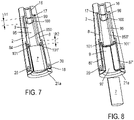
- La compréhension de cette description sera facilitée en se référant aux dessins joints, dans lesquels :
- La
figure 1 illustre une vue en perspective d'un tire-bouchon selon l'invention, - La
figure 2 illustre une vue en perspective de l'ensemble des pièces constitutives du tire-bouchon de lafigure 1 , - Les
figures 3 à 8 représentent des vues en coupe du tire-bouchon de lafigure 1 au cours des différentes étapes de son utilisation pour déboucher une bouteille. - Dans la variante de réalisation illustrée aux figures, le tire-bouchon 1 selon l'invention comporte un corps 2 d'allure générale tubulaire dont la paroi externe est pleine et qui peut être réalisé en un matériau tel que notamment du bois, un métal, un plastique, un matériau composite, ou tout autre matériau équivalent à la fois solide et esthétique. De manière classique, le corps 2 délimite intérieurement un logement 5 apte à abriter une vrille 3 destinée à être entraînée en rotation autour de l'axe longitudinal du corps 2 par un utilisateur manipulant un élément de préhension, tel qu'une poignée 4 émergeant du corps 2 et reliée à une extrémité de la vrille 3.
- Conformément à l'invention, le tire-bouchon 1 est par ailleurs équipé d'un dispositif d'éjection d'un bouchon 7 resté logé dans le logement 5 après son extraction d'une bouteille 11. Le dispositif d'éjection comporte un berceau 6, d'allure tubulaire. Tel que visible aux
figures 3 à 8 , le logement 5 et le berceau 6 présentent une forme complémentaire permettant leur emboîtement. Le berceau 6 est par ailleurs conformé en sorte d'être apte à accueillir la vrille 3 et un bouchon 7 vissé dans la vrille 3. Le berceau 6 peut être réalisé en un matériau tel que par exemple un plastique, un matériau composite, un matériau céramique, un métal ou tout autre matériau équivalent. - Dans la variante de réalisation illustrée, le berceau 6 est formé d'un manchon fixe 8 destiné à être solidarisé au corps 2 du tire-bouchon 1 et d'un manchon coulissant 9, mobile en translation par rapport au manchon fixe 8, entre une position dans laquelle il est entièrement emboîté et logé dans le manchon fixe 8 (cf. par exemple
fig. 5 ) et une position dans laquelle il est au moins partiellement extrait du manchon fixe 8 (cf.fig. 6 ). - Les manchons fixe 8 et coulissant 9 présentent une extrémité haute 80, 90 et une extrémité basse 81, 91 en considérant une position verticale du berceau 6. Ils présentent chacun un premier tronçon 82, 92, dont la section est prévue apte à accueillir, de manière serrée, un bouchon 7 vissé sur la vrille 3 et un second tronçon 83, 93, de section supérieure à celle du premier tronçon 82, 92 apte à être emboîté sur le goulot 10 d'un récipient fermé par le bouchon 7, tel qu'une bouteille 11. Chacun des manchons fixe 8 et coulissant 9 présente ainsi un épaulement 84, 94 formé entre son premier tronçon 82, 92 et son second tronçon 83, 93.
- Dans la variante de réalisation illustrée, la paroi périphérique du manchon fixe 8 comporte d'une part deux bandes de matière 85, 85', dont les faces externes sont incurvées tandis que les faces internes 850, 850' sont d'allure plane. Ces deux bandes de matière 85, 85' sont symétriques par rapport à l'axe du manchon fixe 8 et s'étendent sur son premier tronçon 82 entre son extrémité haute 80 et son épaulement 84. Leurs faces internes 850, 850' sont espacées d'une distance dl permettant le serrage d'un bouchon 7. Par ailleurs, les bandes de matière 85, 85' se prolongent sous l'épaulement 84 et définissent ainsi deux ailettes 101, 101' de hauteur h2 s'étendant au niveau de l'extrémité supérieure du second tronçon 83 du manchon fixe 8. Par ailleurs, les bandes de matière 85, 85' délimitent deux fentes longitudinales 86, 86' s'étendant également entre l'extrémité haute 80 et l'épaulement 84 du premier tronçon 82.
- La paroi périphérique du manchon fixe 8 comporte en outre deux bandes de matière 87, 87' symétriques par rapport à l'axe du manchon fixe 8 et s'étendant sur son second tronçon 83 entre son épaulement 84 et son extrémité basse 81, en délimitant deux fentes longitudinales 88, 88' (cf.
fig. 2 ). Les bandes de matière 87, 87' du second tronçon 83 du manchon fixe 8 présentent des faces internes incurvées, espacées d'un diamètre d2 et présentent une largeur 12 supérieure à la largeur 11 des bandes de matière 85, 85' du premier tronçon 82, et choisie de manière à conférer une largeur identique à l'ensemble des fentes longitudinales 86, 86', 88, 88' du manchon fixe 8. - Le manchon coulissant 9 présente une paroi périphérique complémentaire à celle du manche fixe 8. En effet, elle comporte sur chacun de ses premier et second tronçons 92, 93 deux bandes de matière 95, 95', 97, 97' s'étendant respectivement entre son extrémité haute 90 et l'épaulement 94, et entre ce dernier et son extrémité basse 91. Ces bandes de matière 95, 95', 97, 97' sont complémentaires aux fentes longitudinales 86, 86', 88, 88' du manchon fixe 8 et délimitent ainsi sur le manchon coulissant 9 des fentes longitudinales 96, 96', 98, 98' complémentaires aux bandes de matière 85, 85', 87, 87' du manchon fixe 8.
- Il est par ailleurs à noter que les bandes de matière 85, 85', 87, 87', 95, 95', 97, 97' comportent des chants longitudinaux rectilignes.
- Grâce à une telle structure, les deux manchons fixe 8 et coulissant 9 peuvent être emboités, leurs bandes de matière respectives 85, 85', 87, 87', 95, 95', 97, 97' venant s'insérer dans leurs fentes longitudinales respectives 86, 86', 88, 88', 96, 96', 98, 98' et se retrouvant par conséquent en contact les unes avec les autres au niveau de leurs chants longitudinaux rectilignes respectifs. Ces derniers définissent, comme il sera décrit plus en détail ci-dessous des premiers moyens de guidage en translation du manchon coulissant 9 par rapport au manchon fixe 8. Il est à noter que le manchon coulissant 9 est bloqué en rotation par rapport au manchon fixe 8 grâce au contact entre les chants longitudinaux respectifs des bandes de matière 85, 85', 87, 87', 95, 95', 97, 97' quelle que soit sa position par rapport au manchon fixe 8.
- Conformément à l'invention, l'extrémité haute 90 du manchon coulissant 9 est par ailleurs refermée par un opercule 99 présentant un orifice central 12 apte à permettre le passage de la vrille 3 lorsque le berceau 6 est emboîté dans le corps 2 du tire-bouchon 1.
- En référence à la
figure 2 , le bord de l'opercule 99 du manchon coulissant 9 comporte deux rainures 13 opposées, centrées dans le prolongement de chacune des fentes longitudinales 96, 96'. Elles sont prévues aptes à coopérer, lorsque les deux manchons 8, 9 sont emboîtés, avec deux nervures longitudinales opposées 14, centrées sur la face interne plane 850, 850' de chacune des bandes complémentaires 85, 85' de la paroi périphérique du premier tronçon 82 du manchon fixe 8, destinée à être reçue dans ladite fente 96, 96'. L'ensemble formé par les deux rainures 13 du manchon coulissant 9 et les deux nervures longitudinales 14 du manchon fixe 8 définit des seconds moyens de guidage en translation du manchon coulissant 9 par rapport au manchon fixe 8. - Il convient de noter que les nervures 14 permettent également d'assurer un blocage en rotation d'un bouchon 7, logé dans la partie du tire-bouchon 1 formée par les premiers tronçons 82, 92 des manchons fixe 8 et coulissant 9, après son extraction d'une bouteille 11, lors du dévissage de la vrille 3. Bien entendu, d'autres moyens de blocage en rotation du bouchon 7 peuvent être envisagés, tels que par exemple une paire de nervures formées sur la face interne de chacune des bandes de matières 95, 95' du manchon coulissant 9, ou tous autres moyens équivalents.
- D'autre part, l'opercule 99 comporte également deux pattes opposées 15, 15' s'étendant dans son plan, sur son bord, dans le prolongement des deux bandes de matières 95, 95' du premier tronçon 92 du manchon coulissant 9. Ces deux pattes 15, 15' prennent appui sur l'épaulement 84 du manchon fixe 8 lorsque le manchon coulissant 9 est amené vers sa position dans laquelle il est au moins partiellement extrait du manchon fixe 8, de sorte à interdire son extraction totale du manchon fixe 8. Par ailleurs, chacune des pattes 15, 15' présente deux bords latéraux opposés qui s'étendent en butée contre les chants longitudinaux des bandes de matière 85, 85' du manchon fixe 8 ce qui empêche également toute rotation du manchon coulissant 9 par rapport au manchon fixe 8. Enfin, la face inférieure de l'opercule 99 est prolongée par une butée tubulaire 100, centrée sur son orifice central 12, et présentant une hauteur h1 identique à la hauteur h2 des ailettes 101, 101'.
- Le manchon fixe 8 comporte par ailleurs un troisième tronçon 16 s'étendant dans le prolongement de son premier tronçon 82 et présentant un diamètre externe inférieur au diamètre externe du premier tronçon 82. Ainsi, le manchon fixe 8 comporte un second épaulement 17 s'étendant entre son premier tronçon 82 et son troisième tronçon 16.
- D'autre part, l'extrémité basse 81 du manchon fixe 8 comporte une collerette 18 sur laquelle s'étendent une pluralité de trous 19 régulièrement répartis et permettant la fixation du manchon fixe 8 au corps 2 du tire-bouchon 1 par exemple au moyen de vis 20 introduites dans les trous 19 et vissées dans le corps 2. Bien entendu, d'autres moyens de fixation équivalents peuvent être envisagés.
- L'extrémité basse 91 du manchon coulissant 9 est prolongée par une collerette 21 s'étendant en avant de la collerette 18 du manchon fixe 8 lorsque les deux manchons sont emboîtés. Cette collerette 21 assure la fonction de moyen de préhension permettant à un utilisateur de manipuler plus facilement le dispositif d'éjection selon l'invention. Dans la variante de réalisation illustrée, la collerette de préhension 21 comporte deux fentes transversales 22 la départageant en deux demi-collerettes 21a, 21b s'étendant dans le prolongement des bandes de matière 97, 97' du second tronçon 93 du manchon coulissant 9. Ceci permet le rapprochement de ces deux bandes de matière 97, 97' pour faciliter le coulissement du manchon coulissant 9 par rapport au manchon fixe 8, comme il sera expliqué ci-dessous.
- En pratique, et en référence aux
figures 3 à 8 , lors de l'utilisation du tire-bouchon 1 selon l'invention, équipé du dispositif d'éjection qui vient d'être décrit, pour déboucher une bouteille 11, l'utilisateur s'assure d'abord que le manchon coulissant 9 est totalement emboîté dans le manchon fixe 8 et qu'il est par conséquent effacé dans celui-ci. Il emboîte ensuite le tire-bouchon 1 sur le goulot 10 de la bouteille 11, obturé par le bouchon 7. L'ensemble formé par les seconds tronçons 83, 93 respectifs des manchons fixe 8 et coulissant 9 est alors placé autour du goulot 10 (cf.fig. 3 ). La vrille 3 est ensuite vissée dans le bouchon 7 et une force de traction exercée sur ce dernier permet de l'amener progressivement dans l'ensemble formé par les premiers tronçons 82, 92 respectifs des manchons fixe 8 et coulissant 9 jusqu'à ce qu'il soit stoppé par la butée annulaire 100 de l'opercule 99 du manchon coulissant 9 (cf.fig. 4 ). La distance dl comprise entre les faces internes planes 850, 850' des bandes de matière 85, 85'du premier tronçon 82 du manchon fixe étant choisie de manière à obtenir un ajustement serré du bouchon 7 reçu dans le berceau 6, ledit bouchon 7 reste dans l'état comprimé dans lequel il se trouvait alors qu'il était logé dans la bouteille 11. Celle-ci étant maintenant débouchée, l'utilisateur retire le tire-bouchon 1 du goulot 10, le bouchon 7 demeurant vissé sur la vrille 3 et bloqué dans le corps 2 du tire-bouchon 1. - Afin de permettre une nouvelle utilisation du tire-bouchon 1, et par conséquent libérer le bouchon 7 bloqué dans le berceau 6, l'utilisateur dévisse la vrille 3 (cf.
fig. 5 ). Il saisit ensuite les deux demi-collerettes 21a, 21b bordant l'extrémité basse 91 du manchon coulissant 9. Ceci a pour conséquence de provoquer le resserrement des bandes de matière 97, 97' du manchon coulissant 9, et de faciliter le coulissement de ce dernier par rapport au manchon fixe 8. Le manchon coulissant 9, guidé en translation par les premiers et seconds moyens de guidage en translation décrits ci-dessus, est progressivement extrait du corps 2 du tire-bouchon 1. Lors de son déplacement, le manchon coulissant 9 entraîne avec lui le bouchon 7 sur lequel la butée tubulaire 100 de l'opercule 99 exerce une force F1 orientée en direction de l'extrémité basse 80 du manchon fixe 8. Lorsque les pattes 15 de l'opercule 99 arrivent en butée sur l'épaulement 84 du manchon fixe 8, le premier tronçon 92 du manchon coulissant 9, contenant toujours le bouchon 7, est logé à l'intérieur du second tronçon 83 du manchon fixe 8 (cf.fig. 6 ). Le bouchon 7 n'est alors plus contraint entre les bandes de matière 85, 85', 95, 95' des manchons fixe 8 et coulissant 9 et peut au moins partiellement se dilater entre les bandes de matière 95, 95' du manchon coulissant 9, et les bandes de matière 87, 87' du manchon fixe 8. Grâce à la présence de la butée tubulaire 100 présentant une hauteur h1 équivalente à celle h2 des ailettes 101, 101', la face supérieure du bouchon 7 se retrouve située juste sous l'extrémité inférieure desdites ailettes 101, 101'. Puis, du fait de sa dilation au moins partielle, le bord de la face supérieure du bouchon 7 se retrouve en butée contre l'extrémité inférieure des ailettes 101, 101' du manchon fixe 8. Par conséquent, lorsque l'utilisateur repousse le manchon coulissant 9 de manière à le ré-emboîter dans le manchon fixe 8, le bouchon 7 n'est plus entraîné avec lui mais demeure dans l'ensemble formé par les seconds tronçons respectifs 83, 93 des manchons fixe 8 et coulissant 9, retenu par les ailettes 101, 101' (cf.fig. 7 ). Le diamètre interne d2 de cet ensemble étant supérieur à celui du bouchon 7, ce dernier tombe maintenant par gravité et peut être aisément récupéré par l'utilisateur (cf.fig. 8 ). - Il est à noter que le dispositif d'éjection selon l'invention peut être conçu en tant que module universel adapté pour s'adapter à un grand nombre de tire-bouchons présentant différentes formes et caractéristiques.
Claims (15)
- Dispositif d'éjection d'un bouchon (7) hors d'un tire-bouchon (1) du type comportant un corps (2) présentant un passage traversant d'allure tubulaire définissant un logement (5) dans lequel est reçue une vrille (3) apte à être entraînée en rotation autour de l'axe longitudinal dudit corps au moyen d'un élément de préhension (4) relié à l'une de ses extrémités et s'étendant à l'extérieur dudit corps (2), ledit dispositif comportant un berceau (6) d'allure tubulaire apte à être hébergé dans le logement (5) du tire-bouchon et à accueillir ladite vrille (3) et un bouchon (7) vissé dans la vrille (3), caractérisé en ce que ledit berceau (6) est formé d'un manchon fixe (8) destiné à être solidarisé audit corps (2) du tire-bouchon (1) et d'un manchon coulissant (9), mobile en translation par rapport au manchon fixe (8), entre une position dans laquelle il est entièrement emboîté dans le manchon fixe (8) et une position dans laquelle il est au moins partiellement extrait dudit manchon fixe (8), lesdits manchons fixe (8) et coulissant (9) présentant une extrémité haute (80, 90) et une extrémité basse (81, 91) en considérant une position verticale du dispositif d'éjection, et ledit manchon coulissant (9) comportant des moyens aptes à exercer, sur un bouchon (7) retenu dans ledit tire-bouchon (1), une force (F1) orientée en direction de l'extrémité basse (81) du manchon fixe (8), lorsqu'il est amené vers sa position dans laquelle il est au moins partiellement extrait dudit manchon fixe (8).
- Dispositif d'éjection selon la revendication 1, caractérisé en ce que l'extrémité haute (90) du manchon coulissant (9) est refermée par un opercule (99) présentant un orifice central (12) apte à permettre le passage de la vrille (3).
- Dispositif d'éjection selon l'une quelconque des revendications 1 ou 2, caractérisé en ce que lesdits manchons fixe (8) et coulissant (9) comportent des moyens de blocage en rotation du manchon coulissant (9).
- Dispositif d'éjection selon l'une quelconque des revendications précédentes, caractérisé en ce que chacun desdits manchons fixe (8) et coulissant (9) comporte un premier tronçon (82, 92), apte à accueillir un bouchon (7) vissé sur la vrille (3) et un second tronçon (83, 93), apte à être emboîté sur le goulot (10) d'une bouteille (11), chacun des manchons fixe (8) et coulissant (9) présentant un épaulement (84, 94) formé entre son premier et son second tronçon (82, 92, 83, 93).
- Dispositif d'éjection selon la revendication 4, caractérisé en ce que la paroi périphérique de chacun des manchons fixe (8) et coulissant (9) comporte au moins une fente longitudinale (86, 86', 88, 88', 96, 96', 98, 98') s'étendant respectivement sur son premier tronçon (82, 92) entre son extrémité haute (80, 90) et son épaulement (84, 94) et sur son second tronçon (83, 93) entre son épaulement (84, 94) et son extrémité basse (81, 91), et dans laquelle est reçue une bande de matière complémentaire (85, 85', 95, 95', 87, 87', 97, 97') de la paroi périphérique du premier et du second tronçon (83, 92, 83, 93) de l'autre manchon.
- Dispositif d'éjection selon la revendication 5, caractérisé en ce qu'il comporte au moins une rainure (13) et une nervure (14) longitudinales complémentaires s'étendant respectivement sur le bord de l'opercule (99) du manchon coulissant (9) dans le prolongement de la fente (96, 96') que comporte ce dernier, et sur la face interne (850, 850') de la bande complémentaire (85, 85') de la paroi périphérique du premier tronçon (82) du manchon fixe (8) destinée à être reçue dans ladite fente (96, 96'), ou inversement.
- Dispositif d'éjection selon l'une quelconque des revendications 4 à 6, caractérisé en ce que le manchon coulissant (9) comporte au moins une patte (15) prolongeant le bord externe de l'opercule (99) dans le prolongement de sa paroi périphérique (95, 95') ladite patte (15) étant apte à prendre appui sur l'épaulement (84) formé entre le premier tronçon (82) et le second tronçon (83) du manchon fixe (8) lorsque le manchon coulissant (9) est amené vers sa position dans laquelle il est au moins partiellement extrait dudit corps (2).
- Dispositif d'éjection selon l'une quelconque des revendications précédentes, caractérisé en ce que le manchon coulissant (9) comporte des moyens de préhension aptes à permettre sa manœuvre par un utilisateur.
- Dispositif d'éjection selon la revendication 8, caractérisé en ce que l'extrémité basse (91) du manchon coulissant (9) est prolongée par une collerette (21) de préhension.
- Dispositif d'éjection selon la revendication 9, caractérisé en ce que ladite collerette (21) de préhension comporte au moins une fente transversale (22) s'étendant dans le prolongement de la fente (98, 98') que comporte la paroi périphérique du manchon coulissant (9).
- Dispositif d'éjection selon l'une quelconque des revendications précédentes, caractérisé en ce que l'extrémité basse (81) du manchon fixe (8) comporte une collerette (18) apte à permettre sa fixation au corps (2) d'un tire-bouchon (1) par des moyens d'assemblage appropriés.
- Dispositif d'éjection selon l'une quelconque des revendications 2 à 11, caractérisé en ce que l'opercule (99) du manchon coulissant (9) comporte une butée annulaire (100) de hauteur h1 centrée sur son orifice central (12) et s'étendant sous sa face inférieure.
- Dispositif d'éjection selon la revendication 12, caractérisé en ce que le manchon fixe (8) comporte au moins une ailette (101, 101') de hauteur h2 égale à celle de la butée annulaire (100) du manchon coulissant (9).
- Tire-bouchon (1) comportant un corps (2) creux ménageant un logement (5) dans lequel est reçue une vrille (3) apte à être entraînée en rotation autour de l'axe longitudinal dudit corps (2) au moyen d'un élément de préhension (4) relié à l'une de ses extrémités et s'étendant à l'extérieur dudit corps (2), ledit logement (5) étant apte à accueillir un bouchon (7) vissé sur la vrille (3) et présentant, au voisinage de l'extrémité libre de la vrille (3), au moins une portion de section circulaire apte à être emboîtée sur le goulot (10) d'une bouteille (11), caractérisé en ce qu'il comporte un dispositif d'éjection d'un bouchon (7) selon l'une quelconque des revendications précédentes.
- Tire-bouchon (1) selon la revendication 14, caractérisé en ce que le logement (5) présente une forme complémentaire à celle du berceau (6) que comporte ledit dispositif d'éjection.
Applications Claiming Priority (2)
| Application Number | Priority Date | Filing Date | Title |
|---|---|---|---|
| FR1561148A FR3043999B1 (fr) | 2015-11-19 | 2015-11-19 | Dispositif d'ejection d'un bouchon hors d'un tire-bouchon et tire-bouchon equipe d'un tel dispositif d'ejection |
| PCT/FR2016/052803 WO2017085370A1 (fr) | 2015-11-19 | 2016-10-27 | Dispositif d'éjection d'un bouchon hors d'un tire-bouchon et tire-bouchon équipé d'un tel dispositif d'éjection |
Publications (2)
| Publication Number | Publication Date |
|---|---|
| EP3377437A1 EP3377437A1 (fr) | 2018-09-26 |
| EP3377437B1 true EP3377437B1 (fr) | 2022-05-18 |
Family
ID=55182387
Family Applications (1)
| Application Number | Title | Priority Date | Filing Date |
|---|---|---|---|
| EP16809943.0A Active EP3377437B1 (fr) | 2015-11-19 | 2016-10-27 | Dispositif d'éjection d'un bouchon hors d'un tire-bouchon et tire-bouchon équipé d'un tel dispositif d'éjection |
Country Status (6)
| Country | Link |
|---|---|
| US (1) | US10696528B2 (fr) |
| EP (1) | EP3377437B1 (fr) |
| CA (1) | CA3005415A1 (fr) |
| ES (1) | ES2924424T3 (fr) |
| FR (1) | FR3043999B1 (fr) |
| WO (1) | WO2017085370A1 (fr) |
Families Citing this family (3)
| Publication number | Priority date | Publication date | Assignee | Title |
|---|---|---|---|---|
| CN206337006U (zh) * | 2017-01-06 | 2017-07-18 | 金丰国际有限公司 | 复合式开瓶器 |
| USD864684S1 (en) * | 2017-09-06 | 2019-10-29 | Psp | Corkscrew |
| USD865464S1 (en) * | 2017-09-06 | 2019-11-05 | Psp | Corkscrew |
Family Cites Families (10)
| Publication number | Priority date | Publication date | Assignee | Title |
|---|---|---|---|---|
| GB191326676A (en) * | 1913-11-20 | 1914-01-15 | Adolf Fister | Improvements in and relating to Cork-screws. |
| DE3346414C1 (de) * | 1983-12-22 | 1985-01-31 | August Reutershan Gmbh & Co Kg, 5650 Solingen | Mit einer Glocke versehener Korkzieher |
| AT380222B (de) * | 1984-06-01 | 1986-04-25 | Philips Nv | Korkenzieher |
| US5012703A (en) * | 1990-02-05 | 1991-05-07 | Helmut Reinbacher | Cork removal apparatus |
| US5079975A (en) * | 1991-06-27 | 1992-01-14 | Spencer Jr Frank W | Automatic corkscrew |
| US7069825B2 (en) * | 2004-11-26 | 2006-07-04 | Technical Development (Hk) Limited | Corkscrew |
| US7231850B2 (en) * | 2005-11-08 | 2007-06-19 | Ching-Chen Wang | Manual wine bottle opener |
| CN101081684B (zh) * | 2007-07-18 | 2011-11-30 | 曾超 | 开瓶器 |
| CN201214621Y (zh) * | 2008-04-18 | 2009-04-01 | 唐念东 | 一种开瓶器 |
| GB201311139D0 (en) * | 2013-06-22 | 2013-08-07 | Kalogroulis Alexander J | Wine opener |
-
2015
- 2015-11-19 FR FR1561148A patent/FR3043999B1/fr not_active Expired - Fee Related
-
2016
- 2016-10-27 US US15/776,869 patent/US10696528B2/en active Active
- 2016-10-27 EP EP16809943.0A patent/EP3377437B1/fr active Active
- 2016-10-27 ES ES16809943T patent/ES2924424T3/es active Active
- 2016-10-27 CA CA3005415A patent/CA3005415A1/fr not_active Abandoned
- 2016-10-27 WO PCT/FR2016/052803 patent/WO2017085370A1/fr not_active Ceased
Also Published As
| Publication number | Publication date |
|---|---|
| CA3005415A1 (fr) | 2017-05-26 |
| EP3377437A1 (fr) | 2018-09-26 |
| FR3043999B1 (fr) | 2017-12-01 |
| WO2017085370A1 (fr) | 2017-05-26 |
| US20180327241A1 (en) | 2018-11-15 |
| ES2924424T3 (es) | 2022-10-06 |
| FR3043999A1 (fr) | 2017-05-26 |
| US10696528B2 (en) | 2020-06-30 |
Similar Documents
| Publication | Publication Date | Title |
|---|---|---|
| FR2579969A1 (fr) | ||
| WO2019030451A2 (fr) | Dispositif de conditionnement d'objet, ensemble et procede d'extraction correspondant | |
| EP2043452B1 (fr) | Porte-sucette sécurisé | |
| EP3315457B1 (fr) | Tire-bouchon à double levier | |
| EP3383791B1 (fr) | Tire-bouchon à levier | |
| WO2017085370A1 (fr) | Dispositif d'éjection d'un bouchon hors d'un tire-bouchon et tire-bouchon équipé d'un tel dispositif d'éjection | |
| EP0227510B1 (fr) | Dispositif de sécurité pour vaporisateur | |
| EP3235754B1 (fr) | Ensemble pour la fermeture d'un tube et tube muni d'un tel ensemble | |
| WO2020229770A1 (fr) | Dispositif pour le maintien et la libération d'un objet et procédés correspondants | |
| EP0027780A1 (fr) | Bouteille | |
| EP1678052B1 (fr) | Ensemble de distribution de produit fluide | |
| FR2988702A1 (fr) | Bouchon de fermeture du goulot d'un contenant | |
| EP0885764A1 (fr) | Bouchon de réservoir de carburant pour véhicule. | |
| FR2780390A1 (fr) | Tire-bouchon de type automatique | |
| WO2017077244A1 (fr) | Dispositif de conditionnement pour un produit à distribuer, notamment pour un parfum | |
| WO2007034076A1 (fr) | Dispositif de bouchage d'un col de recipient, recipient equipe d'un tel dispositif et procede de fabrication d'un tel dispositif | |
| EP2739543B1 (fr) | Dispositif pour obturer le goulot d'une bouteille | |
| CA3132926C (fr) | Dispositif pour le maintien et la liberation d'un objet et procedes correspondants | |
| WO2012022923A1 (fr) | Dispositif pour deboucher des bouteilles a bouchon comportant une section de prehension | |
| FR3080109A1 (fr) | Dispositif decapsuleur - recapsuleur | |
| FR2933385A1 (fr) | Bouchon a ouverture unique | |
| CA3132926A1 (fr) | Dispositif pour le maintien et la liberation d'un objet et procedes correspondants | |
| FR3066680B1 (fr) | Tete de distribution de produit cosmetique, dispositif et procede associes | |
| BE554545A (fr) | Bouchon en plusieurs parties pour récipients de tout genre | |
| FR3134297A1 (fr) | Réceptacle pour un produit cosmétique ; recharge, flaconnette et capot pour un tel réceptacle. |
Legal Events
| Date | Code | Title | Description |
|---|---|---|---|
| STAA | Information on the status of an ep patent application or granted ep patent |
Free format text: STATUS: UNKNOWN |
|
| STAA | Information on the status of an ep patent application or granted ep patent |
Free format text: STATUS: THE INTERNATIONAL PUBLICATION HAS BEEN MADE |
|
| PUAI | Public reference made under article 153(3) epc to a published international application that has entered the european phase |
Free format text: ORIGINAL CODE: 0009012 |
|
| STAA | Information on the status of an ep patent application or granted ep patent |
Free format text: STATUS: REQUEST FOR EXAMINATION WAS MADE |
|
| 17P | Request for examination filed |
Effective date: 20180418 |
|
| AK | Designated contracting states |
Kind code of ref document: A1 Designated state(s): AL AT BE BG CH CY CZ DE DK EE ES FI FR GB GR HR HU IE IS IT LI LT LU LV MC MK MT NL NO PL PT RO RS SE SI SK SM TR |
|
| AX | Request for extension of the european patent |
Extension state: BA ME |
|
| DAV | Request for validation of the european patent (deleted) | ||
| DAX | Request for extension of the european patent (deleted) | ||
| GRAP | Despatch of communication of intention to grant a patent |
Free format text: ORIGINAL CODE: EPIDOSNIGR1 |
|
| STAA | Information on the status of an ep patent application or granted ep patent |
Free format text: STATUS: GRANT OF PATENT IS INTENDED |
|
| INTG | Intention to grant announced |
Effective date: 20220114 |
|
| GRAS | Grant fee paid |
Free format text: ORIGINAL CODE: EPIDOSNIGR3 |
|
| GRAA | (expected) grant |
Free format text: ORIGINAL CODE: 0009210 |
|
| STAA | Information on the status of an ep patent application or granted ep patent |
Free format text: STATUS: THE PATENT HAS BEEN GRANTED |
|
| AK | Designated contracting states |
Kind code of ref document: B1 Designated state(s): AL AT BE BG CH CY CZ DE DK EE ES FI FR GB GR HR HU IE IS IT LI LT LU LV MC MK MT NL NO PL PT RO RS SE SI SK SM TR |
|
| REG | Reference to a national code |
Ref country code: GB Ref legal event code: FG4D Free format text: NOT ENGLISH |
|
| REG | Reference to a national code |
Ref country code: CH Ref legal event code: EP |
|
| REG | Reference to a national code |
Ref country code: IE Ref legal event code: FG4D Free format text: LANGUAGE OF EP DOCUMENT: FRENCH |
|
| REG | Reference to a national code |
Ref country code: DE Ref legal event code: R096 Ref document number: 602016072272 Country of ref document: DE |
|
| REG | Reference to a national code |
Ref country code: AT Ref legal event code: REF Ref document number: 1493056 Country of ref document: AT Kind code of ref document: T Effective date: 20220615 |
|
| REG | Reference to a national code |
Ref country code: NL Ref legal event code: FP |
|
| REG | Reference to a national code |
Ref country code: LT Ref legal event code: MG9D |
|
| REG | Reference to a national code |
Ref country code: ES Ref legal event code: FG2A Ref document number: 2924424 Country of ref document: ES Kind code of ref document: T3 Effective date: 20221006 |
|
| REG | Reference to a national code |
Ref country code: AT Ref legal event code: MK05 Ref document number: 1493056 Country of ref document: AT Kind code of ref document: T Effective date: 20220518 |
|
| PG25 | Lapsed in a contracting state [announced via postgrant information from national office to epo] |
Ref country code: SE Free format text: LAPSE BECAUSE OF FAILURE TO SUBMIT A TRANSLATION OF THE DESCRIPTION OR TO PAY THE FEE WITHIN THE PRESCRIBED TIME-LIMIT Effective date: 20220518 Ref country code: PT Free format text: LAPSE BECAUSE OF FAILURE TO SUBMIT A TRANSLATION OF THE DESCRIPTION OR TO PAY THE FEE WITHIN THE PRESCRIBED TIME-LIMIT Effective date: 20220919 Ref country code: NO Free format text: LAPSE BECAUSE OF FAILURE TO SUBMIT A TRANSLATION OF THE DESCRIPTION OR TO PAY THE FEE WITHIN THE PRESCRIBED TIME-LIMIT Effective date: 20220818 Ref country code: LT Free format text: LAPSE BECAUSE OF FAILURE TO SUBMIT A TRANSLATION OF THE DESCRIPTION OR TO PAY THE FEE WITHIN THE PRESCRIBED TIME-LIMIT Effective date: 20220518 Ref country code: HR Free format text: LAPSE BECAUSE OF FAILURE TO SUBMIT A TRANSLATION OF THE DESCRIPTION OR TO PAY THE FEE WITHIN THE PRESCRIBED TIME-LIMIT Effective date: 20220518 Ref country code: GR Free format text: LAPSE BECAUSE OF FAILURE TO SUBMIT A TRANSLATION OF THE DESCRIPTION OR TO PAY THE FEE WITHIN THE PRESCRIBED TIME-LIMIT Effective date: 20220819 Ref country code: FI Free format text: LAPSE BECAUSE OF FAILURE TO SUBMIT A TRANSLATION OF THE DESCRIPTION OR TO PAY THE FEE WITHIN THE PRESCRIBED TIME-LIMIT Effective date: 20220518 Ref country code: BG Free format text: LAPSE BECAUSE OF FAILURE TO SUBMIT A TRANSLATION OF THE DESCRIPTION OR TO PAY THE FEE WITHIN THE PRESCRIBED TIME-LIMIT Effective date: 20220818 Ref country code: AT Free format text: LAPSE BECAUSE OF FAILURE TO SUBMIT A TRANSLATION OF THE DESCRIPTION OR TO PAY THE FEE WITHIN THE PRESCRIBED TIME-LIMIT Effective date: 20220518 |
|
| PG25 | Lapsed in a contracting state [announced via postgrant information from national office to epo] |
Ref country code: RS Free format text: LAPSE BECAUSE OF FAILURE TO SUBMIT A TRANSLATION OF THE DESCRIPTION OR TO PAY THE FEE WITHIN THE PRESCRIBED TIME-LIMIT Effective date: 20220518 Ref country code: PL Free format text: LAPSE BECAUSE OF FAILURE TO SUBMIT A TRANSLATION OF THE DESCRIPTION OR TO PAY THE FEE WITHIN THE PRESCRIBED TIME-LIMIT Effective date: 20220518 Ref country code: LV Free format text: LAPSE BECAUSE OF FAILURE TO SUBMIT A TRANSLATION OF THE DESCRIPTION OR TO PAY THE FEE WITHIN THE PRESCRIBED TIME-LIMIT Effective date: 20220518 Ref country code: IS Free format text: LAPSE BECAUSE OF FAILURE TO SUBMIT A TRANSLATION OF THE DESCRIPTION OR TO PAY THE FEE WITHIN THE PRESCRIBED TIME-LIMIT Effective date: 20220918 |
|
| PG25 | Lapsed in a contracting state [announced via postgrant information from national office to epo] |
Ref country code: SM Free format text: LAPSE BECAUSE OF FAILURE TO SUBMIT A TRANSLATION OF THE DESCRIPTION OR TO PAY THE FEE WITHIN THE PRESCRIBED TIME-LIMIT Effective date: 20220518 Ref country code: SK Free format text: LAPSE BECAUSE OF FAILURE TO SUBMIT A TRANSLATION OF THE DESCRIPTION OR TO PAY THE FEE WITHIN THE PRESCRIBED TIME-LIMIT Effective date: 20220518 Ref country code: RO Free format text: LAPSE BECAUSE OF FAILURE TO SUBMIT A TRANSLATION OF THE DESCRIPTION OR TO PAY THE FEE WITHIN THE PRESCRIBED TIME-LIMIT Effective date: 20220518 Ref country code: EE Free format text: LAPSE BECAUSE OF FAILURE TO SUBMIT A TRANSLATION OF THE DESCRIPTION OR TO PAY THE FEE WITHIN THE PRESCRIBED TIME-LIMIT Effective date: 20220518 Ref country code: DK Free format text: LAPSE BECAUSE OF FAILURE TO SUBMIT A TRANSLATION OF THE DESCRIPTION OR TO PAY THE FEE WITHIN THE PRESCRIBED TIME-LIMIT Effective date: 20220518 Ref country code: CZ Free format text: LAPSE BECAUSE OF FAILURE TO SUBMIT A TRANSLATION OF THE DESCRIPTION OR TO PAY THE FEE WITHIN THE PRESCRIBED TIME-LIMIT Effective date: 20220518 |
|
| PGFP | Annual fee paid to national office [announced via postgrant information from national office to epo] |
Ref country code: IT Payment date: 20221028 Year of fee payment: 7 Ref country code: GB Payment date: 20221028 Year of fee payment: 7 Ref country code: ES Payment date: 20221130 Year of fee payment: 7 Ref country code: DE Payment date: 20221109 Year of fee payment: 7 |
|
| REG | Reference to a national code |
Ref country code: DE Ref legal event code: R097 Ref document number: 602016072272 Country of ref document: DE |
|
| PGFP | Annual fee paid to national office [announced via postgrant information from national office to epo] |
Ref country code: CH Payment date: 20221103 Year of fee payment: 7 |
|
| PLBE | No opposition filed within time limit |
Free format text: ORIGINAL CODE: 0009261 |
|
| STAA | Information on the status of an ep patent application or granted ep patent |
Free format text: STATUS: NO OPPOSITION FILED WITHIN TIME LIMIT |
|
| PG25 | Lapsed in a contracting state [announced via postgrant information from national office to epo] |
Ref country code: AL Free format text: LAPSE BECAUSE OF FAILURE TO SUBMIT A TRANSLATION OF THE DESCRIPTION OR TO PAY THE FEE WITHIN THE PRESCRIBED TIME-LIMIT Effective date: 20220518 |
|
| 26N | No opposition filed |
Effective date: 20230221 |
|
| PG25 | Lapsed in a contracting state [announced via postgrant information from national office to epo] |
Ref country code: SI Free format text: LAPSE BECAUSE OF FAILURE TO SUBMIT A TRANSLATION OF THE DESCRIPTION OR TO PAY THE FEE WITHIN THE PRESCRIBED TIME-LIMIT Effective date: 20220518 Ref country code: MC Free format text: LAPSE BECAUSE OF FAILURE TO SUBMIT A TRANSLATION OF THE DESCRIPTION OR TO PAY THE FEE WITHIN THE PRESCRIBED TIME-LIMIT Effective date: 20220518 |
|
| PG25 | Lapsed in a contracting state [announced via postgrant information from national office to epo] |
Ref country code: LU Free format text: LAPSE BECAUSE OF NON-PAYMENT OF DUE FEES Effective date: 20221027 |
|
| PG25 | Lapsed in a contracting state [announced via postgrant information from national office to epo] |
Ref country code: IE Free format text: LAPSE BECAUSE OF NON-PAYMENT OF DUE FEES Effective date: 20221027 |
|
| PG25 | Lapsed in a contracting state [announced via postgrant information from national office to epo] |
Ref country code: HU Free format text: LAPSE BECAUSE OF FAILURE TO SUBMIT A TRANSLATION OF THE DESCRIPTION OR TO PAY THE FEE WITHIN THE PRESCRIBED TIME-LIMIT; INVALID AB INITIO Effective date: 20161027 |
|
| PG25 | Lapsed in a contracting state [announced via postgrant information from national office to epo] |
Ref country code: CY Free format text: LAPSE BECAUSE OF FAILURE TO SUBMIT A TRANSLATION OF THE DESCRIPTION OR TO PAY THE FEE WITHIN THE PRESCRIBED TIME-LIMIT Effective date: 20220511 |
|
| REG | Reference to a national code |
Ref country code: DE Ref legal event code: R119 Ref document number: 602016072272 Country of ref document: DE |
|
| PG25 | Lapsed in a contracting state [announced via postgrant information from national office to epo] |
Ref country code: MK Free format text: LAPSE BECAUSE OF FAILURE TO SUBMIT A TRANSLATION OF THE DESCRIPTION OR TO PAY THE FEE WITHIN THE PRESCRIBED TIME-LIMIT Effective date: 20220511 |
|
| REG | Reference to a national code |
Ref country code: CH Ref legal event code: PL |
|
| GBPC | Gb: european patent ceased through non-payment of renewal fee |
Effective date: 20231027 |
|
| PG25 | Lapsed in a contracting state [announced via postgrant information from national office to epo] |
Ref country code: TR Free format text: LAPSE BECAUSE OF FAILURE TO SUBMIT A TRANSLATION OF THE DESCRIPTION OR TO PAY THE FEE WITHIN THE PRESCRIBED TIME-LIMIT Effective date: 20220511 |
|
| PG25 | Lapsed in a contracting state [announced via postgrant information from national office to epo] |
Ref country code: GB Free format text: LAPSE BECAUSE OF NON-PAYMENT OF DUE FEES Effective date: 20231027 |
|
| PG25 | Lapsed in a contracting state [announced via postgrant information from national office to epo] |
Ref country code: CH Free format text: LAPSE BECAUSE OF NON-PAYMENT OF DUE FEES Effective date: 20231031 |
|
| PG25 | Lapsed in a contracting state [announced via postgrant information from national office to epo] |
Ref country code: GB Free format text: LAPSE BECAUSE OF NON-PAYMENT OF DUE FEES Effective date: 20231027 Ref country code: DE Free format text: LAPSE BECAUSE OF NON-PAYMENT OF DUE FEES Effective date: 20240501 Ref country code: CH Free format text: LAPSE BECAUSE OF NON-PAYMENT OF DUE FEES Effective date: 20231031 |
|
| PG25 | Lapsed in a contracting state [announced via postgrant information from national office to epo] |
Ref country code: MT Free format text: LAPSE BECAUSE OF FAILURE TO SUBMIT A TRANSLATION OF THE DESCRIPTION OR TO PAY THE FEE WITHIN THE PRESCRIBED TIME-LIMIT Effective date: 20220511 |
|
| PG25 | Lapsed in a contracting state [announced via postgrant information from national office to epo] |
Ref country code: BG Free format text: LAPSE BECAUSE OF FAILURE TO SUBMIT A TRANSLATION OF THE DESCRIPTION OR TO PAY THE FEE WITHIN THE PRESCRIBED TIME-LIMIT Effective date: 20220518 |
|
| PGFP | Annual fee paid to national office [announced via postgrant information from national office to epo] |
Ref country code: NL Payment date: 20241031 Year of fee payment: 9 |
|
| PG25 | Lapsed in a contracting state [announced via postgrant information from national office to epo] |
Ref country code: BG Free format text: LAPSE BECAUSE OF FAILURE TO SUBMIT A TRANSLATION OF THE DESCRIPTION OR TO PAY THE FEE WITHIN THE PRESCRIBED TIME-LIMIT Effective date: 20220518 |
|
| PG25 | Lapsed in a contracting state [announced via postgrant information from national office to epo] |
Ref country code: IT Free format text: LAPSE BECAUSE OF NON-PAYMENT OF DUE FEES Effective date: 20231027 |
|
| REG | Reference to a national code |
Ref country code: ES Ref legal event code: FD2A Effective date: 20241209 |
|
| PG25 | Lapsed in a contracting state [announced via postgrant information from national office to epo] |
Ref country code: IT Free format text: LAPSE BECAUSE OF NON-PAYMENT OF DUE FEES Effective date: 20231027 |
|
| PGFP | Annual fee paid to national office [announced via postgrant information from national office to epo] |
Ref country code: BE Payment date: 20241031 Year of fee payment: 9 |
|
| PG25 | Lapsed in a contracting state [announced via postgrant information from national office to epo] |
Ref country code: ES Free format text: LAPSE BECAUSE OF NON-PAYMENT OF DUE FEES Effective date: 20231028 |
|
| PG25 | Lapsed in a contracting state [announced via postgrant information from national office to epo] |
Ref country code: ES Free format text: LAPSE BECAUSE OF NON-PAYMENT OF DUE FEES Effective date: 20231028 |
|
| PGFP | Annual fee paid to national office [announced via postgrant information from national office to epo] |
Ref country code: FR Payment date: 20250828 Year of fee payment: 10 |