EP3377689B1 - Gerät zum dampfbügeln mit aufhänger zum glätten von kleidungsstücken - Google Patents
Gerät zum dampfbügeln mit aufhänger zum glätten von kleidungsstücken Download PDFInfo
- Publication number
- EP3377689B1 EP3377689B1 EP16809989.3A EP16809989A EP3377689B1 EP 3377689 B1 EP3377689 B1 EP 3377689B1 EP 16809989 A EP16809989 A EP 16809989A EP 3377689 B1 EP3377689 B1 EP 3377689B1
- Authority
- EP
- European Patent Office
- Prior art keywords
- hanger
- control lever
- rod
- coat hanger
- appliance according
- Prior art date
- Legal status (The legal status is an assumption and is not a legal conclusion. Google has not performed a legal analysis and makes no representation as to the accuracy of the status listed.)
- Active
Links
Images


Classifications
-
- D—TEXTILES; PAPER
- D06—TREATMENT OF TEXTILES OR THE LIKE; LAUNDERING; FLEXIBLE MATERIALS NOT OTHERWISE PROVIDED FOR
- D06F—LAUNDERING, DRYING, IRONING, PRESSING OR FOLDING TEXTILE ARTICLES
- D06F73/00—Apparatus for smoothing or removing creases from garments or other textile articles by formers, cores, stretchers, or internal frames, with the application of heat or steam
-
- D—TEXTILES; PAPER
- D06—TREATMENT OF TEXTILES OR THE LIKE; LAUNDERING; FLEXIBLE MATERIALS NOT OTHERWISE PROVIDED FOR
- D06F—LAUNDERING, DRYING, IRONING, PRESSING OR FOLDING TEXTILE ARTICLES
- D06F87/00—Apparatus for moistening or otherwise conditioning the article to be ironed or pressed
Definitions
- the present invention relates to a steam ironing apparatus comprising a base enclosing a device for the production of a steam flow connected by a duct to a smoothing accessory comprising at least one hole for the emission of steam and relates more particularly to an apparatus in which the base comprises a hanger on which the garment to be smoothed can be placed when using the anti-crease accessory, the hanger being mounted to pivot on the base and being able to be immobilized in rotation by means a locking device.
- a steam ironing appliance comprising a steam generating base comprising a mast equipped with a hanger at its upper end, the hanger being mounted to rotate around the longitudinal axis of the mast and comprising a locking device making it possible to immobilize the hanger in different predetermined angular positions.
- Such an ironing device provided with a rotating hanger has the advantage of making the garment smoothing operation more ergonomic by allowing the user to rotate the garment around the mast and then to immobilize it in different angular positions.
- the hanger locking device disclosed in this document has the drawback of only allowing the hanger to be immobilized in a limited number of predetermined positions.
- the locking device disclosed in this document has the disadvantage of ensuring insufficient immobilization of the hanger in rotation when the spring used in the device. blocking is weakly rigid, and to be difficult to assemble when the spring used is sufficiently rigid to ensure good immobilization of the hanger.
- the locking device described in this document uses a spring-mounted pawl system which has the drawback of being relatively noisy when the position of the hanger is manually modified by the user.
- an aim of the present invention is to provide an ironing appliance remedying these drawbacks and which is simple and economical to produce.
- the invention relates to a steam ironing apparatus comprising a base enclosing a device for the production of a flow of steam connected by a duct to an anti-crease accessory comprising at least one hole for the emission.
- the base comprising a hanger on which the garment to be smoothed can be placed when using the steamer accessory, the hanger being mounted to pivot on the base about an axis by means of a pivot connection and capable of being immobilized in rotation by means of a locking device, characterized in that the locking device comprises a control member which can be moved manually by the user from an unlocked position, allowing free rotation of the hanger, towards a locked position in which the hanger is immobilized in rotation, and in that the movement of the control member from the unlocked position to the locked position causes the movement and / or the deformation of a braking from an initial position, allowing free rotation of the pivot linkage, to a braked position in which the braking element is held under pressure against an element to prevent rotation of the hanger and allows
- Such a device provided with a locking device provided with a friction braking element has the advantage of being simple and economical to implement and ensuring the immobilization of the hanger by the only friction forces generated by the pressure exerted by the braking element thus allowing locking of the hanger in any angular position.
- such a device has the advantage of being robust and silent.
- the braking element is integral in translation with a rod and the control member is constituted by a control lever pivotably mounted at one end of the rod, the control lever comprising a part forming a cam causing the translational movement of the rod during the pivoting of the control lever.
- Such a control device has the advantage of being simple and economical to produce, of ensuring good compression of the braking element and of offering very good ergonomics of use.
- control lever pivots by an angle of between 45 ° and 90 °, and advantageously of the order of 90 °, to go from the unlocked position to the locked position and the control lever.
- the control is advantageously arranged substantially perpendicular to the rod when it occupies one of the locked or unlocked positions and is arranged in alignment with the rod when it occupies the other position.
- the braking element is an elastically deformable element passing from an initial shape, advantageously having a restricted diameter, to a modified shape, advantageously having an increased diameter, when the control lever changes from the unlocked position to the locked position, the braking element passing from the initial shape to the modified shape by being deformed by the force exerted by a part integral with the rod.
- Such a deformable braking element has the advantage of offering greater flexibility during the operation of the control lever and of allowing possible rotation of the hanger without damaging the locking device when the user forces the hanger to do so. turn without first placing the control lever in the unlocked position.
- the pivot connection allowing the rotation of the hanger on the base comprises a shaft rotatably mounted in a bearing, the braking element being compressed between a disc and one end of the shaft when the control lever. control occupies the blocked position.
- the braking element consists of an elastomer ring.
- the braking element consists of a rigid flange, advantageously of frustoconical shape.
- rigid flange a flange whose deformation remains substantially invisible when the flange is brought from the initial position to the braked position.
- the flange can be made of polycarbonate.
- Such a feature has the advantage of allowing more powerful locking of the hanger in rotation.
- the pivot connection allowing rotation of the hanger on the base comprises a hollow shaft rotatably mounted in a bearing, the flange being disposed in a sleeve fixed to one end of the shaft.
- Such a characteristic makes it possible to obtain a locking device that is compact and easy to assemble.
- the sleeve has an upper end provided with a frustoconical wall against which the flange comes to rest when the control lever occupies the blocked position.
- control member is arranged in a cavity of the hanger, the cavity advantageously opening out on two opposite sides of the hanger.
- Such a characteristic makes it possible to have a control member which is integrated into the volume of the hanger and does not interfere with the positioning of the clothes on the hanger.
- a control member which is integrated into the volume of the hanger and does not interfere with the positioning of the clothes on the hanger.
- this allows easy access to the control member regardless of the orientation of the hanger.
- the base comprises a vertical mast, advantageously telescopic, which carries the hanger.
- the hanger is arranged near the top of the mast.
- the accessory is a smoothing brush or an iron.
- the hanger has a notch intended to receive the steamer head, the notch ensuring that the steamer head is held in position on the hanger when the user does not wish to use it.
- the cavity receiving the control member is provided at the base of the notch.
- the axis of rotation of the hanger is disposed substantially vertically when the base rests on the ground.
- the axis of rotation of the hanger is arranged coaxially with the mast.
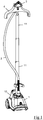
- the figure 1 show a steam ironing appliance comprising a base 1 for the generation of steam connected by a flexible duct 2 to a smoothing brush 3 comprising holes for the emission of steam, the base 1 comprising, in a manner known per se, a water tank 10 connected to a boiling chamber, not shown in the figures, allowing continuous production a flow of steam saturated with water, the boiling chamber being connected directly to the flexible duct 2 so that the steam produced by the boiling chamber can escape freely towards the anti-crease brush 3.
- Such a base 1 for the generation of steam is well known to those skilled in the art and is for example technically similar to the base for the generation of steam described in detail in the patent application. WO 2004/023957 .
- the base 1 comprises a mast 11 comprising three telescopic sections extending substantially vertically when the base 1 rests flat on the ground, the mast 11 comprising an upper end supporting a hanger 4 on which the laundry to be smoothed can be willing.
- the hanger 4 is advantageously made of plastic material and has a notch 40 at its top, better visible on the figure 2 , which forms a receiving housing for the anti-crease brush 3.
- the hanger 4 is mounted to pivot on the mast 11 about an axis coaxial with the longitudinal axis of the mast 11, the rotation of the hanger 4 being obtained by means of a pivot connection comprising a shaft 5, integral with the hanger 4, which rotates in a bearing 6 carried by a sleeve 60 arranged at the upper end of the mast 11.
- the apparatus comprises a locking device which makes it possible to immobilize the hanger 4 in position, the locking device comprising a control lever 7 which can occupy an unlocked position in which the hanger 4 can rotate freely. on the mast 11 and a locked position in which the hanger 4 is immobilized in position.
- the locking device comprises an elastically deformable braking element 8 disposed at a lower end of the shaft 5, inside the bearing 6, the braking element 8 being sandwiched between the lower end of the shaft 5 and a disc 80 fixed to a lower end of a rod 81 slidably mounted in the shaft 5 and the upper end of which is connected to the control lever 7.
- the braking element is advantageously constituted by an elastic spacer 8, made of elastomeric material, with a thickness of the order of 1 cm which is crossed by the rod 81, the elastic spacer 8 having an annular shape which, when it is not compressed, has an external diameter of the order of 2 cm, corresponding to the diameter of the shaft 5.
- the rod 81 has a cross-section in the form of a cross which slides in an opening 50 of complementary shape made in the center of the shaft 5 in order to prevent the rotation of the rod 81 on itself.
- the rod 81 has an upper end which opens, outside the hanger 4, into a cavity 41 formed at the base of the notch 40 intended to receive the anti-crease head 3, the upper end of the rod 81 being connected to the control lever 7 by a pivot connection of axis 82 perpendicular to the longitudinal axis of the rod 81.
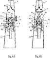
- the control lever 7 comprises an upper part 70 forming a gripping zone and a lower part forming a cam 71 which comes into contact with a wall 42 formed in the bottom of the cavity 41, the cam 71 having a shape adapted to cause the translational movement of the rod 81 in the direction of the approach of the disc 80 towards the lower end of the shaft 5 when the control lever 7 switches from the unlocked position, illustrated in the figure figure 4A , in the locked position, shown on the figure 4B .
- the part of the wall 42 on which the cam 71 comes to bear comprises a metal washer 43 which locally reinforces the bearing zone to prevent too rapid wear of the wall 42 in contact with the cam 71 during manipulation of the control lever 7.
- Such a locking device therefore has the advantage of being simple and economical to produce and allows the hanger to be immobilized in any angular position.
- such a locking device has the advantage of not breaking when the user forces the hanger to rotate it without having first positioned the control lever in the unlocked position. In fact, when such a case occurs, the elastic spacer begins to slide inside the bearing when the torque exerted becomes greater than the frictional forces, preventing any breakage of the locking device.
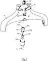
- the figures 5 , 6A and 6B illustrate a second embodiment of the device for locking the hanger 4 in rotation which can be fitted to the device of the figure 1 , the hanger 4 being mounted to pivot on the mast 11 by means of a pivot connection comprising a shaft 106, hollow, arranged at the upper end of the mast 11, the rotating shaft 106 in a bearing 105 formed in a sleeve 151 integral with the hanger 4 and being coaxial with the longitudinal axis of the mast 11.
- the locking device comprises a braking element constituted by a flange 108 made of a rigid plastic material of the polycarbonate type and has a generally frustoconical shape.
- the flange 108 is placed in a sleeve 160 attached to the inside of the shaft 106 and made integral in rotation with the latter by the insertion of fingers 161 carried by the internal surface of the shaft 106 in slots 162 formed on the latter. shirt 160.
- the sleeve 160 is inserted into the hollow shaft 106 through the top of the latter and has an upper end closed by a frustoconical wall 163 comprising a lower surface having a shape complementary to the frustoconical flange 108.
- the flange 108 is fixed to the lower end of a rod 181 passing through an opening 163A formed at the top of the frustoconical wall 163 and is mounted to slide in translation in an opening 152 formed at the upper end of the sleeve 151, the rod 181 having a non-circular cross section cooperating with the shape of the opening 152 to prevent the rotation of the rod 181 in the opening 152 so that the hanger 4 is integral in rotation with the rod 181.
- the rod 181 and the opening 152 have a rectangular cross section.
- the rod 181 has an upper end which opens into the cavity 41 formed at the base of the notch 40 of the hanger, the upper end of the rod 181 being connected to a control lever 107 by a pivot linkage 182 perpendicular to the longitudinal axis of the rod 181.
- the control lever 107 comprises an upper part forming a gripping zone and a lower part forming a cam 171 which comes into contact with a wall 142 formed in the bottom of the cavity 41, the cam 171 having a shape adapted to cause the translational displacement of the rod 181 in the direction of the pressurization of the flange 108 against the frustoconical wall 163 of the sleeve 160 when the control lever 107 rocks from the unlocked position illustrated, on the figure 6A , in the locked position shown on the figure 6B .
- the sleeve 151 can rotate freely on the shaft 106 and the hanger 4 can be manually oriented by the user in the position he wishes.
- the liner 160 being made integral by rotation of the shaft 106 by the insertion of the fingers 161 in the slots 162, the locking in rotation of the rod 181 relative to the shaft 106 prevents the rotation of the hanger 4 on the mast 11 which is then immobilized in position . The user can then perform ironing operations without risk of the hanger 4 rotating.
- the locking device according to this second embodiment has the advantage of being simple and economical to produce and of ensuring a more powerful rotation locking than that described in the first embodiment thanks to the friction of the flange made of rigid material. against the tapered wall of the liner.
- the apparatus may include, in addition to the hanger, an upper bar provided with clips, extending between the two longitudinal ends of the hanger, making it possible to hold the garment to be ironed.
- the hanger may also include an ironing surface, such as a curtain, which can be stretched vertically between the hanger and a lower bar attached to the mast.
- an ironing surface such as a curtain
- control member of the locking device may be constituted by a lever mounted to rotate about the longitudinal axis of the rod, the lever coming to rest on a wall provided with reliefs forming cams so that the rotation of the lever around the longitudinal axis of the rod causes the lever to move in translation along this longitudinal axis.
Landscapes
- Engineering & Computer Science (AREA)
- Textile Engineering (AREA)
- Holders For Apparel And Elements Relating To Apparel (AREA)
- Irons (AREA)
Claims (10)
- Dampfbügeleinrichtung, umfassend eine Basis (1), die eine Vorrichtung zur Erzeugung eines Dampfstroms umschließt, die durch eine Leitung (2) mit einem Glättungszubehör (3) verbunden ist, das mindestens ein Loch zum Ausgeben von Dampf umfasst, wobei die Basis (1) einen Bügel (4) umfasst, auf den das zu glättende Kleidungsstück während der Verwendung des Glättungszubehörs (3) angeordnet werden kann, wobei der Bügel (4) auf der Basis um eine Achse mittels eines Schwenkgelenks schwenkbar montiert ist und mittels einer Verriegelungsvorrichtung drehfest fixiert werden kann, wobei die Verriegelungsvorrichtung ein Steuerelement (7; 107) umfasst, das manuell durch einen Benutzer von einer entriegelten Position, die eine freie Drehung des Bügels (4) ermöglicht, zu einer verriegelten Position bewegt werden kann, in der der Bügel (4) drehfest fixiert ist, dadurch gekennzeichnet, dass die Bewegung des Steuerelements (7; 107) von der entriegelten Position in die verriegelte Position die Verschiebung und/oder die Verformung eines Bremselements (8; 108) von einer Ausgangsposition, die die freie Drehung des Schwenkgelenks ermöglicht, zu einer gebremsten Position verursacht, in der das Bremselement (8; 108) gegen ein Element (6, 163) unter Druck gehalten wird, um die Drehung des Bügels (4) zu verhindern, und die Verriegelung des Bügels um die Achse in irgendeiner Winkelposition ermöglicht.
- Bügeleinrichtung nach Anspruch 1, dadurch gekennzeichnet, dass das Bremselement (8; 108) an einer Stange (81; 181) translationsfest verbunden ist, und dass das Steuerelement aus einem Steuerhebel (7; 107) besteht, der schwenkbar an einem Ende der Stange (81; 181) angebracht ist, wobei der Steuerhebel (7; 107) einen Abschnitt umfasst, der einen Nocken (71; 171) bildet, der die Translationsverschiebung der Stange (81; 181) während des Schwenkens des Steuerhebels (7; 107) verursacht.
- Bügeleinrichtung nach Anspruch 2, dadurch gekennzeichnet, dass der Steuerhebel (7; 107) um einen Winkel zwischen 45° und 90° schwenkt, um von der entriegelten Position in die verriegelte Position zu gelangen, und dass der Steuerhebel (7; 107) vorteilhafterweise im Wesentlichen senkrecht zu der Stange (81; 181) angeordnet ist, wenn er eine der verriegelten oder entriegelten Position einnimmt, und in Ausrichtung zu der Stange (81; 181) angeordnet ist, wenn er die andere Position einnimmt.
- Bügeleinrichtung nach einem der Ansprüche 2 bis 3, dadurch gekennzeichnet, dass das Bremselement (8) ein elastisch verformbares Element ist, das von einer Ausgangsform zu einer modifizierten Form unter der Kraft, die von einem Teil (80), das an der Stange (81) befestigt ist, ausgeübt wird, übergeht, wenn der Steuerhebel (7) von der entriegelten Position in die verriegelte Position übergeht.
- Bügeleinrichtung nach Anspruch 4, dadurch gekennzeichnet, dass das Schwenkgelenk, das die Drehung des Bügels (4) an der Basis (1) ermöglicht, eine Welle (5) umfasst, die drehbar in einem Lager (6) montiert ist, und dass das Bremselement (8) zwischen einer Scheibe (80) und einem Ende der Welle (5) zusammengedrückt ist, wenn der Steuerhebel (7) die verriegelte Position einnimmt.
- Bügeleinrichtung nach einem der Ansprüche 1 bis 3, dadurch gekennzeichnet, dass das Bremselement (108) aus einem starren Flansch mit vorteilhafterweise kegelstumpfförmiger Form besteht.
- Einrichtung nach Anspruch 6, dadurch gekennzeichnet, dass die Schwenkverbindung, die die Drehung des Bügels (4) an der Basis (1) ermöglicht, eine hohle Welle (106) umfasst, die drehbar in einem Lager (105) montiert ist, und dass der Flansch (108) in einem Mantel (160) angeordnet ist, der an einem Ende der Welle (106) befestigt ist.
- Einrichtung nach einem der Ansprüche 1 bis 7, dadurch gekennzeichnet, dass das Steuerelement (7; 107) in einem Hohlraum (41) des Bügels angeordnet ist, wobei der Hohlraum (41) vorteilhafterweise auf zwei gegenüberliegenden Seiten des Bügels (4) mündet.
- Einrichtung nach einem der Ansprüche 1 bis 8, dadurch gekennzeichnet, dass die Basis (1) einen vertikalen Mast (11) umfasst, der vorteilhafterweise teleskopisch ist, und der den Bügel (4) trägt.
- Einrichtung nach einem der Ansprüche 1 bis 9, dadurch gekennzeichnet, dass das Zubehör (3) eine Glättungsbürste (3) oder ein Bügeleisen ist.
Applications Claiming Priority (3)
| Application Number | Priority Date | Filing Date | Title |
|---|---|---|---|
| FR1561028A FR3043701B1 (fr) | 2015-11-17 | 2015-11-17 | Appareil de repassage a la vapeur comportant un cintre pour disposer le vetement a defroisser |
| CN201510790212.9A CN106702704B (zh) | 2015-11-17 | 2015-11-17 | 包括用于放置待熨烫衣服的衣架的蒸汽式熨烫设备 |
| PCT/FR2016/052947 WO2017085388A1 (fr) | 2015-11-17 | 2016-11-14 | Appareil de repassage à la vapeur comportant un cintre pour disposer le vêtement a défroisser |
Publications (2)
| Publication Number | Publication Date |
|---|---|
| EP3377689A1 EP3377689A1 (de) | 2018-09-26 |
| EP3377689B1 true EP3377689B1 (de) | 2020-09-23 |
Family
ID=57543067
Family Applications (1)
| Application Number | Title | Priority Date | Filing Date |
|---|---|---|---|
| EP16809989.3A Active EP3377689B1 (de) | 2015-11-17 | 2016-11-14 | Gerät zum dampfbügeln mit aufhänger zum glätten von kleidungsstücken |
Country Status (3)
| Country | Link |
|---|---|
| US (1) | US10648126B2 (de) |
| EP (1) | EP3377689B1 (de) |
| WO (1) | WO2017085388A1 (de) |
Citations (1)
| Publication number | Priority date | Publication date | Assignee | Title |
|---|---|---|---|---|
| US4497092A (en) * | 1982-07-12 | 1985-02-05 | Hoshino Gakki Company, Ltd. | Device for fixing rods in selected relative position |
Family Cites Families (10)
| Publication number | Priority date | Publication date | Assignee | Title |
|---|---|---|---|---|
| US4892279A (en) * | 1987-05-04 | 1990-01-09 | Polymedical Technologies, Inc. | Fully portable medical I.V. equipment stand/pole |
| US5609047A (en) * | 1995-06-06 | 1997-03-11 | Nadia Wechsler | Garment steaming device with safety nozzle |
| US6886373B2 (en) * | 2002-09-13 | 2005-05-03 | Conair Corporation | Garment steamer |
| US8091747B2 (en) * | 2006-03-17 | 2012-01-10 | Gyung-Hee Haan | Hanger for garment steamer |
| WO2007108577A1 (en) * | 2006-03-17 | 2007-09-27 | Gyung-Hee Hahn | Garment steamer |
| WO2008021273A2 (en) * | 2006-08-15 | 2008-02-21 | Conair Corporation | Steamer and hot iron appliance |
| US20080217364A1 (en) | 2007-03-09 | 2008-09-11 | Pou Veng Fong | Extending pole and rotatable hanger for clothing appliance |
| US9091016B2 (en) * | 2010-10-20 | 2015-07-28 | Euro-Pro Operating Llc | Garment steamer |
| CN203360893U (zh) | 2013-07-01 | 2013-12-25 | 宁波哲恺电器有限公司 | 挂烫机用旋转衣架 |
| FR3012475B1 (fr) * | 2013-10-31 | 2015-10-23 | Seb Sa | Appareil electromenager comportant une base generatrice de vapeur reliee par un conduit de vapeur a un outil pour le defroissage vertical du linge |
-
2016
- 2016-11-14 WO PCT/FR2016/052947 patent/WO2017085388A1/fr not_active Ceased
- 2016-11-14 EP EP16809989.3A patent/EP3377689B1/de active Active
- 2016-11-14 US US15/776,664 patent/US10648126B2/en active Active
Patent Citations (1)
| Publication number | Priority date | Publication date | Assignee | Title |
|---|---|---|---|---|
| US4497092A (en) * | 1982-07-12 | 1985-02-05 | Hoshino Gakki Company, Ltd. | Device for fixing rods in selected relative position |
Also Published As
| Publication number | Publication date |
|---|---|
| EP3377689A1 (de) | 2018-09-26 |
| WO2017085388A1 (fr) | 2017-05-26 |
| US20180327961A1 (en) | 2018-11-15 |
| US10648126B2 (en) | 2020-05-12 |
Similar Documents
| Publication | Publication Date | Title |
|---|---|---|
| EP3421658B1 (de) | Dampfbügel- und/oder entknitterungsgerät, das ein bügelbrett umfasst, das in verschiedenen neigungswinkeln festgestellt werden kann | |
| EP2687132B1 (de) | Druckkochgerät mit verbesserter Bedienungsvorrichtung | |
| FR2929354A1 (fr) | Dispositif de verrouillage pour canne telescopique et appareil muni d'un tel dispositif de verrouillage | |
| EP3233617B1 (de) | Zusammenklappbarer tretroller | |
| FR2997141A3 (fr) | Mousqueton de securite a double blocage | |
| EP2659149B1 (de) | Vorrichtung zum gegenseitigen verriegeln zweier gleitbare montierbarer rohre | |
| FR2998152A1 (fr) | Appareil de cuisson d'aliments sous pression comportant un organe de commande ameliore | |
| EP2335533B1 (de) | Haushaltsgerät zur Essenszubereitung, das zum Halten in der Hand konzipiert und mit einer speziellen Steuervorrichtung ausgestattet ist | |
| EP2933372A1 (de) | Elektrohaushaltsgerät, das ein bügeleisen und eine tragbare basis umfasst, die einen abstellort für das bügeleisen beinhaltet | |
| WO2013150236A1 (fr) | Poignee amovible cooperant avec une anse | |
| EP2933371B1 (de) | Elektrisches haushaltsgerät für den handbetrieb, das eine vorrichtung zum bügeln und/oder entknittern enthält, und tragbare basis | |
| EP3377689B1 (de) | Gerät zum dampfbügeln mit aufhänger zum glätten von kleidungsstücken | |
| FR3043701A1 (fr) | Appareil de repassage a la vapeur comportant un cintre pour disposer le vetement a defroisser | |
| EP3613894B1 (de) | Bügelgerät, das ein bügeleisen und eine tragbare station mit einem schwenkbaren griff umfasst | |
| FR2467612A1 (fr) | Frein de ski | |
| BE1021722B1 (fr) | Dispositif pour goupilles | |
| EP2312974B1 (de) | Klemmenartiger kleiderbügel | |
| EP3754097B1 (de) | Bügelvorrichtung mit einem bügelbrett | |
| FR2816276A1 (fr) | Poignees laterales orientables pour guidon de cycle | |
| EP3152011A1 (de) | Schlüssel zur betätigung mehrerer humanoider robotermechanismen | |
| BE565491A (de) | ||
| FR2912337A1 (fr) | Dispositif d'ouverture semi-automatique d'un couteau. | |
| CA2480207A1 (fr) | Dispositif de verrouillage/deverrouillage d'un manchon d'application de peinture sur une monture | |
| FR2785776A1 (fr) | Brosse a dents a boitier de protection mobile le long de son manche | |
| FR2573691A1 (fr) | Pince pneumatique pour le serrage de colliers |
Legal Events
| Date | Code | Title | Description |
|---|---|---|---|
| STAA | Information on the status of an ep patent application or granted ep patent |
Free format text: STATUS: UNKNOWN |
|
| STAA | Information on the status of an ep patent application or granted ep patent |
Free format text: STATUS: THE INTERNATIONAL PUBLICATION HAS BEEN MADE |
|
| PUAI | Public reference made under article 153(3) epc to a published international application that has entered the european phase |
Free format text: ORIGINAL CODE: 0009012 |
|
| STAA | Information on the status of an ep patent application or granted ep patent |
Free format text: STATUS: REQUEST FOR EXAMINATION WAS MADE |
|
| 17P | Request for examination filed |
Effective date: 20180504 |
|
| AK | Designated contracting states |
Kind code of ref document: A1 Designated state(s): AL AT BE BG CH CY CZ DE DK EE ES FI FR GB GR HR HU IE IS IT LI LT LU LV MC MK MT NL NO PL PT RO RS SE SI SK SM TR |
|
| AX | Request for extension of the european patent |
Extension state: BA ME |
|
| DAV | Request for validation of the european patent (deleted) | ||
| DAX | Request for extension of the european patent (deleted) | ||
| STAA | Information on the status of an ep patent application or granted ep patent |
Free format text: STATUS: EXAMINATION IS IN PROGRESS |
|
| 17Q | First examination report despatched |
Effective date: 20190516 |
|
| REG | Reference to a national code |
Ref country code: DE Ref legal event code: R079 Ref document number: 602016044636 Country of ref document: DE Free format text: PREVIOUS MAIN CLASS: D06F0073000000 Ipc: D06F0058100000 |
|
| GRAP | Despatch of communication of intention to grant a patent |
Free format text: ORIGINAL CODE: EPIDOSNIGR1 |
|
| STAA | Information on the status of an ep patent application or granted ep patent |
Free format text: STATUS: GRANT OF PATENT IS INTENDED |
|
| RIC1 | Information provided on ipc code assigned before grant |
Ipc: D06F 58/10 20060101AFI20200515BHEP Ipc: D06F 73/02 20060101ALI20200515BHEP |
|
| INTG | Intention to grant announced |
Effective date: 20200624 |
|
| GRAS | Grant fee paid |
Free format text: ORIGINAL CODE: EPIDOSNIGR3 |
|
| GRAA | (expected) grant |
Free format text: ORIGINAL CODE: 0009210 |
|
| STAA | Information on the status of an ep patent application or granted ep patent |
Free format text: STATUS: THE PATENT HAS BEEN GRANTED |
|
| AK | Designated contracting states |
Kind code of ref document: B1 Designated state(s): AL AT BE BG CH CY CZ DE DK EE ES FI FR GB GR HR HU IE IS IT LI LT LU LV MC MK MT NL NO PL PT RO RS SE SI SK SM TR |
|
| REG | Reference to a national code |
Ref country code: GB Ref legal event code: FG4D Free format text: NOT ENGLISH |
|
| REG | Reference to a national code |
Ref country code: CH Ref legal event code: EP |
|
| REG | Reference to a national code |
Ref country code: IE Ref legal event code: FG4D Free format text: LANGUAGE OF EP DOCUMENT: FRENCH |
|
| REG | Reference to a national code |
Ref country code: DE Ref legal event code: R096 Ref document number: 602016044636 Country of ref document: DE Ref country code: AT Ref legal event code: REF Ref document number: 1316476 Country of ref document: AT Kind code of ref document: T Effective date: 20201015 |
|
| PG25 | Lapsed in a contracting state [announced via postgrant information from national office to epo] |
Ref country code: FI Free format text: LAPSE BECAUSE OF FAILURE TO SUBMIT A TRANSLATION OF THE DESCRIPTION OR TO PAY THE FEE WITHIN THE PRESCRIBED TIME-LIMIT Effective date: 20200923 Ref country code: GR Free format text: LAPSE BECAUSE OF FAILURE TO SUBMIT A TRANSLATION OF THE DESCRIPTION OR TO PAY THE FEE WITHIN THE PRESCRIBED TIME-LIMIT Effective date: 20201224 Ref country code: NO Free format text: LAPSE BECAUSE OF FAILURE TO SUBMIT A TRANSLATION OF THE DESCRIPTION OR TO PAY THE FEE WITHIN THE PRESCRIBED TIME-LIMIT Effective date: 20201223 Ref country code: BG Free format text: LAPSE BECAUSE OF FAILURE TO SUBMIT A TRANSLATION OF THE DESCRIPTION OR TO PAY THE FEE WITHIN THE PRESCRIBED TIME-LIMIT Effective date: 20201223 Ref country code: HR Free format text: LAPSE BECAUSE OF FAILURE TO SUBMIT A TRANSLATION OF THE DESCRIPTION OR TO PAY THE FEE WITHIN THE PRESCRIBED TIME-LIMIT Effective date: 20200923 Ref country code: SE Free format text: LAPSE BECAUSE OF FAILURE TO SUBMIT A TRANSLATION OF THE DESCRIPTION OR TO PAY THE FEE WITHIN THE PRESCRIBED TIME-LIMIT Effective date: 20200923 |
|
| REG | Reference to a national code |
Ref country code: AT Ref legal event code: MK05 Ref document number: 1316476 Country of ref document: AT Kind code of ref document: T Effective date: 20200923 |
|
| PG25 | Lapsed in a contracting state [announced via postgrant information from national office to epo] |
Ref country code: RS Free format text: LAPSE BECAUSE OF FAILURE TO SUBMIT A TRANSLATION OF THE DESCRIPTION OR TO PAY THE FEE WITHIN THE PRESCRIBED TIME-LIMIT Effective date: 20200923 Ref country code: LV Free format text: LAPSE BECAUSE OF FAILURE TO SUBMIT A TRANSLATION OF THE DESCRIPTION OR TO PAY THE FEE WITHIN THE PRESCRIBED TIME-LIMIT Effective date: 20200923 |
|
| REG | Reference to a national code |
Ref country code: NL Ref legal event code: MP Effective date: 20200923 |
|
| REG | Reference to a national code |
Ref country code: LT Ref legal event code: MG4D |
|
| PG25 | Lapsed in a contracting state [announced via postgrant information from national office to epo] |
Ref country code: SM Free format text: LAPSE BECAUSE OF FAILURE TO SUBMIT A TRANSLATION OF THE DESCRIPTION OR TO PAY THE FEE WITHIN THE PRESCRIBED TIME-LIMIT Effective date: 20200923 Ref country code: EE Free format text: LAPSE BECAUSE OF FAILURE TO SUBMIT A TRANSLATION OF THE DESCRIPTION OR TO PAY THE FEE WITHIN THE PRESCRIBED TIME-LIMIT Effective date: 20200923 Ref country code: CZ Free format text: LAPSE BECAUSE OF FAILURE TO SUBMIT A TRANSLATION OF THE DESCRIPTION OR TO PAY THE FEE WITHIN THE PRESCRIBED TIME-LIMIT Effective date: 20200923 Ref country code: RO Free format text: LAPSE BECAUSE OF FAILURE TO SUBMIT A TRANSLATION OF THE DESCRIPTION OR TO PAY THE FEE WITHIN THE PRESCRIBED TIME-LIMIT Effective date: 20200923 Ref country code: PT Free format text: LAPSE BECAUSE OF FAILURE TO SUBMIT A TRANSLATION OF THE DESCRIPTION OR TO PAY THE FEE WITHIN THE PRESCRIBED TIME-LIMIT Effective date: 20210125 Ref country code: LT Free format text: LAPSE BECAUSE OF FAILURE TO SUBMIT A TRANSLATION OF THE DESCRIPTION OR TO PAY THE FEE WITHIN THE PRESCRIBED TIME-LIMIT Effective date: 20200923 |
|
| PG25 | Lapsed in a contracting state [announced via postgrant information from national office to epo] |
Ref country code: AT Free format text: LAPSE BECAUSE OF FAILURE TO SUBMIT A TRANSLATION OF THE DESCRIPTION OR TO PAY THE FEE WITHIN THE PRESCRIBED TIME-LIMIT Effective date: 20200923 Ref country code: AL Free format text: LAPSE BECAUSE OF FAILURE TO SUBMIT A TRANSLATION OF THE DESCRIPTION OR TO PAY THE FEE WITHIN THE PRESCRIBED TIME-LIMIT Effective date: 20200923 Ref country code: ES Free format text: LAPSE BECAUSE OF FAILURE TO SUBMIT A TRANSLATION OF THE DESCRIPTION OR TO PAY THE FEE WITHIN THE PRESCRIBED TIME-LIMIT Effective date: 20200923 Ref country code: IS Free format text: LAPSE BECAUSE OF FAILURE TO SUBMIT A TRANSLATION OF THE DESCRIPTION OR TO PAY THE FEE WITHIN THE PRESCRIBED TIME-LIMIT Effective date: 20210123 Ref country code: PL Free format text: LAPSE BECAUSE OF FAILURE TO SUBMIT A TRANSLATION OF THE DESCRIPTION OR TO PAY THE FEE WITHIN THE PRESCRIBED TIME-LIMIT Effective date: 20200923 |
|
| REG | Reference to a national code |
Ref country code: DE Ref legal event code: R097 Ref document number: 602016044636 Country of ref document: DE |
|
| PG25 | Lapsed in a contracting state [announced via postgrant information from national office to epo] |
Ref country code: SK Free format text: LAPSE BECAUSE OF FAILURE TO SUBMIT A TRANSLATION OF THE DESCRIPTION OR TO PAY THE FEE WITHIN THE PRESCRIBED TIME-LIMIT Effective date: 20200923 Ref country code: MC Free format text: LAPSE BECAUSE OF FAILURE TO SUBMIT A TRANSLATION OF THE DESCRIPTION OR TO PAY THE FEE WITHIN THE PRESCRIBED TIME-LIMIT Effective date: 20200923 |
|
| REG | Reference to a national code |
Ref country code: CH Ref legal event code: PL |
|
| PG25 | Lapsed in a contracting state [announced via postgrant information from national office to epo] |
Ref country code: LU Free format text: LAPSE BECAUSE OF NON-PAYMENT OF DUE FEES Effective date: 20201114 |
|
| PLBE | No opposition filed within time limit |
Free format text: ORIGINAL CODE: 0009261 |
|
| STAA | Information on the status of an ep patent application or granted ep patent |
Free format text: STATUS: NO OPPOSITION FILED WITHIN TIME LIMIT |
|
| REG | Reference to a national code |
Ref country code: BE Ref legal event code: MM Effective date: 20201130 |
|
| GBPC | Gb: european patent ceased through non-payment of renewal fee |
Effective date: 20201223 |
|
| PG25 | Lapsed in a contracting state [announced via postgrant information from national office to epo] |
Ref country code: DK Free format text: LAPSE BECAUSE OF FAILURE TO SUBMIT A TRANSLATION OF THE DESCRIPTION OR TO PAY THE FEE WITHIN THE PRESCRIBED TIME-LIMIT Effective date: 20200923 Ref country code: CH Free format text: LAPSE BECAUSE OF NON-PAYMENT OF DUE FEES Effective date: 20201130 Ref country code: LI Free format text: LAPSE BECAUSE OF NON-PAYMENT OF DUE FEES Effective date: 20201130 Ref country code: SI Free format text: LAPSE BECAUSE OF FAILURE TO SUBMIT A TRANSLATION OF THE DESCRIPTION OR TO PAY THE FEE WITHIN THE PRESCRIBED TIME-LIMIT Effective date: 20200923 |
|
| 26N | No opposition filed |
Effective date: 20210624 |
|
| PG25 | Lapsed in a contracting state [announced via postgrant information from national office to epo] |
Ref country code: IE Free format text: LAPSE BECAUSE OF NON-PAYMENT OF DUE FEES Effective date: 20201114 |
|
| PG25 | Lapsed in a contracting state [announced via postgrant information from national office to epo] |
Ref country code: GB Free format text: LAPSE BECAUSE OF NON-PAYMENT OF DUE FEES Effective date: 20201223 |
|
| PG25 | Lapsed in a contracting state [announced via postgrant information from national office to epo] |
Ref country code: IS Free format text: LAPSE BECAUSE OF FAILURE TO SUBMIT A TRANSLATION OF THE DESCRIPTION OR TO PAY THE FEE WITHIN THE PRESCRIBED TIME-LIMIT Effective date: 20210123 Ref country code: TR Free format text: LAPSE BECAUSE OF FAILURE TO SUBMIT A TRANSLATION OF THE DESCRIPTION OR TO PAY THE FEE WITHIN THE PRESCRIBED TIME-LIMIT Effective date: 20200923 Ref country code: MT Free format text: LAPSE BECAUSE OF FAILURE TO SUBMIT A TRANSLATION OF THE DESCRIPTION OR TO PAY THE FEE WITHIN THE PRESCRIBED TIME-LIMIT Effective date: 20200923 Ref country code: CY Free format text: LAPSE BECAUSE OF FAILURE TO SUBMIT A TRANSLATION OF THE DESCRIPTION OR TO PAY THE FEE WITHIN THE PRESCRIBED TIME-LIMIT Effective date: 20200923 |
|
| PG25 | Lapsed in a contracting state [announced via postgrant information from national office to epo] |
Ref country code: MK Free format text: LAPSE BECAUSE OF FAILURE TO SUBMIT A TRANSLATION OF THE DESCRIPTION OR TO PAY THE FEE WITHIN THE PRESCRIBED TIME-LIMIT Effective date: 20200923 |
|
| PG25 | Lapsed in a contracting state [announced via postgrant information from national office to epo] |
Ref country code: BE Free format text: LAPSE BECAUSE OF NON-PAYMENT OF DUE FEES Effective date: 20201130 |
|
| PG25 | Lapsed in a contracting state [announced via postgrant information from national office to epo] |
Ref country code: NL Free format text: LAPSE BECAUSE OF NON-PAYMENT OF DUE FEES Effective date: 20200923 |
|
| PGFP | Annual fee paid to national office [announced via postgrant information from national office to epo] |
Ref country code: DE Payment date: 20241108 Year of fee payment: 9 |
|
| PGFP | Annual fee paid to national office [announced via postgrant information from national office to epo] |
Ref country code: IT Payment date: 20241108 Year of fee payment: 9 |
|
| PGFP | Annual fee paid to national office [announced via postgrant information from national office to epo] |
Ref country code: FR Payment date: 20251127 Year of fee payment: 10 |