EP3378582B1 - Équipement de coulée et procédé de coulée - Google Patents
Équipement de coulée et procédé de coulée Download PDFInfo
- Publication number
- EP3378582B1 EP3378582B1 EP16866589.1A EP16866589A EP3378582B1 EP 3378582 B1 EP3378582 B1 EP 3378582B1 EP 16866589 A EP16866589 A EP 16866589A EP 3378582 B1 EP3378582 B1 EP 3378582B1
- Authority
- EP
- European Patent Office
- Prior art keywords
- nozzle
- ladle
- hanger
- mold
- mounting
- Prior art date
- Legal status (The legal status is an assumption and is not a legal conclusion. Google has not performed a legal analysis and makes no representation as to the accuracy of the status listed.)
- Active
Links
Images



Classifications
-
- B—PERFORMING OPERATIONS; TRANSPORTING
- B22—CASTING; POWDER METALLURGY
- B22D—CASTING OF METALS; CASTING OF OTHER SUBSTANCES BY THE SAME PROCESSES OR DEVICES
- B22D41/00—Casting melt-holding vessels, e.g. ladles, tundishes, cups or the like
- B22D41/50—Pouring-nozzles
- B22D41/56—Means for supporting, manipulating or changing a pouring-nozzle
-
- B—PERFORMING OPERATIONS; TRANSPORTING
- B22—CASTING; POWDER METALLURGY
- B22D—CASTING OF METALS; CASTING OF OTHER SUBSTANCES BY THE SAME PROCESSES OR DEVICES
- B22D41/00—Casting melt-holding vessels, e.g. ladles, tundishes, cups or the like
- B22D41/12—Travelling ladles or similar containers; Cars for ladles
-
- B—PERFORMING OPERATIONS; TRANSPORTING
- B22—CASTING; POWDER METALLURGY
- B22D—CASTING OF METALS; CASTING OF OTHER SUBSTANCES BY THE SAME PROCESSES OR DEVICES
- B22D41/00—Casting melt-holding vessels, e.g. ladles, tundishes, cups or the like
- B22D41/14—Closures
- B22D41/22—Closures sliding-gate type, i.e. having a fixed plate and a movable plate in sliding contact with each other for selective registry of their openings
- B22D41/24—Closures sliding-gate type, i.e. having a fixed plate and a movable plate in sliding contact with each other for selective registry of their openings characterised by a rectilinearly movable plate
-
- B—PERFORMING OPERATIONS; TRANSPORTING
- B22—CASTING; POWDER METALLURGY
- B22D—CASTING OF METALS; CASTING OF OTHER SUBSTANCES BY THE SAME PROCESSES OR DEVICES
- B22D41/00—Casting melt-holding vessels, e.g. ladles, tundishes, cups or the like
- B22D41/50—Pouring-nozzles
- B22D41/505—Rings, inserts or other means preventing external nozzle erosion by the slag
Definitions
- the present invention relates to a casting facility and a casting method, and more particularly, to a casting facility capable of adjusting balance between a ladle and a nozzle such that the ladle may always be positioned in the same position in positioning the ladle in the casting position, and a casting method.
- JP S 56 80960 U discloses a ladle for receiving steel.
- KR 2013 0088310 A describes a ladle for receiving steel.
- it is furthermore referred to KR 2013 0075570 A and KR 2010 0128988 A .
- a continuous casting process includes a ladle for receiving the refined molten steel in a steelmaking process, a tundish for temporarily receiving the molten steel provided from the ladle, a shroud nozzle for supplying the molten steel of the ladle to the tundish, a mold for solidifying the melting steel supplied from the tundish into a predetermined shape to be casted into a cast slab, and a plurality of segments aligned and installed in one direction in the lower portion of the mold, and cooling the cast slab drawn from the mold.
- a ladle turret as illustrated in Korean Patent Laid-Open Publication No. 2013-0120149 is used.
- the ladle turret includes a swing tower which is rotationally driven, and ladle cradles installed so as to connected to both sides of the swing tower, and mounting ladles each thereon.
- ladles are alternately positioned at the upper portion of the tundish by the rotation of the swing tower and the molten steel of the ladle is discharged into the tundish, so that the casting is continuously performed.
- Such a ladle turret has an advantage in that the ladle may always be stably positioned at the same position at the upper portion of the tundish.
- the ladle turret is expensive and has a disadvantage in that the ladle receiving several hundreds of tons of molten steel is rotated, raised or lowered in order to be positioned at the casting position, so that a power consumption is large in the continuous casting process.
- the operation of the ladle turret as described above becomes a more inefficient factor in aspect of a power consumption.
- the verticality of shroud nozzle is an important factor in order to prevent molten steel from being re-oxidized by the mixing of the external air when the molten steel of the ladle is supplied to the tundish.
- the shroud nozzle includes a ladle nozzle connected to the lower portion of the ladle and, a long nozzle clamped to the lower portion of the ladle nozzle in order to supply the molten steel of the ladle into the tundish.
- such a shroud nozzle differs from a clamping position between the ladle nozzle and the long nozzle or a verticality formed by the ladle nozzle and the long nozzle. That is, when the shroud nozzle is clamped to the ladle nozzle, in the case that the shroud nozzle is shifted to any one side and the array is disturbed or the misalignment is occurred, the external air may be invaded between the ladle nozzle and the long nozzle to be mixed into the molten steel.
- 2013-0075570 includes a shroud arm composed so as to be movable forward and backward with respect to the long nozzle; a gripping part positioned in the lower side of the shroud arm, movable forward and backward with respect to the long nozzle, and capable of gripping the long nozzle; and a hydraulic moving means installed in the lower portion of the shroud arm and movable the gripping part forward and backward.
- the present invention provides a casting facility capable of always positioning a ladle in the same position and adjusting balance between the ladle and nozzles in positioning the ladle in the casting position, and a casting method.
- the present invention provides a casting facility disposed in the casting position by supporting the ladle with a simple structure and including a ladle support device capable of adjusting balance between the ladle and the nozzle, and a casting method.
- a casting facility in accordance with the present invention comprises a ladle for receiving molten steel; a mold for solidifying the molten steel provided from the ladle to be casted into a cast slab; a hanger extending in one direction, supporting the ladle, and being movable; a ladle gripping means extending in a vertical direction, and having one end connected to the hanger and the other end gripping the ladle; a hanger mounting part installed on an upper side of the mold, mounting the hanger for supporting the ladle thereon, and allowing the ladle supported by the hanger to be positioned corresponding to the upper side of the mold; and a nozzle connected to a lower portion of the ladle and discharging the molten steel of the ladle.
- the hanger mounting part may include a pair of first mounting stands extending in a direction crossing the extending direction of the hanger and installed apart from each other such that both edges of the hanger are installed on the upper portion; and a pair of second mounting stands installed so as to respectively extend upward from upper portions of the pair of first mounting stands and having two mounting members installed apart from each other by a distance lager than the width of the hanger.
- the casting facility may include a pair of stoppers installed at lower edges of the hanger, wherein the pair of stoppers are installed apart from each other by a distance shorter than a spaced distance between the pair of first mounting stands from lower portion of the hanger.
- the nozzle includes a first nozzle having the one end connected to the ladle, and a second nozzle capable of clamping to the first nozzle; a first balance adjustment part movable forward and backward, gripping the second nozzle to move in a direction in which the first nozzle is positioned, clamping the second nozzle to the first nozzle, and supporting the second nozzle; and a second balance adjustment part installed at a lower side of the hanger mounting part, movable forward and backward, and advancing to the ladle to which the nozzle clamped by the first and second nozzles is connected, thus supporting the ladle at a position opposite to the first balance adjustment part.
- the first balance adjustment part may be movable along the ladle, wherein the first balance adjustment part includes a nozzle gripping member capable of gripping the second nozzle; an arm connected to the nozzle gripping member and movable forward and backward; and a weight installable on the arm at a position opposite to the nozzle gripping member.
- the casting facility may include a support member installed at the lower portion of the ladle, and being able to support the arm.
- the second balance adjustment part may include a horizontal moving part movable forward and backward with respect to a side surface of the ladle at a position opposite to the first balance adjustment part, and supporting the ladle by being in contact with the side surface of the ladle during advancement.
- the casting facility may include a protrusion portion formed in any one of the first and second nozzles; and a clamping part provided on the other nozzle and having a clamping groove being able to receive the protrusion portion.
- the other end of the second nozzle is installed so as to be inserted into the mold, and the second balance adjustment part is fixed and installed on an upper portion of a mold cover for covering the upper portion of the mold.
- the casting facility may draw a cast slab in a direction perpendicular to the ground from the mold.
- the casting facility may include a tundish installed between the hanger mounting stand and the mold, and when the hanger is supported on the hanger mounting stand and the ladle is positioned on the upper side of the mold, the other end of the second nozzle is installed so as to be inserted into the tundish.
- the second balance adjustment part may be fixed and installed on an upper portion of a tundish cover for covering the upper portion of the tundish.
- a casting method includes: supporting a ladle receiving refined molten steel therein to a hanger; clamping a second nozzle to a first nozzle installed at a lower portion of the ladle; moving the hanger and mounting the hanger on a hanger mounting part positioned on an upper side of a mold, such that the ladle is positioned on the upper portion of the mold; moving the molten steel of the ladle through the nozzle to supply the molten steel to the mold; and solidifying the molten steel in the mold and drawing a cast slab form the mold, wherein the moving of the hanger and mounting of the hanger on a hanger mounting part positioned on an upper portion of a mold includes mounting each of one end and the other end of the hanger on upper portions of a pair of first mounting stands installed in a direction corresponding to the extending direction of the hanger.
- the moving of the hanger and mounting of the hanger on a hanger mounting part positioned on an upper portion of a mold may be performed such that one end and the other end of the hanger are positioned between two mounting members extending upward from upper portions of the pair of mounting stands and installed apart from in the width direction of the hanger.
- the clamping of the second nozzle to the first nozzle may include gripping the second nozzle to a nozzle gripping member being movable forward and backward; operating an arm connected to the nozzle gripping member and advancing the nozzle gripping member forward and backward, moving the nozzle gripping member to a lower side of the first nozzle, and clamping the second nozzle to the first nozzle; and installing an arm weight at a position opposite to the position of the nozzle gripping member.
- the method includes moving the hanger to the upper side of the mold, and then adjusting balance between the ladle and the first and second nozzles, wherein the adjusting of the balance includes operating a horizontal moving part installed in a lower side of the hanger mounting stand to advance a ladle support member connected to the horizontal moving part toward the ladle to allow the ladle support member to support a side surface of the ladle, whereby a force is applied in a direction where the nozzle gripping member is positioned such that the ladle, and the first and second nozzles are adjusted to be perpendicular to the ground.
- the operating of the horizontal moving part to allow the ladle support member to support the ladle may include advancing a first moving member connected to the ladle support member to contact the ladle support member with the outside surface of the ladle; and in a state in which a second moving member connected to the ladle support member and movable forward and backward finely relative to the first moving member is in contact with the ladle, advancing or retracting the second moving member, such that the ladle, and first and second nozzles are adjusted to be perpendicular to the ground without being tilted.
- the mounting of the hanger on the hanger mounting part positioned on the upper side of the mold to allow the ladle to be positioned on the upper side of the mold may include allowing the lower portion of the second nozzle to be inserted into the mold, wherein the supplying of the molten steel of the ladle to the mold includes supplying the molten steel of the ladle to the mold by the first nozzle and the second nozzle.
- the mounting of the hanger on the hanger mounting part positioned on the upper side of the mold to position the ladle on the upper side of the mold may include allowing the lower portion of the second nozzle to be inserted into the tundish positioned between the hanger mounting stand and the mold, wherein the supplying of the molten steel of the ladle to the mold includes supplying the molten steel of the ladle to the tundish by the first nozzle and the second nozzle.
- the cast slab may be drawn from the mold in a direction perpendicular to the ground to be vertical-casted, or the cast slab is curved-casted in a manner in which the cast slab is drawn from the mold in a vertical direction and then is casted in a horizontal direction.
- a ladle may always be stably fixed in the same position by hanger mounting stands. Further, the ladle and nozzles may be disposed so as to be perpendicular to the ground without being tilted to any one side, so that molten steel may be stably supplied to a mold or a tundish
- the hanger mounting stands in accordance with an embodiment has a simple structure compared to the conventional turret, and consumes less electric power for driving. Further, there is an advantage in that the first and second balance adjustment parts have simple structures compared to the conventional shroud manipulator, thus reducing the installation space and also having a low cost required for the manufacture and operation thereof.
- the present invention relates to a casting facility including a ladle support device for supporting a ladle in which molten steel is received in order to supply the molten steel received in the ladle to a mold or a tundish. More specifically, the present invention relates to a casting facility having an adjustable ladle support device such that the ladle in which the molten steel is received may always be stably positioned in the same position on the upper portion of the mold or the tundish, and a nozzle for discharging the molten steel is perpendicular to the ground without being tilted on the upper portion of the mold or the tundish.
- the ladle support device in accordance with an embodiment draws a cast slab from the mold in a direction perpendicular to the ground, and is applied to a semi-continuous vertical casting facility for casting a cast slab having an ultra-heavy gauge in thickness.
- the molten steel of the ladle is directly supplied to the mold, and the cast slab is casted in vertical.
- the molten steel of the ladle is supplied to the tundish, and the molten steel of the tundish is supplied to the mold to be casted.
- the molten steel of the ladle is directly supplied to the mold through the nozzle to be casted into a cast slab.
- the ladle support device in accordance with an embodiment is configured such that one ladle is supported.
- FIGS. 1 and 2 are views illustrating a casting facility in accordance with an embodiment of the present invention.
- FIG. 3A is a front view illustrating a first nozzle and a second nozzle in accordance with an embodiment of the present invention
- FIG. 3B is a top view
- FIG. 3C is an enlarged view for explaining a clamping part for clamping a first and second nozzles.
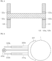
- FIG. 4 is a top view illustrating a hanger and a hanger mounting stand in which the hanger is mounted.
- FIG. 2 is a top view of a second balance adjustment part in accordance with an embodiment of the present invention as viewed from the upper side.
- FIG 6 is a view for explaining the operation of a ladle support device in accordance with an embodiment of the present invention.
- a casting facility in accordance with an embodiment of the present invention includes a ladle L for receiving refined molten steel; a mold M for solidifying the molten steel provided from the ladle L; a mold cover C for covering the upper side of the mold M; a nozzle 2000 for supplying the molten steel of the ladle L to the mold M; and a ladle support device 1000 supporting the ladle L in which molten steel is received to be positioned corresponding to the upper side of the mold M, and adjusting balance between the ladle L and the nozzle 2000.
- the casting facility includes a surface plate 10 for drawing a cast slab from the mold M in a direction perpendicular to the ground, and a surface plate moving device 20 for moving the surface plate 10 in a vertical direction to the ground.
- the nozzle 2000 includes a first nozzle 2100 fixed to and installed at the lower portion of the ladle L, and a second nozzle 2200 installed such that one end thereof is clamped to the first nozzle 2100 and the other end is positioned in the mold M in order to supply the molten steel of the ladle L to the mold M.
- the first nozzle 2100 includes a top nozzle 2110 provided in the bottom of the ladle L and installed corresponding to a flowing outlet through which molten steel flows out; and a bottom nozzle 2120 installed corresponding to the lower side of the top nozzle 2110. Further, a sliding gate 2400 is installed between the top nozzle 2110 and the bottom nozzle 2120, so that the communication between the top nozzle 2110 and the bottom nozzle 2120 is adjusted depending on the operation of the sliding gate 2400.
- the second nozzle 2200 is clamped to the lower portion of the first nozzle 2100, that is, the lower portion of the bottom nozzle 2120 when molten steel is supplied to the mold M.
- the second nozzle 2200 may be referred to as a long nozzle or a shroud nozzle.
- a clamping part 2300 is provided between the lower portion of the first nozzle 2100 and the upper portion of the second nozzle 2200, so that the first nozzle 2100 and the second nozzle 2200 are always clamped at the same position without misalignment, and become perpendicular to the ground.
- the clamping part 2300 includes a protrusion portion 2310 formed on any one of upper portions of the first nozzle 2100 and the second nozzle 2200, and a clamping groove 2320 provided on the other nozzle 2000 and receiving the protrusion portion 2310.
- the protrusion portion 2310 is provided so as to protrude upward on the upper portion of the second nozzle 2200, and the clamping groove is provided in the lower portion of the first nozzle 22100.
- the protrusion portion 2310 is provided so as to be positioned at one side of a hollow portion of the second nozzle 2200, and the clamping groove 2320 is also provided so as to be positioned at one side of the hollow portion of the first nozzle 2100.
- the protrusion portion 2310 may be installed in the lower portion of the first nozzle 2100, and the clamping groove 2320 may be provided on the upper portion of the second nozzle 2200.
- the position of the protrusion portion 2310 and the portion of the clamping groove 2310 are determined.
- the ladle support device 1000 includes a ladle support unit 100 for supporting the ladle L such that the ladle L may be positioned corresponding to the upper side of the mold L; balance adjustment unit 200 enabling the ladle L and the nozzle 2000 to be disposed with balance such that the ladle L and the nozzle 2000 are perpendicular to the ground without being tilted to any one side during casting, and a weight measurement means 300 installed in the ladle support unit 100 and measuring the weight of the ladle L.
- the ladle support unit 100 includes a movable hanger 110 such that the ladle L is supported and positioned on the upper portion of the mold M; a stopper 130 installed at both edges of the lower portion of the hanger; a hanger mounting part 120 fixed and installed on the upper portion of the mold cover and supporting the hanger 110 such that the ladle L supported to the hanger 110 may be positioned corresponding to the upper portion of the mold M, and a ladle gripping means 140 having one end connected to the hanger 110 and the other end gripping the ladle L.
- the hanger 110 has a bar shape extending in one direction, and a ring 111 to which a moving means such as a crane may be clamped is installed on the upper portion of the hanger 110.
- the stopper 130 is installed at both edges of the lower portion of the hanger.
- the stopper 130 has a block shape, and plays a role such that the hanger is mounted at the same position when mounted on a hanger mounting part 120 described later.
- the hanger mounting part 120 is positioned at the upper side of the mold, and includes a pair of first mounting stands 121 spaced apart from each other in a direction intersecting or orthogonal to the extending direction of the hanger 110; and a pair of second mounting parts 122 installed so as to be spaced apart from each other by a thickness in the width direction of the hanger 110 on upper portions of each of the pair of first mounting stands.
- the first mounting stands 121 extend in a direction intersecting with or orthogonal to the extending direction of the hanger 110, and are provided as a pair.
- the pair of first mounting stands 121 are preferably installed apart from each other such that both edges of the hanger 110 may be supported on the pair of first mounting stands 121 when the hanger 110 is positioned on the pair of first mounting stands.
- the second mounting stands 122 are installed on upper portions of each of the pair of first mounting stands 121, and the second mounting stands 122 include a pair of mounting members 122a spaced apart from each other in the extending direction of the first mounting stands 121 and installed so as to face each other.
- the second mounting stands 122 one end and the other end of the hanger 110 are each mounted on the first mounting stands 121 so as to be positioned between the pair of mounting members 122a, so that the hanger 110 is mounted on the hanger mounting part 120.
- the stopper 130 is mounted on the lower portion of the hanger 110, and the stopper 130 is mounted so as to be in close contact with inner surfaces of the first mounting stands 121, thereby enabling the hanger 110 to be mounted at the same position all the time.
- the balance adjustment unit 200 includes a first balance adjustment part 210 performing an adjusting operation such that the first nozzle 2100 and the second nozzle 220 is not tilted to any one side; a second balance adjustment part 220 positioned in the lower portion of the hanger mounting part 120, mounted and installed on the upper portion of the mold cover C, and movable forward and backward with respect to the side surface of the ladle L, thus performing an adjusting operation such that the ladle L is not tilted to any one side; and a support member 230 mounted on the lower portion of the ladle L to allow the first balance adjustment part 210 to be supported in a floating state.
- the first balance adjustment part 210 includes an arm 211 movable forward and backward with respect to the second nozzle 2200 positioned at the lower side of the first nozzle 2100; a nozzle gripping member 212 mounted on a front end of the arm 211 and gripping the upper portion of the second nozzle 2200 at the time of advancement; a weight unit 213 installed at the lower portion of the arm 211 at a position opposite to the nozzle gripping member 212, and having a predetermined weight.
- the arm 211 has a bar shape formed extending in one direction.
- the arm 211 passes through the support member 230 mounted on the lower portion of the ladle and is supported by the support member 230.
- one side of the support member 230 has an opened ring shape and is supported in such a manner that the arm 211 is mounted on a ring.
- the arm 211 in accordance with an embodiment is a hydraulic cylinder type, but is not limited thereto, and may be changed into various means movable forward and backward.
- the nozzle gripping member 212 has an opened shape in a direction where the second 2200 nozzle is positioned, for example, a shape of "C" in English alphabet or " ⁇ " in Korean consonant.
- the first balance adjustment part 210 clamps the second nozzle 2200 to the first nozzle 2100 installed at the lower portion of the ladle L. That is, when the ladle L in which molten steel is received arrives at a casting position, the arm 211 moves forward in a state in which the second nozzle 2200 is gripped or supported by the nozzle gripping member 212 of the first balance adjustment 210, and the upper portion of the second nozzle 220 is positioned corresponding to the lower portion of the first nozzle 2100, so that the first nozzle 2100 and the second nozzle 2200 are clamped to each other.
- a weigh is installed on the arm 211.
- a rotation moment causing the arm to continuously rotate is generated due to the weight of the weight, so that a force causing the ladle L and the nozzle 2000 to be tilted in a direction opposite to the first balance adjustment part is generated.
- the second balance adjustment part 220 is installed between the hanger mounting part 120 and the mold cover C, and a pushing force is applied from the direction opposite to the first balance adjustment part 210 to the direction in which the first balance adjustment 210 is positioned, so that the ladle L and the nozzle 2000 is adjusted so as to be perpendicular to the ground without being tilted.
- the second balance adjustment part 220 includes a ladle support member 221 220 movable forward and backward, and supporting the side surface of the ladle when advancing; a horizontal moving part 222 for horizontally moving the ladle support member 221; and a fixing part 223 mounted on the mold cover C, and supporting the horizontal moving part 222 on the upper portion thereof.
- the ladle support member 221 has such a shape that at least the inner surface thereof coincides with the outer peripheral surface of the ladle L so as to be easily in contact with and support the side surface of the ladle L. That is, the inner surface of the ladle support member 221 may have a curved or bent shape so as to coincide with the shape of the outer surface of the ladle support member 221.
- the embodiment is not limited thereto, and the ladle support member 221 may be in a flat-plate form having no curvature.
- the horizontal moving part 222 includes: a pair of first moving members 222a installed apart from each other in the width direction of the ladle support member 221, and having one end connected to the ladle support member 221; a pair of first driving members 222b for moving the pair of the first moving members 222a forward and backward; a second moving member 222c positioned between the pair of first moving members 222a and having one end connected to the ladle support member 221; and a second driving member 222d for moving the second moving member 222c forward and backward.
- the first moving member 222a may be a roll
- the first driving member 222b may be a roll guide for moving the first moving member 222a forward and backward.
- the roll guide extends in a direction where the ladle support member 221 is positioned, and the first moving member 222a may move forward and backward along the first driving member 222b.
- the second moving member 222c and the second driving member 222d in accordance with an embodiment is configured such that advance and retract movement may be finely adjusted compared to the first moving member 222a and the first driving member 222b.
- the second driving member 222d may have a handle shape, and the second driving member 222d may be a means movable forward and backward depending on the rotation direction of the second driving member 222d, and adjusting the forward and backward distances depending on the amount of rotation.
- the second balance adjustment part 220 prevents the ladle L and the nozzle 2000 from being tilted in the direction opposite to the position of the first balance adjustment part 210 to allow the ladle L and the nozzle 2000 to maintain balance without being tilted or to be perpendicular to the ground.
- the ladle L and the nozzle 2000 maintain balance without being tilted due to the pushing force or supporting force of the horizontal moving part 222.
- the embodiment is described as an example in which the ladle support device 1000 is applied to the vertical casting facility, the ladle L is positioned corresponding to the upper side of the mold M, and the molten steel of the ladle L is directly supplied to the mold L.
- the embodiment is not limited thereto, and a separate tundish may be installed on the upper side of the mold M.
- the ladle support device 1000 supports the ladle L to be positioned corresponding to the upper side of the tundish, and thus may allow the molten steel of the ladle L to be supplied to the tundish.
- the embodiment may be applied to a conventional curved casting facility in which the cast slab is drawn in a vertical direction and then drawn in a curved direction, rather than to a vertical casting facility. Therefore, the hanger mounting part 120 of the ladle support device 1000 may be positioned on the upper side of the tundish cover C for covering the opening on the upper side of the tundish, and the second balance adjustment part 220 may be positioned on the upper side of the tundish.
- the arm 211 moves forward toward the first nozzle 2100 installed in the lower position of the ladle L, and the protrusion 2310 of the second nozzle 2200 is inserted into the clamping groove 2320 of the first nozzle 2100, so that the first nozzle 2100 and the second nozzle 2200 are clamped.
- the first nozzle 2100 and the second nozzle 2200 is in a state of maintaining balance without being relatively tilted to any one side. Thereafter, the arm 211 of the first balance adjustment 210 is hung so as to being supported by the support member 230 connected to the lower portion of the ladle L, and the weight 213 is installed on the arm 211.
- a hanger 110 in which a ladle L is supported moves by using a moving means, and is mounted on a hanger mounting part 120. That is, one end and the other end of the hanger 110 are mounted so as to be positioned between a pair of mounting members 122a of a second mounting stand 122 on an upper portion of a first mounting stand 121.
- a stopper 130 is installed at the lower portion of the hanger 110, and the stopper 130 may not move to the outside of the first mounting stand 121, so that the hanger 110 is always mounted and installed on the constant position of the hanger mounting part 120.
- the lower portion of the second nozzle 2200 passes through the opening of the mold cover C to be installed so as to be positioned in the mold M.
- the first driving member 222b of the second balance adjustment part 220 is operated and the pair of first moving members 222a move forward, so that the ladle support member 221 is in contact with and supported by the side surface of the ladle L.
- the second driving member 222d is operated as needed to finely advance or retract the second moving member 222c, so that the ladle L is finely adjusted so as to be perpendicular without being tilted to any one side.
- the casting is started. That is, when a sliding gate 2400 positioned between a top nozzle 2110 and a bottom nozzle 2120 of the first nozzle 2100 is operated to communicate the top nozzle 2110 and the bottom nozzle 2120, the molten steel of the ladle L is supplied to the mold M through the top nozzle 2110, the bottom nozzle 2120 and the second nozzle 2200. The lower portion of the mold M is sealed by a surface plate 10 before the molten steel is supplied to the mold M, so that the molten steel supplied to the mold M is solidified in the mold M.
- the surface plate 10 continuously descends in a direction perpendicular to the ground to draw the cast slab from the mold M.
- the molten steel is supplied to the mold M until a cast slab having a targeted length is casted, and the surface plate 10 descends.
- the sliding gate 2400 is closed, the supply of molten steel to the mold M is stopped, the cast slab is completely drawn from the mold M, and then the descending is stopped to terminate the casting.
- the ladle L may always be stably fixed in the same position by the hanger mounting part 120 and the stopper 130 in accordance with an embodiment of the present invention.
- the ladle L and the nozzle 2000 may be disposed so as to be perpendicular to the ground without being tilted to any one side by the first and second balance adjustment parts 210 and 220, so that molten steel may be stably supplied to the mold M or the tundish.
- the hanger mounting stand 120 in accordance with an embodiment has a simple structure as compared with the conventional turret, and consumes less electric power for driving.
- the first and second balance adjustment parts 210 and 220 have simpler structures than the conventional shroud manipulate, and thus provides advantages of a less installation space and low cost.
- the ladle may always be stably fixed at the same position by hanger mounting stands. Further, the ladle and the nozzle may be disposed so as to be perpendicular to the ground without being tilted to any one side by the first and second balance adjustment parts, so that molten steel may be stably supplied to the mold or the tundish.
Landscapes
- Engineering & Computer Science (AREA)
- Mechanical Engineering (AREA)
- Casting Support Devices, Ladles, And Melt Control Thereby (AREA)
- Continuous Casting (AREA)
Claims (13)
- Équipement de coulée comprenant :une poche (L) destinée à recevoir de l'acier fondu ;une lingotière (M) destinée à solidifier l'acier fondu fourni depuis la poche (L) et devant être coulé en une brame coulée ;une suspente (110) s'étendant dans une direction, supportant la poche (L), et étant déplaçable ;un moyen de saisie de poche (140) s'étendant dans une direction verticale, et ayant une extrémité connectée à la suspente (110) et l'autre extrémité saisissant la poche (L) ;une partie de montage de suspente (120) installée d'un côté supérieur de la lingotière (M), montant la suspente (110) supportant la poche (L) sur celle-ci, et permettant à la poche (L) supportée par la suspente (110) d'être positionnée de manière correspondante au côté supérieur de la lingotière (M) ; etune tuyère (2000) connectée à une partie inférieure de la poche (L) et déchargeant l'acier fondu de la poche (L),sachant que la tuyère (2000) comprend :une première tuyère (2100) ayant l'une extrémité connectée à la poche (L), et une deuxième tuyère (2200) capable de s'attacher à la première tuyère (2100) ;une première partie de réglage d'équilibre (210) capable de se déplacer vers l'avant et vers l'arrière, saisir la deuxième tuyère (2200) pour se déplacer dans une direction dans laquelle la première tuyère (2100) est positionnée, attacher la deuxième tuyère (2200) à la première tuyère (2100), et supporter la deuxième tuyère (2200) ; etune deuxième partie de réglage d'équilibre (220) installée au niveau d'un côté inférieur de la partie de montage de suspente (120), capable de se déplacer vers l'avant et vers l'arrière, et s'avançant vers la poche (L) à laquelle la tuyère dans laquelle la première et la deuxième tuyère sont attachées est connectée, supportant ainsi la poche (L) dans une position opposée à la première partie de réglage d'équilibre (210).
- L'équipement de coulée de la revendication 1, sachant que la partie de montage de suspente (120) comprend :une paire de premiers bâtis de montage (121) s'étendant dans une direction croisant la direction d'extension de la suspente (110) et installés à part l'un de l'autre de sorte que les deux bords de la suspente (110) soient installés sur la partie supérieure ; etune paire de deuxièmes bâtis de montage (122) installés de manière à s'étendre vers le haut depuis une partie supérieure de chacun de la paire de premiers bâtis de montage (121), et présentant deux éléments de montage (122a) installés à part l'un de l'autre à raison d'une distance supérieure à la largeur de la suspente (110).
- L'équipement de coulée de la revendication 2, comprenant une paire de butées (130) installées au niveau de bords inférieurs de la suspente (110), sachant que les butées (130) sont installées à part l'une de l'autre à raison d'une distance inférieure à une distance espacée entre la paire de premiers bâtis de montage (121) depuis la partie inférieure de la suspente (110).
- L'équipement de coulée des revendications 1 à 3, sachant que la première partie de réglage d'équilibre (210) est capable de se déplacer le long de la poche (L),
sachant que la première partie de réglage d'équilibre (210) comprend :un élément de saisie de tuyère (212) capable de saisir la deuxième tuyère (2200) ;un bras (211) connecté à l'élément de saisie de tuyère (212) et déplaçable vers l'avant et vers l'arrière ; etun poids (213) installable sur le bras (211) dans une position opposée à l'élément de saisie de tuyère (212). - L'équipement de coulée de la revendication 4, sachant que la deuxième partie de réglage d'équilibre (220) comprend une partie de déplacement horizontale (222) déplaçable vers l'avant et vers l'arrière par rapport à une surface latérale de la poche (L) dans une position opposée à la première partie de réglage d'équilibre (210), et supportant la poche (L) en étant en contact avec la surface latérale de la poche (L) pendant l'avance.
- L'équipement de coulée de la revendication 4, comprenant :une partie en saillie (2310) formée dans l'une quelconque de la première tuyère (2100) et de la deuxième tuyère (2200) ; etune partie d'attache (2300) prévue sur l'autre tuyère et présentant une rainure d'attache (2320) apte à recevoir la partie en saillie (2310).
- L'équipement de coulée de la revendication 5, sachant que lorsque la suspente (110) est supportée sur le bâti de montage de suspente (120) et la poche (L) est positionnée du côté supérieur de la lingotière (M), l'autre extrémité de la deuxième tuyère (2200) est installée de manière à être insérée dans la lingotière (M),
sachant que la deuxième partie de réglage d'équilibre (220) est fixée et installée sur une partie supérieure d'un couvercle de lingotière (M) destiné à recouvrir la partie supérieure de la lingotière (M). - L'équipement de coulée de la revendication 5, comprenant un répartiteur installé entre le bâti de montage de suspente (120) et la lingotière (M),
sachant que lorsque la suspente (110) est supportée sur le bâti de montage de suspente (120) et la poche (L) est positionnée du côté supérieur de la lingotière (M), l'autre extrémité de la deuxième tuyère (2200) est installée de manière à être insérée dans le répartiteur,
sachant que la deuxième partie de réglage d'équilibre (220) est fixée et installée sur une partie supérieure d'un couvercle de répartiteur destiné à recouvrir la partie supérieure du répartiteur. - Procédé de coulée comprenant :le fait de supporter une poche (L) recevant de l'acier fondu affiné dans celle-ci moyennant une suspente (110) ;le fait d'attacher une deuxième tuyère (2200) à une première tuyère (2100) installée au niveau d'une partie inférieure de la poche (L) ;le déplacement de la suspente (110) et le montage de la suspente (110) sur une partie de montage de suspente (120) positionnée d'un côté supérieur d'une lingotière (M) de telle sorte que la poche (L) soit positionnée du côté supérieur de la lingotière (M) ;le déplacement de l'acier fondu de la poche (L) à travers la tuyère (2000) pour amener l'acier fondu à la lingotière (M) ; etla solidification de l'acier fondu dans la lingotière (M) et l'extraction d'une brame coulée depuis la lingotière (M),sachant que le déplacement de la suspente (110) et le montage de la suspente (110) sur une partie de montage de suspente (120) positionnée sur une partie supérieure d'une lingotière (M) comprennent :le montage de chacune d'une extrémité et de l'autre extrémité de la suspente (110) sur des parties supérieures d'une paire de premiers bâtis de montage (121) installés dans une direction correspondante à la direction d'extension de la suspente (110),après l'attache de la première tuyère (2100) et de la deuxième tuyère (2200), comprenant le déplacement de la suspente (110) vers le côté supérieur de la lingotière (M), puis le réglage de l'équilibre entre la poche (L) et les première et deuxième tuyères,sachant que le réglage de l'équilibre comprend :
l'actionnement d'une partie de déplacement horizontale (222) installée dans un côté inférieur du bâti de montage de suspente pour avancer un élément de support de poche (221) connecté à la partie de déplacement horizontale (222) vers la poche (L) pour permettre à l'élément de support de poche (221) de supporter une surface latérale de la poche (L), ce par quoi une force est appliquée dans une direction où l'élément de saisie de tuyère (212) est positionné de telle sorte que la poche (L) et les première et deuxième tuyères soient ajustées pour être perpendiculaires au sol. - Le procédé de la revendication 9, sachant que le déplacement de la suspente (110) et le montage de la suspente (110) sur la partie de montage de suspente (120) positionnée sur une partie supérieure d'une lingotière (M) sont effectués de telle sorte qu'une extrémité et l'autre extrémité de la suspente (110) soient positionnées entre deux éléments de montage (122a) s'étendant vers le haut depuis des parties supérieures de la paire de bâtis de montage (121) et installés à part l'un de l'autre dans la direction de largeur de la suspente (110).
- Le procédé de la revendication 10, sachant que l'attache de la deuxième tuyère (2200) à la première tuyère (2100) comprend :la saisie de la deuxième tuyère (2200) moyennant un élément de saisie de tuyère (212) qui est déplaçable vers l'avant et vers l'arrière ;l'actionnement d'un bras (211) connecté à l'élément de saisie de tuyère (212) et l'avance de l'élément de saisie de tuyère (212) vers l'avant et vers l'arrière, le déplacement de l'élément de saisie de tuyère (212) vers un côté inférieur de la première tuyère (2100), et l'attache de la deuxième tuyère (2200) à la première tuyère (2100) ; etl'installation d'un poids de bras (213) dans une position opposée à la position de l'élément de saisie de tuyère (212).
- Le procédé de la revendication 11, sachant que l'actionnement de la partie de déplacement horizontale (222) pour permettre à l'élément de support de poche (221) de supporter la poche (L) comprend :l'avance d'un premier élément de déplacement (222a) connecté à l'élément de support de poche (221) pour faire entrer en contact l'élément de support de poche (221) avec la surface extérieure de la poche (L) ; etdans un état où un deuxième élément de déplacement (222c) connecté à l'élément de support de poche (221) et déplaçable finement vers l'avant et vers l'arrière par rapport au premier élément de déplacement (222a) est en contact avec la poche (L), l'avance ou le retrait du deuxième élément de déplacement (222c) de telle sorte que la poche (L) et les première et deuxième tuyères soient ajustées pour être perpendiculaires au sol sans être inclinées.
- Le procédé de l'une quelconque des revendications 9 à 12, sachant que la brame coulée est extraite de la lingotière (M) dans une direction perpendiculaire au sol pour être coulée verticalement, ou
la brame coulée est coulée de façon courbe en ce que la brame coulée est extraite de la lingotière (M) dans une direction verticale puis coulée dans une direction horizontale.
Applications Claiming Priority (2)
| Application Number | Priority Date | Filing Date | Title |
|---|---|---|---|
| KR1020150161126A KR101821254B1 (ko) | 2015-11-17 | 2015-11-17 | 주조 설비 및 주조 방법 |
| PCT/KR2016/012589 WO2017086637A1 (fr) | 2015-11-17 | 2016-11-03 | Équipement de coulée et procédé de coulée |
Publications (3)
| Publication Number | Publication Date |
|---|---|
| EP3378582A1 EP3378582A1 (fr) | 2018-09-26 |
| EP3378582A4 EP3378582A4 (fr) | 2018-10-31 |
| EP3378582B1 true EP3378582B1 (fr) | 2019-09-25 |
Family
ID=58717495
Family Applications (1)
| Application Number | Title | Priority Date | Filing Date |
|---|---|---|---|
| EP16866589.1A Active EP3378582B1 (fr) | 2015-11-17 | 2016-11-03 | Équipement de coulée et procédé de coulée |
Country Status (6)
| Country | Link |
|---|---|
| EP (1) | EP3378582B1 (fr) |
| JP (1) | JP6548833B2 (fr) |
| KR (1) | KR101821254B1 (fr) |
| CN (1) | CN108290215B (fr) |
| ES (1) | ES2763081T3 (fr) |
| WO (1) | WO2017086637A1 (fr) |
Families Citing this family (2)
| Publication number | Priority date | Publication date | Assignee | Title |
|---|---|---|---|---|
| AT523252A1 (de) * | 2019-12-13 | 2021-06-15 | Fill Gmbh | Gießvorrichtung umfassend eine Schmelzetransportvorrichtung mit zumindest einem Schmelzebehälter |
| CN113664195B (zh) * | 2021-08-18 | 2024-04-12 | 三鑫重工机械有限公司 | 一种应用于钢包开浇的三层滑板机构 |
Family Cites Families (12)
| Publication number | Priority date | Publication date | Assignee | Title |
|---|---|---|---|---|
| DE1288767B (de) * | 1967-12-08 | 1969-02-06 | Voest Ag | Fahrbare Giessvorrichtung |
| JPS5474718U (fr) * | 1977-11-04 | 1979-05-28 | ||
| JPS5680960U (fr) * | 1979-11-27 | 1981-06-30 | ||
| CN1440847A (zh) * | 2003-03-03 | 2003-09-10 | 边仁杰 | 浮力引流和直换水口的长寿中间罐 |
| KR101056771B1 (ko) * | 2009-05-29 | 2011-08-16 | 주식회사 삼우에코 | 연속주조기용 롱 노즐 수직도 조절장치 |
| CN101559488B (zh) * | 2009-06-02 | 2011-02-02 | 史日霞 | 自动灌砂设备及其灌砂方法 |
| CN101791695B (zh) * | 2010-04-23 | 2012-07-04 | 杭州冠重铸机有限公司 | 一种钢包倒包机构及倒包方法 |
| KR20120020483A (ko) * | 2010-08-30 | 2012-03-08 | 현대제철 주식회사 | 노즐조작 위치 측정 장치 및 그 방법 |
| KR101243130B1 (ko) * | 2010-12-22 | 2013-03-12 | 주식회사 포스코 | 이탈 방지용 경동고리 |
| KR101379896B1 (ko) * | 2011-12-27 | 2014-04-02 | 주식회사 포스코 | 연속주조장치의 래들 롱노즐 가이드장치 |
| KR101330580B1 (ko) * | 2012-01-31 | 2013-11-26 | 현대제철 주식회사 | 래들 위치 조정 장치 |
| CN202824649U (zh) * | 2012-07-27 | 2013-03-27 | 河北钢铁股份有限公司邯郸分公司 | 一种连铸浸入式水口安装对中支架 |
-
2015
- 2015-11-17 KR KR1020150161126A patent/KR101821254B1/ko active Active
-
2016
- 2016-11-03 ES ES16866589T patent/ES2763081T3/es active Active
- 2016-11-03 JP JP2018544011A patent/JP6548833B2/ja active Active
- 2016-11-03 EP EP16866589.1A patent/EP3378582B1/fr active Active
- 2016-11-03 WO PCT/KR2016/012589 patent/WO2017086637A1/fr not_active Ceased
- 2016-11-03 CN CN201680066514.4A patent/CN108290215B/zh active Active
Non-Patent Citations (1)
| Title |
|---|
| None * |
Also Published As
| Publication number | Publication date |
|---|---|
| EP3378582A4 (fr) | 2018-10-31 |
| JP2018532599A (ja) | 2018-11-08 |
| ES2763081T3 (es) | 2020-05-27 |
| WO2017086637A1 (fr) | 2017-05-26 |
| KR101821254B1 (ko) | 2018-01-23 |
| CN108290215B (zh) | 2020-10-20 |
| EP3378582A1 (fr) | 2018-09-26 |
| CN108290215A (zh) | 2018-07-17 |
| KR20170057696A (ko) | 2017-05-25 |
| JP6548833B2 (ja) | 2019-07-24 |
Similar Documents
| Publication | Publication Date | Title |
|---|---|---|
| US10272489B2 (en) | Carriage for receiving molten metal with a mechanism for moving a ladle up and down, and a method for transporting molten metal | |
| CN102046308B (zh) | 连铸坯导引扇形段 | |
| JP4234816B2 (ja) | 金属ストリップ連続鋳造装置 | |
| EP3378582B1 (fr) | Équipement de coulée et procédé de coulée | |
| EP1473100B1 (fr) | Installation de coulée de bandes | |
| CN108463298B (zh) | 用于铸造的装置 | |
| KR101644302B1 (ko) | 대형 강 스트립의 연속 주조 장치 및 방법 | |
| JPH11156494A (ja) | 金属ストリップ連続鋳造装置 | |
| CN105562669A (zh) | 一种浇注位置可调式浇包装置 | |
| EP2571640B1 (fr) | Dispositif de coulée continue et procédé correspondant | |
| KR101755397B1 (ko) | 수직형 주조 설비 및 이를 이용한 주조 방법 | |
| KR20190126333A (ko) | 슬래브의 반연속 주조 설비 및 그 방법 | |
| CN211135505U (zh) | 一种精确浇铸系统 | |
| KR20140125164A (ko) | 노즐제어장치 | |
| KR20130088310A (ko) | 래들 위치 조정 장치 | |
| KR20170053984A (ko) | 주입구 커버 장치 | |
| KR100954193B1 (ko) | 연속주조설비의 가이드롤 간격 조정장치 | |
| JP4900761B2 (ja) | アルミニウム用竪型連続鋳造装置 | |
| KR101617746B1 (ko) | 수직형 반연속 주조 장치 및 이를 이용한 주조 방법 | |
| CN116786805B (zh) | 一种用于铁合金自动浇铸机的钢包快速定位及倾翻方法 | |
| KR20090044933A (ko) | 토출구의 센터링이 용이한 침지노즐 조립장치 | |
| JPH10296415A (ja) | 圧延用ロールの鋳造ライン | |
| KR20240048848A (ko) | 두께 측정기, 주조 장치 및 주조 방법 | |
| CN207615654U (zh) | 一种中间包水口对中装置 | |
| CN202779758U (zh) | 可调式连铸中间罐倾翻装置 |
Legal Events
| Date | Code | Title | Description |
|---|---|---|---|
| STAA | Information on the status of an ep patent application or granted ep patent |
Free format text: STATUS: THE INTERNATIONAL PUBLICATION HAS BEEN MADE |
|
| PUAI | Public reference made under article 153(3) epc to a published international application that has entered the european phase |
Free format text: ORIGINAL CODE: 0009012 |
|
| STAA | Information on the status of an ep patent application or granted ep patent |
Free format text: STATUS: REQUEST FOR EXAMINATION WAS MADE |
|
| 17P | Request for examination filed |
Effective date: 20180508 |
|
| AK | Designated contracting states |
Kind code of ref document: A1 Designated state(s): AL AT BE BG CH CY CZ DE DK EE ES FI FR GB GR HR HU IE IS IT LI LT LU LV MC MK MT NL NO PL PT RO RS SE SI SK SM TR |
|
| AX | Request for extension of the european patent |
Extension state: BA ME |
|
| RIC1 | Information provided on ipc code assigned before grant |
Ipc: B22D 41/12 20060101ALI20180917BHEP Ipc: B22D 11/11 20060101ALI20180917BHEP Ipc: B22D 11/04 20060101ALI20180917BHEP Ipc: B22D 41/24 20060101ALI20180917BHEP Ipc: B22D 41/56 20060101ALI20180917BHEP Ipc: B22D 41/00 20060101AFI20180917BHEP Ipc: B22D 41/50 20060101ALI20180917BHEP |
|
| A4 | Supplementary search report drawn up and despatched |
Effective date: 20180927 |
|
| DAV | Request for validation of the european patent (deleted) | ||
| DAX | Request for extension of the european patent (deleted) | ||
| REG | Reference to a national code |
Ref country code: DE Ref legal event code: R079 Ref document number: 602016021460 Country of ref document: DE Free format text: PREVIOUS MAIN CLASS: B22D0041000000 Ipc: B22D0041120000 |
|
| RIC1 | Information provided on ipc code assigned before grant |
Ipc: B22D 41/56 20060101ALI20190131BHEP Ipc: B22D 41/00 20060101AFI20190131BHEP Ipc: B22D 11/11 20060101ALI20190131BHEP Ipc: B22D 41/24 20060101ALI20190131BHEP Ipc: B22D 11/04 20060101ALI20190131BHEP Ipc: B22D 41/12 20060101ALI20190131BHEP Ipc: B22D 41/50 20060101ALI20190131BHEP |
|
| RIC1 | Information provided on ipc code assigned before grant |
Ipc: B22D 41/50 20060101ALI20190221BHEP Ipc: B22D 41/12 20060101AFI20190221BHEP Ipc: B22D 41/24 20060101ALI20190221BHEP Ipc: B22D 41/56 20060101ALI20190221BHEP |
|
| GRAP | Despatch of communication of intention to grant a patent |
Free format text: ORIGINAL CODE: EPIDOSNIGR1 |
|
| STAA | Information on the status of an ep patent application or granted ep patent |
Free format text: STATUS: GRANT OF PATENT IS INTENDED |
|
| INTG | Intention to grant announced |
Effective date: 20190405 |
|
| GRAS | Grant fee paid |
Free format text: ORIGINAL CODE: EPIDOSNIGR3 |
|
| GRAA | (expected) grant |
Free format text: ORIGINAL CODE: 0009210 |
|
| STAA | Information on the status of an ep patent application or granted ep patent |
Free format text: STATUS: THE PATENT HAS BEEN GRANTED |
|
| AK | Designated contracting states |
Kind code of ref document: B1 Designated state(s): AL AT BE BG CH CY CZ DE DK EE ES FI FR GB GR HR HU IE IS IT LI LT LU LV MC MK MT NL NO PL PT RO RS SE SI SK SM TR |
|
| REG | Reference to a national code |
Ref country code: GB Ref legal event code: FG4D |
|
| REG | Reference to a national code |
Ref country code: CH Ref legal event code: EP |
|
| REG | Reference to a national code |
Ref country code: AT Ref legal event code: REF Ref document number: 1183318 Country of ref document: AT Kind code of ref document: T Effective date: 20191015 |
|
| REG | Reference to a national code |
Ref country code: IE Ref legal event code: FG4D |
|
| REG | Reference to a national code |
Ref country code: DE Ref legal event code: R096 Ref document number: 602016021460 Country of ref document: DE |
|
| REG | Reference to a national code |
Ref country code: NL Ref legal event code: MP Effective date: 20190925 |
|
| PG25 | Lapsed in a contracting state [announced via postgrant information from national office to epo] |
Ref country code: NO Free format text: LAPSE BECAUSE OF FAILURE TO SUBMIT A TRANSLATION OF THE DESCRIPTION OR TO PAY THE FEE WITHIN THE PRESCRIBED TIME-LIMIT Effective date: 20191225 Ref country code: BG Free format text: LAPSE BECAUSE OF FAILURE TO SUBMIT A TRANSLATION OF THE DESCRIPTION OR TO PAY THE FEE WITHIN THE PRESCRIBED TIME-LIMIT Effective date: 20191225 Ref country code: SE Free format text: LAPSE BECAUSE OF FAILURE TO SUBMIT A TRANSLATION OF THE DESCRIPTION OR TO PAY THE FEE WITHIN THE PRESCRIBED TIME-LIMIT Effective date: 20190925 Ref country code: LT Free format text: LAPSE BECAUSE OF FAILURE TO SUBMIT A TRANSLATION OF THE DESCRIPTION OR TO PAY THE FEE WITHIN THE PRESCRIBED TIME-LIMIT Effective date: 20190925 Ref country code: HR Free format text: LAPSE BECAUSE OF FAILURE TO SUBMIT A TRANSLATION OF THE DESCRIPTION OR TO PAY THE FEE WITHIN THE PRESCRIBED TIME-LIMIT Effective date: 20190925 Ref country code: FI Free format text: LAPSE BECAUSE OF FAILURE TO SUBMIT A TRANSLATION OF THE DESCRIPTION OR TO PAY THE FEE WITHIN THE PRESCRIBED TIME-LIMIT Effective date: 20190925 |
|
| REG | Reference to a national code |
Ref country code: LT Ref legal event code: MG4D |
|
| PG25 | Lapsed in a contracting state [announced via postgrant information from national office to epo] |
Ref country code: LV Free format text: LAPSE BECAUSE OF FAILURE TO SUBMIT A TRANSLATION OF THE DESCRIPTION OR TO PAY THE FEE WITHIN THE PRESCRIBED TIME-LIMIT Effective date: 20190925 Ref country code: GR Free format text: LAPSE BECAUSE OF FAILURE TO SUBMIT A TRANSLATION OF THE DESCRIPTION OR TO PAY THE FEE WITHIN THE PRESCRIBED TIME-LIMIT Effective date: 20191226 Ref country code: RS Free format text: LAPSE BECAUSE OF FAILURE TO SUBMIT A TRANSLATION OF THE DESCRIPTION OR TO PAY THE FEE WITHIN THE PRESCRIBED TIME-LIMIT Effective date: 20190925 |
|
| REG | Reference to a national code |
Ref country code: AT Ref legal event code: MK05 Ref document number: 1183318 Country of ref document: AT Kind code of ref document: T Effective date: 20190925 |
|
| PG25 | Lapsed in a contracting state [announced via postgrant information from national office to epo] |
Ref country code: AL Free format text: LAPSE BECAUSE OF FAILURE TO SUBMIT A TRANSLATION OF THE DESCRIPTION OR TO PAY THE FEE WITHIN THE PRESCRIBED TIME-LIMIT Effective date: 20190925 Ref country code: PT Free format text: LAPSE BECAUSE OF FAILURE TO SUBMIT A TRANSLATION OF THE DESCRIPTION OR TO PAY THE FEE WITHIN THE PRESCRIBED TIME-LIMIT Effective date: 20200127 Ref country code: AT Free format text: LAPSE BECAUSE OF FAILURE TO SUBMIT A TRANSLATION OF THE DESCRIPTION OR TO PAY THE FEE WITHIN THE PRESCRIBED TIME-LIMIT Effective date: 20190925 Ref country code: RO Free format text: LAPSE BECAUSE OF FAILURE TO SUBMIT A TRANSLATION OF THE DESCRIPTION OR TO PAY THE FEE WITHIN THE PRESCRIBED TIME-LIMIT Effective date: 20190925 Ref country code: NL Free format text: LAPSE BECAUSE OF FAILURE TO SUBMIT A TRANSLATION OF THE DESCRIPTION OR TO PAY THE FEE WITHIN THE PRESCRIBED TIME-LIMIT Effective date: 20190925 Ref country code: EE Free format text: LAPSE BECAUSE OF FAILURE TO SUBMIT A TRANSLATION OF THE DESCRIPTION OR TO PAY THE FEE WITHIN THE PRESCRIBED TIME-LIMIT Effective date: 20190925 Ref country code: PL Free format text: LAPSE BECAUSE OF FAILURE TO SUBMIT A TRANSLATION OF THE DESCRIPTION OR TO PAY THE FEE WITHIN THE PRESCRIBED TIME-LIMIT Effective date: 20190925 |
|
| REG | Reference to a national code |
Ref country code: ES Ref legal event code: FG2A Ref document number: 2763081 Country of ref document: ES Kind code of ref document: T3 Effective date: 20200527 |
|
| PG25 | Lapsed in a contracting state [announced via postgrant information from national office to epo] |
Ref country code: IS Free format text: LAPSE BECAUSE OF FAILURE TO SUBMIT A TRANSLATION OF THE DESCRIPTION OR TO PAY THE FEE WITHIN THE PRESCRIBED TIME-LIMIT Effective date: 20200224 Ref country code: SK Free format text: LAPSE BECAUSE OF FAILURE TO SUBMIT A TRANSLATION OF THE DESCRIPTION OR TO PAY THE FEE WITHIN THE PRESCRIBED TIME-LIMIT Effective date: 20190925 Ref country code: SM Free format text: LAPSE BECAUSE OF FAILURE TO SUBMIT A TRANSLATION OF THE DESCRIPTION OR TO PAY THE FEE WITHIN THE PRESCRIBED TIME-LIMIT Effective date: 20190925 Ref country code: CZ Free format text: LAPSE BECAUSE OF FAILURE TO SUBMIT A TRANSLATION OF THE DESCRIPTION OR TO PAY THE FEE WITHIN THE PRESCRIBED TIME-LIMIT Effective date: 20190925 |
|
| REG | Reference to a national code |
Ref country code: DE Ref legal event code: R097 Ref document number: 602016021460 Country of ref document: DE |
|
| REG | Reference to a national code |
Ref country code: CH Ref legal event code: PL |
|
| PG2D | Information on lapse in contracting state deleted |
Ref country code: IS |
|
| PG25 | Lapsed in a contracting state [announced via postgrant information from national office to epo] |
Ref country code: MC Free format text: LAPSE BECAUSE OF FAILURE TO SUBMIT A TRANSLATION OF THE DESCRIPTION OR TO PAY THE FEE WITHIN THE PRESCRIBED TIME-LIMIT Effective date: 20190925 Ref country code: LU Free format text: LAPSE BECAUSE OF NON-PAYMENT OF DUE FEES Effective date: 20191103 Ref country code: DK Free format text: LAPSE BECAUSE OF FAILURE TO SUBMIT A TRANSLATION OF THE DESCRIPTION OR TO PAY THE FEE WITHIN THE PRESCRIBED TIME-LIMIT Effective date: 20190925 Ref country code: LI Free format text: LAPSE BECAUSE OF NON-PAYMENT OF DUE FEES Effective date: 20191130 Ref country code: CH Free format text: LAPSE BECAUSE OF NON-PAYMENT OF DUE FEES Effective date: 20191130 Ref country code: IS Free format text: LAPSE BECAUSE OF FAILURE TO SUBMIT A TRANSLATION OF THE DESCRIPTION OR TO PAY THE FEE WITHIN THE PRESCRIBED TIME-LIMIT Effective date: 20200126 |
|
| PLBE | No opposition filed within time limit |
Free format text: ORIGINAL CODE: 0009261 |
|
| STAA | Information on the status of an ep patent application or granted ep patent |
Free format text: STATUS: NO OPPOSITION FILED WITHIN TIME LIMIT |
|
| REG | Reference to a national code |
Ref country code: BE Ref legal event code: MM Effective date: 20191130 |
|
| 26N | No opposition filed |
Effective date: 20200626 |
|
| PG25 | Lapsed in a contracting state [announced via postgrant information from national office to epo] |
Ref country code: IE Free format text: LAPSE BECAUSE OF NON-PAYMENT OF DUE FEES Effective date: 20191103 |
|
| PG25 | Lapsed in a contracting state [announced via postgrant information from national office to epo] |
Ref country code: SI Free format text: LAPSE BECAUSE OF FAILURE TO SUBMIT A TRANSLATION OF THE DESCRIPTION OR TO PAY THE FEE WITHIN THE PRESCRIBED TIME-LIMIT Effective date: 20190925 Ref country code: BE Free format text: LAPSE BECAUSE OF NON-PAYMENT OF DUE FEES Effective date: 20191130 |
|
| PG25 | Lapsed in a contracting state [announced via postgrant information from national office to epo] |
Ref country code: CY Free format text: LAPSE BECAUSE OF FAILURE TO SUBMIT A TRANSLATION OF THE DESCRIPTION OR TO PAY THE FEE WITHIN THE PRESCRIBED TIME-LIMIT Effective date: 20190925 |
|
| PG25 | Lapsed in a contracting state [announced via postgrant information from national office to epo] |
Ref country code: HU Free format text: LAPSE BECAUSE OF FAILURE TO SUBMIT A TRANSLATION OF THE DESCRIPTION OR TO PAY THE FEE WITHIN THE PRESCRIBED TIME-LIMIT; INVALID AB INITIO Effective date: 20161103 Ref country code: MT Free format text: LAPSE BECAUSE OF FAILURE TO SUBMIT A TRANSLATION OF THE DESCRIPTION OR TO PAY THE FEE WITHIN THE PRESCRIBED TIME-LIMIT Effective date: 20190925 |
|
| PG25 | Lapsed in a contracting state [announced via postgrant information from national office to epo] |
Ref country code: TR Free format text: LAPSE BECAUSE OF FAILURE TO SUBMIT A TRANSLATION OF THE DESCRIPTION OR TO PAY THE FEE WITHIN THE PRESCRIBED TIME-LIMIT Effective date: 20190925 |
|
| PG25 | Lapsed in a contracting state [announced via postgrant information from national office to epo] |
Ref country code: MK Free format text: LAPSE BECAUSE OF FAILURE TO SUBMIT A TRANSLATION OF THE DESCRIPTION OR TO PAY THE FEE WITHIN THE PRESCRIBED TIME-LIMIT Effective date: 20190925 |
|
| REG | Reference to a national code |
Ref country code: DE Ref legal event code: R081 Ref document number: 602016021460 Country of ref document: DE Owner name: POSCO CO., LTD, POHANG-SI, KR Free format text: FORMER OWNER: POSCO, POHANG-SI, GYEONGSANGBUK-DO, KR Ref country code: DE Ref legal event code: R081 Ref document number: 602016021460 Country of ref document: DE Owner name: POSCO CO., LTD, POHANG- SI, KR Free format text: FORMER OWNER: POSCO, POHANG-SI, GYEONGSANGBUK-DO, KR Ref country code: DE Ref legal event code: R081 Ref document number: 602016021460 Country of ref document: DE Owner name: POSCO HOLDINGS INC., KR Free format text: FORMER OWNER: POSCO, POHANG-SI, GYEONGSANGBUK-DO, KR |
|
| REG | Reference to a national code |
Ref country code: GB Ref legal event code: 732E Free format text: REGISTERED BETWEEN 20221027 AND 20221102 |
|
| REG | Reference to a national code |
Ref country code: ES Ref legal event code: PC2A Owner name: POSCO HOLDINGS INC. Effective date: 20230303 |
|
| REG | Reference to a national code |
Ref country code: DE Ref legal event code: R081 Ref document number: 602016021460 Country of ref document: DE Owner name: POSCO CO., LTD, POHANG-SI, KR Free format text: FORMER OWNER: POSCO HOLDINGS INC., SEOUL, KR Ref country code: DE Ref legal event code: R081 Ref document number: 602016021460 Country of ref document: DE Owner name: POSCO CO., LTD, POHANG- SI, KR Free format text: FORMER OWNER: POSCO HOLDINGS INC., SEOUL, KR |
|
| PGFP | Annual fee paid to national office [announced via postgrant information from national office to epo] |
Ref country code: IT Payment date: 20250924 Year of fee payment: 10 |
|
| PGFP | Annual fee paid to national office [announced via postgrant information from national office to epo] |
Ref country code: GB Payment date: 20250922 Year of fee payment: 10 |
|
| PGFP | Annual fee paid to national office [announced via postgrant information from national office to epo] |
Ref country code: FR Payment date: 20250925 Year of fee payment: 10 |
|
| PGFP | Annual fee paid to national office [announced via postgrant information from national office to epo] |
Ref country code: DE Payment date: 20250922 Year of fee payment: 10 |
|
| PGFP | Annual fee paid to national office [announced via postgrant information from national office to epo] |
Ref country code: ES Payment date: 20251215 Year of fee payment: 10 |