EP3378637A1 - Verdichtungsvorrichtung und -verfahren zur komprimierung von abfallmaterial und verwendung von verdichtungsvorrichtung und -verfahren zur komprimierung von hausmüll, abfall und abfallmaterial - Google Patents
Verdichtungsvorrichtung und -verfahren zur komprimierung von abfallmaterial und verwendung von verdichtungsvorrichtung und -verfahren zur komprimierung von hausmüll, abfall und abfallmaterial Download PDFInfo
- Publication number
- EP3378637A1 EP3378637A1 EP18160018.0A EP18160018A EP3378637A1 EP 3378637 A1 EP3378637 A1 EP 3378637A1 EP 18160018 A EP18160018 A EP 18160018A EP 3378637 A1 EP3378637 A1 EP 3378637A1
- Authority
- EP
- European Patent Office
- Prior art keywords
- plunger
- waste material
- compacting apparatus
- chamber
- filling
- Prior art date
- Legal status (The legal status is an assumption and is not a legal conclusion. Google has not performed a legal analysis and makes no representation as to the accuracy of the status listed.)
- Withdrawn
Links
Images





Classifications
-
- B—PERFORMING OPERATIONS; TRANSPORTING
- B30—PRESSES
- B30B—PRESSES IN GENERAL
- B30B9/00—Presses specially adapted for particular purposes
- B30B9/30—Presses specially adapted for particular purposes for baling; Compression boxes therefor
-
- B—PERFORMING OPERATIONS; TRANSPORTING
- B30—PRESSES
- B30B—PRESSES IN GENERAL
- B30B9/00—Presses specially adapted for particular purposes
- B30B9/30—Presses specially adapted for particular purposes for baling; Compression boxes therefor
- B30B9/3082—Presses specially adapted for particular purposes for baling; Compression boxes therefor with compression means other than rams performing a rectilinear movement
-
- B—PERFORMING OPERATIONS; TRANSPORTING
- B30—PRESSES
- B30B—PRESSES IN GENERAL
- B30B9/00—Presses specially adapted for particular purposes
- B30B9/30—Presses specially adapted for particular purposes for baling; Compression boxes therefor
- B30B9/305—Drive arrangements for the press ram
- B30B9/3053—Hand- or foot-operated presses
-
- B—PERFORMING OPERATIONS; TRANSPORTING
- B30—PRESSES
- B30B—PRESSES IN GENERAL
- B30B9/00—Presses specially adapted for particular purposes
- B30B9/30—Presses specially adapted for particular purposes for baling; Compression boxes therefor
- B30B9/306—Mechanically-driven presses
- B30B9/3067—Mechanically-driven presses by rack-and-pinion means
Definitions
- the present invention relates to a compacting apparatus for compressing waste material the compacting apparatus comprising:
- the invention relates to use of the compacting apparatus and the method for compressing household trash, garbage and waste material.
- EP0686493 discloses a compression apparatus for handling waste material. It comprises a press plunger that is moved by a hydraulic piston-cylinder inside a compression channel and the press plunger is pivotal arranged about an axis placed inside the press channel. Due to the construction the movement of the press plunger is quite limited and a consequence of that is the size of compression chamber also is limited comprising a short arcuate channel and a straight part.
- US5115735 discloses a compacting container for domestic solid waste. It includes a container and a cover therefor.
- the container is adapted to receive a plastic impermeable waste material bag, which is removable attached to the container.
- the devices further comprise a piston being movable in vertical direction to exert pressure onto the waste material for compression thereof in said bag.
- the compactor is very voluminous in relation to the amount of waste material it is able to handle during a compression.
- US4155297 discloses a compacting apparatus comprising a plunger placed on an axis of rotation.
- the power supply comprises a motor connected to a torque arm.
- the plunger which also is a door for the filling opening, is then moved around 90o in the compression chamber and 90o in the filling chamber. Further, the mechanism to move the press plunger takes much space in the machine.
- the present invention seeks generally to improve compacting apparatus for compressing waste material such that the abovementioned insufficiencies and drawbacks of today's compressions apparatus are overcome or at least the present invention provides a useful alternative.
- a compacting apparatus is provided, as per the introductory part of this specification, and wherein the power supply is directly connected to the rotation axis or indirectly by a gear construction incorporated between the axis of rotation and the power supply, and by rotating the axis of rotation the press plunger is adapted to be moved inside the compacting apparatus, by said arrangement the plunger is adapted to be moved in the interval 90o-360o.
- the compacting apparatus occupies a very small total volume, but provides a highly efficient compaction of the waste materials.
- the construction may be usable for industry.
- the machine according to the invention is especially suitably for being used in a housekeeping especially in the kitchen where the household waste material may be compacted in an easy and effective manner.
- the press plunger has a moving angle which is much larger compared to known technology and which is performed in a curved manner.
- the moving angle of the press plunger is larger than 90o preferably more than 180o due to the construction of the machine, thereby making it possible to press large volumes of waste material by one stroke of the pressing plunger.
- the press plunger starts it movement above the filling opening - a first position - in a curved movement and then reaches the compression chamber where it follows the front wall and compresses the waste material and presses it out through an outlet opening of the compression chamber.
- the compressed waste material is pressed into an exchangeable output module.
- the front and the rear walls are connected to each other by sidewalls or are integral with each other. The design of the sidewalls may be plan or rounded/part-circular.
- the press plunger is attached to the rear wall and the rear wall pivots around the axis of rotation whereby the press plunger is moved and is pressing towards the waste material.
- the axis of rotation is also the centre for the radius of the circular arc of the front wall.
- the centre plane of the press plunger is to be placed next to the axis of rotation.
- the gear act as a force reducing transmission means.
- the power supply may for instance be an electrical motor that is directly connected to the horizontal axis or there may be a gear incorporated between the two components.
- the power supply may also be a manually operated handle with or without a gear incorporated.
- the plunger is adapted to be moved throughout the interval 90o- 360o.
- the circle arc of the front wall may have an extension of 70-100o.
- the plunger is typically and preferably moved 270o when the filling opening and the outlet opening are placed in an optimal and largest distance from each other.
- the plunger comprises a sheet/plate mounted on the rear wall and placed in such a way that an extension of the centre plane of the sheet/plate intersects the axis of rotation.
- the axis of rotation is the centreline of a cylinder when the rear wall is the outer wall of said cylinder. This is necessary in order to make the plunger follow the arcuate front wall during the rotation of the rotation axis.
- the press plunger always touches the front wall no matter what design is chosen.
- the press plunger also follows and substantially touches the sidewalls in order to ensure that all the waste material is moved in front of the second surface of the press plunger.
- the arcuate front wall has a longitudinal sectional view being formed as a circular arc having a circle centre that is identical to the axis of rotation.
- the press plunger is substantially touching the entire inner surface of the compression chamber with a circumferential edge.
- the plunger comprises at least one sheet/plate attached immovable to the rear wall said second surface of the plunger is a substantially flat surface in order to optimize the pressure at the waste material.
- the first surface may have any design and need not being flat.
- the press plunger is arranged to move on a circular arc, the movement from a first to the second position have an extension of at least 90o of a circle periphery/circular arc more preferably at least 120o
- the press plunger is moved from an upper/first position to a lower/second position during the pressing of the waste material.
- the press plunger starts in a position above the compression channel.
- the compacting apparatus comprises an outlet opening different from the filling opening said outlet opening and the filling opening are placed in a distance from each other and are separate units.
- the compacting apparatus comprises an output module adapted to collect the compressed waste material said output module is connected to an outlet opening by releasable fastening means said output module thereby is releasable connected to the outlet opening.
- the output module may be a container or it may be a sack placed in the compacting machine in such a way that the compressed material is collected into the sack. The sack is easy to remove when the sack is full.
- the output module is connected to the compression apparatus with fastening means that is specially designed for the apparatus and thereby not allowing illegal and dangerous copy-output modules to be connected to the compacting apparatus.
- the rear wall comprises an outer wall of a cylinder and that the plunger is attached immovable to a region of the outer wall of the cylinder, said centreline of the cylinder is the axis of rotation.
- the outer wall of the cylinder is then delimiting a part of the compression chamber and forms the rear wall.
- a side edge of the press plunger is attached to the outer wall of the cylinder and throughout the whole length of the cylinder and is placed parallel with the longitudinal axis/the axis of rotation.
- the arcuate part of the front wall has an extension of at least 70o of a circle arc.
- the press plunger is arranged to move on a circular arc, the movement from a first to a second position having an extension of at least 70o of a circle periphery/circular arc, preferably more than 90o and more preferably at least 270°.
- the filling chamber and the compression chamber is one and the same chamber.
- the filling opening comprises a door adapted to close the filling opening when the waste material has been placed in the filling chamber
- the door comprises an inside door surface delimiting the filling chamber when the door is closed, said inside surface is curved shaped said bending radius of the curved inside surface is the same as for the front wall of the compressing chamber.
- it further comprises an inlet module for transporting the waste material through the filling opening into the filling chamber, said inlet module comprises an inlet part, a transport chamber and an outlet part said transport chamber comprises at least one pivotally arranged transport plunger for transporting the waste material.
- This inlet module is an exchangeable part. The outlet part of the module is placed in connection with the filling opening. The inlet module then transports the waste material towards the filling chamber.
- the inlet module could for instance be placed with the opening of the inlet part in a kitchen worktop covered with a lid. During use, the lid is removed and the waste material poured down in the inlet module placed under the worktop. Then the inlet module is started activating a power moving the transport plunger and whereby the waste is transported to the compacting part of the machine and the waste material is compressed.
- the transport chamber comprises an arcuate front wall and an opposite rear wall and side walls, a power supply for moving the transport plunger, said transport plunger is connected to the rear wall and said rear wall is pivotally arranged about an axis of rotation, said plunger is adapted to be moved on a circle arc and follow the curvature of the arcuate front wall.
- the transport plunger is adapted to be moved 360o * n, n being > 0.
- the invention relates to a method for compressing waste material by a compacting apparatus according to the invention, wherein the waste material is filled through a filling opening, the waste material is further directed into a compression chamber comprising a front wall and a rear wall and sidewalls, a press plunger is then moved into the compression chamber for compressing the waste material, the press plunger comprises a first surface and an opposite second surface and a circumferential edge delimiting the surfaces, said second surface is pressing towards the waste material placed in the compacting apparatus when the press plunger moves from a first position to a second position when compressing the waste material, and by the activating of a power supply the press plunger pivots about an axis of rotation thereby being moved from a filling chamber to the compression chamber and is moved in a part circle motion on a circular arc, and following an arcuate front wall of the compression chamber whereby the waste material is compressed, and the press plunger substantially touches the entire inner surface of the arcuate front wall when the press plunger is moved.
- the press plunger moves in a part of a circular arc, the circular arc part having an extension of at least 70o preferably more than 90o advantageously more than 120o.
- the press plunger is able to be moved 270°.
- the filling opening comprises a door adapted to close the filling opening when the waste material has been placed in the filling chamber.
- the door comprises an inside door surface delimiting the filling chamber when the door is closed said inside surface is arcuate said bending radius for the inside surface is the same as for the front wall of the compressing chamber.
- the power supply is an electrical motor or a manual handle.
- the press plunger is adapted to be moved in a part circle movement.
- it comprises force reducing transmission means such as a gear comprising at least one tooth wheel placed inside a cylinder comprising teeth at an inside circumferential region, said teeth are adapted to interact with the tooth wheel, and that the power supply is an electrical motor or a manual driven unit, such as driven by a handle.
- force reducing transmission means such as a gear comprising at least one tooth wheel placed inside a cylinder comprising teeth at an inside circumferential region, said teeth are adapted to interact with the tooth wheel, and that the power supply is an electrical motor or a manual driven unit, such as driven by a handle.
- the first position is the starting position and the press plunger is placed in the filling chamber
- the second position is the end position and in the region of an inlet of the outlet module.
- a plate is attached to the second surface of the press plunger by moving means said moving means is adapted to move the plate fourth and back in relation to the second surface. Thereby it is possible to compress and to move the compressed material further. This is an advantage when the compressed material has reached the outlet opening. Thereby the compressed material is moved further into the output module.
- the moving means may be a hydraulic or pneumatic cylinder.
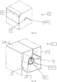
- the compacting apparatus 1 comprises a filling opening 3 for filling waste material into a filling chamber 2 of the compacting machine 1.
- the filling opening 3 is closed with a door 40 which in the figures is a front hinged door.
- the door 40 could also be a sliding door or a drum, which empties into the filling chamber 2 by tilting the drum.
- Below the filling chamber 2 is the compression chamber 4 placed with an inner surface comprising a front wall 5 and an opposite rear wall 6 and side walls 38 which together with the front wall 5 and the rear wall 6 provides a closed space.
- the inner surface of the compression chamber 4 is formed as a uniformly arcuate/curved channel.
- the arcuate front wall 5 and the rear wall 6 form this; in this example, they are concentric formed with each other.
- the rear wall 6 could also be a plan wall but in this case, the front 5 and rear wall 6 are both curved formed as a cylinder 26 forms the rear wall 5.
- the front wall 5 is a segment of a circle arc.
- the arcuate front wall 5 is placed with a radius R from a centre and the rear wall 6 is placed with a distance r from the centre. R is larger than r.
- the centre coincides with the centreline of the cylinder 26.
- the door 40 closing the filling opening 3 is at the inner side formed with the same arc angle as the front wall 5, thereby extending the compression chamber when the door is closed.
- a press plunger 7 is adapted to follow the arcuate compression chamber 4 following and substantially touching the entire inner surface of the arcuate front wall 5 when the press plunger 7 is moved inside the compression chamber 4 from an upper position to a lower position (and conversely).
- the press plunger 7 is pivotally arranged around an axis of rotation 18 placed outside the compression chamber 4 in the middle of the compacting apparatus 1.
- the axis of rotation 18 is the centreline of the cylinder.
- the press plunger 7 is fastened immovably to an outside wall 28 of the cylinder 26.
- the axis of rotating 18 is the pivotal centre for the press plunger 7 and the centre C for the radius r and the radius R.
- the sidewalls 38 of the compression chamber 4 are advantageously plane.
- the press plunger 7 is moved by a power supply 14. This could be a rotating electrical motor. In this example, it is a handle 52 to be moved manually.
- the press plunger 7 comprises a first surface 8 placed opposite a second surface 9.
- the second surface 9
- FIG. 2A shows the press plunger 7 in the upper position before the waste material has been compressed.
- Fig 2B shows the press plunger 7 in the lower position where the waste material has been compressed.
- the plunger 7 presses the compressed material into an output module 31.
- the output module 31 is releasable attached to the compacting apparatus 1 at an outlet opening 13 of the compression chamber 4 by releasable fastening means (not shown). When the output module 31 is filled with compressed waste, the filling process is over. A sensor may detect this, and the output module 31 may now be released from the compacting apparatus 1.
- the press plunger 7 moves in a curved manner and has a large moving angle.
- the press plunger 7 moves on a circular arc.
- the movement in this example being more than 180o. It can move up to around 270o.
- the door 40 that closes the filling chamber 2 may also be curved at the inside surface 41.
- the curving of the inside surface 41 is the same as for the front wall 5 of the compression chamber 4.
- the device may be constructed with or without the output module 31.
- the output module 31 may be fastened to the compacting machine 1 by a snap lock device.
- the output module 31 is firmly and sealed connected to the compression apparatus 1.
- the output module may also be a bin as shown in fig 9 .
- the hinged door 40 - fig. 1-2B - closes the filling chamber 2 when the compacting apparatus is to be used.
- the handle 52 is moved and by the rotation of the horizontal axis 18, the press plunger 7 moves from the first position to the second position whereby the waste material is compressed.
- the compressed waste material is removed from the machine during an opening. In this opening, the replaceable output module 31 may be placed, or a closing door can simply close it.
- the press plunger 7 in the lower position may be substantially parallel to the vertical plane or may have an angle of around 90o. In the upper position/first position, the angle between the second surface of the press plunger 7 and vertical plane is around zero or may have an angle of around 90o.
- the press plunger may have a moving angle of nearly 360o.
- FIG. 2C-H shows different situations for the first embodiment of the compacting apparatus.
- the door 40 is open into the filling chamber 2
- the door 40 is closed and the press plunger 7 in the first position ready for pressing towards the waste material placed in the filling chamber 2.
- the press plunger 7 has compressed the waste material and is moving it towards an outlet and output module 31.
- Fig, 2F and G show the first embodiment placed on a tabletop making it easier to remove the compressed waste material.
- Fig 2H is a perspective view of the first embodiment.
- FIG. 3A-B differs from fig. 1 and 2A-H by placing the filling opening 3 at the top of the device.
- the filling opening 3 is placed in the front.
- the reference numbers of the figures represent the same technical elements, as is the case in fig 1 and fig. 2A-H .
- the power supply 14 in fig. 1-3B is a manually operated handle 52.
- the handle 52 drives the cylinder 26.
- a tooth wheel 36 is advantageously placed interacting with teeth 37 placed at an inside surface of the cylinder 26.
- the outside surface 28 of the cylinder 26 comprises the rear wall 6 of the compression chamber 4.
- the inner surface of the compression chamber 4 is shaped as a uniformly arcuate channel. It comprises the arcuate front wall 5 and the rear wall 6.
- the arcuate front wall 5 is placed with a radius R from the centre 18 and the arcuate rear wall 6 is placed with a radius r from the centre.
- R is typically 240 mm. and r is typically 75 mm.
- the centre is the axis of rotation 18.
- the press plunger 7 is immovably attached to the outside surface 28 of the cylinder 26 and follows the arcuate front wall 5 when moved. It substantially touches the entire inner surface of the front wall 5 and the sidewalls of the compression chamber 4 with a circumferential edge when the press plunger 7 is moved inside the compression chamber 4.
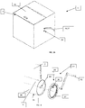
- Fig 5 is perspective x-ray view of a second embodiment of a compacting apparatus 1 according to the present invention suitable for compressing household waste material.
- the power supply 14 is an electrical motor 54.
- FIG. 6 shows the second embodiment in perspective view.
- the filling opening is placed in the front.
- the power supply for the second embodiment is an electrical motor 54.
- Fig 7 is a gear 34 construction suitable for the power supply being an electrical motor 54.
- the gear construction 34 is in principle the same as explained with reference to fig. 4 .
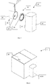
- FIG. 8 is a third embodiment shown in perspective view and with a filling opening and closing door 40 placed at the top. The placement of the filling opening is the main difference between this embodiment and the embodiment shown in fig. 5 and 6 .
- FIG. 9 is the same embodiment of the compacting apparatus 1 shown in fig. 5-6 but placed on the top of a bin 53.
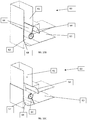
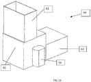
- FIG. 10 A-C shows an inlet module 60 that may be releasable coupled to the filling opening 3.
- the waste material is put into the inlet module 60.
- the inlet module 60 transports the waste material to the filling opening 3.
- the inlet module 60 comprises an inlet part 61, a transport chamber 62 and an outlet part 63.
- the transport chamber 62 comprises at least one pivotally arranged transport plunger 64 for transporting the waste material.
- the transport chamber 62 comprises an arcuate front wall 68 and an opposite rear wall 67 and sidewalls. It further comprises a power supply for moving the transport plunger 64.
- the transport plunger 64 is connected to the rear wall 67 and the rear wall 67 is pivotally arranged about an axis of rotation 66.
- the rear wall 67 is the outside of a cylinder arranged rotatable around the axis of rotation 66.
- the plunger 64 is adapted to be moved on a circle arc, and follows and touches the curvature of the arcuate front wall 68.
- the input module 60 is in principle built and designed as the compacting machine 1.
- the transport plunger 64 may comprise several plates 65 arranged around the axis of rotation 66. This is shown in fig 11A-B comprising 4 transport plates 65.
- the power for driving the transport plunger is typically an electrical motor 54 as shown in fig 12 .
- the motor ⁇ 54 is typically engaged with the transport plunger 64 in the same way as explained with reference to fig. 1-9 .
- the transport plunger is adapted ⁇ to be moved 360o * n, n > 0.
- the compacting apparatus no matter which embodiment - presses waste material in a curved movement.
- the press plunger 7 starts above the filling opening and moves down when the filling opening is closed safely. Through the downward movement of the press plunger 7, the material is pressed into the output module 31 on the backside of the machine. If there is no output module 31 the waste material is just pressed into an output part of the compressing machine 1 where it may be emptied. This output part may be lined inside with a plastic bag in which the compacted waste material is collected
- power supply Small machines are driven manual by a handle and the power is transmitted through gear wheels. The power may also be supplied by an electric motor.
- the transmission can be either direct by a linear motor or indirect by a rotating motor with a gearbox.
- the compression apparatus 1 will be available in different sizes and follows a concept of modularity; especially the output module 31 is designed to be changed easily. Therefore fastening means are formed after the same concept no matter which output module 31 is chosen in order to fasten the output module 31 easy to the compacting apparatus 1. Unlike other waste compactors, this machine does not need a separate sheet to cover the piston during its movement. This function is realized by the filling part. When the filling part is closed, it is flush with the arcuate front wall and forms an arcuate front wall. Together the filling part and the compression chamber form a large pressing channel. Further, the compactor has a large filling chamber due to the piston's moving angle. The waste material can be filled directly into the compaction chamber, because the piston moves up above the filling opening. Therefore, the filling chamber and the compaction chamber are practically the same and the whole space between the output module and the upper position of the piston can be seen as a large filling chamber.
- Smaller machines especially these for being used in a kitchen comprises a power transmission such as:
- the door 40 may be constructed in different ways Through a top hinged door. Through a sliding door. A drum, which empties into the pressing chamber through tilting it. A tipping device, which lifts bins or boxes and empties them into the opening. Through a conveyor belt. It has to stop while the piston is not in upper position or there has to be a separate pre-filling chamber. The door 40 may also be excluded if the filling opening is directly connected to an input module.
- the output modules 31 may be designed in different ways:
Landscapes
- Engineering & Computer Science (AREA)
- Mechanical Engineering (AREA)
- Processing Of Solid Wastes (AREA)
- Refuse Collection And Transfer (AREA)
Applications Claiming Priority (1)
| Application Number | Priority Date | Filing Date | Title |
|---|---|---|---|
| DKPA201700154A DK179462B1 (en) | 2017-03-06 | 2017-03-06 | Compacting apparatus and method for compressing waste material, and use of the compacting apparatus and the method for compressing household trash, garbage and waste material. |
Publications (1)
| Publication Number | Publication Date |
|---|---|
| EP3378637A1 true EP3378637A1 (de) | 2018-09-26 |
Family
ID=61569117
Family Applications (1)
| Application Number | Title | Priority Date | Filing Date |
|---|---|---|---|
| EP18160018.0A Withdrawn EP3378637A1 (de) | 2017-03-06 | 2018-03-05 | Verdichtungsvorrichtung und -verfahren zur komprimierung von abfallmaterial und verwendung von verdichtungsvorrichtung und -verfahren zur komprimierung von hausmüll, abfall und abfallmaterial |
Country Status (2)
| Country | Link |
|---|---|
| EP (1) | EP3378637A1 (de) |
| DK (1) | DK179462B1 (de) |
Cited By (2)
| Publication number | Priority date | Publication date | Assignee | Title |
|---|---|---|---|---|
| CN114239918A (zh) * | 2021-11-19 | 2022-03-25 | 哈尔滨工业大学 | 基于e2sfca可达分析的移动式压缩装备巡逻寻优方法 |
| WO2023284928A1 (en) * | 2021-07-16 | 2023-01-19 | Shark Containers A/S | A hydraulic arrangement and a compactor with a hydraulic arrangement |
Citations (10)
| Publication number | Priority date | Publication date | Assignee | Title |
|---|---|---|---|---|
| US3134321A (en) * | 1963-02-07 | 1964-05-26 | Sperry Rand Corp | Hay baler |
| DE2030914A1 (de) * | 1970-06-23 | 1971-12-30 | Demag Ag, 4100 Duisburg | Vorrichtung zum Pressen von losem, schüttfähigem Gut, insbesondere Müll |
| US4155297A (en) | 1977-03-14 | 1979-05-22 | Sargent Industries, Inc. | Self-packing container |
| GB2221405A (en) * | 1988-07-01 | 1990-02-07 | Parolisi Massimo | Improved waste disposal system |
| US5115735A (en) | 1989-06-23 | 1992-05-26 | Amp Incorporated | Press with control circuit arrangement |
| DE4202932A1 (de) * | 1992-02-01 | 1993-08-05 | Heinz Bergmann | Abfallverdichter |
| US5307607A (en) * | 1992-10-13 | 1994-05-03 | Frank Tondo | Apparatus for compacting trash or the like |
| EP0686493A1 (de) | 1994-05-26 | 1995-12-13 | LELY WELGER Maschinenfabrik GmbH | Schwingkolbenpresse |
| CN201228153Y (zh) * | 2008-03-21 | 2009-04-29 | 上海海事大学 | 全封闭自动压缩式垃圾箱 |
| CN103359434A (zh) * | 2013-06-28 | 2013-10-23 | 浙江工业大学 | 垃圾桶 |
-
2017
- 2017-03-06 DK DKPA201700154A patent/DK179462B1/en not_active IP Right Cessation
-
2018
- 2018-03-05 EP EP18160018.0A patent/EP3378637A1/de not_active Withdrawn
Patent Citations (10)
| Publication number | Priority date | Publication date | Assignee | Title |
|---|---|---|---|---|
| US3134321A (en) * | 1963-02-07 | 1964-05-26 | Sperry Rand Corp | Hay baler |
| DE2030914A1 (de) * | 1970-06-23 | 1971-12-30 | Demag Ag, 4100 Duisburg | Vorrichtung zum Pressen von losem, schüttfähigem Gut, insbesondere Müll |
| US4155297A (en) | 1977-03-14 | 1979-05-22 | Sargent Industries, Inc. | Self-packing container |
| GB2221405A (en) * | 1988-07-01 | 1990-02-07 | Parolisi Massimo | Improved waste disposal system |
| US5115735A (en) | 1989-06-23 | 1992-05-26 | Amp Incorporated | Press with control circuit arrangement |
| DE4202932A1 (de) * | 1992-02-01 | 1993-08-05 | Heinz Bergmann | Abfallverdichter |
| US5307607A (en) * | 1992-10-13 | 1994-05-03 | Frank Tondo | Apparatus for compacting trash or the like |
| EP0686493A1 (de) | 1994-05-26 | 1995-12-13 | LELY WELGER Maschinenfabrik GmbH | Schwingkolbenpresse |
| CN201228153Y (zh) * | 2008-03-21 | 2009-04-29 | 上海海事大学 | 全封闭自动压缩式垃圾箱 |
| CN103359434A (zh) * | 2013-06-28 | 2013-10-23 | 浙江工业大学 | 垃圾桶 |
Cited By (3)
| Publication number | Priority date | Publication date | Assignee | Title |
|---|---|---|---|---|
| WO2023284928A1 (en) * | 2021-07-16 | 2023-01-19 | Shark Containers A/S | A hydraulic arrangement and a compactor with a hydraulic arrangement |
| CN114239918A (zh) * | 2021-11-19 | 2022-03-25 | 哈尔滨工业大学 | 基于e2sfca可达分析的移动式压缩装备巡逻寻优方法 |
| CN114239918B (zh) * | 2021-11-19 | 2022-05-24 | 哈尔滨工业大学 | 基于e2sfca可达分析的移动式压缩装备巡逻寻优方法 |
Also Published As
| Publication number | Publication date |
|---|---|
| DK201700154A1 (en) | 2018-11-13 |
| DK179462B1 (en) | 2018-11-14 |
Similar Documents
| Publication | Publication Date | Title |
|---|---|---|
| US7237480B2 (en) | Manually operated trash compactor | |
| RU2455167C2 (ru) | Пресс с загрузочным устройством и устройство для открывания и опорожнения прессуемых предметов | |
| US8001887B2 (en) | Universal manual trash compactor | |
| EP3378637A1 (de) | Verdichtungsvorrichtung und -verfahren zur komprimierung von abfallmaterial und verwendung von verdichtungsvorrichtung und -verfahren zur komprimierung von hausmüll, abfall und abfallmaterial | |
| CN104803133A (zh) | 智能垃圾桶压缩打包方法及装置 | |
| EP1601591B1 (de) | Sammel-, verdichtungs- und einbeutelvorrichtung für abfall im allgemeinen | |
| US3807299A (en) | Trash compactor with removable liner | |
| GB2447612A (en) | A waste compactor | |
| CN216995992U (zh) | 一种垃圾桶垃圾压紧装置 | |
| WO2008038317A1 (en) | Waste bin compacting mechanism for domestic refuse | |
| EP3381671B1 (de) | Verdichtungsvorrichtung und verfahren zum verdichten von abfallmaterial und verwendung der verdichtungsvorrichtung zur durchführung des verfahrens | |
| NO336731B1 (no) | Komprimeringsanordning | |
| US20050217511A1 (en) | Manually operated trash compactor | |
| WO1994027810A1 (en) | Compactor | |
| US3734008A (en) | Arrangement in receptacles for receiving materials,particularly refuse | |
| KR20160070043A (ko) | 쓰레기압축기 | |
| CN205499983U (zh) | 一种具有进料切断功能的垃圾压缩机 | |
| CN111204498B (zh) | 一种物料打包装置及方法 | |
| CN217189756U (zh) | 一种基于废钢回收称重粉碎设备 | |
| CN210646561U (zh) | 一种纸托盘边角废料回收压实装置 | |
| CN108525802A (zh) | 一种碎纸机 | |
| CN211443674U (zh) | 一种方便套接垃圾袋的垃圾箱 | |
| CN200961046Y (zh) | 提斗刮压式垃圾收集机 | |
| GB2435810A (en) | Waste compactor | |
| CN218705816U (zh) | 一种新型塑料垃圾桶 |
Legal Events
| Date | Code | Title | Description |
|---|---|---|---|
| PUAI | Public reference made under article 153(3) epc to a published international application that has entered the european phase |
Free format text: ORIGINAL CODE: 0009012 |
|
| STAA | Information on the status of an ep patent application or granted ep patent |
Free format text: STATUS: THE APPLICATION HAS BEEN PUBLISHED |
|
| AK | Designated contracting states |
Kind code of ref document: A1 Designated state(s): AL AT BE BG CH CY CZ DE DK EE ES FI FR GB GR HR HU IE IS IT LI LT LU LV MC MK MT NL NO PL PT RO RS SE SI SK SM TR |
|
| AX | Request for extension of the european patent |
Extension state: BA ME |
|
| STAA | Information on the status of an ep patent application or granted ep patent |
Free format text: STATUS: REQUEST FOR EXAMINATION WAS MADE |
|
| 17P | Request for examination filed |
Effective date: 20190312 |
|
| RBV | Designated contracting states (corrected) |
Designated state(s): AL AT BE BG CH CY CZ DE DK EE ES FI FR GB GR HR HU IE IS IT LI LT LU LV MC MK MT NL NO PL PT RO RS SE SI SK SM TR |
|
| STAA | Information on the status of an ep patent application or granted ep patent |
Free format text: STATUS: EXAMINATION IS IN PROGRESS |
|
| 17Q | First examination report despatched |
Effective date: 20220412 |
|
| GRAP | Despatch of communication of intention to grant a patent |
Free format text: ORIGINAL CODE: EPIDOSNIGR1 |
|
| STAA | Information on the status of an ep patent application or granted ep patent |
Free format text: STATUS: GRANT OF PATENT IS INTENDED |
|
| INTG | Intention to grant announced |
Effective date: 20230922 |
|
| STAA | Information on the status of an ep patent application or granted ep patent |
Free format text: STATUS: THE APPLICATION IS DEEMED TO BE WITHDRAWN |
|
| 18D | Application deemed to be withdrawn |
Effective date: 20240203 |