EP0686493A1 - Schwingkolbenpresse - Google Patents
Schwingkolbenpresse Download PDFInfo
- Publication number
- EP0686493A1 EP0686493A1 EP95102309A EP95102309A EP0686493A1 EP 0686493 A1 EP0686493 A1 EP 0686493A1 EP 95102309 A EP95102309 A EP 95102309A EP 95102309 A EP95102309 A EP 95102309A EP 0686493 A1 EP0686493 A1 EP 0686493A1
- Authority
- EP
- European Patent Office
- Prior art keywords
- piston
- press
- cylinder
- channel
- plunger
- Prior art date
- Legal status (The legal status is an assumption and is not a legal conclusion. Google has not performed a legal analysis and makes no representation as to the accuracy of the status listed.)
- Granted
Links
Images
Classifications
-
- B—PERFORMING OPERATIONS; TRANSPORTING
- B30—PRESSES
- B30B—PRESSES IN GENERAL
- B30B9/00—Presses specially adapted for particular purposes
- B30B9/30—Presses specially adapted for particular purposes for baling; Compression boxes therefor
- B30B9/3082—Presses specially adapted for particular purposes for baling; Compression boxes therefor with compression means other than rams performing a rectilinear movement
-
- B—PERFORMING OPERATIONS; TRANSPORTING
- B30—PRESSES
- B30B—PRESSES IN GENERAL
- B30B9/00—Presses specially adapted for particular purposes
- B30B9/30—Presses specially adapted for particular purposes for baling; Compression boxes therefor
- B30B9/3057—Fluid-driven presses
Definitions
- the innovation relates to a vibrating piston press with an arc-shaped press channel, in which a press piston arranged to oscillate about an axis is moved back and forth by means of a hydraulic piston-cylinder unit, the piston rod of which is articulated on the press piston, while the cylinder of which is pivotally mounted on the press channel.
- a hydraulically driven press piston can be pivoted about a vertical axis.
- the material should be fed in by hand from above.
- the piston-cylinder unit is articulated on the press channel and the press piston in such a way that the effective lever arm length between the piston pin and the piston oscillation axis remains essentially unchanged during the press stroke. Because of this design, only relatively low compression densities can be achieved with a given power requirement.
- the cylinder arrangement requires a relatively large dimensioning of the baling chamber housing. It is also disadvantageous that the feed is to be carried out directly into the baling channel by hand, which entails the risk of accidents, allows only low throughputs and no longer meets today's comfort requirements.
- a mechanically driven vibrating piston press provided with a positive feed device is known from DE-OS 39 19 434.
- the disadvantage here is above all the relatively high construction costs, in particular in the case of the main transmission, when the press channel cross sections are approximately 1 square meter, as has been required recently.
- the innovation is based on the task of developing a vibrating piston press in such a way that, with a compact design of the press, also large-volume cardboard boxes and others Bulky goods with better use of power than before processed quickly.
- the piston rod is subjected to tension during the press stroke movements of the press piston and in its extended position includes an acute angle with the connecting line between the press piston pivot axis and the pin.
- the plunger moves slowly into the end position and can exert high pressing forces despite the relatively low drive power, while the plunger moves faster on its return stroke and thereby releases the filling opening longer, so that even larger cardboard boxes can be processed safely.
- the design as a traction piston results in a very space-saving design of the vibrating piston press.
- a preferred embodiment of the invention is that the piston-cylinder unit is double-acting and that for the return stroke of the plunger, both cylinder spaces are acted upon by a common oil line.
- the return stroke speed of the plunger can be increased despite the low oil flow, so that the filler opening is open for loading as long as possible.
- a favorable construction is achieved in that both cylinder spaces are connected to one another via a connecting line, and in that a controllable shut-off valve is arranged in the connecting line, which interrupts the circulation connection between the two cylinder spaces during the application of the cylinder chamber on the piston rod side.
- the further embodiment provides that the plunger can be swiveled about a horizontal axis located below the press channel and interacts with a feed device which, in time relation to the plunger, conveys the material supplied via a feed table through a filling opening into the press channel. This results in a compact size of the press, which can be transported to the installation site in the existing elevators of the department stores without major disassembly.
- a baling chamber housing 1 is built on support feet 2 and has a rectilinear baling channel section 3 and an arch-shaped baling channel section 4, in which a baling piston 6, which is mounted to oscillate about a horizontal axis 5, moves back and forth between an upper position 7 drawn in solid lines, and one lower position, drawn in dash-dot lines 8.
- the upper wall 9 of the press channel section 4 has a filling opening 10, which is preceded by a feed space 11.
- the plunger 6 completely releases the filling opening 10 in its lower position 8.
- the feed space 11 is formed by a feed table 12 which extends between two side walls 13 and opens into the press channel section 4 at a distance above the lower position 8 of the plunger 6.
- a conveyor belt 15 rotating uniformly in the direction of arrow 14 is arranged in the feed table 12.
- the transition from Conveyor belt 15 to the filling opening 10 is carried out by a roller and a fixed platform 16, which ends shortly before the movement path of the plunger 6 with a bend and forms the lower edge of the filling opening 10.
- a feed device 18 is arranged above the filling opening 10 and is driven in a temporal relationship to the plunger 6.
- the plunger 6 is driven by two piston-cylinder units 19; one is arranged outside the side wall 13.
- a piston rod 20 is in each case pivotally mounted on a bolt 22 which is welded to the side of the plunger 6 and which extends outwards through an elongated slot 21 in the side wall 13, while the cylinder 23 is mounted on a cross member fastened to the compression channel 3 by means of a pin 24.
- the arrangement is designed so that the piston rod 20 is retracted into the cylinder 23 in the upper position 7 drawn in solid lines of the plunger 6 and in the lower position 8 of the plunger 6 with a connecting line 25 between axis 5 and pin 22 an acute angle X includes.
- the piston-cylinder unit 19 is double-acting and has an oil line 26 for acting on the piston rod-side cylinder space 27 (piston ring surface) and a second oil line 28 for acting on the piston-side cylinder space 29, which may serve as a return oil line. Both oil lines 26, 28 can also be coupled by a common oil line 30, which is shown in dashed lines, and pressurized oil can be applied at the same time. As a result, the oil from the cylinder chamber 27 on the piston rod side flows into the cylinder chamber 29 on the piston side, as a result of which the piston rod 20 retracts quickly despite the relatively small amount of oil flow.
- a hydraulic unit 32 is arranged below the feed table 12.
- the operating principle of the vibrating piston press is as follows: The plunger 6 is in the lower position 8, the piston rod 20 is extended. The conveyor belt 15 and the feed device 18 move in the direction of the arrows 14, 31 and push the cardboard waste to be pressed through the filling opening 10 into the press channel 3. After a predetermined number of strokes of the feed device 18, the oil line 26 is pressurized with oil. The plunger 6 moves from its lower position 8 to the upper position 7, oil flows from the cylinder chamber 29 into the oil line 28, which now serves as a return oil line.
- the plunger 6 Due to the angular assignment of the plunger pivot axis 5 and the articulation point 22 of the piston rod 20, the plunger 6 initially moves quickly with small forces, whereas where high press forces are required, the plunger 6 moves at low speed with the maximum effective lever arm length (upper press position 7). After reaching the upper position 7 of the plunger 6, the oil line 30 is supplied with pressurized oil, so that both cylinder spaces 27, 29 are acted upon and the plunger 6 is quickly returned to its lower position 8. A new filling cycle begins. When the bale length is reached, the bale is tied in a manner known per se.
Landscapes
- Engineering & Computer Science (AREA)
- Mechanical Engineering (AREA)
- Press Drives And Press Lines (AREA)
- Toys (AREA)
- Processing Of Solid Wastes (AREA)
Abstract
Description
- Die Neuerung betrifft eine Schwingkolbenpresse mit einem bogenförmig verlaufenden Preßkanal, in dem ein um eine Achse schwingbar angeordneter Preßkolben mittels einer hydraulischen Kolben-Zylindereinheit hin und her bewegt wird, deren Kolbenstange am Preßkolben angelenkt ist, während deren Zylinder schwenkbar am Preßkanal gelagert ist.
- Bei einer durch die DE-OS 22 44 037 bekannten Schwingkolbenpresse ist ein hydraulisch angetriebener Preßkolben um eine vertikale Achse schwingbar. Das Material soll von oben per Hand zugeführt werden. Die Kolben-Zylindereinheit ist so an Preßkanal und Preßkolben angelenkt, daß die wirksame Hebelarmlänge zwischen Kolbenbolzen und Kolbenschwingachse im wesentlichen während des Preßhubes unverändert bleibt. Aufgrund dieser Ausbildung lassen sich bei vorgegebenem Leistungsbedarf nur relativ geringe Preßdichten erzielen. Darüber hinaus erfordert die Zylinderanordnung eine relativ starke Dimensionierung des Preßraumgehäuses. Nachteilig ist auch, daß die Zuführung direkt in den Preßkanal von Hand erfolgen soll, was Unfallgefahren birgt, nur geringe Durchsätze erlaubt und den heutigen Komfortwünschen nicht mehr entspricht.
- Eine mit einer Zwangszuführeinrichtung versehene, mechanisch angetriebene Schwingkolbenpresse ist durch die DE-OS 39 19 434 bekannt. Nachteilig hierbei ist vor allem der relativ hohe Bauaufwand, insbesondere beim Hauptgetriebe, wenn die Preßkanalquerschnitte ca. 1 qm betragen, wie es in jüngster Zeit gefordert wird.
- Der Neuerung liegt die Aufgabe zugrunde, eine Schwingkolbenpresse so weiterzubilden, daß sich bei kompakter Bauform der Presse auch großvolumige Kartonagen und andere sperrige Güter mit besserer Kraftausnutzung als bisher zügig verarbeiten lassen.
- Die Neuerung wird erfindungsgemäß dadurch gelöst, daß die Kolbenstange bei Preßhubbewegungen des Preßkolbens auf Zug belastet ist und in ihrer ausgefahrenen Stellung mit der Verbindungslinie zwischen Preßkolbenschwenkachse und Bolzen einen spitzen Winkel einschließt. Durch diese Ausgestaltung bewegt sich der Preßkolben langsam in die Preßendposition und kann dadurch trotz relativ geringer Antriebsleistung hohe Preßkräfte ausüben, während sich der Preßkolben auf seinem Rückhub schneller bewegt und dadurch die Einfüllöffnung länger freigibt, so daß auch größere Kartonagen sicher verarbeitet werden. Darüber hinaus ergibt sich durch die Ausbildung als Zugkolben eine sehr raumsparende Bauform der Schwingkolbenpresse.
- Eine bevorzugte Ausführungsform der Erfindung besteht darin, daß die Kolben-Zylindereinheit doppelt wirkend ausgebildet ist und daß zum Rückhub des Preßkolbens beide Zylinderräume durch eine gemeinsame Ölleitung beaufschlagt werden. Auf diese einfache Weise läßt sich die Rückhubgeschwindigkeit des Preßkolbens trotz geringen Ölmengenstromes erhöhen, so daß die Einfüllöffnung möglichst lange zur Beschickung geöffnet ist.
- Eine günstige Konstruktion wird dadurch erreicht, daß beide Zylinderräume über eine Verbindungsleitung miteinander verbunden sind, und daß in der Verbindungsleitung ein steuerbares Absperrventil angeordnet ist, welches die Umlaufverbindung beider Zylinderräume während der Beaufschlagung des kolbenstangenseitigen Zylinderraumes unterbricht.
- Aufgrund der Verbindungsleitung beider Zylinderräume strömt das Öl bei hydraulischer Differentialbeaufschlagung der hydraulischen Kolben-Zylindereinheit direkt aus dem kolbenstangenseitigen Zylinderraum in den kolbenseitigen Zylinderraum. Auf diese Weise können trotz Verwendung von hydraulischen Kolben-Zylindereinheiten mit einem Verhältnis der Kolben zur Kolbenstangenfläche von 1:5, welches bei Einsatz als Zugkolben zweckmäßig ist, Rückströmverluste des Öls durch die ursprüngliche Zuleitung in den kolbenseitigen Zylinderraum vermieden werden.
- Die weitere Ausgestaltung sieht vor, daß der Preßkolben um eine horizontale, unterhalb des Preßkanales gelegene Achse schwingbar ist und mit einer Zuführeinrichtung zusammenwirkt, welche in zeitlicher Beziehung zum Preßkolben das über einen Aufgabetisch zugeführte Material durch eine Einfüllöffnung in den Preßkanal fördert. Hierdurch ergibt sich eine kompakte Baugröße der Presse, die ohne größere Demontage auch in den vorhandenen Aufzügen der Kaufhäuser zum Aufstellungsort zu befördern ist.
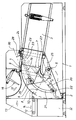
- In der Zeichnung ist eine Ausführungsform der Erfindung in schematischer Darstellung im Längsschnitt gezeigt.
- Ein Preßraumgehäuse 1 ist auf Tragfüßen 2 aufgebaut und besitzt einen geradlinigen Preßkanalabschnitt 3 und einen bogenförmig verlaufenden Preßkanalabschnitt 4, in dem sich ein um eine horizontale Achse 5 schwingbar gelagerter Preßkolben 6 hin und her bewegt zwischen einer oberen, in Vollinien gezeichneten Stellung 7, und einer unteren, in Strichpunktlinien gezeichneten Stellung 8.
- Die obere Wand 9 des Preßkanalabschnittes 4 weist eine Einfüllöffnung 10 auf, der ein Aufgaberaum 11 vorgeschaltet ist. Der Preßkolben 6 gibt die Einfüllöffnung 10 in seiner unteren Stellung 8 vollständig frei. Der Aufgaberaum 11 wird gebildet von einem Aufgabetisch 12, der sich zwischen zwei Seitenwänden 13 erstreckt und im Abstand oberhalb der unteren Stellung 8 des Preßkolbens 6 in den Preßkanalabschnitt 4 einmündet. In dem Aufgabetisch 12 ist ein gleichförmig in Richtung des Pfeiles 14 umlaufendes Förderband 15 angeordnet. Der Übergang vom Förderband 15 zur Einfüllöffnung 10 erfolgt durch eine Walze und eine feststehende Plattform 16, die kurz vor der Bewegungsbahn des Preßkolbens 6 mit einer Abkantung endet und die Unterkante der Einfüllöffnung 10 bildet. Oberhalb der Einfüllöffnung 10 ist eine Zuführeinrichtung 18 angeordnet, die in zeitlicher Beziehung zum Preßkolben 6 angetrieben ist.
- Der Antrieb des Preßkolbens 6 erfolgt durch zwei Kolben-Zylindereinheiten 19; jeweils eine ist außerhalb der Seitenwand 13 angeordnet. Eine Kolbenstange 20 ist jeweils an einem seitlich am Preßkolben 6 angeschweißten, sich durch einen Langlochschlitz 21 in der Seitenwand 13 nach außen erstreckenden Bolzen 22 schwenkbar gelagert, während der Zylinder 23 mittels eines Zapfens 24 an einem am Preßkanal 3 befestigten Querträger gelagert ist. Die Anordnung ist so ausgelegt, daß die Kolbenstange 20 in der oberen, in Vollinien gezeichneten Stellung 7 des Preßkolbens 6 in den Zylinder 23 eingefahren ist und in der unteren Stellung 8 des Preßkolbens 6 mit einer Verbindungslinie 25 zwischen Achse 5 und Bolzen 22 einen spitzen Winkel X einschließt. Die Kolben-Zylindereinheit 19 ist doppelt wirkend ausgebildet und weist eine Ölleitung 26 zur Beaufschlagung des kolbenstangenseitigen Zylinderraumes 27 (Kolbenringfläche) und eine zweite Ölleitung 28 zur Beaufschlagung des kolbenseitigen Zylinderraumes 29 auf, die ggf. als Rücklaufölleitung dient. Beide Ölleitungen 26, 28 können auch durch eine gemeinsame Ölleitung 30, die in Strichlinie dargestellt ist, gekoppelt und gleichzeitig mit Drucköl beaufschlagt werden. Das Öl aus dem kolbenstangenseitigen Zylinderraum 27 strömt dadurch in den kolbenseitigen Zylinderraum 29, wodurch die Kolbenstange 20 trotz relativ kleinen Ölmengenstromes schnell einfährt. Ein Hydraulik-Aggregat 32 ist unterhalb des Aufgabetisches 12 angeordnet.
- Die Arbeitsweise der Schwingkolbenpresse ist folgende:
Der Preßkolben 6 befindet sich in der unteren Stellung 8, die Kolbenstange 20 ist ausgefahren. Das Förderband 15 sowie die Zuführeinrichtung 18 bewegen sich in Richtung der Pfeile 14, 31 und schieben die zu pressenden Kartonagenabfälle durch die Einfüllöffnung 10 in den Preßkanal 3. Nach vorbestimmter Hubzahl der Zuführeinrichtung 18 wird die Ölleitung 26 mit Drucköl beaufschlagt. Der Preßkolben 6 bewegt sich aus seiner unteren Stellung 8 in die obere Stellung 7, dabei strömt Öl aus dem Zylinderraum 29 in die Ölleitung 28, die jetzt als Rücklaufölleitung dient. Aufgrund der Winkelzuordnung von Preßkolbenschwenkachse 5 und Anlenkpunkt 22 der Kolbenstange 20 bewegt sich der Preßkolben 6 zunächst bei kleinen Kräften schnell, während dort, wo hohe Preßkräfte notwendig sind, der Preßkolben 6 sich mit kleiner Geschwindigkeit bewegt bei maximal wirksamer Hebelarmlänge (obere Preßstellung 7). Nach Erreichen der oberen Stellung 7 des Preßkolbens 6 wird die Ölleitung 30 mit Drucköl versorgt, so daß beide Zylinderräume 27, 29 beaufschlagt werden und der Preßkolben 6 schnell in seine untere Stellung 8 zurückgefahren wird. Ein neuer Befüllzyklus beginnt. Bei erreichter Ballenlänge wird der Ballen in an sich bekannter Weise abgebunden.
Claims (4)
- Schwingkolbenpresse mit einem bogenförmig verlaufenden Preßkanal (4), in dem ein um eine Achse schwingbar angeordneter Preßkolben (6) mittels einer hydraulischen Kolben-Zylindereinheit (19) hin und her bewegt wird, deren Kolbenstange (20) am Preßkolben (6) angelenkt ist, während deren Zylinder (23) schwenkbar am Preßkanal (3) gelagert ist, dadurch gekennzeichnet, daß die Kolbenstange (20) bei Preßhubbewegungen des Preßkolbens (6) auf Zug belastet ist und in ihrer ausgefahrenen Stellung (8) mit der Verbindungslinie (25) zwischen Preßkolbenschwenkachse (5) und Bolzen (22) einen spitzen Winkel (X) einschließt.
- Schwingkolbenpresse nach Anspruch 1, dadurch gekennzeichnet, daß die Kolben-Zylindereinheit (19) doppelt wirkend ausgebildet ist und daß zum Rückhub des Preßkolbens (6) beide Zylinderräume (27, 29) durch eine gemeinsame Ölleitung (30) beaufschlagt werden.
- Schwingkolbenpresse nach Anspruch 2, dadurch gekennzeichnet, daß beide Zylinderräume (27, 29) über eine Verbindungsleitung miteinander verbunden sind, und daß in der Verbindungsleitung ein steuerbares Absperrventil angeordnet ist, welches die Umlaufverbindung beider Zylinderräume (27, 29) während der Beaufschlagung des kolbenstangenseitigen Zylinderraumes (27) unterbricht.
- Schwingkolbenpresse nach einem oder mehreren der Ansprüche 1 bis 3, dadurch gekennzeichnet, daß der Preßkolben (6) um eine horizontale, unterhalb des Preßkanales gelegene Achse (5) schwingbar ist und mit einer Zuführeinrichtung (18) zusammenwirkt, welche in zeitlicher Beziehung zum Preßkolben (6) das über einen Aufgabetisch (12) zugeführte Material durch eine Einfüllöffnung (10) in den Preßkanal (4) fördert.
Applications Claiming Priority (2)
| Application Number | Priority Date | Filing Date | Title |
|---|---|---|---|
| DE9408619U | 1994-05-26 | ||
| DE9408619U DE9408619U1 (de) | 1994-05-26 | 1994-05-26 | Schwingkolbenpresse |
Publications (2)
| Publication Number | Publication Date |
|---|---|
| EP0686493A1 true EP0686493A1 (de) | 1995-12-13 |
| EP0686493B1 EP0686493B1 (de) | 1998-12-30 |
Family
ID=6909113
Family Applications (1)
| Application Number | Title | Priority Date | Filing Date |
|---|---|---|---|
| EP95102309A Expired - Lifetime EP0686493B1 (de) | 1994-05-26 | 1995-02-18 | Schwingkolbenpresse |
Country Status (5)
| Country | Link |
|---|---|
| US (1) | US5586494A (de) |
| EP (1) | EP0686493B1 (de) |
| JP (1) | JPH08150497A (de) |
| AT (1) | ATE175151T1 (de) |
| DE (2) | DE9408619U1 (de) |
Cited By (3)
| Publication number | Priority date | Publication date | Assignee | Title |
|---|---|---|---|---|
| EP0931643A1 (de) * | 1998-01-26 | 1999-07-28 | LELY WELGER Maschinenfabrik GmbH | Ballenpresse, insbesondere für Kartonagenabfälle, Papier Folie und dgl. |
| EP3378637A1 (de) | 2017-03-06 | 2018-09-26 | Hansen, Prebeb From | Verdichtungsvorrichtung und -verfahren zur komprimierung von abfallmaterial und verwendung von verdichtungsvorrichtung und -verfahren zur komprimierung von hausmüll, abfall und abfallmaterial |
| EP3381671A1 (de) | 2017-03-06 | 2018-10-03 | Hansen, Prebeb From | Verdichtungsvorrichtung und verfahren zum verdichten von abfallmaterial und verwendung der verdichtungsvorrichtung zur durchführung des verfahrens |
Families Citing this family (1)
| Publication number | Priority date | Publication date | Assignee | Title |
|---|---|---|---|---|
| CN112078166B (zh) * | 2020-09-01 | 2022-04-19 | 浙江省农业科学院 | 一种香榧榨油装置 |
Citations (6)
| Publication number | Priority date | Publication date | Assignee | Title |
|---|---|---|---|---|
| GB423692A (en) * | 1933-12-02 | 1935-02-06 | August Claas | Improvements in and relating to harvesting devices for hay, straw and like crops |
| FR795913A (fr) * | 1935-03-20 | 1936-03-25 | Dispositif d'approvisionnement pour presses à paille | |
| FR1156243A (fr) * | 1955-09-03 | 1958-05-13 | Sperry Rand Corp | Perfectionnements relatifs aux presses à balles |
| DE2244037A1 (de) * | 1972-09-05 | 1974-03-28 | Kurt Smolka | Muellpresse |
| DE2300636A1 (de) * | 1973-01-08 | 1974-07-18 | Pfitzenmeier & Rau | Muellbehaelter |
| EP0402723A2 (de) * | 1989-06-14 | 1990-12-19 | GEBRÜDER WELGER GmbH & Co. KG | Schwingkolbenpresse |
Family Cites Families (6)
| Publication number | Priority date | Publication date | Assignee | Title |
|---|---|---|---|---|
| NL143509C (de) * | 1962-12-05 | |||
| US3215291A (en) * | 1964-04-14 | 1965-11-02 | Int Harvester Co | Cotton picker compactor |
| CH494177A (de) * | 1968-06-24 | 1970-07-31 | Ochsner & Cie Ag J | Abstellbarer Transportbehälter für loses Material, z.B. Kehricht |
| DE3722757A1 (de) * | 1986-11-25 | 1989-01-19 | Kloeckner Humboldt Deutz Ag | Grossballenpresse |
| US5029522A (en) * | 1990-01-24 | 1991-07-09 | Brisson David J | Compactor for recyclable waste materials |
| US5458058A (en) * | 1994-02-15 | 1995-10-17 | Western Waste Industries | Refuse packer assembly |
-
1994
- 1994-05-26 DE DE9408619U patent/DE9408619U1/de not_active Expired - Lifetime
-
1995
- 1995-02-18 EP EP95102309A patent/EP0686493B1/de not_active Expired - Lifetime
- 1995-02-18 DE DE59504663T patent/DE59504663D1/de not_active Expired - Lifetime
- 1995-02-18 AT AT95102309T patent/ATE175151T1/de not_active IP Right Cessation
- 1995-05-25 JP JP7126758A patent/JPH08150497A/ja active Pending
- 1995-05-26 US US08/451,578 patent/US5586494A/en not_active Expired - Lifetime
Patent Citations (6)
| Publication number | Priority date | Publication date | Assignee | Title |
|---|---|---|---|---|
| GB423692A (en) * | 1933-12-02 | 1935-02-06 | August Claas | Improvements in and relating to harvesting devices for hay, straw and like crops |
| FR795913A (fr) * | 1935-03-20 | 1936-03-25 | Dispositif d'approvisionnement pour presses à paille | |
| FR1156243A (fr) * | 1955-09-03 | 1958-05-13 | Sperry Rand Corp | Perfectionnements relatifs aux presses à balles |
| DE2244037A1 (de) * | 1972-09-05 | 1974-03-28 | Kurt Smolka | Muellpresse |
| DE2300636A1 (de) * | 1973-01-08 | 1974-07-18 | Pfitzenmeier & Rau | Muellbehaelter |
| EP0402723A2 (de) * | 1989-06-14 | 1990-12-19 | GEBRÜDER WELGER GmbH & Co. KG | Schwingkolbenpresse |
Cited By (3)
| Publication number | Priority date | Publication date | Assignee | Title |
|---|---|---|---|---|
| EP0931643A1 (de) * | 1998-01-26 | 1999-07-28 | LELY WELGER Maschinenfabrik GmbH | Ballenpresse, insbesondere für Kartonagenabfälle, Papier Folie und dgl. |
| EP3378637A1 (de) | 2017-03-06 | 2018-09-26 | Hansen, Prebeb From | Verdichtungsvorrichtung und -verfahren zur komprimierung von abfallmaterial und verwendung von verdichtungsvorrichtung und -verfahren zur komprimierung von hausmüll, abfall und abfallmaterial |
| EP3381671A1 (de) | 2017-03-06 | 2018-10-03 | Hansen, Prebeb From | Verdichtungsvorrichtung und verfahren zum verdichten von abfallmaterial und verwendung der verdichtungsvorrichtung zur durchführung des verfahrens |
Also Published As
| Publication number | Publication date |
|---|---|
| US5586494A (en) | 1996-12-24 |
| DE59504663D1 (de) | 1999-02-11 |
| JPH08150497A (ja) | 1996-06-11 |
| DE9408619U1 (de) | 1995-06-22 |
| ATE175151T1 (de) | 1999-01-15 |
| EP0686493B1 (de) | 1998-12-30 |
Similar Documents
| Publication | Publication Date | Title |
|---|---|---|
| DE69509693T2 (de) | Apparat mit einander gegenüberliegenden Zylindern für die Betätigung des stabes eines Andruckelements in Mischer des internen Typus | |
| DE2602845C2 (de) | Presse zum Auspressen von Flüssigkeit | |
| DE102007013382A1 (de) | Verfahren zum Herstellen eines Pressballens und Vorrichtung zum Herstellen von Pressballen | |
| DE2344698C2 (de) | Vorrichtung zum Verdichten von Müll | |
| DE2014591A1 (de) | Ballenpresse | |
| EP4069504B1 (de) | Ballenpresse sowie verfahren zum betreiben der ballenpresse | |
| EP0686493A1 (de) | Schwingkolbenpresse | |
| DE10145690A1 (de) | Ballenpresse | |
| DE2523969C2 (de) | Ballenpresse, insbesondere für faseriges Gut | |
| DE2254641C3 (de) | Müllverladevorrichtung | |
| EP1285572A1 (de) | Ballenpresse | |
| DE102008061339A1 (de) | Dosiervorrichtung für Schüttgüter mit unterschiedlicher Fließfähigkeit | |
| DE2252298C3 (de) | Gerät zum Formen eines Stapels aus halm- oder blattförmigem Erntegut | |
| DE1189922B (de) | Hublader mit teleskopischem Zentralmast | |
| DE2308232C3 (de) | Ballenpresse zum Verpressen von Altmaterial | |
| DE10139450A1 (de) | Ballenpresse | |
| DE2171C (de) | Presse für Heu, Stroh oder Baumwolle mit Göpelbetrieb, wobei ein verdichteter Ballen den nachgiebigen Widerstand für jede neue Pressung bildet | |
| EP0931643B1 (de) | Ballenpresse, insbesondere für Kartonagenabfälle, Papier Folie und dgl. | |
| DE203105C (de) | ||
| DE2438494A1 (de) | Presse zum spanlosen umformen von blech o.dgl. | |
| DE1580959A1 (de) | Klappenverschlussgetriebe fuer Sattelboden-Selbstentladewagen | |
| DE924136C (de) | Muellwagen mit Druckplatte | |
| DE1938602C3 (de) | Ballenpresse für faseriges Gut | |
| DE3637C (de) | Maschine zum Pressen und Packen von Heu, Schafwolle, Baumwolle, Rofshaar und anderen ähnlichen Materialien | |
| DE381311C (de) | Maschine zum Buendeln des Futtergetreides, bei welcher das letztere in einer laenglichen, einen schwingenden Boden enthaltenden Mulde gepresst wird |
Legal Events
| Date | Code | Title | Description |
|---|---|---|---|
| PUAI | Public reference made under article 153(3) epc to a published international application that has entered the european phase |
Free format text: ORIGINAL CODE: 0009012 |
|
| AK | Designated contracting states |
Kind code of ref document: A1 Designated state(s): AT CH DE FR GB IT LI NL |
|
| 17P | Request for examination filed |
Effective date: 19960613 |
|
| GRAG | Despatch of communication of intention to grant |
Free format text: ORIGINAL CODE: EPIDOS AGRA |
|
| GRAG | Despatch of communication of intention to grant |
Free format text: ORIGINAL CODE: EPIDOS AGRA |
|
| GRAG | Despatch of communication of intention to grant |
Free format text: ORIGINAL CODE: EPIDOS AGRA |
|
| GRAH | Despatch of communication of intention to grant a patent |
Free format text: ORIGINAL CODE: EPIDOS IGRA |
|
| 17Q | First examination report despatched |
Effective date: 19980520 |
|
| GRAH | Despatch of communication of intention to grant a patent |
Free format text: ORIGINAL CODE: EPIDOS IGRA |
|
| GRAA | (expected) grant |
Free format text: ORIGINAL CODE: 0009210 |
|
| AK | Designated contracting states |
Kind code of ref document: B1 Designated state(s): AT CH DE FR GB IT LI NL |
|
| PG25 | Lapsed in a contracting state [announced via postgrant information from national office to epo] |
Ref country code: NL Free format text: LAPSE BECAUSE OF FAILURE TO SUBMIT A TRANSLATION OF THE DESCRIPTION OR TO PAY THE FEE WITHIN THE PRESCRIBED TIME-LIMIT Effective date: 19981230 Ref country code: IT Free format text: LAPSE BECAUSE OF FAILURE TO SUBMIT A TRANSLATION OF THE DESCRIPTION OR TO PAY THE FEE WITHIN THE PRE;WARNING: LAPSES OF ITALIAN PATENTS WITH EFFECTIVE DATE BEFORE 2007 MAY HAVE OCCURRED AT ANY TIME BEFORE 2007. THE CORRECT EFFECTIVE DATE MAY BE DIFFERENT FROM THE ONE RECORDED.SCRIBED TIME-LIMIT Effective date: 19981230 |
|
| REF | Corresponds to: |
Ref document number: 175151 Country of ref document: AT Date of ref document: 19990115 Kind code of ref document: T |
|
| REG | Reference to a national code |
Ref country code: CH Ref legal event code: EP |
|
| REF | Corresponds to: |
Ref document number: 59504663 Country of ref document: DE Date of ref document: 19990211 |
|
| PG25 | Lapsed in a contracting state [announced via postgrant information from national office to epo] |
Ref country code: AT Free format text: LAPSE BECAUSE OF NON-PAYMENT OF DUE FEES Effective date: 19990218 |
|
| PG25 | Lapsed in a contracting state [announced via postgrant information from national office to epo] |
Ref country code: LI Free format text: LAPSE BECAUSE OF NON-PAYMENT OF DUE FEES Effective date: 19990228 Ref country code: CH Free format text: LAPSE BECAUSE OF NON-PAYMENT OF DUE FEES Effective date: 19990228 |
|
| GBT | Gb: translation of ep patent filed (gb section 77(6)(a)/1977) |
Effective date: 19990325 |
|
| ET | Fr: translation filed | ||
| NLV1 | Nl: lapsed or annulled due to failure to fulfill the requirements of art. 29p and 29m of the patents act | ||
| REG | Reference to a national code |
Ref country code: CH Ref legal event code: PL |
|
| PLBE | No opposition filed within time limit |
Free format text: ORIGINAL CODE: 0009261 |
|
| STAA | Information on the status of an ep patent application or granted ep patent |
Free format text: STATUS: NO OPPOSITION FILED WITHIN TIME LIMIT |
|
| 26N | No opposition filed | ||
| REG | Reference to a national code |
Ref country code: GB Ref legal event code: IF02 |
|
| PGFP | Annual fee paid to national office [announced via postgrant information from national office to epo] |
Ref country code: GB Payment date: 20130213 Year of fee payment: 19 Ref country code: DE Payment date: 20130220 Year of fee payment: 19 Ref country code: FR Payment date: 20130228 Year of fee payment: 19 |
|
| REG | Reference to a national code |
Ref country code: DE Ref legal event code: R081 Ref document number: 59504663 Country of ref document: DE Owner name: WELGER RECYCLING ENGINEERING GMBH, DE Free format text: FORMER OWNER: WELGER MASCHINENFABRIK GMBH, 38304 WOLFENBUETTEL, DE Effective date: 20140502 Ref country code: DE Ref legal event code: R081 Ref document number: 59504663 Country of ref document: DE Owner name: LELY VERMEER MASCHINENFABRIK GMBH, DE Free format text: FORMER OWNER: WELGER MASCHINENFABRIK GMBH, 38304 WOLFENBUETTEL, DE Effective date: 20140502 |
|
| REG | Reference to a national code |
Ref country code: DE Ref legal event code: R119 Ref document number: 59504663 Country of ref document: DE |
|
| REG | Reference to a national code |
Ref country code: DE Ref legal event code: R081 Ref document number: 59504663 Country of ref document: DE Owner name: WELGER RECYCLING ENGINEERING GMBH, DE Free format text: FORMER OWNER: LELY VERMEER MASCHINENFABRIK GMBH, 38304 WOLFENBUETTEL, DE Effective date: 20140902 |
|
| GBPC | Gb: european patent ceased through non-payment of renewal fee |
Effective date: 20140218 |
|
| REG | Reference to a national code |
Ref country code: FR Ref legal event code: ST Effective date: 20141031 |
|
| REG | Reference to a national code |
Ref country code: DE Ref legal event code: R119 Ref document number: 59504663 Country of ref document: DE Effective date: 20140902 |
|
| PG25 | Lapsed in a contracting state [announced via postgrant information from national office to epo] |
Ref country code: DE Free format text: LAPSE BECAUSE OF NON-PAYMENT OF DUE FEES Effective date: 20140902 Ref country code: GB Free format text: LAPSE BECAUSE OF NON-PAYMENT OF DUE FEES Effective date: 20140218 Ref country code: FR Free format text: LAPSE BECAUSE OF NON-PAYMENT OF DUE FEES Effective date: 20140228 |