EP3378733B1 - Appareil et procédé de commande d'angle de roue en fonction de la situation (had ou adas) - Google Patents
Appareil et procédé de commande d'angle de roue en fonction de la situation (had ou adas) Download PDFInfo
- Publication number
- EP3378733B1 EP3378733B1 EP17161795.4A EP17161795A EP3378733B1 EP 3378733 B1 EP3378733 B1 EP 3378733B1 EP 17161795 A EP17161795 A EP 17161795A EP 3378733 B1 EP3378733 B1 EP 3378733B1
- Authority
- EP
- European Patent Office
- Prior art keywords
- wheel angle
- controller
- road vehicle
- control loop
- internal state
- Prior art date
- Legal status (The legal status is an assumption and is not a legal conclusion. Google has not performed a legal analysis and makes no representation as to the accuracy of the status listed.)
- Active
Links
Images


Classifications
-
- B—PERFORMING OPERATIONS; TRANSPORTING
- B62—LAND VEHICLES FOR TRAVELLING OTHERWISE THAN ON RAILS
- B62D—MOTOR VEHICLES; TRAILERS
- B62D5/00—Power-assisted or power-driven steering
- B62D5/04—Power-assisted or power-driven steering electrical, e.g. using an electric servo-motor connected to, or forming part of, the steering gear
- B62D5/0457—Power-assisted or power-driven steering electrical, e.g. using an electric servo-motor connected to, or forming part of, the steering gear characterised by control features of the drive means as such
- B62D5/046—Controlling the motor
- B62D5/0463—Controlling the motor calculating assisting torque from the motor based on driver input
-
- B—PERFORMING OPERATIONS; TRANSPORTING
- B62—LAND VEHICLES FOR TRAVELLING OTHERWISE THAN ON RAILS
- B62D—MOTOR VEHICLES; TRAILERS
- B62D5/00—Power-assisted or power-driven steering
- B62D5/04—Power-assisted or power-driven steering electrical, e.g. using an electric servo-motor connected to, or forming part of, the steering gear
-
- B—PERFORMING OPERATIONS; TRANSPORTING
- B62—LAND VEHICLES FOR TRAVELLING OTHERWISE THAN ON RAILS
- B62D—MOTOR VEHICLES; TRAILERS
- B62D6/00—Arrangements for automatically controlling steering depending on driving conditions sensed and responded to, e.g. control circuits
- B62D6/002—Arrangements for automatically controlling steering depending on driving conditions sensed and responded to, e.g. control circuits computing target steering angles for front or rear wheels
-
- B—PERFORMING OPERATIONS; TRANSPORTING
- B60—VEHICLES IN GENERAL
- B60W—CONJOINT CONTROL OF VEHICLE SUB-UNITS OF DIFFERENT TYPE OR DIFFERENT FUNCTION; CONTROL SYSTEMS SPECIALLY ADAPTED FOR HYBRID VEHICLES; ROAD VEHICLE DRIVE CONTROL SYSTEMS FOR PURPOSES NOT RELATED TO THE CONTROL OF A PARTICULAR SUB-UNIT
- B60W10/00—Conjoint control of vehicle sub-units of different type or different function
- B60W10/20—Conjoint control of vehicle sub-units of different type or different function including control of steering systems
-
- B—PERFORMING OPERATIONS; TRANSPORTING
- B60—VEHICLES IN GENERAL
- B60W—CONJOINT CONTROL OF VEHICLE SUB-UNITS OF DIFFERENT TYPE OR DIFFERENT FUNCTION; CONTROL SYSTEMS SPECIALLY ADAPTED FOR HYBRID VEHICLES; ROAD VEHICLE DRIVE CONTROL SYSTEMS FOR PURPOSES NOT RELATED TO THE CONTROL OF A PARTICULAR SUB-UNIT
- B60W30/00—Purposes of road vehicle drive control systems not related to the control of a particular sub-unit, e.g. of systems using conjoint control of vehicle sub-units
- B60W30/14—Adaptive cruise control
-
- B—PERFORMING OPERATIONS; TRANSPORTING
- B62—LAND VEHICLES FOR TRAVELLING OTHERWISE THAN ON RAILS
- B62D—MOTOR VEHICLES; TRAILERS
- B62D15/00—Steering not otherwise provided for
- B62D15/02—Steering position indicators ; Steering position determination; Steering aids
- B62D15/025—Active steering aids, e.g. helping the driver by actively influencing the steering system after environment evaluation
-
- B—PERFORMING OPERATIONS; TRANSPORTING
- B62—LAND VEHICLES FOR TRAVELLING OTHERWISE THAN ON RAILS
- B62D—MOTOR VEHICLES; TRAILERS
- B62D5/00—Power-assisted or power-driven steering
- B62D5/04—Power-assisted or power-driven steering electrical, e.g. using an electric servo-motor connected to, or forming part of, the steering gear
- B62D5/0457—Power-assisted or power-driven steering electrical, e.g. using an electric servo-motor connected to, or forming part of, the steering gear characterised by control features of the drive means as such
- B62D5/046—Controlling the motor
-
- B—PERFORMING OPERATIONS; TRANSPORTING
- B62—LAND VEHICLES FOR TRAVELLING OTHERWISE THAN ON RAILS
- B62D—MOTOR VEHICLES; TRAILERS
- B62D6/00—Arrangements for automatically controlling steering depending on driving conditions sensed and responded to, e.g. control circuits
- B62D6/008—Control of feed-back to the steering input member, e.g. simulating road feel in steer-by-wire applications
-
- G—PHYSICS
- G05—CONTROLLING; REGULATING
- G05D—SYSTEMS FOR CONTROLLING OR REGULATING NON-ELECTRIC VARIABLES
- G05D1/00—Control of position, course, altitude or attitude of land, water, air or space vehicles, e.g. using automatic pilots
- G05D1/02—Control of position or course in two dimensions
- G05D1/021—Control of position or course in two dimensions specially adapted to land vehicles
- G05D1/0212—Control of position or course in two dimensions specially adapted to land vehicles with means for defining a desired trajectory
-
- G—PHYSICS
- G05—CONTROLLING; REGULATING
- G05D—SYSTEMS FOR CONTROLLING OR REGULATING NON-ELECTRIC VARIABLES
- G05D1/00—Control of position, course, altitude or attitude of land, water, air or space vehicles, e.g. using automatic pilots
- G05D1/02—Control of position or course in two dimensions
- G05D1/021—Control of position or course in two dimensions specially adapted to land vehicles
- G05D1/0231—Control of position or course in two dimensions specially adapted to land vehicles using optical position detecting means
- G05D1/0246—Control of position or course in two dimensions specially adapted to land vehicles using optical position detecting means using a video camera in combination with image processing means
-
- G—PHYSICS
- G05—CONTROLLING; REGULATING
- G05D—SYSTEMS FOR CONTROLLING OR REGULATING NON-ELECTRIC VARIABLES
- G05D1/00—Control of position, course, altitude or attitude of land, water, air or space vehicles, e.g. using automatic pilots
- G05D1/02—Control of position or course in two dimensions
- G05D1/021—Control of position or course in two dimensions specially adapted to land vehicles
- G05D1/0268—Control of position or course in two dimensions specially adapted to land vehicles using internal positioning means
- G05D1/0274—Control of position or course in two dimensions specially adapted to land vehicles using internal positioning means using mapping information stored in a memory device
-
- G—PHYSICS
- G08—SIGNALLING
- G08G—TRAFFIC CONTROL SYSTEMS
- G08G1/00—Traffic control systems for road vehicles
- G08G1/16—Anti-collision systems
- G08G1/167—Driving aids for lane monitoring, lane changing, e.g. blind spot detection
Definitions
- the present application relates to an apparatus for situation dependent wheel angle control by a highly autonomous driving system or an advanced driver assistance system of a road vehicle and a method therefore.
- ADAS Lane Keeping Aid systems
- LKA Lane Keeping Aid systems
- a steering wheel torque overlay i.e. additional steering wheel torque on top of what would have been obtained by the base assist of the EPAS, is used for lateral position control.
- Pilot Assist commonly abbreviated as PA, which helps a driver to drive the vehicle within the road lane whilst at the same time maintaining a preselected time interval to a preceding vehicle.
- Highly autonomous driving and advanced driver assistance systems such as the above described Pilot Assist, adds a requirement of high bandwidth in the wheel angle controller in order for a HAD or PA path wheel/pinion angle request to be tracked fast and accurately.
- high bandwidth in the wheel angle controller may result in nervous and active steering wheel motions in situations where this behavior is undesirable, for example when driving on a wide lane or on a straight road. In addition to potentially causing discomfort to vehicle occupants this may also be perceived as control of the vehicle being erratic and nervous.
- US 2008/047775 discloses an electric power steering device for assisting the driver's steering operation of a vehicle.
- the electric power steering device is capable of improving the steering feeling by favorably combining a plurality of compensation controls so that interference therebetween does not occur.
- Embodiments herein aim to provide an improved apparatus for situation dependent wheel angle control by a highly autonomous drive system or an advanced driver assistance system of a road vehicle the highly autonomous drive system or advanced driver assistance system being arranged to receive internal state data from one or more road vehicle internal state measurement units and at least one of ambient information on the road vehicle surroundings from one or more road vehicle surrounding monitoring cameras and map data relating to the road vehicle surroundings from a road vehicle localization system.
- an apparatus comprising: a lateral controller arranged to receive from the highly autonomous drive system or advanced driver assistance system information on a desired path, and to output a wheel angle request; a power steering control module comprising a wheel angle controller arranged to receive as inputs the wheel angle request from the lateral controller as well as wheel angle and wheel angle rate data, and to output an overlay torque request suitable for a motor controller of a steering system of the road vehicle, wherein: the highly autonomous drive system or advanced driver assistance system is arranged to generate a penalty measure indicative of how penalties should be handled in the lateral controller based on the internal state data and at least one of the ambient information and the map data, and that the lateral controller further is arranged to calculate gain parameters, based on the penalty measure and to output to the wheel angle controller the calculated gain parameters; and that the wheel angle controller further is arranged to receive and use the gain parameters in control loops of the wheel angle controller, such that the bandwidth of the wheel angle controller is increased if one or more of the ambient information, the map data and the internal state data indicate a
- the provision of using gain parameters in control loops of the wheel angle controller provides for using high bandwidth in a wheel angle controller in order for a desired path to be tracked with increased control speed and accuracy when a traffic situation so requires, such as when free-space for safe maneuvers is limited, and reduced bandwidth in traffic situations allowing less precise control, such as when driving on a wide lane or on a straight road with ample space for safe maneuvering.
- the lateral controller further is arranged to calculate the gain parameters to provide for increased control speed and accuracy in tracking of the desired path if at least one of the ambient information, the map data and the internal state data indicate a reduced margin for safe road vehicle travel along the desired path.
- the provision of increased control speed and accuracy in tracking of the desired path if at least one of the ambient information, the map data and the internal state data indicate a reduced margin for safe road vehicle travel provides for a desired path to be tracked with high control speed and accuracy when a traffic situation so requires, such as when free-space for safe maneuvers is limited.
- the lateral controller further is arranged to calculate the gain parameters to provide for decreased control speed and accuracy in tracking of the desired path if at least one of the ambient information, the map data and the internal state data indicate an increased margin for safe road vehicle travel along the desired path.
- the provision of decreased control speed and accuracy in tracking of the desired path if at least one of the ambient information, the map data and the internal state data indicate an increased margin for safe road vehicle travel provides for comfortable, calm and steady control when driving with ample space for safe maneuvering such as on a wide lane or on a straight road.
- the provision of using a gain parameter for the wheel angle control loop and a gain parameter for the wheel angle rate control loop, as above, enables recreation of a wheel angle rate request inside the power steering control module and improved tracking of the desired path.
- the wheel angle controller is arranged to execute an outer wheel angle control loop and an inner wheel angle rate control loop and that the lateral controller is arranged to calculate a gain parameter for the outer wheel angle control loop and a gain parameter for the inner wheel angle rate control loop of the wheel angle controller.
- the provision of using a gain parameter for the outer wheel angle control loop and a gain parameter for the inner wheel angle rate control loop, as above, enables recreation of a wheel angle rate request inside the power steering control module and further improved tracking of the desired path.
- the lateral controller has a linear quadratic problem formulation with a quadratic penalty on wheel angle rate and wheel angle acceleration and the linear quadratic problem formulation is used to calculate the gain parameters.
- the power steering control module is arranged to recreate a wheel angle rate request for the wheel angle rate control loop of the wheel angle controller from the gain parameter for the wheel angle control loop and the gain parameter for the wheel angle rate control loop, the wheel angle request, the wheel angle and the wheel angle rate data.
- the power steering control module is arranged to recreate the wheel angle rate request for the wheel angle rate control loop of the wheel angle controller as the gain parameter for the wheel angle control loop multiplied with the difference between the wheel angle request and the wheel angle reduced with the product of the gain parameter for the wheel angle rate control loop and the wheel angle rate data.
- a steer torque manager that comprises a wheel angle controller arranged to receive and use gain parameters, as above, in control loops of the wheel angle controller.
- a steer torque manager provides for using high bandwidth in a wheel angle controller in order for a desired path to be tracked with increased control speed and accuracy when a traffic situation so requires, such as when free-space for safe maneuvers is limited, and reduced bandwidth in traffic situations allowing less precise control, such as when driving on a wide lane or on a straight road with ample space for safe maneuvering.
- a road vehicle that comprises an apparatus as above.
- a road vehicle that comprises an apparatus as above provides for using high bandwidth in a wheel angle controller in order for a desired path to be tracked with increased control speed and accuracy when a traffic situation so requires, such as when free-space for safe maneuvers is limited, and reduced bandwidth in traffic situations allowing less precise control, such as when driving on a wide lane or on a straight road with ample space for safe maneuvering.
- a method for situation dependent wheel angle control by a highly autonomous drive system or an advanced driver assistance system of a road vehicle the highly autonomous drive system or advanced driver assistance system being arranged to receive internal state data from one or more road vehicle internal state measurement units and at least one of ambient information on the road vehicle surroundings from one or more road vehicle surrounding monitoring cameras and map data relating to the road vehicle surroundings from a road vehicle localization system
- the road vehicle comprising: a lateral controller arranged to receive from the highly autonomous drive system or advanced driver assistance system information on a desired path, and to output a wheel angle request;
- a power steering control module comprising a wheel angle controller arranged to receive as inputs the wheel angle request from the lateral controller as well as wheel angle and wheel angle rate data, and to output an overlay torque request suitable for a motor controller of a steering system of the road vehicle
- which method comprises: generating, by the highly autonomous drive system or advanced driver assistance system a penalty measure indicative of how penalties should be handled in the lateral controller based on the internal state data and at least one of
- a method as above provides for using high bandwidth in a wheel angle controller in order for a desired path to be tracked with increased control speed and accuracy when a traffic situation so requires, such as when free-space for safe maneuvers is limited, and reduced bandwidth in traffic situations allowing less precise control, such as when driving on a wide lane or on a straight road with ample space for safe maneuvering.
- This disclosure is based on the realization that it should be possible to provide an improved apparatus for tracking a path requested by a highly autonomous drive system (HAD) or an advanced driver assistance system (ADAS) of a road vehicle such that the accuracy and responsiveness can be improved if a traffic situation so requires, e.g. if there is less space for performing safe maneuvering when tracking the desired path.
- HAD highly autonomous drive system
- ADAS advanced driver assistance system
- This whilst at the same time being able to provide for smooth and comfortable control for tracking the desired path in situations where there is more space for performing safe maneuvering.
- alter closed loop wheel angle dynamics as a road vehicle enters new traffic situations and environments.
- Such a path is usually requested through the highly autonomous drive system or an advanced driver assistance system continuously issuing wheel/pinion angle requests.
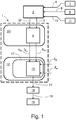
- the apparatus 1 is suitable for use with a highly autonomous drive system 2 or an advanced driver assistance system 2 of a road vehicle 3 having an electrical power assisted steering (EPAS) 40.
- the highly autonomous drive system 2 or advanced driver assistance system 2 of the road vehicle 3 having situation awareness through being arranged to receive internal state data 10 from one or more road vehicle 3 internal state measurement units 11 and at least one of ambient information 6 on the road vehicle 3 surroundings from one or more road vehicle 3 surrounding monitoring cameras 7 and map data 8 relating to the road vehicle 3 surroundings from a road vehicle 3 localization system 9, such as e.g. a GPS based navigational system.
- FIG. 1 illustrates the apparatus 1 schematically.
- a lateral controller 4 arranged in a domain 20 outside of a power steering control module (PSCM) 12, is arranged to receive, from the highly autonomous drive system 2 or advanced driver assistance system 2, information on a desired path 5.
- the lateral controller 4 is further arranged to output a wheel angle request ⁇ w,r (index r for request).
- the power steering control module 12 comprises a wheel angle controller 13.
- the wheel angle controller 13 is arranged to receive as inputs the wheel angle request ⁇ w,r from the lateral controller 4 as well as wheel angle ⁇ w and wheel angle rate ⁇ w data from one or more sensors (not shown) of the road vehicle 3 steering system.
- the wheel angle controller 13 is further arranged to output an overlay torque request 14 suitable for a motor controller 15 of a steering system 16 of the road vehicle 3.
- the overlay torque request 14 can be identified as a QM hazard which does not dictate any safety requirements, why it is subject to an overlay torque safety limiter 18 which provides a safety limited overlay torque request 19 that fulfil Automotive Safety Integrity Level D, which is the highest classification of initial hazard (injury risk) defined within ISO 26262 and to that standard's most stringent level of safety measures to apply for avoiding an unreasonable residual risk.
- Automotive Safety Integrity Level D which is the highest classification of initial hazard (injury risk) defined within ISO 26262 and to that standard's most stringent level of safety measures to apply for avoiding an unreasonable residual risk.
- the highly autonomous drive system 2 or advanced driver assistance system 2 is arranged to generate a penalty measure 32 indicative of how penalties should be handled in the lateral controller 4 based on the internal state data 10 and at least one of the ambient information 6 and the map data 8.
- the lateral controller 4 is further arranged to calculate gain parameters I ⁇ w , I ⁇ w , based on the penalty measure 32, and to output to the wheel angle controller 13 the calculated gain parameters I ⁇ w , I ⁇ w .
- the calculated gain parameters I ⁇ w , I ⁇ w are continuously sent to the wheel angle controller 13 of the power steering control module 12, which makes it possible to alter closed loop wheel angle dynamics as the road vehicle 3 enters new traffic situations and environments, as will be elaborated in the following.
- the wheel angle controller 13 is further arranged to receive and use the gain parameters I ⁇ w , I ⁇ w in control loops of the wheel angle controller 13.
- the gain parameters I ⁇ w , I ⁇ w are used in the control loops such that the bandwidth of the wheel angle controller 13 is increased if one or more of the ambient information 6, the map data 8 and the internal state data 10 indicate a need for increased control speed and accuracy for safely tracking the desired path 5, and reduced if one or more of the ambient information 6, the map data 8 and the internal state data 10 indicate that decreased control speed and accuracy can be allowed whilst still safely tracking the desired path 5.
- the above provides for using high bandwidth in the wheel angle controller 13 in order for the desired path 5 to be tracked with increased accuracy and responsiveness when a traffic situation so requires, such as when free-space for safe maneuvers around the road vehicle 3 is limited, e.g. if the road vehicle 3 is passing a large truck, driving in a narrow lane or if a forward vehicle is cutting in ahead of the road vehicle 3. It further provides for using reduced bandwidth in traffic situations allowing to provide for slightly less precise and responsive and therefore more smooth and comfortable control for tracking the desired path 5 in situations where there is more space for performing safe maneuvering, such as when driving on a wide lane or on a straight road with ample space for safe maneuvering.
- the ambient information 6 and map data 8 provides for situation awareness, which is normally not available in the power steering control module 12. Moreover, it is not possible to move wheel angle control loops of the wheel angle controller 13 outside the power steering control module 12 due to the communication delays that would result therefrom. The above solution is thus more or less insensitive to time delays between the lateral controller 4 and the power steering control module 12 since the lateral controller 4 will not require any information on the current state of the power steering control module 12.
- the lateral controller 4 is further arranged to calculate the gain parameters I ⁇ w , I ⁇ w to provide for increased control speed and accuracy in tracking of the desired path 5 if at least one of the ambient information 6, the map data 8 and the internal state data 10 indicate a reduced margin for safe road vehicle 3 travel along the desired path 5.
- the lateral controller 4 is further arranged to calculate the gain parameters I ⁇ w , I ⁇ w to provide for decreased control speed and accuracy in tracking of the desired path 5 if at least one of the ambient information 6, the map data 8 and the internal state data 10 indicate an increased margin for safe road vehicle 3 travel along the desired path 5.
- margin for safe road vehicle 3 travel along the desired path 5 is here meant to encompass physical margins for unobstructed road vehicle 3 travel, such as distances to surrounding infrastructure and vehicles, allowable velocities and acceleration with respect to surrounding traffic etc..
- a desired path 5 to be tracked with increased accuracy and responsiveness when a traffic situation so requires, such as when free-space for safe maneuvers is limited as well as for comfortable, calm and steady control when driving with ample space for safe maneuvering, such as on a wide lane or on a straight road.
- the wheel angle controller 13 is arranged to execute a wheel angle control loop and a wheel angle rate control loop and the lateral controller 4 is arranged to calculate a gain parameter I ⁇ w for the wheel angle control loop and a gain parameter I ⁇ w for the wheel angle rate control loop of the wheel angle controller 13.
- the wheel angle controller 13 is arranged to execute an outer wheel angle control loop and an inner wheel angle rate control loop and that the lateral controller 4 is arranged to calculate a gain parameter I ⁇ w,o for the outer wheel angle control loop (index o for outer) and a gain parameter I ⁇ w,i for the inner wheel angle rate control loop (index i for inner) of the wheel angle controller 13.
- the lateral controller 4 has a linear quadratic problem formulation with a quadratic penalty on wheel angle rate ⁇ w and wheel angle acceleration ⁇ w and the linear quadratic problem formulation is used to calculate the gain parameters I ⁇ w , I ⁇ w,o , I ⁇ w , I ⁇ w,i .
- This as it in the linear quadratic problem formulation is natural to consider the wheel angle rate ⁇ w as the control signal, which means that the linear quadratic problem will decide the gains used in the wheel angle ⁇ w control loop.
- this provides an efficient way to provide gain parameters I ⁇ w , I ⁇ w,o , I ⁇ w , I ⁇ w,i enabling recreation in the power steering control module 12 of a wheel angle rate request ⁇ w,r in an active safety domain master of the highly autonomous drive system 2 or advanced driver assistance system 2.
- the power steering control module 12 is arranged to recreate a wheel angle rate request ⁇ w,r for the wheel angle rate control loop of the wheel angle controller 13 from the gain parameter I ⁇ w , I ⁇ w,o for the wheel angle control loop and the gain parameter I ⁇ w , I ⁇ w,i for the wheel angle rate control loop, the wheel angle request ⁇ w,r , the wheel angle ⁇ w and the wheel angle rate data ⁇ w .
- This provides a simple and reliable way of ensuring improved control by the wheel angle controller 13.
- this is achieved through the power steering control module 12 being arranged to recreate the wheel angle rate request ⁇ w,r for the wheel angle rate control loop of the wheel angle controller 13 as the gain parameter for the wheel angle control loop I ⁇ w , I ⁇ w,o multiplied with the difference between the wheel angle request ⁇ w,r and the wheel angle ⁇ w reduced with the product of the gain parameter for the wheel angle rate control loop I ⁇ w , I ⁇ w,i and the wheel angle rate data ⁇ w .
- a steer torque manager 17 that comprises a wheel angle controller 13 arranged to receive and use the gain parameters I ⁇ w , I ⁇ w in control loops of the wheel angle controller 13, as described above.
- a steer torque manager commonly abbreviated as STM, is a component that is commonly located in an EPAS supplier node, herein referred to as Power Steering Control Module, commonly abbreviated as PSCM.
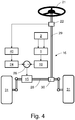
- FIG 3 is a schematic illustration of a road vehicle steering system comprising the apparatus of figure 1 arranged with an electrical power assisted steering system 40 thereof.
- the apparatus of figure 1 may be arranged with an electrical power assisted steering system 40 of a road vehicle 3.
- the steer torque manager 17, may further be arranged such that a steering wheel 21 torque applied by a driver of the road vehicle 3, is sensed by a steering wheel torque sensor 22 and used by an electrical power assisted steering (EPAS) assistance functionality 40 to provide an assistance torque request 23, for assisting a driver when during manual or semi-automated steering control of the road vehicle 3.
- EATS electrical power assisted steering
- Such an assistance torque request 23 is normally also identified as a QM hazard which does not dictate any safety requirements according to the Automotive Safety Integrity Level (ASIL) risk classification scheme defined by the ISO 26262 - Functional Safety for Road Vehicles standard, and is therefore normally also subject to an assistance torque safety limiter 24 which in turn provide a safety limited assistance torque request 25 which is then suitably brought to a summation point 26 to be added to the safety limited overlay torque request 19, and which summation point in turn provides a total torque request 27 to the motor controller 15 of the steering system of the road vehicle 3.
- ASIL Automotive Safety Integrity Level
- a road vehicle 3 as illustrated in figure 2 , which has an apparatus 1 for situation dependent wheel angle ⁇ w control by a highly autonomous drive system 2 or an advanced driver assistance system 2, as described above with reference to figure 1 .
- the apparatus 1 of figure 1 e.g. arranged with an electrical power assisted steering system 40 as illustrated in figure 3
- the apparatus 1 of figure 1 may be arranged in a steering system 16 of the road vehicle 3 that comprises a steering wheel 21, connected to a steering rack 28 via a torsion bar 29, to which a steering wheel torque sensor 22 is arranged, and a pinion gear 30.
- the power steering control module 27 comprises the apparatus 1, which is arranged to control the overlay torque motor 15 of the steering system 16 of the road vehicle 3 to provide an overlay torque to steerable wheels 31 of the vehicle 3 steering system 16.
- a method for situation dependent wheel angle ⁇ w control by a highly autonomous drive system 2 or an advanced driver assistance system 2 of a road vehicle 3 the highly autonomous drive system 2 or advanced driver assistance system 2 being arranged to receive internal state data 10 from one or more road vehicle 3 internal state measurement units 11 and at least one of ambient information 6 on the road vehicle 3 surroundings from one or more road vehicle 3 surrounding monitoring cameras 7 and map data 8 relating to the road vehicle 3 surroundings from a road vehicle 3 localization system 9.
- the method is adapted for a road vehicle 3 comprising a lateral controller 4 arranged to receive from the highly autonomous drive system 2 or advanced driver assistance system 2 information on a desired path 5, and to output a wheel angle request ⁇ w,r .
- the method is further adapted for a road vehicle 3 having power steering control module 12 that comprises a wheel angle controller 13, where the wheel angle controller 13 is arranged to receive as inputs the wheel angle request ⁇ w,r from the lateral controller 4 as well as wheel angle ⁇ w and wheel angle rate ⁇ w data, and where the wheel angle controller 13 further is arranged to output an overlay torque request 14 suitable for a motor controller 15 of a steering system 16 of the road vehicle 3.
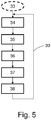
- the method starts out at 33, next at 34 is generated by the highly autonomous drive system 2 or advanced driver assistance system 2 a penalty measure 32 indicative of how penalties should be handled in the lateral controller 4 based on the internal state data 10 and at least one of the ambient information 6 and the map data 8.
- a penalty measure 32 indicative of how penalties should be handled in the lateral controller 4 based on the internal state data 10 and at least one of the ambient information 6 and the map data 8.
- gain parameters I ⁇ w , I ⁇ w are output to the wheel angle controller 13 at 36.
- the wheel angle controller 13 receives the calculated gain parameters I ⁇ w , I ⁇ w at 37, and uses them at 38 in control loops of the wheel angle controller 13, to increase the bandwidth of the wheel angle controller 13 if one or more of the ambient information 6, the map data 8 and the internal state data 10 indicate a need for increased control speed and accuracy for safely tracking the desired path 5, and to reduce the bandwidth of the wheel angle controller 13 if one or more of the ambient information 6, the map data 8 and the internal state data 10 indicate that decreased control speed and accuracy can be allowed whilst still safely tracking the desired path 5, whereupon the method at 39 loops back to start.
- a method as above provides for using high bandwidth in a wheel angle controller 13 in order for a desired path 5 to be tracked with increased control speed and accuracy when a traffic situation so requires, such as when free-space for safe maneuvers is limited, and reduced bandwidth in traffic situations allowing smooth and comfortable control for tracking the desired path 5 in traffic situations where there is more space for performing safe maneuvering.
Landscapes
- Engineering & Computer Science (AREA)
- Transportation (AREA)
- Mechanical Engineering (AREA)
- Chemical & Material Sciences (AREA)
- Combustion & Propulsion (AREA)
- Physics & Mathematics (AREA)
- General Physics & Mathematics (AREA)
- Radar, Positioning & Navigation (AREA)
- Automation & Control Theory (AREA)
- Remote Sensing (AREA)
- Aviation & Aerospace Engineering (AREA)
- Mathematical Physics (AREA)
- Computer Vision & Pattern Recognition (AREA)
- Multimedia (AREA)
- Electromagnetism (AREA)
- Steering Control In Accordance With Driving Conditions (AREA)
Claims (10)
- Appareil (1) de commande d'angle des roues (δw ) fonction de la situation par un système de conduite hautement autonome (2) ou un système avancé d'aide à la conduite (2) d'un véhicule routier (3), le système de conduite hautement autonome (2) ou le système avancé d'aide à la conduite (2) étant conçu pour recevoir des données d'état interne (10) en provenance d'une ou de plusieurs unités de mesure d'état interne (11) du véhicule routier (3) ainsi que des informations ambiantes (6) sur le milieu environnant du véhicule routier (3) en provenance d'une ou de plusieurs caméras (7) de surveillance du milieu environnant du véhicule routier (3) et/ou des données cartographiques (8) relatives au milieu environnant du véhicule routier (3) en provenance d'un système de localisation (9) du véhicule routier (3), l'appareil (1) comprenant : un contrôleur latéral (4) conçu pour recevoir, depuis le système de conduite hautement autonome (2) ou le système avancé d'aide à la conduite (2), des informations sur une trajectoire souhaitée (5), et pour fournir en sortie une demande d'angle des roues (δw,r ) ; un module de commande de direction assistée (12) comprenant un contrôleur d'angle des roues (13) conçu pour recevoir, en entrées, la demande d'angle des roues (δw,r ) en provenance du contrôleur latéral (4) ainsi que des données d'angle des roues (δw ) et de vitesse d'angle des roues (δ̇w ), et pour fournir en sortie une demande de couple de superposition (14) applicable à un contrôleur de moteur (15) d'un système de direction (16) du véhicule routier (3), le système de conduite hautement autonome (2) ou le système avancé d'aide à la conduite (2) étant conçu pour générer une mesure de pénalités (32) indiquant la façon dont il convient de traiter des pénalités dans le contrôleur latéral (4) sur la base des données d'état interne (10) ainsi que des informations ambiantes (6) et/ou des données cartographiques (8), et
que le contrôleur latéral (4) est conçu en outre pour calculer des paramètres de gain (Iδw ,Iδ̇w ) sur la base de la mesure de pénalités (32) et pour fournir en sortie au contrôleur d'angle des roues (13) les paramètres de gain calculés (Iδw ,Iδ̇ w ) ; et caractérisé par w w le fait que le contrôleur d'angle des roues (13) est conçu en outre pour recevoir et utiliser les paramètres de gain (Iδw ,Iδ̇w ) dans des boucles de commande du w w contrôleur d'angle des roues (13), de façon à accroître la largeur de bande du contrôleur d'angle des roues (13) si les informations ambiantes (6) et/ou les données cartographiques (8) et/ou les données d'état interne (10) indiquent un besoin d'accroître la vitesse et la précision de commande pour assurer un suivi en toute sécurité de la trajectoire souhaitée (5) et à les réduire si les informations ambiantes (6) et/ou les données cartographiques (8) et/ou les données d'état interne (10) indiquent qu'une diminution de la vitesse et de la précision de commande peut être admise en assurant toujours un suivi en toute sécurité de la trajectoire souhaitée (5), le contrôleur d'angle des roues (13) étant conçu pour exécuter une boucle de commande d'angle des roues et une boucle de commande de vitesse d'angle des roues, et que le contrôleur latéral (4) est conçu pour calculer un paramètre de gain (Iδw ) pour la boucle de commande d'angle des roues et un paramètre de gain (Iδ̇w ) pour la boucle de commande de vitesse d'angle des roues du contrôleur d'angle des roues (13). - Appareil (1) selon la revendication 1, caractérisé par le fait que le contrôleur latéral (4) est conçu en outre pour calculer les paramètres de gain (Iδ
w ,Iδ̇w ) afin d'accroître la vitesse et la précision de commande dans le suivi de la trajectoire souhaitée (5) si les informations ambiantes (6) et/ou les données cartographiques (8) et/ou les données d'état interne (10) indiquent une marge réduite pour un parcours en toute sécurité du véhicule routier (3) le long de la trajectoire souhaitée (5). - Appareil (1) selon la revendication 1, caractérisé par le fait que le contrôleur latéral (4) est conçu en outre pour calculer les paramètres de gain (Iδ
w ,Iδ̇w ) afin de diminuer la vitesse et la précision de commande dans le suivi de la trajectoire souhaitée (5) si les informations ambiantes (6) et/ou les données cartographiques (8) et/ou les données d'état interne (10) indiquent une marge accrue pour un parcours en toute sécurité du véhicule routier (3) le long de la trajectoire souhaitée (5). - Appareil (1) selon l'une quelconque des revendications 1 à 3, caractérisé par le fait que le contrôleur d'angle des roues (13) est conçu pour exécuter une boucle externe de commande d'angle des roues et une boucle interne de commande de vitesse d'angle des roues et que le contrôleur latéral (4) est conçu pour calculer un paramètre de gain (Iδ
w,o ) pour la boucle externe de commande d'angle des roues et un paramètre de gain (Iδ̇w,i ) pour la boucle interne de commande de vitesse d'angle des roues du contrôleur d'angle des roues (13). - Appareil (1) selon l'une quelconque des revendications 1 à 4, caractérisé par le fait que le contrôleur latéral (4) dispose d'une formulation de problème quadratique linéaire avec une pénalité quadratique sur la vitesse d'angle des roues (δ̇w ) et l'accélération d'angle des roues (δ̈w ), et la formulation de problème quadratique linéaire sert à calculer les paramètres de gain (Iδ
w ,Iδw,o Iδ̇w ,Iδ̇w,i ). - Appareil (1) selon l'une quelconque des revendications 1 à 5, caractérisé par le fait que le module de commande de direction assistée (12) est conçu pour recréer une demande de vitesse d'angle des roues (δ̇w,r ) pour la boucle de commande de vitesse d'angle des roues du contrôleur d'angle des roues (13) à partir du paramètre de gain pour la boucle de commande d'angle des roues (Iδ
w ,Iδw,o ) et du paramètre de gain pour la boucle de commande de vitesse d'angle des roues (Iδ̇w ,Iδ̇w,i ), de la demande d'angle des roues (δw,r ), de l'angle des roues (δw ) et des données de vitesse d'angle des roues (δ̇w ). - Appareil (1) selon la revendication 6, caractérisé par le fait que le module de commande de direction assistée (12) est conçu pour recréer la demande de vitesse d'angle des roues (δ̇w,r ) pour la boucle de commande de vitesse d'angle des roues du contrôleur d'angle des roues (13) sous forme du paramètre de gain pour la boucle de commande d'angle des roues (Iδ
w ,Iδw,o ) multiplié par la différence entre la demande d'angle des roues (δw,r ) et l'angle des roues (δw ) réduite par le produit du paramètre de gain pour la boucle de commande de vitesse d'angle des roues (Iδ̇w ,Iδ̇w,i ) et des données de vitesse d'angle des roues (δ̇w ). - Gestionnaire de couple de braquage (17), caractérisé par le fait qu'il comprend un contrôleur d'angle des roues (13) conçu pour recevoir et utiliser des paramètres de gain (Iδ
w ,Iδ̇w ) selon l'une quelconque des revendications 1 à 7 dans des boucles de commande du contrôleur d'angle des roues (13). - Véhicule routier (3), caractérisé par le fait qu'il comprend un appareil selon l'une quelconque des revendications 1 à 7.
- Procédé de commande d'angle des roues (δw ) fonction de la situation par un système de conduite hautement autonome (2) ou un système avancé d'aide à la conduite (2) d'un véhicule routier (3), le système de conduite hautement autonome (2) ou le système avancé d'aide à la conduite (2) étant conçu pour recevoir des données d'état interne (10) en provenance d'une ou de plusieurs unités de mesure d'état interne (11) du véhicule routier (3) ainsi que des informations ambiantes (6) sur le milieu environnant du véhicule routier (3) en provenance d'une ou de plusieurs caméras (7) de surveillance du milieu environnant du véhicule routier (3) et/ou des données cartographiques (8) relatives au milieu environnant du véhicule routier (3) en provenance d'un système de localisation (9) du véhicule routier (3), le véhicule routier (3) comprenant : un contrôleur latéral (4) conçu pour recevoir, depuis le système de conduite hautement autonome (2) ou le système avancé d'aide à la conduite (2), des informations sur une trajectoire souhaitée (5), et pour fournir en sortie une demande d'angle des roues (δw,r ) ; un module de commande de direction assistée (12) comprenant un contrôleur d'angle des roues (13) conçu pour recevoir, en entrées, la demande d'angle des roues (δw,r ) en provenance du contrôleur latéral (4) ainsi que des données d'angle des roues (δw ) et de vitesse d'angle des roues (δ̇w ) , et pour fournir en sortie une demande de couple de superposition (14) applicable à un contrôleur de moteur (15) d'un système de direction (16) du véhicule routier (3), le procédé comprenant :la génération, par le système de conduite hautement autonome (2) ou le système avancé d'aide à la conduite (2), d'une mesure de pénalités (32) indiquant la façon dont il convient de traiter des pénalités dans le contrôleur latéral (4) sur la base des données d'état interne (10) ainsi que des informations ambiantes (6) et/ou des données cartographiques (8), etle calcul, dans le contrôleur latéral (4), de paramètres de gain (Iδ
w ,Iδ̇w ) sur la base de la mesure de pénalités (32) et la fourniture en sortie au contrôleur d'angle des roues (13) des paramètres de gain calculés (Iδw ,Iδ̇w ) ;le procédé étant caractérisé par le fait qu'il comprend en outre :la réception, au contrôleur d'angle des roues (13), des paramètres de gain (Iδw ,Iδ̇w ) et leur utilisation dans des boucles de commande du contrôleur d'angle des roues (13), de façon à accroître la largeur de bande du contrôleur d'angle des roues (13) si les informations ambiantes (6) et/ou les données cartographiques (8) et/ou les données d'état interne (10) indiquent un besoin d'accroître la vitesse et la précision de commande pour assurer un suivi en toute sécurité de la trajectoire souhaitée (5) et à les réduire si les informations ambiantes (6) et/ou les données cartographiques (8) et/ou les données d'état interne (10) indiquent qu'une diminution de la vitesse et de la précision de commande peut être admise en assurant toujours un suivi en toute sécurité de la trajectoire souhaitée (5),l'exécution, au niveau du contrôleur d'angle des roues (13), d'une boucle de commande d'angle des roues et d'une boucle de commande de vitesse d'angle des roues ; etle calcul, au niveau du contrôleur latéral (4), d'un paramètre de gain (Iδw ) pour la boucle de commande d'angle des roues et d'un paramètre de gain (Iδ̇w ) pour la boucle de commande de vitesse d'angle des roues du contrôleur d'angle des roues (13).
Priority Applications (3)
| Application Number | Priority Date | Filing Date | Title |
|---|---|---|---|
| EP17161795.4A EP3378733B1 (fr) | 2017-03-20 | 2017-03-20 | Appareil et procédé de commande d'angle de roue en fonction de la situation (had ou adas) |
| CN201810199002.6A CN108622183B (zh) | 2017-03-20 | 2018-03-12 | 用于状况相关的had或adas车轮转角控制器的设备和方法 |
| US15/920,019 US10640145B2 (en) | 2017-03-20 | 2018-03-13 | Apparatus and method for situation dependent had or ADAS wheel angle control |
Applications Claiming Priority (1)
| Application Number | Priority Date | Filing Date | Title |
|---|---|---|---|
| EP17161795.4A EP3378733B1 (fr) | 2017-03-20 | 2017-03-20 | Appareil et procédé de commande d'angle de roue en fonction de la situation (had ou adas) |
Publications (2)
| Publication Number | Publication Date |
|---|---|
| EP3378733A1 EP3378733A1 (fr) | 2018-09-26 |
| EP3378733B1 true EP3378733B1 (fr) | 2020-01-15 |
Family
ID=58387731
Family Applications (1)
| Application Number | Title | Priority Date | Filing Date |
|---|---|---|---|
| EP17161795.4A Active EP3378733B1 (fr) | 2017-03-20 | 2017-03-20 | Appareil et procédé de commande d'angle de roue en fonction de la situation (had ou adas) |
Country Status (3)
| Country | Link |
|---|---|
| US (1) | US10640145B2 (fr) |
| EP (1) | EP3378733B1 (fr) |
| CN (1) | CN108622183B (fr) |
Families Citing this family (10)
| Publication number | Priority date | Publication date | Assignee | Title |
|---|---|---|---|---|
| EP3360757B1 (fr) | 2017-02-10 | 2019-10-02 | Volvo Car Corporation | Gestionnaire de couple de braquage avancé destiné à un système d'aide au conducteur d'un véhicule routier |
| EP3375696B1 (fr) | 2017-03-17 | 2019-11-20 | Volvo Car Corporation | Gestionnaire de couple de braquage destinés à un système d'aide au conducteur d'un véhicule routier |
| US10282998B2 (en) * | 2017-03-17 | 2019-05-07 | Denso International America, Inc. | Vehicle system and vehicle controller for controlling vehicle |
| EP3378731B1 (fr) | 2017-03-20 | 2020-01-15 | Volvo Car Corporation | Appareil et procédé de commande d'angle de roue fonction de l'activité du conducteur (adas) |
| DE102017207391B4 (de) * | 2017-05-03 | 2019-02-28 | Ford Global Technologies, Llc | Verfahren zum Erzeugen eines an eine momentane Fahrsituation eines Fahrzeugs angepassten resultierenden Hilfslenkmoments unter Verwendung eines aktiven Lenkunterstützungssystems sowie Lenkunterstützungssystem |
| CN110884563A (zh) * | 2019-12-12 | 2020-03-17 | 上海衡鲁汽车科技有限公司 | 一种电动助力高级驾驶辅助系统 |
| EP4252222A1 (fr) * | 2020-11-26 | 2023-10-04 | BAE SYSTEMS plc | Procédé et appareil de roulage autonome |
| US11999417B2 (en) * | 2021-11-29 | 2024-06-04 | Volvo Car Corporation | Steering angle control using haptic controller |
| CN117037473B (zh) * | 2023-07-27 | 2026-03-27 | 南斗六星(武汉)技术有限公司 | 一种基于车道的车辆车头展示方向纠正方法 |
| CN119590508A (zh) * | 2024-12-31 | 2025-03-11 | 广州市柏琳汽车零件制造有限公司 | 应用于新能源汽车的转向驾驶辅助系统 |
Family Cites Families (62)
| Publication number | Priority date | Publication date | Assignee | Title |
|---|---|---|---|---|
| JP2671626B2 (ja) * | 1991-04-08 | 1997-10-29 | 日産自動車株式会社 | 走行情報提供装置 |
| GB9317983D0 (en) | 1993-08-28 | 1993-10-13 | Lucas Ind Plc | A driver assistance system for a vehicle |
| US6053270A (en) | 1995-11-02 | 2000-04-25 | Honda Giken Kogyo Kabushiki Kaisha | Steering angle correcting system in vehicle |
| JP3647538B2 (ja) * | 1996-02-12 | 2005-05-11 | 本田技研工業株式会社 | 車両操舵装置 |
| JP3314866B2 (ja) | 1997-09-13 | 2002-08-19 | 本田技研工業株式会社 | 車両用操舵装置 |
| JP2001256598A (ja) * | 2000-03-08 | 2001-09-21 | Honda Motor Co Ltd | 危険箇所報知システム |
| US8280533B2 (en) * | 2000-06-20 | 2012-10-02 | Fisher-Rosemount Systems, Inc. | Continuously scheduled model parameter based adaptive controller |
| KR20020094545A (ko) | 2001-06-12 | 2002-12-18 | 현대자동차주식회사 | 자동차의 차선 이탈 방지시스템 및 그 제어방법 |
| JP3866532B2 (ja) * | 2001-06-13 | 2007-01-10 | 富士通株式会社 | 移動体安全運行支援装置およびコンピュータプログラム |
| JP3585874B2 (ja) | 2001-09-04 | 2004-11-04 | 本田技研工業株式会社 | 車両の走行制御装置 |
| US6879896B2 (en) | 2002-04-11 | 2005-04-12 | Delphi Technologies, Inc. | System and method for using vehicle operator intent to adjust vehicle control system response |
| US7499949B2 (en) * | 2002-08-07 | 2009-03-03 | Navteq North America, Llc | Method and system for obtaining recurring delay data using navigation systems |
| US7510038B2 (en) | 2003-06-11 | 2009-03-31 | Delphi Technologies, Inc. | Steering system with lane keeping integration |
| WO2005003885A2 (fr) * | 2003-07-07 | 2005-01-13 | Sensomatix Ltd. | Systeme d'information routiere |
| JP4161938B2 (ja) * | 2004-06-01 | 2008-10-08 | トヨタ自動車株式会社 | 走行制御装置 |
| US7664584B2 (en) * | 2005-03-01 | 2010-02-16 | Nissan Motor Co., Ltd. | Steering control system |
| WO2007048003A2 (fr) | 2005-10-21 | 2007-04-26 | Deere & Company | Module de commande robotique polyvalent |
| JP4449960B2 (ja) | 2006-08-22 | 2010-04-14 | トヨタ自動車株式会社 | 操舵支援装置 |
| JP4419997B2 (ja) * | 2006-08-28 | 2010-02-24 | トヨタ自動車株式会社 | 電動パワーステアリング装置 |
| DE602008004435D1 (de) | 2008-04-02 | 2011-02-24 | Gm Global Tech Operations Inc | Adaptive Lenksteuerung für ein Kraftfahrzeug |
| US8392064B2 (en) | 2008-05-27 | 2013-03-05 | The Board Of Trustees Of The Leland Stanford Junior University | Systems, methods and devices for adaptive steering control of automotive vehicles |
| EP2159777A3 (fr) * | 2008-05-30 | 2016-05-04 | HERE Global B.V. | Exploration de données pour identifier les emplacements des conditions potentiellement dangereuses pour le fonctionnement de véhicule et utilisation associée |
| US8170751B2 (en) | 2008-12-17 | 2012-05-01 | GM Global Technology Operations LLC | Detection of driver intervention during a torque overlay operation in an electric power steering system |
| DE102010028384A1 (de) * | 2009-05-07 | 2010-11-11 | Continental Teves Ag & Co. Ohg | Verfahren und Vorrichtung zur Regelung bzw. Steuerung der Fahrstabilität eines Fahrzeugs |
| EP2448806B1 (fr) | 2009-06-29 | 2015-04-22 | Volvo Lastvagnar AB | Procédé et système pour aider un conducteur d'un véhicule lors d'une opération |
| JP5540092B2 (ja) | 2009-06-29 | 2014-07-02 | ボルボ ラストバグナー アーベー | 車両の軌道を変更するための方法及びシステム |
| US8270605B2 (en) * | 2009-09-01 | 2012-09-18 | Sony Corporation | Location authentication |
| EP2546122B1 (fr) * | 2010-03-12 | 2015-04-22 | Toyota Jidosha Kabushiki Kaisha | Dispositif de support de direction |
| JP5429062B2 (ja) * | 2010-06-11 | 2014-02-26 | トヨタ自動車株式会社 | 車両の走行制御装置 |
| US8977419B2 (en) * | 2010-12-23 | 2015-03-10 | GM Global Technology Operations LLC | Driving-based lane offset control for lane centering |
| DE102012001666A1 (de) | 2012-01-28 | 2013-08-01 | Audi Ag | Verfahren zum Lenken eines Fahrzeugs mittels eines Lenkassistenzsystems |
| DE102013213216A1 (de) * | 2013-07-05 | 2015-01-08 | Robert Bosch Gmbh | Verfahren und Vorrichtung zum Unterstützen eines Fahrers eines Fahrzeugs in einer Engstelle |
| EP3057848B1 (fr) * | 2013-10-16 | 2018-04-11 | Sentient AB | Procédé de commande de comportement de véhicule |
| JP5988308B2 (ja) * | 2013-12-27 | 2016-09-07 | 富士重工業株式会社 | 車両のレーンキープ制御装置 |
| JP6378887B2 (ja) | 2014-02-04 | 2018-08-22 | Kyb株式会社 | 電動パワーステアリング装置 |
| JP2015231825A (ja) * | 2014-05-13 | 2015-12-24 | トヨタ自動車株式会社 | 車両の走行制御装置 |
| EP2949548B1 (fr) * | 2014-05-27 | 2018-07-11 | Volvo Car Corporation | Système et méthode de suppression de suivi de voie |
| FR3022515B1 (fr) * | 2014-06-24 | 2016-07-29 | Jtekt Europe Sas | Assistance de direction mixte comprenant une boucle d'asservissement en couple pilotee en consigne par un controleur de position destine a l'asservissement en trajectoire |
| JP5880801B1 (ja) * | 2014-07-31 | 2016-03-09 | 日本精工株式会社 | 電動パワーステアリング装置 |
| FR3026708B1 (fr) * | 2014-10-07 | 2016-11-18 | Jtekt Europe Sas | Securisation d'une fonction d'aide a la conduite au sein d'une direction assistee |
| CN107531275B (zh) * | 2014-11-07 | 2019-02-19 | 日本精工株式会社 | 电动助力转向装置 |
| JP6237656B2 (ja) | 2015-01-19 | 2017-11-29 | トヨタ自動車株式会社 | 車両システム |
| JP5990606B2 (ja) * | 2015-02-10 | 2016-09-14 | 本田技研工業株式会社 | 操舵装置及び操舵支援方法 |
| JP6612840B2 (ja) * | 2015-02-19 | 2019-11-27 | 本田技研工業株式会社 | 車両 |
| JP6087969B2 (ja) * | 2015-03-23 | 2017-03-01 | 富士重工業株式会社 | 車両の走行制御装置 |
| US9499202B2 (en) | 2015-04-15 | 2016-11-22 | Delphi Technologies, Inc. | Steering system and method for autonomous vehicles |
| JP2017001597A (ja) * | 2015-06-15 | 2017-01-05 | トヨタ自動車株式会社 | 自動運転装置 |
| EP3109119B1 (fr) * | 2015-06-23 | 2022-08-10 | Volvo Car Corporation | Procédé et agencement permettant des tâches secondaires pendant une conduite semi-automatique |
| JP6355167B2 (ja) | 2015-09-28 | 2018-07-11 | トヨタ自動車株式会社 | 車両の運転支援制御装置 |
| CN105711588B (zh) * | 2016-01-20 | 2018-05-11 | 奇瑞汽车股份有限公司 | 一种车道保持辅助系统和车道保持辅助方法 |
| JP6327719B2 (ja) * | 2016-02-04 | 2018-05-23 | 株式会社Subaru | 車両の走行制御装置 |
| US9586619B1 (en) * | 2016-02-12 | 2017-03-07 | Denso Corporation | Motor controller |
| US9731755B1 (en) * | 2016-02-16 | 2017-08-15 | GM Global Technology Operations LLC | Preview lateral control for automated driving |
| US9796421B1 (en) * | 2016-04-07 | 2017-10-24 | GM Global Technology Operations LLC | Autonomous vehicle lateral control for path tracking and stability |
| US10144453B2 (en) * | 2016-04-13 | 2018-12-04 | Cnh Industrial America Llc | System and method for controlling a vehicle |
| US10155534B2 (en) | 2016-06-14 | 2018-12-18 | Steering Solutions Ip Holding Corporation | Driver intent estimation without using torque sensor signal |
| CN106114507B (zh) * | 2016-06-21 | 2018-04-03 | 百度在线网络技术(北京)有限公司 | 用于智能车辆的局部轨迹规划方法和装置 |
| JP6647400B2 (ja) | 2016-07-12 | 2020-02-14 | 本田技研工業株式会社 | 運転支援装置 |
| US10545464B2 (en) * | 2016-12-01 | 2020-01-28 | The Boeing Company | Control system having variable gain feed forward (VGFF) control |
| EP3360757B1 (fr) | 2017-02-10 | 2019-10-02 | Volvo Car Corporation | Gestionnaire de couple de braquage avancé destiné à un système d'aide au conducteur d'un véhicule routier |
| EP3375696B1 (fr) | 2017-03-17 | 2019-11-20 | Volvo Car Corporation | Gestionnaire de couple de braquage destinés à un système d'aide au conducteur d'un véhicule routier |
| EP3378731B1 (fr) * | 2017-03-20 | 2020-01-15 | Volvo Car Corporation | Appareil et procédé de commande d'angle de roue fonction de l'activité du conducteur (adas) |
-
2017
- 2017-03-20 EP EP17161795.4A patent/EP3378733B1/fr active Active
-
2018
- 2018-03-12 CN CN201810199002.6A patent/CN108622183B/zh active Active
- 2018-03-13 US US15/920,019 patent/US10640145B2/en active Active
Non-Patent Citations (1)
| Title |
|---|
| None * |
Also Published As
| Publication number | Publication date |
|---|---|
| CN108622183B (zh) | 2020-08-14 |
| EP3378733A1 (fr) | 2018-09-26 |
| US10640145B2 (en) | 2020-05-05 |
| US20180265123A1 (en) | 2018-09-20 |
| CN108622183A (zh) | 2018-10-09 |
Similar Documents
| Publication | Publication Date | Title |
|---|---|---|
| EP3378733B1 (fr) | Appareil et procédé de commande d'angle de roue en fonction de la situation (had ou adas) | |
| JP6341137B2 (ja) | 車両の運転支援制御装置 | |
| US11059462B2 (en) | Method and device for controlling a movement of a vehicle, and vehicle movement control system | |
| US9278713B2 (en) | Collision avoidance control integrated with EPS controller | |
| JP6573643B2 (ja) | 車両の走行制御装置 | |
| EP2219925B1 (fr) | Assistance au guidage routier par assistance du couple au niveau du volant de direction | |
| US10179602B2 (en) | Driver assistance system for vehicle | |
| JP6269557B2 (ja) | 車両の運転支援制御装置 | |
| CN103183028B (zh) | 用于机动车辆的车道保持方法 | |
| CN108238099B (zh) | 车辆行驶控制装置及自主驾驶控制方法 | |
| EP3375696B1 (fr) | Gestionnaire de couple de braquage destinés à un système d'aide au conducteur d'un véhicule routier | |
| EP3266680B1 (fr) | Procédé et système permettant de sécuriser la limitation d'une intervention de superposition de couple dans un système de direction assistée d'un véhicule routier | |
| EP3378731B1 (fr) | Appareil et procédé de commande d'angle de roue fonction de l'activité du conducteur (adas) | |
| RU2672322C1 (ru) | Устройство управления движением транспортного средства и способ управления автономным движением | |
| CN104870293A (zh) | 驾驶辅助装置以及驾驶辅助方法 | |
| US10858001B2 (en) | System and method for controlling a vehicle steering system | |
| US20160009318A1 (en) | Collision avoidance assistance device and collision avoidance assistance method | |
| US20160031321A1 (en) | Predicted arrival point presentation device and computer readable medium | |
| GB2583898A (en) | Control system for driver monitoring and steering control | |
| CN109476342B (zh) | 检测地面上道路标记校正机动车辆行进方向的方法 | |
| JP2019112000A (ja) | 操舵アシスト装置 | |
| JP2018197078A (ja) | 操舵支援装置、操舵支援方法及びプログラム | |
| JP2024051387A (ja) | 車両用制御装置 |
Legal Events
| Date | Code | Title | Description |
|---|---|---|---|
| PUAI | Public reference made under article 153(3) epc to a published international application that has entered the european phase |
Free format text: ORIGINAL CODE: 0009012 |
|
| STAA | Information on the status of an ep patent application or granted ep patent |
Free format text: STATUS: THE APPLICATION HAS BEEN PUBLISHED |
|
| AK | Designated contracting states |
Kind code of ref document: A1 Designated state(s): AL AT BE BG CH CY CZ DE DK EE ES FI FR GB GR HR HU IE IS IT LI LT LU LV MC MK MT NL NO PL PT RO RS SE SI SK SM TR |
|
| AX | Request for extension of the european patent |
Extension state: BA ME |
|
| STAA | Information on the status of an ep patent application or granted ep patent |
Free format text: STATUS: REQUEST FOR EXAMINATION WAS MADE |
|
| 17P | Request for examination filed |
Effective date: 20190326 |
|
| RBV | Designated contracting states (corrected) |
Designated state(s): AL AT BE BG CH CY CZ DE DK EE ES FI FR GB GR HR HU IE IS IT LI LT LU LV MC MK MT NL NO PL PT RO RS SE SI SK SM TR |
|
| GRAP | Despatch of communication of intention to grant a patent |
Free format text: ORIGINAL CODE: EPIDOSNIGR1 |
|
| STAA | Information on the status of an ep patent application or granted ep patent |
Free format text: STATUS: GRANT OF PATENT IS INTENDED |
|
| RIC1 | Information provided on ipc code assigned before grant |
Ipc: G05D 1/02 20060101ALI20190709BHEP Ipc: B62D 6/00 20060101ALI20190709BHEP Ipc: B62D 5/04 20060101AFI20190709BHEP Ipc: G01C 21/26 20060101ALI20190709BHEP Ipc: B62D 15/02 20060101ALI20190709BHEP Ipc: G08G 1/16 20060101ALI20190709BHEP Ipc: G01G 21/26 20060101ALI20190709BHEP |
|
| INTG | Intention to grant announced |
Effective date: 20190812 |
|
| GRAS | Grant fee paid |
Free format text: ORIGINAL CODE: EPIDOSNIGR3 |
|
| GRAA | (expected) grant |
Free format text: ORIGINAL CODE: 0009210 |
|
| STAA | Information on the status of an ep patent application or granted ep patent |
Free format text: STATUS: THE PATENT HAS BEEN GRANTED |
|
| AK | Designated contracting states |
Kind code of ref document: B1 Designated state(s): AL AT BE BG CH CY CZ DE DK EE ES FI FR GB GR HR HU IE IS IT LI LT LU LV MC MK MT NL NO PL PT RO RS SE SI SK SM TR |
|
| REG | Reference to a national code |
Ref country code: CH Ref legal event code: EP Ref country code: GB Ref legal event code: FG4D |
|
| REG | Reference to a national code |
Ref country code: IE Ref legal event code: FG4D |
|
| REG | Reference to a national code |
Ref country code: DE Ref legal event code: R096 Ref document number: 602017010806 Country of ref document: DE |
|
| REG | Reference to a national code |
Ref country code: AT Ref legal event code: REF Ref document number: 1224927 Country of ref document: AT Kind code of ref document: T Effective date: 20200215 |
|
| REG | Reference to a national code |
Ref country code: NL Ref legal event code: MP Effective date: 20200115 |
|
| REG | Reference to a national code |
Ref country code: LT Ref legal event code: MG4D |
|
| PG25 | Lapsed in a contracting state [announced via postgrant information from national office to epo] |
Ref country code: NO Free format text: LAPSE BECAUSE OF FAILURE TO SUBMIT A TRANSLATION OF THE DESCRIPTION OR TO PAY THE FEE WITHIN THE PRESCRIBED TIME-LIMIT Effective date: 20200415 Ref country code: FI Free format text: LAPSE BECAUSE OF FAILURE TO SUBMIT A TRANSLATION OF THE DESCRIPTION OR TO PAY THE FEE WITHIN THE PRESCRIBED TIME-LIMIT Effective date: 20200115 Ref country code: RS Free format text: LAPSE BECAUSE OF FAILURE TO SUBMIT A TRANSLATION OF THE DESCRIPTION OR TO PAY THE FEE WITHIN THE PRESCRIBED TIME-LIMIT Effective date: 20200115 Ref country code: NL Free format text: LAPSE BECAUSE OF FAILURE TO SUBMIT A TRANSLATION OF THE DESCRIPTION OR TO PAY THE FEE WITHIN THE PRESCRIBED TIME-LIMIT Effective date: 20200115 Ref country code: PT Free format text: LAPSE BECAUSE OF FAILURE TO SUBMIT A TRANSLATION OF THE DESCRIPTION OR TO PAY THE FEE WITHIN THE PRESCRIBED TIME-LIMIT Effective date: 20200607 |
|
| PG25 | Lapsed in a contracting state [announced via postgrant information from national office to epo] |
Ref country code: BG Free format text: LAPSE BECAUSE OF FAILURE TO SUBMIT A TRANSLATION OF THE DESCRIPTION OR TO PAY THE FEE WITHIN THE PRESCRIBED TIME-LIMIT Effective date: 20200415 Ref country code: GR Free format text: LAPSE BECAUSE OF FAILURE TO SUBMIT A TRANSLATION OF THE DESCRIPTION OR TO PAY THE FEE WITHIN THE PRESCRIBED TIME-LIMIT Effective date: 20200416 Ref country code: LV Free format text: LAPSE BECAUSE OF FAILURE TO SUBMIT A TRANSLATION OF THE DESCRIPTION OR TO PAY THE FEE WITHIN THE PRESCRIBED TIME-LIMIT Effective date: 20200115 Ref country code: IS Free format text: LAPSE BECAUSE OF FAILURE TO SUBMIT A TRANSLATION OF THE DESCRIPTION OR TO PAY THE FEE WITHIN THE PRESCRIBED TIME-LIMIT Effective date: 20200515 Ref country code: SE Free format text: LAPSE BECAUSE OF FAILURE TO SUBMIT A TRANSLATION OF THE DESCRIPTION OR TO PAY THE FEE WITHIN THE PRESCRIBED TIME-LIMIT Effective date: 20200115 Ref country code: HR Free format text: LAPSE BECAUSE OF FAILURE TO SUBMIT A TRANSLATION OF THE DESCRIPTION OR TO PAY THE FEE WITHIN THE PRESCRIBED TIME-LIMIT Effective date: 20200115 |
|
| REG | Reference to a national code |
Ref country code: DE Ref legal event code: R097 Ref document number: 602017010806 Country of ref document: DE |
|
| PG25 | Lapsed in a contracting state [announced via postgrant information from national office to epo] |
Ref country code: DK Free format text: LAPSE BECAUSE OF FAILURE TO SUBMIT A TRANSLATION OF THE DESCRIPTION OR TO PAY THE FEE WITHIN THE PRESCRIBED TIME-LIMIT Effective date: 20200115 Ref country code: LT Free format text: LAPSE BECAUSE OF FAILURE TO SUBMIT A TRANSLATION OF THE DESCRIPTION OR TO PAY THE FEE WITHIN THE PRESCRIBED TIME-LIMIT Effective date: 20200115 Ref country code: MC Free format text: LAPSE BECAUSE OF FAILURE TO SUBMIT A TRANSLATION OF THE DESCRIPTION OR TO PAY THE FEE WITHIN THE PRESCRIBED TIME-LIMIT Effective date: 20200115 Ref country code: ES Free format text: LAPSE BECAUSE OF FAILURE TO SUBMIT A TRANSLATION OF THE DESCRIPTION OR TO PAY THE FEE WITHIN THE PRESCRIBED TIME-LIMIT Effective date: 20200115 Ref country code: CZ Free format text: LAPSE BECAUSE OF FAILURE TO SUBMIT A TRANSLATION OF THE DESCRIPTION OR TO PAY THE FEE WITHIN THE PRESCRIBED TIME-LIMIT Effective date: 20200115 Ref country code: SK Free format text: LAPSE BECAUSE OF FAILURE TO SUBMIT A TRANSLATION OF THE DESCRIPTION OR TO PAY THE FEE WITHIN THE PRESCRIBED TIME-LIMIT Effective date: 20200115 Ref country code: RO Free format text: LAPSE BECAUSE OF FAILURE TO SUBMIT A TRANSLATION OF THE DESCRIPTION OR TO PAY THE FEE WITHIN THE PRESCRIBED TIME-LIMIT Effective date: 20200115 Ref country code: SM Free format text: LAPSE BECAUSE OF FAILURE TO SUBMIT A TRANSLATION OF THE DESCRIPTION OR TO PAY THE FEE WITHIN THE PRESCRIBED TIME-LIMIT Effective date: 20200115 Ref country code: EE Free format text: LAPSE BECAUSE OF FAILURE TO SUBMIT A TRANSLATION OF THE DESCRIPTION OR TO PAY THE FEE WITHIN THE PRESCRIBED TIME-LIMIT Effective date: 20200115 |
|
| REG | Reference to a national code |
Ref country code: CH Ref legal event code: PL |
|
| REG | Reference to a national code |
Ref country code: AT Ref legal event code: MK05 Ref document number: 1224927 Country of ref document: AT Kind code of ref document: T Effective date: 20200115 |
|
| PLBE | No opposition filed within time limit |
Free format text: ORIGINAL CODE: 0009261 |
|
| STAA | Information on the status of an ep patent application or granted ep patent |
Free format text: STATUS: NO OPPOSITION FILED WITHIN TIME LIMIT |
|
| 26N | No opposition filed |
Effective date: 20201016 |
|
| REG | Reference to a national code |
Ref country code: BE Ref legal event code: MM Effective date: 20200331 |
|
| PG25 | Lapsed in a contracting state [announced via postgrant information from national office to epo] |
Ref country code: LU Free format text: LAPSE BECAUSE OF NON-PAYMENT OF DUE FEES Effective date: 20200320 |
|
| PG25 | Lapsed in a contracting state [announced via postgrant information from national office to epo] |
Ref country code: IE Free format text: LAPSE BECAUSE OF NON-PAYMENT OF DUE FEES Effective date: 20200320 Ref country code: CH Free format text: LAPSE BECAUSE OF NON-PAYMENT OF DUE FEES Effective date: 20200331 Ref country code: LI Free format text: LAPSE BECAUSE OF NON-PAYMENT OF DUE FEES Effective date: 20200331 Ref country code: AT Free format text: LAPSE BECAUSE OF FAILURE TO SUBMIT A TRANSLATION OF THE DESCRIPTION OR TO PAY THE FEE WITHIN THE PRESCRIBED TIME-LIMIT Effective date: 20200115 |
|
| PG25 | Lapsed in a contracting state [announced via postgrant information from national office to epo] |
Ref country code: SI Free format text: LAPSE BECAUSE OF FAILURE TO SUBMIT A TRANSLATION OF THE DESCRIPTION OR TO PAY THE FEE WITHIN THE PRESCRIBED TIME-LIMIT Effective date: 20200115 Ref country code: BE Free format text: LAPSE BECAUSE OF NON-PAYMENT OF DUE FEES Effective date: 20200331 Ref country code: PL Free format text: LAPSE BECAUSE OF FAILURE TO SUBMIT A TRANSLATION OF THE DESCRIPTION OR TO PAY THE FEE WITHIN THE PRESCRIBED TIME-LIMIT Effective date: 20200115 |
|
| GBPC | Gb: european patent ceased through non-payment of renewal fee |
Effective date: 20210320 |
|
| PG25 | Lapsed in a contracting state [announced via postgrant information from national office to epo] |
Ref country code: GB Free format text: LAPSE BECAUSE OF NON-PAYMENT OF DUE FEES Effective date: 20210320 |
|
| PG25 | Lapsed in a contracting state [announced via postgrant information from national office to epo] |
Ref country code: TR Free format text: LAPSE BECAUSE OF FAILURE TO SUBMIT A TRANSLATION OF THE DESCRIPTION OR TO PAY THE FEE WITHIN THE PRESCRIBED TIME-LIMIT Effective date: 20200115 Ref country code: MT Free format text: LAPSE BECAUSE OF FAILURE TO SUBMIT A TRANSLATION OF THE DESCRIPTION OR TO PAY THE FEE WITHIN THE PRESCRIBED TIME-LIMIT Effective date: 20200115 Ref country code: CY Free format text: LAPSE BECAUSE OF FAILURE TO SUBMIT A TRANSLATION OF THE DESCRIPTION OR TO PAY THE FEE WITHIN THE PRESCRIBED TIME-LIMIT Effective date: 20200115 |
|
| PG25 | Lapsed in a contracting state [announced via postgrant information from national office to epo] |
Ref country code: MK Free format text: LAPSE BECAUSE OF FAILURE TO SUBMIT A TRANSLATION OF THE DESCRIPTION OR TO PAY THE FEE WITHIN THE PRESCRIBED TIME-LIMIT Effective date: 20200115 Ref country code: AL Free format text: LAPSE BECAUSE OF FAILURE TO SUBMIT A TRANSLATION OF THE DESCRIPTION OR TO PAY THE FEE WITHIN THE PRESCRIBED TIME-LIMIT Effective date: 20200115 |
|
| P01 | Opt-out of the competence of the unified patent court (upc) registered |
Effective date: 20231212 |
|
| PGFP | Annual fee paid to national office [announced via postgrant information from national office to epo] |
Ref country code: IT Payment date: 20250218 Year of fee payment: 9 |
|
| PGFP | Annual fee paid to national office [announced via postgrant information from national office to epo] |
Ref country code: DE Payment date: 20260219 Year of fee payment: 10 |
|
| PGFP | Annual fee paid to national office [announced via postgrant information from national office to epo] |
Ref country code: FR Payment date: 20260219 Year of fee payment: 10 |