EP3379008A1 - Dispositif de verrouillage - Google Patents
Dispositif de verrouillage Download PDFInfo
- Publication number
- EP3379008A1 EP3379008A1 EP18160188.1A EP18160188A EP3379008A1 EP 3379008 A1 EP3379008 A1 EP 3379008A1 EP 18160188 A EP18160188 A EP 18160188A EP 3379008 A1 EP3379008 A1 EP 3379008A1
- Authority
- EP
- European Patent Office
- Prior art keywords
- locking device
- bolt
- lever
- wing
- Prior art date
- Legal status (The legal status is an assumption and is not a legal conclusion. Google has not performed a legal analysis and makes no representation as to the accuracy of the status listed.)
- Granted
Links
Images

Classifications
-
- E—FIXED CONSTRUCTIONS
- E05—LOCKS; KEYS; WINDOW OR DOOR FITTINGS; SAFES
- E05C—BOLTS OR FASTENING DEVICES FOR WINGS, SPECIALLY FOR DOORS OR WINDOWS
- E05C1/00—Fastening devices with bolts moving rectilinearly
- E05C1/02—Fastening devices with bolts moving rectilinearly without latching action
- E05C1/06—Fastening devices with bolts moving rectilinearly without latching action with operating handle or equivalent member moving otherwise than rigidly with the bolt
-
- E—FIXED CONSTRUCTIONS
- E05—LOCKS; KEYS; WINDOW OR DOOR FITTINGS; SAFES
- E05B—LOCKS; ACCESSORIES THEREFOR; HANDCUFFS
- E05B15/00—Other details of locks; Parts for engagement by bolts of fastening devices
- E05B15/10—Bolts of locks or night latches
- E05B15/101—Spring-retracted bolts
-
- E—FIXED CONSTRUCTIONS
- E05—LOCKS; KEYS; WINDOW OR DOOR FITTINGS; SAFES
- E05B—LOCKS; ACCESSORIES THEREFOR; HANDCUFFS
- E05B63/00—Locks or fastenings with special structural characteristics
- E05B63/0004—Additional locks added to existing lock arrangements
- E05B63/0008—Mounted on the hinged side of the wing
-
- E—FIXED CONSTRUCTIONS
- E05—LOCKS; KEYS; WINDOW OR DOOR FITTINGS; SAFES
- E05B—LOCKS; ACCESSORIES THEREFOR; HANDCUFFS
- E05B63/00—Locks or fastenings with special structural characteristics
- E05B63/04—Locks or fastenings with special structural characteristics for alternative use on the right-hand or left-hand side of wings
-
- E—FIXED CONSTRUCTIONS
- E05—LOCKS; KEYS; WINDOW OR DOOR FITTINGS; SAFES
- E05D—HINGES OR SUSPENSION DEVICES FOR DOORS, WINDOWS OR WINGS
- E05D15/00—Suspension arrangements for wings
- E05D15/48—Suspension arrangements for wings allowing alternative movements
- E05D15/52—Suspension arrangements for wings allowing alternative movements for opening about a vertical as well as a horizontal axis
- E05D15/526—Safety devices
- E05D2015/5263—Safety devices acting parallel to the plane of the wing
Definitions
- the invention relates to a locking device for a relative to a frame about a horizontal axis tiltable in a tilted position and rotatable about a vertical axis in a rotational position and movable into a closed position in the frame closed wing of a window, a French door or the like, with a for mounting on the wing provided wing-side fitting part and provided for mounting on the frame frame side fitting part, wherein a latch of one of the fitting parts in a pocket of the other of the fitting parts is movable and a control device for moving the bolt into the pocket in tilting and / or closed position wings and movement of the bolt out of the pocket is formed in located in rotational position wing.
- Turnable and tiltable windows have in the crossing region of the axes on a corner bearing, which allows both a tilting of the wing about the horizontal axis, as well as a rotation about the vertical axis. Often the corner bearing is inserted into each other and offers an unauthorized Aufhebel leak only a small resistance.
- a controllable by the movement of a wing locking device is from the GB 2 324 331 A known.
- the control device has a control gear for swinging the bolt.
- the control device has a button which detects the position of the wing relative to the frame. When lying in the frame wing of the bolt is swung out and penetrates into a pocket of the opposite component.
- this locking device is difficult to use in a wing with a corner bearing, because a mounted on a horizontal bar latch would block the movement of the wing in the tilted position and arranged in a vertical bar latch would block the movement in rotational position. The penetrating into the bag latch would be charged in these cases transversely to its pivotal movement.
- the invention is based on the problem of providing a locking device which ensures a further aggravation of a Aufhebel eggss regardless of a drive rod by the movement of the wing relative to the frame.
- the bolt can be moved in relation to the position of the wing relative to the frame.
- a preferred mounting position on the window with the bolt on the horizontal axis and the pocket at or near the intersection of the axes of the latch is moved in a tilted position of the wing into the pocket and removed in a rotational position of the wing from the bag.
- control device structurally particularly simple when the control device has a deflectable button for detecting the position of the wing relative to the frame.
- the button can be deflected in the assembled state during the movement of the wing against the frame, so that the control device for movement of the bolt can be controlled.
- the transmission of the pivotal movement of the wing on the longitudinal movement of the bolt is particularly simple according to another advantageous embodiment of the invention, when a pivotable control lever is supported on the longitudinally displaceable bolt and that a pivot lever is mounted on the bolt leading fitting part and that the control lever and the pivot lever are arranged to a knee lever.
- the formation of the toggle lever can produce a particularly large sliding path of the bolt with small deflections of the wing. By appropriate lengths of the pivot lever and the control lever, the intended path of the bolt can be easily set.
- the button could for example be made in one piece with the control lever.
- a particularly large stroke of the bolt can be easily generated according to another advantageous embodiment of the invention, when the button is arranged on the pivot lever.
- control device structurally particularly simple when the support of the control lever has a bearing on the bolt.
- the locking device is particularly compact according to another advantageous embodiment of the invention, when the pivot lever and the control lever are superimposed.
- a reliable positive guidance of the bolt can be produced according to another advantageous embodiment of the invention, when the bolt is biased in an open position located outside the bag.
- Tolerances of the wing relative to the frame can be easily compensated according to another advantageous embodiment of the invention, when the fitting part having the pocket has adjusting means for adjusting the height of the pocket.
- the locking device can be used according to another advantageous embodiment of the invention in right and left stop wings when the bag is designed symmetrically.
- the wing can tilt according to another advantageous embodiment of the invention in very large tilted positions of the frame when the bag is transverse to the direction of movement slidably guided by the bolt and is biased by a spring element into a basic position.
- the components locking device can be particularly space-saving in grooves in the frame and in order, when the bolt has a bend at its free, provided for penetration into the pocket end.
- FIG. 1 shows a window with a pivotable against a frame 1 wings 2 and with a drive rod fitting 3.
- the drive rod fitting 3 has to drive a longitudinally displaceable drive rod 4, a handle 5 and a plurality of closures 6.
- the wing 2 can be on the closures 6 in a frame in the first lock lying closed position. Furthermore, the wing 2 can tilt about a horizontal axis 7 in a tilted position and rotate about a vertical axis 8 in a rotational position.
- a corner bearing 9 is arranged at the intersection of the axes 7, 8, a corner bearing 9 is arranged.
- the window has a locking device 10 with a frame-side fitting part 11 and a wing-side fitting part 12.
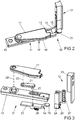
- the locking device 10 is in FIG. 2 enlarged and shown in perspective.
- the frame-side fitting part 11 has a longitudinally displaceably guided bolt 13 with a bend 14. In the intended preferred mounting position, the bend 14 leads the free end 15 of the bolt 13 on the in FIG. 1 illustrated horizontal axis 7.
- the movement of the bolt 13 is generated in the assembled state via a control device 16 in dependence on the position of the wing 2 relative to the frame 1.
- the control device 16 has a pivot lever 17 with a button 18.
- the frame-side fitting part 11 has a base body 19 to be screwed to the frame 19 for supporting the pivot lever 17 and for guiding the bolt 13. In the illustrated position, the pivot lever 17 is above the base body Pivoted 19 and the bolt 13 fully extended.
- the wing-side fitting part has a pocket 20.
- the pocket 20 receives the free end 15 of the latch 13.
- the locking device 10 prevents a lever in the FIG. 1 illustrated wing 2 transverse to the horizontal axis. 7
- FIG. 3 shows in an exploded view of the individual components of the locking device 10 FIG. 2 ,
- the control lever 16 has a control lever 21 arranged below the pivot lever 17.
- the control lever 21 has a bearing 22 in the bolt 13 and a bearing 23 in the pivot lever 17. Swivel lever 17 and control lever 21 together form a toggle, so that upon deflection of the pivot lever 17 the toggle lever is moved in an extended or angled position. Thus, the latch 13 is extended or retracted into the main body 19.
- FIG. 3 shows that the pocket 20 is bounded symmetrically by a bracket 24 and is mounted on a base 25 parallel to the one in FIG FIG. 1 shown vertical axis 8 is guided.
- Latch 13 and pocket 20 are each biased by a spring element 26, 27 in a basic position.
- the height of the pocket 20 may also be adjustable by an adjusting means.
- the locking device 10 can also be unlocked when the in FIG. 1 illustrated wing 2 is rotated by the frame 1 about the vertical axis 8 away.
- the bolt 13 is pulled by the force of the spring element 26 out of the pocket 20 and the pivot lever 17 is deflected with the button 18, so that the toggle lever of the pivot lever 17 and the control lever 21 is bent.
- a renewed movement of the wing 2 against the frame 1 leads to a depression of the button 18 and the associated extension of the toggle lever against the Force of the spring element 26.
- the locking device 10 is moved back into the locking position.
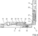
- FIG. 4 shows a sectional view of the locking device 10 FIG. 2 , Here it can be seen that the control lever 21 and the pivot lever 17 are sandwiched one above the other.
- the pivot lever 17 has a reinforcement 29 between a bearing 28 in the base body 19 and its bearing 23 on the control lever 21.
- the reinforcement 29 is slightly thicker than the height of the control lever 21st
Landscapes
- Engineering & Computer Science (AREA)
- Structural Engineering (AREA)
- Mechanical Engineering (AREA)
- Lock And Its Accessories (AREA)
Priority Applications (2)
| Application Number | Priority Date | Filing Date | Title |
|---|---|---|---|
| PL18160188T PL3379008T3 (pl) | 2017-03-20 | 2018-03-06 | Urządzenie ryglujące |
| SI201830010T SI3379008T1 (sl) | 2017-03-20 | 2018-03-06 | Zaporna naprava |
Applications Claiming Priority (1)
| Application Number | Priority Date | Filing Date | Title |
|---|---|---|---|
| DE102017204552.3A DE102017204552A1 (de) | 2017-03-20 | 2017-03-20 | Verriegelungseinrichtung |
Publications (2)
| Publication Number | Publication Date |
|---|---|
| EP3379008A1 true EP3379008A1 (fr) | 2018-09-26 |
| EP3379008B1 EP3379008B1 (fr) | 2019-09-18 |
Family
ID=61580973
Family Applications (1)
| Application Number | Title | Priority Date | Filing Date |
|---|---|---|---|
| EP18160188.1A Active EP3379008B1 (fr) | 2017-03-20 | 2018-03-06 | Dispositif de verrouillage |
Country Status (4)
| Country | Link |
|---|---|
| EP (1) | EP3379008B1 (fr) |
| DE (1) | DE102017204552A1 (fr) |
| PL (1) | PL3379008T3 (fr) |
| SI (1) | SI3379008T1 (fr) |
Citations (7)
| Publication number | Priority date | Publication date | Assignee | Title |
|---|---|---|---|---|
| DE29605592U1 (de) * | 1996-03-26 | 1997-07-24 | Mayer & Co., Salzburg | Aufdrücksperre |
| GB2324331A (en) * | 1997-04-15 | 1998-10-21 | Ian Alexander Gordon | Window lock automatically releasable on opening of the window |
| EP1728947A2 (fr) * | 2005-06-01 | 2006-12-06 | Aug. Winkhaus GmbH & Co. KG | Pêne de verrouillage et gâche pour une ferrure à crémone |
| DE202008012837U1 (de) * | 2008-09-27 | 2010-03-04 | Haverkamp, Bernhard | Fenster mit verriegelbarem Beschlag |
| DE102008047194A1 (de) * | 2008-09-15 | 2010-04-15 | ABUS August Bremicker Söhne KG | Verriegelungseinheit für Fenster- oder Türflügel |
| EP2324331A1 (fr) | 2008-09-12 | 2011-05-25 | Waters Technologies Corporation | Profil d'admission permettant l utilisation optimisée des caractéristiques d'un moteur |
| DE102012103277A1 (de) * | 2012-04-16 | 2013-10-17 | REGEL-air Becks GmbH & Co. KG | Einbruchshemmende Verriegelungseinheit |
-
2017
- 2017-03-20 DE DE102017204552.3A patent/DE102017204552A1/de not_active Withdrawn
-
2018
- 2018-03-06 SI SI201830010T patent/SI3379008T1/sl unknown
- 2018-03-06 PL PL18160188T patent/PL3379008T3/pl unknown
- 2018-03-06 EP EP18160188.1A patent/EP3379008B1/fr active Active
Patent Citations (7)
| Publication number | Priority date | Publication date | Assignee | Title |
|---|---|---|---|---|
| DE29605592U1 (de) * | 1996-03-26 | 1997-07-24 | Mayer & Co., Salzburg | Aufdrücksperre |
| GB2324331A (en) * | 1997-04-15 | 1998-10-21 | Ian Alexander Gordon | Window lock automatically releasable on opening of the window |
| EP1728947A2 (fr) * | 2005-06-01 | 2006-12-06 | Aug. Winkhaus GmbH & Co. KG | Pêne de verrouillage et gâche pour une ferrure à crémone |
| EP2324331A1 (fr) | 2008-09-12 | 2011-05-25 | Waters Technologies Corporation | Profil d'admission permettant l utilisation optimisée des caractéristiques d'un moteur |
| DE102008047194A1 (de) * | 2008-09-15 | 2010-04-15 | ABUS August Bremicker Söhne KG | Verriegelungseinheit für Fenster- oder Türflügel |
| DE202008012837U1 (de) * | 2008-09-27 | 2010-03-04 | Haverkamp, Bernhard | Fenster mit verriegelbarem Beschlag |
| DE102012103277A1 (de) * | 2012-04-16 | 2013-10-17 | REGEL-air Becks GmbH & Co. KG | Einbruchshemmende Verriegelungseinheit |
Also Published As
| Publication number | Publication date |
|---|---|
| DE102017204552A1 (de) | 2018-09-20 |
| EP3379008B1 (fr) | 2019-09-18 |
| PL3379008T3 (pl) | 2020-03-31 |
| SI3379008T1 (sl) | 2019-12-31 |
Similar Documents
| Publication | Publication Date | Title |
|---|---|---|
| EP3835526B1 (fr) | Système de battant coulissant et tournant | |
| DE202021102238U1 (de) | Drehkippfenster und Beschlaganordnung | |
| DE8528395U1 (de) | Schiebeschwenktür | |
| EP3183408B1 (fr) | Élément de commande pour système de ferrure | |
| DE102015100547A1 (de) | Ausstellvorrichtung für ein Fenster oder eine Tür mit einer Energiespeichereinrichtung | |
| EP3168401B1 (fr) | Système de compas de projection et porte coulissante ou fenêtre coulissante dotée d'un tel système de compas de projection | |
| EP3379008B1 (fr) | Dispositif de verrouillage | |
| EP3749822B1 (fr) | Ferrure d'appui pour un battant basculant d'une fenêtre ou d'une porte | |
| EP2369111B1 (fr) | Palier d'angle caché | |
| EP1691000A1 (fr) | Fenêtre de toit basculante pivotante | |
| DE2658626B2 (de) | Schaltsperre für Treibstangenbeschläge | |
| EP4336006A1 (fr) | Ferrue pour un vantail pivotant contre un cadre | |
| EP2740872B1 (fr) | Palier d'angle prévu pour l'agencement recouvert | |
| EP1321615B1 (fr) | Fenêtre oscillobattante | |
| EP4119755A1 (fr) | Crémone basculante pré-rotative pour un vantail pivotant contre un cadre | |
| DE102004060717B4 (de) | Verschluss zur Verriegelung eines Flügels in einem Rahmen eines Fensters | |
| EP3470606B1 (fr) | Serrure pour ferrure à crémone | |
| DE102004049068A1 (de) | Schnäpper für Balkon-oder Terrassentüren | |
| DE102014221290B3 (de) | Verbindungsanordnung für ein Fenster, eine Tür oder dergleichen | |
| EP3088639B1 (fr) | Dispositif destine a aligner des parties de ferrure a disposer en regard l'une de l'autre | |
| EP1580380A2 (fr) | Ferrure de crémone | |
| DE102014221292B4 (de) | Beschlaganordnung zur Öffnungsunterstützung eines Flügels eines Fensters oder einer Tür | |
| EP3715564B1 (fr) | Fixation d'une ferrure de crémone | |
| EP2228509B1 (fr) | Ensemble de compas d'un dispositif de fermeture destiné à la fermeture au moins partielle d'une fenêtre ou porte oscillo-battante | |
| DE102023210536A1 (de) | Einrichtung zur Kopplung eines Schiebebeschlagbauteils |
Legal Events
| Date | Code | Title | Description |
|---|---|---|---|
| PUAI | Public reference made under article 153(3) epc to a published international application that has entered the european phase |
Free format text: ORIGINAL CODE: 0009012 |
|
| STAA | Information on the status of an ep patent application or granted ep patent |
Free format text: STATUS: THE APPLICATION HAS BEEN PUBLISHED |
|
| AK | Designated contracting states |
Kind code of ref document: A1 Designated state(s): AL AT BE BG CH CY CZ DE DK EE ES FI FR GB GR HR HU IE IS IT LI LT LU LV MC MK MT NL NO PL PT RO RS SE SI SK SM TR |
|
| AX | Request for extension of the european patent |
Extension state: BA ME |
|
| STAA | Information on the status of an ep patent application or granted ep patent |
Free format text: STATUS: REQUEST FOR EXAMINATION WAS MADE |
|
| 17P | Request for examination filed |
Effective date: 20190227 |
|
| RBV | Designated contracting states (corrected) |
Designated state(s): AL AT BE BG CH CY CZ DE DK EE ES FI FR GB GR HR HU IE IS IT LI LT LU LV MC MK MT NL NO PL PT RO RS SE SI SK SM TR |
|
| GRAP | Despatch of communication of intention to grant a patent |
Free format text: ORIGINAL CODE: EPIDOSNIGR1 |
|
| STAA | Information on the status of an ep patent application or granted ep patent |
Free format text: STATUS: GRANT OF PATENT IS INTENDED |
|
| RIC1 | Information provided on ipc code assigned before grant |
Ipc: E05B 15/10 20060101ALI20190408BHEP Ipc: E05B 63/00 20060101ALI20190408BHEP Ipc: E05D 15/526 20060101ALN20190408BHEP Ipc: E05B 63/04 20060101ALI20190408BHEP Ipc: E05C 1/06 20060101AFI20190408BHEP |
|
| INTG | Intention to grant announced |
Effective date: 20190507 |
|
| GRAS | Grant fee paid |
Free format text: ORIGINAL CODE: EPIDOSNIGR3 |
|
| GRAA | (expected) grant |
Free format text: ORIGINAL CODE: 0009210 |
|
| STAA | Information on the status of an ep patent application or granted ep patent |
Free format text: STATUS: THE PATENT HAS BEEN GRANTED |
|
| AK | Designated contracting states |
Kind code of ref document: B1 Designated state(s): AL AT BE BG CH CY CZ DE DK EE ES FI FR GB GR HR HU IE IS IT LI LT LU LV MC MK MT NL NO PL PT RO RS SE SI SK SM TR |
|
| REG | Reference to a national code |
Ref country code: GB Ref legal event code: FG4D Free format text: NOT ENGLISH |
|
| REG | Reference to a national code |
Ref country code: CH Ref legal event code: EP |
|
| REG | Reference to a national code |
Ref country code: DE Ref legal event code: R096 Ref document number: 502018000222 Country of ref document: DE |
|
| REG | Reference to a national code |
Ref country code: AT Ref legal event code: REF Ref document number: 1181492 Country of ref document: AT Kind code of ref document: T Effective date: 20191015 |
|
| REG | Reference to a national code |
Ref country code: IE Ref legal event code: FG4D Free format text: LANGUAGE OF EP DOCUMENT: GERMAN |
|
| REG | Reference to a national code |
Ref country code: NL Ref legal event code: MP Effective date: 20190918 |
|
| PG25 | Lapsed in a contracting state [announced via postgrant information from national office to epo] |
Ref country code: NO Free format text: LAPSE BECAUSE OF FAILURE TO SUBMIT A TRANSLATION OF THE DESCRIPTION OR TO PAY THE FEE WITHIN THE PRESCRIBED TIME-LIMIT Effective date: 20191218 Ref country code: FI Free format text: LAPSE BECAUSE OF FAILURE TO SUBMIT A TRANSLATION OF THE DESCRIPTION OR TO PAY THE FEE WITHIN THE PRESCRIBED TIME-LIMIT Effective date: 20190918 Ref country code: LT Free format text: LAPSE BECAUSE OF FAILURE TO SUBMIT A TRANSLATION OF THE DESCRIPTION OR TO PAY THE FEE WITHIN THE PRESCRIBED TIME-LIMIT Effective date: 20190918 Ref country code: HR Free format text: LAPSE BECAUSE OF FAILURE TO SUBMIT A TRANSLATION OF THE DESCRIPTION OR TO PAY THE FEE WITHIN THE PRESCRIBED TIME-LIMIT Effective date: 20190918 Ref country code: BG Free format text: LAPSE BECAUSE OF FAILURE TO SUBMIT A TRANSLATION OF THE DESCRIPTION OR TO PAY THE FEE WITHIN THE PRESCRIBED TIME-LIMIT Effective date: 20191218 Ref country code: SE Free format text: LAPSE BECAUSE OF FAILURE TO SUBMIT A TRANSLATION OF THE DESCRIPTION OR TO PAY THE FEE WITHIN THE PRESCRIBED TIME-LIMIT Effective date: 20190918 |
|
| REG | Reference to a national code |
Ref country code: LT Ref legal event code: MG4D |
|
| PG25 | Lapsed in a contracting state [announced via postgrant information from national office to epo] |
Ref country code: RS Free format text: LAPSE BECAUSE OF FAILURE TO SUBMIT A TRANSLATION OF THE DESCRIPTION OR TO PAY THE FEE WITHIN THE PRESCRIBED TIME-LIMIT Effective date: 20190918 Ref country code: GR Free format text: LAPSE BECAUSE OF FAILURE TO SUBMIT A TRANSLATION OF THE DESCRIPTION OR TO PAY THE FEE WITHIN THE PRESCRIBED TIME-LIMIT Effective date: 20191219 Ref country code: AL Free format text: LAPSE BECAUSE OF FAILURE TO SUBMIT A TRANSLATION OF THE DESCRIPTION OR TO PAY THE FEE WITHIN THE PRESCRIBED TIME-LIMIT Effective date: 20190918 Ref country code: LV Free format text: LAPSE BECAUSE OF FAILURE TO SUBMIT A TRANSLATION OF THE DESCRIPTION OR TO PAY THE FEE WITHIN THE PRESCRIBED TIME-LIMIT Effective date: 20190918 |
|
| REG | Reference to a national code |
Ref country code: ES Ref legal event code: FG2A Ref document number: 2748894 Country of ref document: ES Kind code of ref document: T3 Effective date: 20200318 |
|
| PG25 | Lapsed in a contracting state [announced via postgrant information from national office to epo] |
Ref country code: RO Free format text: LAPSE BECAUSE OF FAILURE TO SUBMIT A TRANSLATION OF THE DESCRIPTION OR TO PAY THE FEE WITHIN THE PRESCRIBED TIME-LIMIT Effective date: 20190918 Ref country code: NL Free format text: LAPSE BECAUSE OF FAILURE TO SUBMIT A TRANSLATION OF THE DESCRIPTION OR TO PAY THE FEE WITHIN THE PRESCRIBED TIME-LIMIT Effective date: 20190918 Ref country code: PT Free format text: LAPSE BECAUSE OF FAILURE TO SUBMIT A TRANSLATION OF THE DESCRIPTION OR TO PAY THE FEE WITHIN THE PRESCRIBED TIME-LIMIT Effective date: 20200120 Ref country code: EE Free format text: LAPSE BECAUSE OF FAILURE TO SUBMIT A TRANSLATION OF THE DESCRIPTION OR TO PAY THE FEE WITHIN THE PRESCRIBED TIME-LIMIT Effective date: 20190918 |
|
| PG25 | Lapsed in a contracting state [announced via postgrant information from national office to epo] |
Ref country code: SM Free format text: LAPSE BECAUSE OF FAILURE TO SUBMIT A TRANSLATION OF THE DESCRIPTION OR TO PAY THE FEE WITHIN THE PRESCRIBED TIME-LIMIT Effective date: 20190918 Ref country code: SK Free format text: LAPSE BECAUSE OF FAILURE TO SUBMIT A TRANSLATION OF THE DESCRIPTION OR TO PAY THE FEE WITHIN THE PRESCRIBED TIME-LIMIT Effective date: 20190918 Ref country code: IS Free format text: LAPSE BECAUSE OF FAILURE TO SUBMIT A TRANSLATION OF THE DESCRIPTION OR TO PAY THE FEE WITHIN THE PRESCRIBED TIME-LIMIT Effective date: 20200224 Ref country code: CZ Free format text: LAPSE BECAUSE OF FAILURE TO SUBMIT A TRANSLATION OF THE DESCRIPTION OR TO PAY THE FEE WITHIN THE PRESCRIBED TIME-LIMIT Effective date: 20190918 |
|
| REG | Reference to a national code |
Ref country code: DE Ref legal event code: R097 Ref document number: 502018000222 Country of ref document: DE |
|
| PLBE | No opposition filed within time limit |
Free format text: ORIGINAL CODE: 0009261 |
|
| STAA | Information on the status of an ep patent application or granted ep patent |
Free format text: STATUS: NO OPPOSITION FILED WITHIN TIME LIMIT |
|
| PG2D | Information on lapse in contracting state deleted |
Ref country code: IS |
|
| PG25 | Lapsed in a contracting state [announced via postgrant information from national office to epo] |
Ref country code: DK Free format text: LAPSE BECAUSE OF FAILURE TO SUBMIT A TRANSLATION OF THE DESCRIPTION OR TO PAY THE FEE WITHIN THE PRESCRIBED TIME-LIMIT Effective date: 20190918 Ref country code: IS Free format text: LAPSE BECAUSE OF FAILURE TO SUBMIT A TRANSLATION OF THE DESCRIPTION OR TO PAY THE FEE WITHIN THE PRESCRIBED TIME-LIMIT Effective date: 20200119 |
|
| 26N | No opposition filed |
Effective date: 20200619 |
|
| PG25 | Lapsed in a contracting state [announced via postgrant information from national office to epo] |
Ref country code: MC Free format text: LAPSE BECAUSE OF FAILURE TO SUBMIT A TRANSLATION OF THE DESCRIPTION OR TO PAY THE FEE WITHIN THE PRESCRIBED TIME-LIMIT Effective date: 20190918 |
|
| PG25 | Lapsed in a contracting state [announced via postgrant information from national office to epo] |
Ref country code: LU Free format text: LAPSE BECAUSE OF NON-PAYMENT OF DUE FEES Effective date: 20200306 |
|
| PG25 | Lapsed in a contracting state [announced via postgrant information from national office to epo] |
Ref country code: IE Free format text: LAPSE BECAUSE OF NON-PAYMENT OF DUE FEES Effective date: 20200306 |
|
| REG | Reference to a national code |
Ref country code: CH Ref legal event code: PL |
|
| PG25 | Lapsed in a contracting state [announced via postgrant information from national office to epo] |
Ref country code: CH Free format text: LAPSE BECAUSE OF NON-PAYMENT OF DUE FEES Effective date: 20210331 Ref country code: LI Free format text: LAPSE BECAUSE OF NON-PAYMENT OF DUE FEES Effective date: 20210331 |
|
| PG25 | Lapsed in a contracting state [announced via postgrant information from national office to epo] |
Ref country code: MT Free format text: LAPSE BECAUSE OF FAILURE TO SUBMIT A TRANSLATION OF THE DESCRIPTION OR TO PAY THE FEE WITHIN THE PRESCRIBED TIME-LIMIT Effective date: 20190918 Ref country code: CY Free format text: LAPSE BECAUSE OF FAILURE TO SUBMIT A TRANSLATION OF THE DESCRIPTION OR TO PAY THE FEE WITHIN THE PRESCRIBED TIME-LIMIT Effective date: 20190918 |
|
| PG25 | Lapsed in a contracting state [announced via postgrant information from national office to epo] |
Ref country code: MK Free format text: LAPSE BECAUSE OF FAILURE TO SUBMIT A TRANSLATION OF THE DESCRIPTION OR TO PAY THE FEE WITHIN THE PRESCRIBED TIME-LIMIT Effective date: 20190918 |
|
| GBPC | Gb: european patent ceased through non-payment of renewal fee |
Effective date: 20220306 |
|
| PG25 | Lapsed in a contracting state [announced via postgrant information from national office to epo] |
Ref country code: GB Free format text: LAPSE BECAUSE OF NON-PAYMENT OF DUE FEES Effective date: 20220306 |
|
| P01 | Opt-out of the competence of the unified patent court (upc) registered |
Effective date: 20230516 |
|
| REG | Reference to a national code |
Ref country code: DE Ref legal event code: R081 Ref document number: 502018000222 Country of ref document: DE Owner name: AUG. WINKHAUS SE & CO. KG, DE Free format text: FORMER OWNER: AUG. WINKHAUS GMBH & CO. KG, 48291 TELGTE, DE Ref country code: DE Ref legal event code: R081 Ref document number: 502018000222 Country of ref document: DE Owner name: AUG. WINKHAUS SE, DE Free format text: FORMER OWNER: AUG. WINKHAUS GMBH & CO. KG, 48291 TELGTE, DE |
|
| PGFP | Annual fee paid to national office [announced via postgrant information from national office to epo] |
Ref country code: ES Payment date: 20250416 Year of fee payment: 8 |
|
| PGFP | Annual fee paid to national office [announced via postgrant information from national office to epo] |
Ref country code: IT Payment date: 20250331 Year of fee payment: 8 |
|
| REG | Reference to a national code |
Ref country code: DE Ref legal event code: R081 Ref document number: 502018000222 Country of ref document: DE Owner name: AUG. WINKHAUS SE, DE Free format text: FORMER OWNER: AUG. WINKHAUS SE & CO. KG, 48291 TELGTE, DE |
|
| PGFP | Annual fee paid to national office [announced via postgrant information from national office to epo] |
Ref country code: DE Payment date: 20260320 Year of fee payment: 9 |
|
| PGFP | Annual fee paid to national office [announced via postgrant information from national office to epo] |
Ref country code: AT Payment date: 20260319 Year of fee payment: 9 |
|
| PGFP | Annual fee paid to national office [announced via postgrant information from national office to epo] |
Ref country code: BE Payment date: 20260323 Year of fee payment: 9 |
|
| PGFP | Annual fee paid to national office [announced via postgrant information from national office to epo] |
Ref country code: FR Payment date: 20260324 Year of fee payment: 9 |
|
| PGFP | Annual fee paid to national office [announced via postgrant information from national office to epo] |
Ref country code: TR Payment date: 20260227 Year of fee payment: 9 |
|
| PGFP | Annual fee paid to national office [announced via postgrant information from national office to epo] |
Ref country code: PL Payment date: 20260227 Year of fee payment: 9 |
|
| PGFP | Annual fee paid to national office [announced via postgrant information from national office to epo] |
Ref country code: SI Payment date: 20260223 Year of fee payment: 9 |