EP3379114A1 - Joint de culasse - Google Patents
Joint de culasse Download PDFInfo
- Publication number
- EP3379114A1 EP3379114A1 EP16866469.6A EP16866469A EP3379114A1 EP 3379114 A1 EP3379114 A1 EP 3379114A1 EP 16866469 A EP16866469 A EP 16866469A EP 3379114 A1 EP3379114 A1 EP 3379114A1
- Authority
- EP
- European Patent Office
- Prior art keywords
- bore
- plate
- cylinder head
- head gasket
- hole
- Prior art date
- Legal status (The legal status is an assumption and is not a legal conclusion. Google has not performed a legal analysis and makes no representation as to the accuracy of the status listed.)
- Withdrawn
Links
- 239000011324 bead Substances 0.000 claims description 31
- 229920001971 elastomer Polymers 0.000 claims description 30
- 230000002093 peripheral effect Effects 0.000 claims description 29
- 239000013013 elastic material Substances 0.000 claims description 22
- 239000000463 material Substances 0.000 claims description 14
- 229910052751 metal Inorganic materials 0.000 claims description 12
- 239000002184 metal Substances 0.000 claims description 12
- XLYOFNOQVPJJNP-UHFFFAOYSA-N water Substances O XLYOFNOQVPJJNP-UHFFFAOYSA-N 0.000 claims description 6
- 238000007789 sealing Methods 0.000 description 9
- 229920000459 Nitrile rubber Polymers 0.000 description 6
- 230000000694 effects Effects 0.000 description 6
- 229910052782 aluminium Inorganic materials 0.000 description 4
- XAGFODPZIPBFFR-UHFFFAOYSA-N aluminium Chemical compound [Al] XAGFODPZIPBFFR-UHFFFAOYSA-N 0.000 description 4
- 229920001973 fluoroelastomer Polymers 0.000 description 4
- 239000000446 fuel Substances 0.000 description 4
- RYGMFSIKBFXOCR-UHFFFAOYSA-N Copper Chemical compound [Cu] RYGMFSIKBFXOCR-UHFFFAOYSA-N 0.000 description 3
- 229910000881 Cu alloy Inorganic materials 0.000 description 3
- 229910052802 copper Inorganic materials 0.000 description 3
- 239000010949 copper Substances 0.000 description 3
- XEEYBQQBJWHFJM-UHFFFAOYSA-N Iron Chemical compound [Fe] XEEYBQQBJWHFJM-UHFFFAOYSA-N 0.000 description 2
- 238000005452 bending Methods 0.000 description 2
- 230000006835 compression Effects 0.000 description 2
- 238000007906 compression Methods 0.000 description 2
- 238000009413 insulation Methods 0.000 description 2
- 238000004519 manufacturing process Methods 0.000 description 2
- 239000007769 metal material Substances 0.000 description 2
- 239000000203 mixture Substances 0.000 description 2
- 238000000465 moulding Methods 0.000 description 2
- 229920002943 EPDM rubber Polymers 0.000 description 1
- 229920000181 Ethylene propylene rubber Polymers 0.000 description 1
- 229910000640 Fe alloy Inorganic materials 0.000 description 1
- 229920000800 acrylic rubber Polymers 0.000 description 1
- 230000015572 biosynthetic process Effects 0.000 description 1
- 238000002485 combustion reaction Methods 0.000 description 1
- 239000000498 cooling water Substances 0.000 description 1
- 238000004132 cross linking Methods 0.000 description 1
- 238000006073 displacement reaction Methods 0.000 description 1
- 238000009826 distribution Methods 0.000 description 1
- 230000008030 elimination Effects 0.000 description 1
- 238000003379 elimination reaction Methods 0.000 description 1
- 230000002349 favourable effect Effects 0.000 description 1
- 229910052742 iron Inorganic materials 0.000 description 1
- 238000000034 method Methods 0.000 description 1
- 229920000058 polyacrylate Polymers 0.000 description 1
- 229920002379 silicone rubber Polymers 0.000 description 1
- 239000004945 silicone rubber Substances 0.000 description 1
- 239000010935 stainless steel Substances 0.000 description 1
- 229910001220 stainless steel Inorganic materials 0.000 description 1
- 238000004073 vulcanization Methods 0.000 description 1
- 238000003466 welding Methods 0.000 description 1
Images



Classifications
-
- F—MECHANICAL ENGINEERING; LIGHTING; HEATING; WEAPONS; BLASTING
- F02—COMBUSTION ENGINES; HOT-GAS OR COMBUSTION-PRODUCT ENGINE PLANTS
- F02F—CYLINDERS, PISTONS OR CASINGS, FOR COMBUSTION ENGINES; ARRANGEMENTS OF SEALINGS IN COMBUSTION ENGINES
- F02F11/00—Arrangements of sealings in combustion engines
- F02F11/002—Arrangements of sealings in combustion engines involving cylinder heads
-
- F—MECHANICAL ENGINEERING; LIGHTING; HEATING; WEAPONS; BLASTING
- F16—ENGINEERING ELEMENTS AND UNITS; GENERAL MEASURES FOR PRODUCING AND MAINTAINING EFFECTIVE FUNCTIONING OF MACHINES OR INSTALLATIONS; THERMAL INSULATION IN GENERAL
- F16J—PISTONS; CYLINDERS; SEALINGS
- F16J15/00—Sealings
- F16J15/02—Sealings between relatively-stationary surfaces
- F16J15/06—Sealings between relatively-stationary surfaces with solid packing compressed between sealing surfaces
- F16J15/08—Sealings between relatively-stationary surfaces with solid packing compressed between sealing surfaces with exclusively metal packing
- F16J15/0818—Flat gaskets
-
- F—MECHANICAL ENGINEERING; LIGHTING; HEATING; WEAPONS; BLASTING
- F02—COMBUSTION ENGINES; HOT-GAS OR COMBUSTION-PRODUCT ENGINE PLANTS
- F02F—CYLINDERS, PISTONS OR CASINGS, FOR COMBUSTION ENGINES; ARRANGEMENTS OF SEALINGS IN COMBUSTION ENGINES
- F02F11/00—Arrangements of sealings in combustion engines
-
- F—MECHANICAL ENGINEERING; LIGHTING; HEATING; WEAPONS; BLASTING
- F16—ENGINEERING ELEMENTS AND UNITS; GENERAL MEASURES FOR PRODUCING AND MAINTAINING EFFECTIVE FUNCTIONING OF MACHINES OR INSTALLATIONS; THERMAL INSULATION IN GENERAL
- F16J—PISTONS; CYLINDERS; SEALINGS
- F16J15/00—Sealings
- F16J15/02—Sealings between relatively-stationary surfaces
- F16J15/06—Sealings between relatively-stationary surfaces with solid packing compressed between sealing surfaces
- F16J15/10—Sealings between relatively-stationary surfaces with solid packing compressed between sealing surfaces with non-metallic packing
- F16J15/12—Sealings between relatively-stationary surfaces with solid packing compressed between sealing surfaces with non-metallic packing with metal reinforcement or covering
- F16J15/121—Sealings between relatively-stationary surfaces with solid packing compressed between sealing surfaces with non-metallic packing with metal reinforcement or covering with metal reinforcement
- F16J15/122—Sealings between relatively-stationary surfaces with solid packing compressed between sealing surfaces with non-metallic packing with metal reinforcement or covering with metal reinforcement generally parallel to the surfaces
-
- F—MECHANICAL ENGINEERING; LIGHTING; HEATING; WEAPONS; BLASTING
- F16—ENGINEERING ELEMENTS AND UNITS; GENERAL MEASURES FOR PRODUCING AND MAINTAINING EFFECTIVE FUNCTIONING OF MACHINES OR INSTALLATIONS; THERMAL INSULATION IN GENERAL
- F16J—PISTONS; CYLINDERS; SEALINGS
- F16J15/00—Sealings
- F16J15/02—Sealings between relatively-stationary surfaces
- F16J15/06—Sealings between relatively-stationary surfaces with solid packing compressed between sealing surfaces
- F16J15/10—Sealings between relatively-stationary surfaces with solid packing compressed between sealing surfaces with non-metallic packing
- F16J15/12—Sealings between relatively-stationary surfaces with solid packing compressed between sealing surfaces with non-metallic packing with metal reinforcement or covering
- F16J15/121—Sealings between relatively-stationary surfaces with solid packing compressed between sealing surfaces with non-metallic packing with metal reinforcement or covering with metal reinforcement
- F16J15/125—Sealings between relatively-stationary surfaces with solid packing compressed between sealing surfaces with non-metallic packing with metal reinforcement or covering with metal reinforcement generally perpendicular to the surfaces
-
- F—MECHANICAL ENGINEERING; LIGHTING; HEATING; WEAPONS; BLASTING
- F16—ENGINEERING ELEMENTS AND UNITS; GENERAL MEASURES FOR PRODUCING AND MAINTAINING EFFECTIVE FUNCTIONING OF MACHINES OR INSTALLATIONS; THERMAL INSULATION IN GENERAL
- F16J—PISTONS; CYLINDERS; SEALINGS
- F16J15/00—Sealings
- F16J15/02—Sealings between relatively-stationary surfaces
- F16J15/06—Sealings between relatively-stationary surfaces with solid packing compressed between sealing surfaces
- F16J15/10—Sealings between relatively-stationary surfaces with solid packing compressed between sealing surfaces with non-metallic packing
- F16J15/12—Sealings between relatively-stationary surfaces with solid packing compressed between sealing surfaces with non-metallic packing with metal reinforcement or covering
- F16J15/121—Sealings between relatively-stationary surfaces with solid packing compressed between sealing surfaces with non-metallic packing with metal reinforcement or covering with metal reinforcement
- F16J15/127—Sealings between relatively-stationary surfaces with solid packing compressed between sealing surfaces with non-metallic packing with metal reinforcement or covering with metal reinforcement the reinforcement being a compression stopper
-
- F—MECHANICAL ENGINEERING; LIGHTING; HEATING; WEAPONS; BLASTING
- F16—ENGINEERING ELEMENTS AND UNITS; GENERAL MEASURES FOR PRODUCING AND MAINTAINING EFFECTIVE FUNCTIONING OF MACHINES OR INSTALLATIONS; THERMAL INSULATION IN GENERAL
- F16J—PISTONS; CYLINDERS; SEALINGS
- F16J15/00—Sealings
- F16J15/02—Sealings between relatively-stationary surfaces
- F16J15/06—Sealings between relatively-stationary surfaces with solid packing compressed between sealing surfaces
- F16J15/08—Sealings between relatively-stationary surfaces with solid packing compressed between sealing surfaces with exclusively metal packing
- F16J15/0818—Flat gaskets
- F16J2015/0856—Flat gaskets with a non-metallic coating or strip
-
- F—MECHANICAL ENGINEERING; LIGHTING; HEATING; WEAPONS; BLASTING
- F16—ENGINEERING ELEMENTS AND UNITS; GENERAL MEASURES FOR PRODUCING AND MAINTAINING EFFECTIVE FUNCTIONING OF MACHINES OR INSTALLATIONS; THERMAL INSULATION IN GENERAL
- F16J—PISTONS; CYLINDERS; SEALINGS
- F16J15/00—Sealings
- F16J15/02—Sealings between relatively-stationary surfaces
- F16J15/06—Sealings between relatively-stationary surfaces with solid packing compressed between sealing surfaces
- F16J15/08—Sealings between relatively-stationary surfaces with solid packing compressed between sealing surfaces with exclusively metal packing
- F16J15/0818—Flat gaskets
- F16J2015/0862—Flat gaskets with a bore ring
-
- F—MECHANICAL ENGINEERING; LIGHTING; HEATING; WEAPONS; BLASTING
- F16—ENGINEERING ELEMENTS AND UNITS; GENERAL MEASURES FOR PRODUCING AND MAINTAINING EFFECTIVE FUNCTIONING OF MACHINES OR INSTALLATIONS; THERMAL INSULATION IN GENERAL
- F16J—PISTONS; CYLINDERS; SEALINGS
- F16J15/00—Sealings
- F16J15/02—Sealings between relatively-stationary surfaces
- F16J15/06—Sealings between relatively-stationary surfaces with solid packing compressed between sealing surfaces
- F16J15/08—Sealings between relatively-stationary surfaces with solid packing compressed between sealing surfaces with exclusively metal packing
- F16J15/0818—Flat gaskets
- F16J2015/0868—Aspects not related to the edges of the gasket
Definitions
- the present invention relates to a cylinder head gasket, and more particularly, to a cylinder head gasket where heat conduction through the gasket in a plane direction can be suppressed.
- An engine of an automobile or the like includes a cylinder block having cylinder bores and a cylinder head mounted on the cylinder block.
- a cylinder head gasket is mounted between the cylinder block and the cylinder head thus providing sealing between the cylinder block and the cylinder head.
- an air-fuel mixture is combusted in the cylinder bores formed in the cylinder block so that the cylinder block reaches an extremely high temperature.
- the cylinder head gasket transfers heat of the cylinder block to the cylinder head thus reducing a temperature difference between the cylinder block and the cylinder head and hence, it is possible to suppress the generation of stress caused by a temperature difference between the cylinder block and the cylinder head whereby stable sealing properties can be maintained.
- Heat transferred from the cylinder block to the cylinder head gasket reaches a high temperature particularly in the peripheries of bore holes formed corresponding to the cylinder bores where an air-fuel mixture is combusted, and gradually lowers as a distance is increased from the bore holes.
- a cylinder head gasket having the following configuration. That is, the cylinder head gasket is formed using a metal plate. Bore holes are formed in the metal plate, and a high-heat-conductive peripheral edge member having high heat conductivity is integrally formed with peripheral edge portions of the bore holes by welding or the like. With such a configuration, heat in the peripheries of the bore holes is actively transferred to the cylinder head thus eliminating a temperature difference between the cylinder block and the cylinder head at an early stage (patent document 1).
- Patent Document 1 JP-A-2011-144912
- heat of the cylinder block is transferred not only to the cylinder head through the cylinder head gasket, but heat transferred from bore holes is also transferred through the cylinder head gasket in a plane direction.
- bore-hole plates, an intermediate plate, and a main plate are separated from each other without being in contact with each other, while being connected with each other with a heat insulating member interposed between each bore-hole plate and the intermediate plate and between the intermediate plate and the main plate.
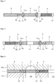
- Figure 1 is a plan view showing one example of a cylinder head gasket according to the present invention.
- Figure 2 is a cross-sectional view taken along a line (ii)-(ii) in Figure 1 .
- Figure 3 is a cross-sectional view taken along a line (iii)-(iii) in Figure 1 .
- Figure 4 is a cross-sectional view taken along a line (ii)-(ii) in Figure 1 showing a state where the cylinder head gasket shown in Figure 1 is mounted between a cylinder block and a cylinder head.
- a cylinder head gasket 1 is a gasket mounted between a cylinder block 100 and a cylinder head 200 of an engine.
- the cylinder head gasket 1 prefferably includes at least a bore-hole plate 3 and a main plate 5.
- the bore-hole plate 3 and the main plate 5 are separated from each other without being in contact with each other.
- an intermediate plate 4 is disposed between the main plate 5 and the bore-hole plates 3, and the intermediate plate 4 corresponds to a water jacket formed around cylinder bores.
- the main plate 5, the intermediate plate 4, and the bore-hole plates 3 are separated from each other without being in contact with each other.
- the bore-hole plate 3 has at least one bore hole 31 formed corresponding to the cylinder bores of the cylinder block 100.
- the bore-hole plates 3 are formed into a ring shape on peripheries of the bore holes 31 which correspond to cylinder bores 101 formed in the cylinder block 100.
- the number of bore-hole plates 3 corresponds to the number of cylinder bores 101. In this embodiment, since the number of cylinder bores 101 is four, four bore-hole plates 3 are provided corresponding to the number of cylinder bores 101.
- the intermediate plate 4 corresponds to a water jacket 102 formed around the cylinder bores 101 of the cylinder block 100, and is disposed so as to close an upper side of the water jacket 102.
- the intermediate plate 4 is formed of one plate disposed between the bore-hole plates 3 and the main plate 5 so as to surround outer peripheries of the respective bore-hole plates 3 disposed inside the intermediate plate 4.
- the intermediate plate 4 has a suitable number of flow passage holes 41 which allow cooling water in the water jacket 102 to pass therethrough.
- the main plate 5 is disposed so as to surround the bore-hole plates 3.
- the main plate 5 is formed of one plate which is formed so as to surround an outer periphery of the intermediate plate 4, and the main plate 5 forms an outermost periphery of the cylinder head gasket 1. That is, all of the bore-hole plates 3 and the intermediate plate 4 are disposed inside the main plate 5.
- the main plate 5 has a suitable number of bolt holes 51 and a suitable number of flow passage holes 52. Bolt shafts are made to pass through the bolt holes 51 when the cylinder head 200 is fastened to the cylinder block 100 using bolts. Oil is made to pass through the flow passage holes 52.
- a sealing portion 53 having a bead is formed on a peripheral edge portion of each flow passage hole 52, and the sealing portion 53 is made of a rubber elastic material.
- the rubber elastic material for forming the sealing portions 53 include NBR (nitrile rubber), ACM (acrylic rubber), HNBR (hydrogenated nitrile rubber), and FKM (fluororubber).
- each of the bore-hole plates 3, the intermediate plate 4 and the main plate 5 is formed using a flat plate.
- a seal bead or the like is not formed on any plate by bending.
- a metal material may be used as a material for forming the respective plates 3, 4, 5.
- the metal material include aluminum, copper or a copper alloy, iron or an iron alloy, and stainless steel (SUS). From a viewpoint of increasing heat conductivity, aluminum, copper or a copper alloy is preferably used. Further, aluminum is preferably used from a viewpoint of manufacturing a gasket.
- the respective plates 3, 4, 5 may either be made of the same material, or be made of different materials.
- the bore-hole plates 3 and the intermediate plate 4 which are disposed close to the cylinder bores 101 are required to transfer heat having higher temperature to the cylinder head 200 than the main plate 5 disposed farthest from the cylinder bore 101 transfers.
- the bore-hole plates 3 and the intermediate plate 4 are preferably made of a material having higher heat conductivity than a material for forming the main plate 5.
- a material having high heat conductivity such as aluminum, copper or a copper alloy, for example, is preferably used for forming the bore-hole plates 3 and the intermediate plate 4.
- each bore-hole plate 3 and the intermediate plate 4 which are disposed adjacently to each other are separated from each other without being in contact with each other, and are spaced apart from each other with a predetermined distance therebetween.
- the intermediate plate 4 and the main plate 5 which are disposed adjacently to each other are separated from each other without being in contact with each other, and are spaced apart from each other with a predetermined distance therebetween.
- Each bore-hole plate 3 and the intermediate plate 4 are connected with each other with a heat insulating member 6 interposed therebetween.
- the intermediate plate 4 and the main plate 5 are connected with each other with a heat insulating member 7 interposed therebetween.
- the heat insulating member 6 is disposed between each bore-hole plate 3 and the intermediate plate 4 such that an outer peripheral edge surface 3a of each bore-hole plate 3 and an inner peripheral edge surface 4a of the intermediate plate 4 are integrally connected with each other.
- the heat insulating member 7 is disposed between the intermediate plate 4 and the main plate 5 such that an outer peripheral edge surface 4b of the intermediate plate 4 and an inner peripheral edge surface 5a of the main plate 5 are integrally connected with each other.
- the respective bore-hole plates 3, the intermediate plate 4, and the main plate 5 are formed into an integral body by the heat insulating members 6, 7 and hence, heat conduction through these plates 3, 4, 5 in the plane direction is blocked by these heat insulating members 6, 7.
- heat of the respective bore-hole plates 3 which reaches the highest temperature is blocked by the heat insulating members 6 so that the heat is minimally transferred to the intermediate plate 4.
- Heat of the intermediate plate 4 is also blocked by the heat insulating member 7 so that the heat is minimally transferred to the main plate 5.
- heat conduction through the cylinder head gasket 1 in the plane direction is restricted within each bore-hole plate 3, within the intermediate plate 4, and within the main plate 5 and hence, heat conduction through these plates 3, 4, 5 can be prevented. Accordingly, heat from the cylinder block 100 is rapidly transferred through the cylinder head gasket 1 in the thickness direction so that the heat is efficiently transferred to the cylinder head 200. As a result, a temperature difference between the cylinder block 100 and the cylinder head 200 can be eliminated at an early stage.
- the heat insulating members 6, 7 are made of a material which can connect each bore-hole plate 3 and the intermediate plate 4 disposed adjacently to each other and can connect the intermediate plate 4 and the main plate 5 disposed adjacently to each other and, at the same time, can provide heat insulation between each bore-hole plate 3 and the intermediate plate 4 disposed adjacently to each other and between the intermediate plate 4 and the main plate 5 disposed adjacently to each other thus preventing heat conduction through the cylinder head gasket 1 in the plane direction.
- a material is not particularly limited, a rubber elastic material is preferably used from a viewpoint that a rubber elastic material is inexpensive and can be easily molded.
- the heat insulating members 6, 7 made of a rubber elastic material are shown.
- Examples of a specific rubber elastic material used for forming the heat insulating member 6 include FKM (fluorororubber) and VMQ (silicone rubber).
- Examples of a specific rubber elastic material used for forming the heat insulating member 7 include NBR (nitrile rubber), EPDM (ethylene-propylene rubber), HNBR (hydrogenated nitrile rubber), and FKM (fluororubber).
- a rubber elastic material (heat insulating members 6, 7, sealing portion 53) used in the cylinder head gasket 1 is formed by integral molding, and is manufactured under conditions (secondary crosslinking (vulcanization)).
- FKM fluorororubber
- FKM fluorororubber
- a seal bead 61, 71 be integrally formed with the heat insulating member 6, 7 made of a rubber elastic material. With such a configuration, it is unnecessary to form a bead by bending a plate. Accordingly, the cylinder head gasket 1 having a bead can be easily formed.
- the seal bead 61 is formed so as to project from a front surface and a back surface of the heat insulating member 6 respectively, and to surround the bore-hole plate 3.
- the seal bead 71 is formed so as to project from a front surface and a back surface of the heat insulating member 7, and to surround the intermediate plate 4.
- the heat insulating member 6, 7 is made of a rubber elastic material, and the seal bead 61, 71 is integrally formed with the heat insulating member 6, 7, it is possible to acquire an advantageous effect that when a cylinder head is fastened to a cylinder block using bolts with the cylinder head gasket 1 interposed between the cylinder head and the cylinder block, a bolt fastening load (fastening torque) can be reduced. That is, even when a bolt fastening load is reduced, the seal beads 61, 71 made of a rubber elastic material are compressed so that sealing can be provided.
- the seal beads 61, 71 are not formed of a metal bead but are made of a rubber elastic material and hence, even when a bolt fastening load is reduced, a favorable sealing state can be formed due to compression of the rubber elastic material.
- the heat insulating member 6 made of a rubber elastic material is baked between the outer peripheral edge surface 3a of each bore-hole plate 3 and the inner peripheral edge surface 4a of the intermediate plate 4.
- the heat insulating member 7 made of a rubber elastic material is baked between the outer peripheral edge surface 4b of the intermediate plate 4 and the inner peripheral edge surface 5a of the main plate 5.
- the heat insulating member 6, 7 which includes the seal bead 61, 71 include, over the whole circumference of the seal bead 61, 71 on the inner peripheral side or the outer peripheral side, a thin wall portion 62, 72 having a smaller thickness than the bore-hole plate 3, the intermediate plate 4 and the main plate 5.
- deformation of the heat insulating members 6, 7 in the plane direction can be suppressed so that it is possible to suppress the displacement of the bore-hole plates 3, the intermediate plate 4 and the main plate 5 caused by the deformation of the heat insulating members 6, 7 in the plane direction.
- the bore-hole plate 3, the intermediate plate 4 and the main plate 5 are collectively referred to as "plates” in a simple manner when necessary. Also in a mode where the cylinder head gasket 1 does not include the intermediate plate 4 so that the cylinder head gasket 1 is formed of the bore-hole plates 3 and the main plate 5, the bore-hole plate 3 and the main plate 5 are collectively referred to as "plates" in a simple manner when necessary.
- the thin wall portion 62 is formed on the inner peripheral side of each seal bead 61
- the thin wall portion 72 is formed on the outer peripheral side of the seal bead 71.
- an inclined surface 61a is formed on the outer peripheral side of the seal bead 61
- an inclined surface 71a is formed on the inner peripheral side of the seal bead 71.
- a lightened portion 63 which penetrates the gasket from front to back be formed at least at a portion disposed between the bore-hole plates 3, 3 disposed adjacently to each other.
- the lightened portion 63 be formed at a portion disposed between the bore-hole plates 3, 3 disposed adjacently to each other as shown in Figure 2 .
- the thin wall portion 62 of each heat insulating member 6 has two lightened portions 63 including the lightened portion 63 formed between the bore-hole plates 3, 3 disposed adjacently to each other.
- a portion between the bore-hole plates 3, 3 disposed adjacently to each other is a portion which reaches the highest temperature due to heat from the cylinder bores 101 disposed on both sides of the portion. Accordingly, a portion of the heat insulating member 6 disposed between the bore-hole plates 3, 3 is also always exposed to a high temperature so that a high heat load is applied to such a portion of the heat insulating member 6.
- the lightened portion 63 which penetrates the gasket from front to back at such a portion of the heat insulating member 6, the lightened portion 63 forms an air layer thus having a heat insulation effect. Accordingly, a heat load on the heat insulating member 6 is reduced and hence, durability of the heat insulating member 6 can be enhanced.
- the lightened portion 63 is partially formed at a portion to which a high heat load is applied.
- a portion where the lightened portion 63 is formed is not limited to the heat insulating member 6.
- the lightened portion 63 may be also formed in the heat insulating member 7 when necessary.
- the number of lightened portions 63 is not particularly limited.
- the most preferable cylinder head gasket 1 which includes the bore-hole plates 3, the intermediate plate 4 and the main plate 5 is exemplified.
- the cylinder head gasket 1 may include a plurality of plates connected to each other by a heat insulating member. Accordingly, the cylinder head gasket 1 may include only bore-hole plates and a main plate disposed outside the bore-hole plates. Alternatively, the cylinder head gasket 1 may include four or more kinds of plates. The same goes for the following another embodiment.
- bore-hole plates, an intermediate plate, and a main plate are connected with each other with a heat insulating member and bridge members made of metal interposed between each bore-hole plate and the intermediate plate and between the intermediate plate and the main plate.
- Figure 5 is a plan view showing a cylinder head gasket according to the second embodiment of the present invention.
- Figure 6 is a cross-sectional view taken along a line (vi)-(vi) in Figure 5 .
- Figure 7 is a cross-sectional view taken along a line (vii)-(vii) in Figure 5 .
- a point which makes the cylinder head gasket 1 of the second embodiment different from the cylinder head gasket 1 of the first embodiment is as follows. That is, in the first embodiment, each bore-hole plate 3 and the intermediate plate 4 are connected with each other only by the heat insulating member, and the intermediate plate 4 and the main plate 5 are connected with each other only by the heat insulating member. In the second embodiment, however, each bore-hole plate 3 and the intermediate plate 4 are connected with each other not only by the heat insulating member 6 but also by bridge members 8 made of metal. Further, the intermediate plate 4 and the main plate 5 are connected with each other not only by the heat insulating member 7 but also by bridge members 9 made of metal.
- the bridge members 8 made of metal are integrally connected with each bore-hole plate 3 and intermediate plate 4, and the bridge members 9 made of metal are integrally connected with the intermediate plate 4 and the main plate 5.
- the bridge members 8 made of metal connect each bore-hole plate 3 and the intermediate plate 4 disposed adjacently to each other, and the bridge members 9 made of metal connect the intermediate plate 4 and the main plate 5 disposed adjacently to each other. That is, the bore-hole plates 3 and the main plate 5 are connected with each other with the bridge members 8, 9 interposed therebetween.
- the bridge members 8, 9 can be integrally formed with the bore-hole plates 3, the intermediate plate 4 and the main plate 5 by press molding. It may be possible to adopt the configuration where the bridge members 8, 9 are formed separately from the bore-hole plates 3, the intermediate plate 4, and the main plate 5, and the bridge members 8, 9 are joined to the bore-hole plates 3, the intermediate plate 4 and the main plate 5.
- the bore-hole plates 3, the intermediate plate 4, and the main plate 5 are formed into an integral member before a cylinder head gasket is assembled so that the number of parts can be reduced. Further, there is no possibility that a relative positional relationship between the bore-hole plates 3, the intermediate plate 4, and the main plate 5 changes and hence, handling of these plates is facilitated. Since the relative positional relationship between the bore-hole plates 3, the intermediate plate 4, and the main plate 5 does not change, assembly manufacturing of the cylinder head gasket is facilitated.
- At least one bridge member 8, 9 be provided for each bore-hole plate 3.
- the number of bridge members 8, 9 is preferably as few as possible. By reducing the number of bridge members 8, 9, the bore-hole plates 3, the intermediate plate 4, and the main plate 5 can be formed into an integral body before the cylinder head gasket is assembled while reducing an amount of heat transferred from the bore-hole plate 3 to the intermediate plate 4 and main plate 5.
- the bridge members 8, 9 be formed at positions where an opening between a cylinder block 100 and a cylinder head 200 is small or positions where motion such as sliding minimally occurs. That is, the bridge members 8, 9 are preferably formed not particularly limited at four portions in the vicinity of bolt holes 51.
- the bridge members 8, 9 be covered by rubber members 60, 70.
- a rubber elastic material equal to the rubber elastic material which is named as a material for forming the heat insulating members 6, 7 in the above-mentioned first embodiment can be used.
- connecting portions which connect the plates with each other are mainly formed of the heat insulating members 6, 7, and the bridge members 8, 9 form only extremely small portions of the connecting portion. Accordingly, although heat insulating properties in this embodiment may be slightly lowered compared with the first embodiment, heat conduction through the gasket in the plane direction can be sufficiently suppressed. In addition to the above, it is possible to acquire a remarkable effect that positioning and assembling of the respective plates 3, 4, 5 can be facilitated.
Landscapes
- Engineering & Computer Science (AREA)
- General Engineering & Computer Science (AREA)
- Mechanical Engineering (AREA)
- Chemical & Material Sciences (AREA)
- Combustion & Propulsion (AREA)
- Gasket Seals (AREA)
Applications Claiming Priority (3)
| Application Number | Priority Date | Filing Date | Title |
|---|---|---|---|
| JP2015227730 | 2015-11-20 | ||
| JP2016081485 | 2016-04-14 | ||
| PCT/JP2016/084332 WO2017086469A1 (fr) | 2015-11-20 | 2016-11-18 | Joint de culasse |
Publications (2)
| Publication Number | Publication Date |
|---|---|
| EP3379114A1 true EP3379114A1 (fr) | 2018-09-26 |
| EP3379114A4 EP3379114A4 (fr) | 2019-07-24 |
Family
ID=58718984
Family Applications (1)
| Application Number | Title | Priority Date | Filing Date |
|---|---|---|---|
| EP16866469.6A Withdrawn EP3379114A4 (fr) | 2015-11-20 | 2016-11-18 | Joint de culasse |
Country Status (5)
| Country | Link |
|---|---|
| US (1) | US10927790B2 (fr) |
| EP (1) | EP3379114A4 (fr) |
| JP (1) | JP6202235B1 (fr) |
| CN (1) | CN108291646B (fr) |
| WO (1) | WO2017086469A1 (fr) |
Cited By (1)
| Publication number | Priority date | Publication date | Assignee | Title |
|---|---|---|---|---|
| EP3638930A1 (fr) * | 2017-06-15 | 2020-04-22 | Micro Motion, Inc. | Appareil et procédé pour réduire le bruit d'écoulement dans des raccords de type annulaire |
Families Citing this family (4)
| Publication number | Priority date | Publication date | Assignee | Title |
|---|---|---|---|---|
| US11773978B2 (en) * | 2021-03-11 | 2023-10-03 | Dana Automotive Systems Group, Llc | Wire ring combustion seal for automotive engine |
| CN113550838B (zh) * | 2021-08-31 | 2022-03-01 | 湖南省洪江市安达有限责任公司 | 一种复合汽缸盖密封垫 |
| KR20260005289A (ko) * | 2023-06-09 | 2026-01-09 | 에누오케 가부시키가이샤 | 개스킷 |
| WO2026034284A1 (fr) * | 2024-08-08 | 2026-02-12 | Nok株式会社 | Joint d'étanchéité |
Family Cites Families (14)
| Publication number | Priority date | Publication date | Assignee | Title |
|---|---|---|---|---|
| JPS5425533Y2 (fr) | 1975-10-17 | 1979-08-25 | ||
| JPS52120206U (fr) * | 1976-03-10 | 1977-09-12 | ||
| JPS5758449Y2 (fr) * | 1977-12-30 | 1982-12-14 | ||
| US4272085A (en) * | 1978-10-07 | 1981-06-09 | Kawasaki Jukogyo Kabushiki Kaisha | Cylinder head gasket for a liquid cooled internal combustion engine |
| FR2645934B1 (fr) * | 1989-04-18 | 1991-07-05 | Curty Soc | Procede de fabrication d'un joint comportant un corps metallique equipe d'au moins un element d'etancheite souple |
| JPH0953726A (ja) * | 1995-08-09 | 1997-02-25 | Marusan:Kk | シリンダヘッドガスケット |
| GB2330182B (en) * | 1997-10-08 | 2001-09-05 | T & N Technology Ltd | Manufacture of gaskets |
| FR2774430B1 (fr) * | 1998-02-05 | 2000-04-21 | Curty Payen Sa | Joint de culasse pour moteur a combustion interne |
| JP2002081543A (ja) | 2000-09-04 | 2002-03-22 | Nippon Gasket Co Ltd | 金属製ガスケット |
| US20020074738A1 (en) * | 2000-12-19 | 2002-06-20 | Bjerk Nathan R. | Head gasket and fire ring assembly for optimizing a load distribution |
| JP2002349343A (ja) * | 2001-05-29 | 2002-12-04 | Nok Corp | ヘッドガスケット |
| DE102004045142A1 (de) * | 2003-09-17 | 2005-07-07 | Uchiyama Manufacturing Corp. | Zylinderkopfdichtung |
| JP5359770B2 (ja) * | 2009-10-21 | 2013-12-04 | 日本ガスケット株式会社 | シリンダヘッドガスケット |
| JP5474583B2 (ja) | 2010-01-18 | 2014-04-16 | 三和パッキング工業株式会社 | シリンダーヘッドガスケット及びエンジン |
-
2016
- 2016-11-18 EP EP16866469.6A patent/EP3379114A4/fr not_active Withdrawn
- 2016-11-18 CN CN201680067479.8A patent/CN108291646B/zh not_active Expired - Fee Related
- 2016-11-18 US US15/774,532 patent/US10927790B2/en active Active
- 2016-11-18 WO PCT/JP2016/084332 patent/WO2017086469A1/fr not_active Ceased
- 2016-11-18 JP JP2017527944A patent/JP6202235B1/ja active Active
Cited By (2)
| Publication number | Priority date | Publication date | Assignee | Title |
|---|---|---|---|---|
| EP3638930A1 (fr) * | 2017-06-15 | 2020-04-22 | Micro Motion, Inc. | Appareil et procédé pour réduire le bruit d'écoulement dans des raccords de type annulaire |
| US11566708B2 (en) | 2017-06-15 | 2023-01-31 | Micro Motion, Inc. | Apparatus and method for decreasing flow noise in ring-type joints |
Also Published As
| Publication number | Publication date |
|---|---|
| WO2017086469A1 (fr) | 2017-05-26 |
| US10927790B2 (en) | 2021-02-23 |
| CN108291646B (zh) | 2019-10-18 |
| EP3379114A4 (fr) | 2019-07-24 |
| JPWO2017086469A1 (ja) | 2017-11-16 |
| US20200263630A1 (en) | 2020-08-20 |
| JP6202235B1 (ja) | 2017-09-27 |
| CN108291646A (zh) | 2018-07-17 |
Similar Documents
| Publication | Publication Date | Title |
|---|---|---|
| US10927790B2 (en) | Cylinder head gasket | |
| US6076833A (en) | Metal gasket | |
| US8246053B2 (en) | Exhaust manifold gasket with spring steel embossed metal and graphite insulator | |
| US6283480B1 (en) | Metal gasket | |
| CN101821535B (zh) | 金属的气缸盖密封垫 | |
| JP2007139177A (ja) | ガスケット | |
| US5544901A (en) | Metal gasket for chain case-carrying engines | |
| CN102575615B (zh) | 汽缸盖密封垫 | |
| EP2971874B1 (fr) | Petit élément d'étanchéité élastique à l'intérieur d'un bosselage d'étanchéité de combustion principal | |
| US7665741B2 (en) | Laminate-type gasket | |
| KR100950000B1 (ko) | 실린더 헤드 개스킷 | |
| CN103867334A (zh) | 密封垫和气缸盖密封垫 | |
| US10113505B2 (en) | Gasket and engine with the gasket | |
| EP1619425A1 (fr) | Joint d'étanchéité métallique | |
| US5794945A (en) | Metal gasket | |
| US20190285179A1 (en) | Metal gasket, and method for manufacturing gasket-constituting plate used for the metal gasket | |
| US9261192B2 (en) | Cylinder head gasket | |
| JP2003322256A (ja) | メタルガスケット | |
| KR101992936B1 (ko) | 다층 스토퍼 구조를 가지는 실린더 헤드 가스켓 | |
| JP6890548B2 (ja) | シリンダブロックとシリンダヘッドとの密封構造 | |
| JP5474583B2 (ja) | シリンダーヘッドガスケット及びエンジン | |
| US20050167930A1 (en) | Cylinder head gasket | |
| JP6308192B2 (ja) | レシプロ式エンジン | |
| CN115822807A (zh) | 缸垫和发动机 | |
| JP4506082B2 (ja) | メタルガスケット |
Legal Events
| Date | Code | Title | Description |
|---|---|---|---|
| STAA | Information on the status of an ep patent application or granted ep patent |
Free format text: STATUS: THE INTERNATIONAL PUBLICATION HAS BEEN MADE |
|
| PUAI | Public reference made under article 153(3) epc to a published international application that has entered the european phase |
Free format text: ORIGINAL CODE: 0009012 |
|
| STAA | Information on the status of an ep patent application or granted ep patent |
Free format text: STATUS: REQUEST FOR EXAMINATION WAS MADE |
|
| 17P | Request for examination filed |
Effective date: 20180516 |
|
| AK | Designated contracting states |
Kind code of ref document: A1 Designated state(s): AL AT BE BG CH CY CZ DE DK EE ES FI FR GB GR HR HU IE IS IT LI LT LU LV MC MK MT NL NO PL PT RO RS SE SI SK SM TR |
|
| AX | Request for extension of the european patent |
Extension state: BA ME |
|
| DAV | Request for validation of the european patent (deleted) | ||
| DAX | Request for extension of the european patent (deleted) | ||
| A4 | Supplementary search report drawn up and despatched |
Effective date: 20190626 |
|
| RIC1 | Information provided on ipc code assigned before grant |
Ipc: F16J 15/08 20060101ALI20190619BHEP Ipc: F02F 11/00 20060101ALI20190619BHEP Ipc: F16J 15/12 20060101AFI20190619BHEP |
|
| GRAP | Despatch of communication of intention to grant a patent |
Free format text: ORIGINAL CODE: EPIDOSNIGR1 |
|
| STAA | Information on the status of an ep patent application or granted ep patent |
Free format text: STATUS: GRANT OF PATENT IS INTENDED |
|
| RIC1 | Information provided on ipc code assigned before grant |
Ipc: F16J 15/12 20060101AFI20201104BHEP Ipc: F02F 11/00 20060101ALI20201104BHEP Ipc: F16J 15/08 20060101ALI20201104BHEP |
|
| INTG | Intention to grant announced |
Effective date: 20201119 |
|
| STAA | Information on the status of an ep patent application or granted ep patent |
Free format text: STATUS: THE APPLICATION IS DEEMED TO BE WITHDRAWN |
|
| 18D | Application deemed to be withdrawn |
Effective date: 20210330 |