EP3379344B1 - Flexibles armband mit anpassbarer breite - Google Patents
Flexibles armband mit anpassbarer breite Download PDFInfo
- Publication number
- EP3379344B1 EP3379344B1 EP17162881.1A EP17162881A EP3379344B1 EP 3379344 B1 EP3379344 B1 EP 3379344B1 EP 17162881 A EP17162881 A EP 17162881A EP 3379344 B1 EP3379344 B1 EP 3379344B1
- Authority
- EP
- European Patent Office
- Prior art keywords
- strand
- adapter
- proximal end
- watch case
- arms
- Prior art date
- Legal status (The legal status is an assumption and is not a legal conclusion. Google has not performed a legal analysis and makes no representation as to the accuracy of the status listed.)
- Active
Links
Images



Classifications
-
- A—HUMAN NECESSITIES
- A44—HABERDASHERY; JEWELLERY
- A44C—PERSONAL ADORNMENTS, e.g. JEWELLERY; COINS
- A44C5/00—Bracelets; Wrist-watch straps; Fastenings for bracelets or wrist-watch straps
- A44C5/14—Bracelets; Wrist-watch straps; Fastenings for bracelets or wrist-watch straps characterised by the way of fastening to a wrist-watch or the like
-
- G—PHYSICS
- G04—HOROLOGY
- G04B—MECHANICALLY-DRIVEN CLOCKS OR WATCHES; MECHANICAL PARTS OF CLOCKS OR WATCHES IN GENERAL; TIME PIECES USING THE POSITION OF THE SUN, MOON OR STARS
- G04B37/00—Cases
- G04B37/14—Suspending devices, supports or stands for time-pieces insofar as they form part of the case
- G04B37/1486—Arrangements for fixing to a bracelet
-
- G—PHYSICS
- G04—HOROLOGY
- G04D—APPARATUS OR TOOLS SPECIALLY DESIGNED FOR MAKING OR MAINTAINING CLOCKS OR WATCHES
- G04D3/00—Watchmakers' or watch-repairers' machines or tools for working materials
- G04D3/0002—Watchmakers' or watch-repairers' machines or tools for working materials for mechanical working other than with a lathe
- G04D3/0061—Watchmakers' or watch-repairers' machines or tools for working materials for mechanical working other than with a lathe for components for protecting the mechanism against external influences
- G04D3/0066—Watchmakers' or watch-repairers' machines or tools for working materials for mechanical working other than with a lathe for components for protecting the mechanism against external influences for the fastening means of the case or bracelet
Definitions
- the present invention relates to the field of flexible bracelets, in particular for the production of watch bracelets. It relates, more particularly, to a flexible bracelet, in particular for a watch, which comprises means for adapting the width of the bracelet to the wedge of the watch case and allowing the strap to be fixed whatever the wedge.
- the last operation consists in attaching the bracelet to the assembled watch comprising the case, the crystal, the movement, the case back, etc.
- the case includes a pair of protrusions called horns on two opposite sides of said case, between which the strands of the bracelet are secured by means of a spring axis called bar.
- Each bar generally consists of a small cylindrical metal tube in which extend pins loaded by a spring and able to cooperate with blind holes provided on the inner walls of the horns.
- a bar is inserted into a through housing provided at the proximal end of each strand, then the proximal end of each strand is positioned between the pairs of horns and it is made to penetrate the pins of the bars in the blind holes of the horns, possibly with the help of a hook-shaped tool.
- the distance between the horns varies from one watch case to another. Indeed, the different cases have 18mm, 20mm, 22mm, 24mm, etc. spacers. so it is necessary to use a strap of width adapted to that of the spacers.
- Said straps comprise a so-called metallic coupling part in the general shape of a T, the upper part of which has a transverse through hole for receiving a bar in order to snap the coupling part onto the bar of the watch case, said bar being positioned between the horns of the watch case, and the rod of which comprises a through hole capable of receiving an axis integral with the distal end of a strand of the bracelet.
- This type of coupling part nevertheless has the drawback of not being possible in a flexible material such as rubber or a thermoplastic elastomer.
- the strands of the strap tend to be offset from the watch case making wearing of the watch uncomfortable.
- the invention relates to a flexible bracelet, in particular for a watch, as defined in claim 1.
- the adapters make it possible to use a single width of strap strands for different spacers of the watch case while providing an aesthetic appearance of the strap identical to a conventional flexible watch strap. and while ensuring good positioning of the strands of the bracelet relative to the watch case.
- the distance separating the inner edges of the arms of the adapter is substantially equal to the width of the proximal end of the strand.
- each adapter has a width at the level of its arms corresponding to a standard spacing of a watch case.
- the strands and the adapter are obtained from a synthetic or natural plastic material, flexible and elastic.
- Said strands and the adapter are obtained in rubber or a thermoplastic elastomer called TPE.
- the long strand includes holes along its length and in that the loop of the short strand consists of a pin buckle or a folding clasp.
- Another object of the invention relates to a hand tool for fitting a flexible bracelet according to the invention, remarkable in that it consists of at least one flat handle comprising substantially rectangular or trapezoidal segments of decreasing width d 'one end to the other of said handle and of at least one rod extending from one of the ends of said handle, the end of the rod comprising a U-shaped hook or a point.
- At least one of the faces of each segment of the handle has an indication of the width of said segment.
- said tool comprises a rod at each end of said handle, a first rod carrying at its end a point and a second rod carrying at its end a U-shaped hook.
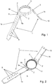
- the flexible bracelet 1 comprises a long strand 1a and a short strand 1b obtained in a flexible material, said long strand 1a comprising at its proximal end a transverse housing capable of receiving a fixing bar extending between a first pair of horns 2 of a watch case 3 and said short strand comprising at its proximal end a transverse housing capable of receiving a second fixing bar extending between a second pair of horns 2 of said watch case 3 and, at its distal end a second transverse housing adapted to receive the axis of a loop as will be detailed below.
- the proximal end of the long strand 1a ie the end of the long strand 1a intended to be secured to the watch case, comprises at its proximal end a transverse housing 4 capable of receiving a fixing bar and has a width less than 1 'wedge of said watch case 3.
- It furthermore comprises means capable of receiving respectively at least one so-called adapter element 5 in general U shape, obtained in a flexible material, the base 5a of which is capable of being joined to the strand 1a and whose arms 5b which extend parallel from the base 5a have at their free ends holes passing through 6 coaxial units capable of receiving the fixing bar, not shown in the figures, the distance separating the lateral edges of the arms 5b of the adapter 5 being substantially equal to the intersection of the watch case 3.
- Said coaxial holes 6 of the adapter 5 extend coaxially to the transverse housing of the 'proximal end of the short strand and the long strand respectively when the adapter is secured to said strand.
- the distance separating the inner edges of the arms 5b of the adapter 5 is substantially equal to the width of the proximal end of the strand 1a so that there is no space between said arms 5b and 1 proximal end of the strand 1a.
- the assembly has an aesthetic appearance strictly identical to the aesthetic appearance of a strand of a conventional watch strap.
- the distance between the inner edges of the arms 5b of the adapter 5 may be slightly less than the width of the proximal end of the strand 1a without departing from the scope of the invention.
- the proximal end of the long strand 1a has a transverse groove 7 extending on each of the faces of said strand and the base 5a of the adapter 5 comprises a through lumen 8, of rectangular cross section, emerging between the arms 5b so that the base 5a of the adapter 5 is received in said groove 7.
- the long strand 1a has holes 9 along its length in order to allow the bracelet to be closed by cooperating with a pin buckle or a folding clasp, not shown in the figures, secured to the distal end of the short strand 1b of the bracelet 1 .
- the adapter 5 corresponding to the measured spacing is chosen.
- the proximal end of the long strand 1a is then introduced into the lumen 8 of the base 5a of the adapter 5, the base 5a of the adapter slightly deforming, until said proximal end of the strand 1a projects between the arms 5b of the adapter.
- the base 5a of the adapter 5 then extends into the groove 7 and the transverse housing 4 of the proximal end of the strand 1a extends coaxially to the through holes 6 of the arms 5b of the adapter 5.
- a bar is then introduced into the through holes 8 and the transverse housing 4, then said bar is positioned between the horns of the watch case 3.
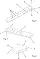
- the proximal end of the short strand 1b ie the end of the long strand 1a intended to be secured to the watch case, comprises at its proximal end a transverse housing 4 capable of receiving a fixing bar and has a width less than l 'entrecorne of said watch case 3 and the distal end of said short strand 1b, ie the free end opposite the proximal end, comprises a second transverse housing 10 adapted to receive the axis of a loop, such as a pin buckle or a folding clasp for example, not shown in the figures.
- It furthermore comprises means capable of receiving respectively at least one other element called an adapter 5 in the general shape of a U, obtained in a flexible material, the base 5a of which is capable of being secured to the strand 1a and the arms of which 5b which are extend parallel from the base 5a have at their free ends through holes 6 coaxial adapted to receive the fixing bar, not shown in the figures, the distance separating the lateral edges of the arms 5b of the adapter 5 being substantially equal to the between the watch case 3.
- Said coaxial holes 6 of the adapter 5 extend coaxially to the transverse housing of the proximal end of the short strand and respectively of the long strand when the adapter is secured to said strand.
- the distance separating the inner edges of the arms 5b of the adapter 5 is substantially equal to the width of the proximal end of the strand 1b so that there is no space between said arms 5b and 1 'proximal end of the strand 1a, thus providing an aesthetic appearance strictly identical to the aesthetic appearance of a strand of a conventional watch strap.
- the distance between the inner edges of the arms 5b of the adapter 5 may be slightly less than the width of the proximal end of the strand 1b without departing from the scope of the invention.
- the proximal end of the short strand 1b has a transverse groove 7 extending on each of the faces of said strand 1b and the base 5a of the adapter 5 comprises a through lumen 8, of rectangular cross section, opening out between the arms. 5b so that the base 5a of the adapter 5 is received in said groove 7.
- the positioning of the adapter 5 on the proximal end of the short strand 1b is done in the same way as for the long strand 1a previously described. It will be observed that the adapter can also be put in place at the proximal end of the long strand 1a and of the short strand 1b by introducing the distal end, and not the proximal end, of said long strand 1a and respectively short 1b, into the light 8 of the base 5a of the adapter without departing from the scope of the invention.
- the strap according to the invention preferably comprises a plurality of adapters 5, each adapter having a width at the level of its arms corresponding to a standard spacing of a watch case, such as a spacing of 18mm, 20mm, 22mm , 24mm, etc.
- the long strands 1a and short 1b, as well as the adapter 5 are obtained in a synthetic or natural plastic material, flexible, and elastic.
- said strands 1a and 1b and the adapter 5 are obtained in rubber or a thermoplastic elastomer called TPE or any other material well known to those skilled in the art.
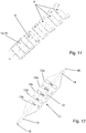
- a hand tool 11 consisting of a flat handle 12 comprising segments 12a, 12b, 12c, 12d, 12e substantially rectangular or trapezoidal of decreasing width from one end to the other of said handle 12.
- said handle 12 comprises 5 segments of different widths; however, it is obvious that the handle 12 may include any number of segments without as well go beyond the scope of the invention.
- At least one of the faces of each segment 12a, 12b, 12c, 12d, 12e of the handle 12 has an indication of the width of said segment 12a, 12b, 12c, 12d, 12e so that it suffices to position the handle 12 between the horns of the watch case until the lateral edges of one of the segments of the handle 12 bear on the inner edges of the horns of the watch case and then read the width indication corresponding to said segment to find the spacing ; once the entrecorne is known, it suffices to choose the adapter 5 described previously corresponding to this entrecorne.
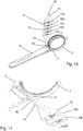
- the tool comprises two rods 13 and 14 respectively extending one end of said handle 12, the end of a first rod 13 comprising a U-shaped hook 15 and the end of the second rod 14 comprising a point 16, the point 16 or the hook 15 being used depending on the type of bar and horns of the watch case.
- said tool 11 comprises in the same manner as previously a flat handle 12 comprising segments 12a, 12b, 12c, 12d, 12e substantially rectangular or trapezoidal of decreasing width from one end to the other of said handle 12. At least one of faces of each segment 12a, 12b, 12c, 12d, 12th of the handle 12 includes an indication of the width of said segment 12a, 12b, 12c, 12d, 12e. Said tool 11 differs from that previously described by the fact that it comprises only a single rod 13 extending from one of the ends of the handle 12 and comprising a U-shaped hook 15.
- rod 13 may carry a point 16 in place of the hook 15 without departing from the scope of the invention.
Landscapes
- Physics & Mathematics (AREA)
- General Physics & Mathematics (AREA)
- Adornments (AREA)
Claims (9)
- Biegsames Armband (1), insbesondere für eine Uhr, das eine lange Bandseite (1a) und eine kurze Bandseite (1b) aus biegsamem Material umfasst, wobei die lange Bandseite (1a) an ihrem proximalen Ende eine quer verlaufende Aufnahme (4) umfasst, die einen, sich zwischen den Bandanstößen (2) eines Uhrgehäuses (3) erstreckenden Befestigungssteg aufnehmen kann, und die kurze Bandseite (1b) an ihrem proximalen Ende eine quer verlaufende Aufnahme (4) umfasst, die einen zweiten, sich zwischen den Bandanstößen (2) eines Uhrengehäuses (3) erstreckenden Befestigungssteg aufnehmen kann, und an ihrem distalen Ende eine zweite quer verlaufende Aufnahme (10), die die Achse einer Schließe aufnehmen kann, wobei die proximalen Enden der kurzen (1b) und der langen (1a) Bandseite eine Breite aufweisen, die kleiner als die Anstoßbreite des Uhrengehäuses (3) ist und Mittel umfassen, die jeweils mindestens ein sogenanntes, aus einem biegsamen Material hergestelltes Passstück (5) in genereller U-Form aufnehmen können, dessen Mittelteil (5a) an der Bandseite (1a, 1b) befestigt wird und dessen Ansätze (5b) an ihren freien Enden koaxiale Durchgangslöcher (6) zur Aufnahme des Befestigungsstegs aufweisen, wobei der Abstand zwischen den Seitenrändern der Ansätze (5b) des Passstücks (5) im Wesentlichen so groß ist, wie die Anstoßbreite des Uhrengehäuses (3), und sich die koaxialen Löcher (6) des Passstücks (5) koaxial zur quer verlaufenden Aufnahme (4) des proximalen Endes der kurzen Bandseite (1b) bzw. der langen Bandseite (1a) erstrecken, wenn das Passstück (5) mit der Bandseite (1a, 1b) fest verbunden ist, dadurch gekennzeichnet, dass das proximale Ende jeder Bandseite (1a, 1b) eine Quernut (7) umfasst, die sich zu beiden Seiten der jeweiligen Bandseite (1a, 1b) erstreckt, und dadurch, dass das Mittelteil (5a) des Passstücks (5) ein Durchgangsloch (8) umfasst, das zwischen den Ansätzen (5b) einmündet, so dass das Mittelteil (5a) des Passstücks in der Nut (7) aufgenommen wird.
- Biegsames Armband nach Anspruch 1, dadurch gekennzeichnet, dass der Abstand zwischen den Innenkanten der Ansätze (5b) des Passstücks (5) im Wesentlichen gleich der Breite des proximalen Endes der Bandseite (1a, 1b) ist.
- Biegsames Armband nach einem der Ansprüche 1 oder 2, dadurch gekennzeichnet, dass es eine Vielzahl von Passstücken (5) umfasst, wobei jedes Passstück (5) an seinen Ansätzen (5b) eine Breite aufweist, die so groß ist, wie die Standard-Anstoßbreite eines Uhrengehäuses (3).
- Biegsames Band nach einem der Ansprüche 1 bis 3, dadurch gekennzeichnet, dass die Bandseiten (1a, 1b) und das Passstück (5) aus einem synthetischen oder natürlichen, biegsamen, elastischen Kunststoff hergestellt sind.
- Biegsames Armband nach Anspruch 4, dadurch gekennzeichnet, dass die Bandseiten (1a, 1b) und das Passstück (5) aus Gummi oder einem thermoplastischen Elastomer, genannt TPE, hergestellt sind.
- Biegsames Armband nach einem der Ansprüche 1 bis 5, dadurch gekennzeichnet, dass die lange Bandseite (1a) über ihre Länge hinweg Löcher (9) umfasst und dass die Schließe der kurzen Bandseite (1b) aus einer Dorn- oder Faltschließe besteht.
- Handwerkzeug (11) zum Anbringen eines biegsamen Armbandes nach einem der Ansprüche 1 bis 6, dadurch gekennzeichnet, dass es aus mindestens einem flachen Griff (12) mit im Wesentlichen rechteckigen oder trapezförmigen Segmenten (12a, 12b, 12c, 12d, 12e) besteht, deren Breite von einem Ende zum anderen des besagten Griffs (12) abnimmt, und aus mindestens einem Stab (13, 14), der sich von einem Ende des besagten Griffs (12) ausgehend erstreckt, wobei das Ende des Stabs (13, 14) einen U-förmigen Haken (15) oder eine Spitze (16) aufweist.
- Werkzeug nach Anspruch 7, dadurch gekennzeichnet, dass mindestens eine der Seiten jedes Segments (12a, 12b, 12c, 12d, 12e) des Griffs (12) eine Angabe zur Breite des Segments (12a, 12b, 12c, 12d, 12e) umfasst.
- Werkzeug nach einem der Ansprüche 7 oder 8, dadurch gekennzeichnet, dass es an jedem Ende des Griffs (12) einen Stab (13, 14) umfasst, wobei ein erster Stab (14) an seinem Ende mit einer Spitze (16), und ein zweiter Stab (13) an seinem Ende mit einen U-förmigen Haken (15) bestückt ist.
Priority Applications (1)
| Application Number | Priority Date | Filing Date | Title |
|---|---|---|---|
| EP17162881.1A EP3379344B1 (de) | 2017-03-24 | 2017-03-24 | Flexibles armband mit anpassbarer breite |
Applications Claiming Priority (1)
| Application Number | Priority Date | Filing Date | Title |
|---|---|---|---|
| EP17162881.1A EP3379344B1 (de) | 2017-03-24 | 2017-03-24 | Flexibles armband mit anpassbarer breite |
Publications (2)
| Publication Number | Publication Date |
|---|---|
| EP3379344A1 EP3379344A1 (de) | 2018-09-26 |
| EP3379344B1 true EP3379344B1 (de) | 2020-04-22 |
Family
ID=58454866
Family Applications (1)
| Application Number | Title | Priority Date | Filing Date |
|---|---|---|---|
| EP17162881.1A Active EP3379344B1 (de) | 2017-03-24 | 2017-03-24 | Flexibles armband mit anpassbarer breite |
Country Status (1)
| Country | Link |
|---|---|
| EP (1) | EP3379344B1 (de) |
Family Cites Families (4)
| Publication number | Priority date | Publication date | Assignee | Title |
|---|---|---|---|---|
| US2677892A (en) * | 1953-02-17 | 1954-05-11 | Samuel Neiman | Measuring gauge for wrist watch case, strap, bracelet, and the like |
| NL8801648A (nl) | 1988-06-29 | 1990-01-16 | Rene Johannes Hubertus Corneli | Samenstel voor het bevestigen van banden aan polshorloges. |
| EP0871094A1 (de) * | 1997-04-08 | 1998-10-14 | Dexel S.A. | Mehrzweckwerkzeug, insbesondere für Uhrmacher |
| US20160004222A1 (en) * | 2014-07-03 | 2016-01-07 | Everest Horology Products | End links for use in coupling watch straps to bases of watches, and related methods |
-
2017
- 2017-03-24 EP EP17162881.1A patent/EP3379344B1/de active Active
Non-Patent Citations (1)
| Title |
|---|
| None * |
Also Published As
| Publication number | Publication date |
|---|---|
| EP3379344A1 (de) | 2018-09-26 |
Similar Documents
| Publication | Publication Date | Title |
|---|---|---|
| EP1790247B1 (de) | Einrichtung zum Verstellen der Länge eines Armbandes, Armband mit einer solchen Einrichtung, und Uhr ausgerüstet mit einem solchen Armband | |
| EP3470935B1 (de) | Einrastsystem, beispielsweise zum festmachen eines armbands an einer armbanduhr | |
| EP3560371B1 (de) | Vorrichtung zum befestigen eines armbands auf einem uhrengehäuse | |
| EP1646297B1 (de) | Bandförmiges verbindungsteil, insbesondere uhrarmband, das durch abschneiden gekürzt werden kann | |
| FR3021128A1 (fr) | Montre-bracelet a cornes et bracelet echangeables | |
| CH715584A1 (fr) | Embout arrangé pour être fixé de façon amovible à une barrette. | |
| EP1654950A1 (de) | Armbandverschluss | |
| EP0661938B1 (de) | Faltverschluss für armbänder | |
| EP3318156B1 (de) | Befestigungsvorrichtung | |
| EP3329796B1 (de) | Vorrichtung zur regulierung der bequemlichkeit der länge eines armbands | |
| EP3941300A1 (de) | Schnalle für ein uhrenband oder armband | |
| EP3454136B1 (de) | Armbanduhrengehäuse, armbanduhr und montagekit für eine armbanduhr, die dieses umfasst | |
| EP3698219B1 (de) | Vorrichtung zum befestigen eines armbands | |
| EP3379344A1 (de) | Flexibles armband mit anpassbarer breite | |
| FR3002726A1 (fr) | Moyen de liaison amovible entre deux elements d'un article de bijouterie ou d'un accessoire de mode | |
| CH704197A2 (fr) | Fermoir pour lien souple ou articulé tel que bracelet, bracelet de montre, ceinture. | |
| EP3669693B1 (de) | Verschluss und befestigungssystem | |
| CH719859A1 (fr) | Barrette à ressort pour bracelet de montre | |
| CH682290A5 (en) | Wrist watch bracelet - has holder between two sections of bracelet on opposite side to watch, designed to hold second instrument or container | |
| EP3886641B1 (de) | Uhr mit zwei armbandsträngen | |
| EP0174605A2 (de) | Einheit, am Handgelenk zu tragen | |
| EP1046354A1 (de) | Haarspange | |
| EP1351106B1 (de) | Schnappverbindungsvorrichtung | |
| EP4197388A1 (de) | Auswechselbares uhrenarmband | |
| CH718061A2 (fr) | Boucle démontable sans outils. |
Legal Events
| Date | Code | Title | Description |
|---|---|---|---|
| PUAI | Public reference made under article 153(3) epc to a published international application that has entered the european phase |
Free format text: ORIGINAL CODE: 0009012 |
|
| STAA | Information on the status of an ep patent application or granted ep patent |
Free format text: STATUS: THE APPLICATION HAS BEEN PUBLISHED |
|
| AK | Designated contracting states |
Kind code of ref document: A1 Designated state(s): AL AT BE BG CH CY CZ DE DK EE ES FI FR GB GR HR HU IE IS IT LI LT LU LV MC MK MT NL NO PL PT RO RS SE SI SK SM TR |
|
| AX | Request for extension of the european patent |
Extension state: BA ME |
|
| STAA | Information on the status of an ep patent application or granted ep patent |
Free format text: STATUS: REQUEST FOR EXAMINATION WAS MADE |
|
| 17P | Request for examination filed |
Effective date: 20190206 |
|
| RBV | Designated contracting states (corrected) |
Designated state(s): AL AT BE BG CH CY CZ DE DK EE ES FI FR GB GR HR HU IE IS IT LI LT LU LV MC MK MT NL NO PL PT RO RS SE SI SK SM TR |
|
| GRAJ | Information related to disapproval of communication of intention to grant by the applicant or resumption of examination proceedings by the epo deleted |
Free format text: ORIGINAL CODE: EPIDOSDIGR1 |
|
| STAA | Information on the status of an ep patent application or granted ep patent |
Free format text: STATUS: GRANT OF PATENT IS INTENDED |
|
| GRAP | Despatch of communication of intention to grant a patent |
Free format text: ORIGINAL CODE: EPIDOSNIGR1 |
|
| INTG | Intention to grant announced |
Effective date: 20191114 |
|
| RIN1 | Information on inventor provided before grant (corrected) |
Inventor name: BOURQUARD, PASCAL |
|
| GRAS | Grant fee paid |
Free format text: ORIGINAL CODE: EPIDOSNIGR3 |
|
| GRAA | (expected) grant |
Free format text: ORIGINAL CODE: 0009210 |
|
| STAA | Information on the status of an ep patent application or granted ep patent |
Free format text: STATUS: THE PATENT HAS BEEN GRANTED |
|
| AK | Designated contracting states |
Kind code of ref document: B1 Designated state(s): AL AT BE BG CH CY CZ DE DK EE ES FI FR GB GR HR HU IE IS IT LI LT LU LV MC MK MT NL NO PL PT RO RS SE SI SK SM TR |
|
| REG | Reference to a national code |
Ref country code: CH Ref legal event code: EP |
|
| REG | Reference to a national code |
Ref country code: IE Ref legal event code: FG4D Free format text: LANGUAGE OF EP DOCUMENT: FRENCH |
|
| REG | Reference to a national code |
Ref country code: DE Ref legal event code: R096 Ref document number: 602017015022 Country of ref document: DE |
|
| REG | Reference to a national code |
Ref country code: AT Ref legal event code: REF Ref document number: 1260941 Country of ref document: AT Kind code of ref document: T Effective date: 20200515 |
|
| REG | Reference to a national code |
Ref country code: CH Ref legal event code: NV Representative=s name: BOVARD SA NEUCHATEL CONSEILS EN PROPRIETE INTE, CH |
|
| REG | Reference to a national code |
Ref country code: LT Ref legal event code: MG4D |
|
| REG | Reference to a national code |
Ref country code: NL Ref legal event code: MP Effective date: 20200422 |
|
| PG25 | Lapsed in a contracting state [announced via postgrant information from national office to epo] |
Ref country code: NO Free format text: LAPSE BECAUSE OF FAILURE TO SUBMIT A TRANSLATION OF THE DESCRIPTION OR TO PAY THE FEE WITHIN THE PRESCRIBED TIME-LIMIT Effective date: 20200722 Ref country code: IS Free format text: LAPSE BECAUSE OF FAILURE TO SUBMIT A TRANSLATION OF THE DESCRIPTION OR TO PAY THE FEE WITHIN THE PRESCRIBED TIME-LIMIT Effective date: 20200822 Ref country code: GR Free format text: LAPSE BECAUSE OF FAILURE TO SUBMIT A TRANSLATION OF THE DESCRIPTION OR TO PAY THE FEE WITHIN THE PRESCRIBED TIME-LIMIT Effective date: 20200723 Ref country code: FI Free format text: LAPSE BECAUSE OF FAILURE TO SUBMIT A TRANSLATION OF THE DESCRIPTION OR TO PAY THE FEE WITHIN THE PRESCRIBED TIME-LIMIT Effective date: 20200422 Ref country code: SE Free format text: LAPSE BECAUSE OF FAILURE TO SUBMIT A TRANSLATION OF THE DESCRIPTION OR TO PAY THE FEE WITHIN THE PRESCRIBED TIME-LIMIT Effective date: 20200422 Ref country code: PT Free format text: LAPSE BECAUSE OF FAILURE TO SUBMIT A TRANSLATION OF THE DESCRIPTION OR TO PAY THE FEE WITHIN THE PRESCRIBED TIME-LIMIT Effective date: 20200824 Ref country code: NL Free format text: LAPSE BECAUSE OF FAILURE TO SUBMIT A TRANSLATION OF THE DESCRIPTION OR TO PAY THE FEE WITHIN THE PRESCRIBED TIME-LIMIT Effective date: 20200422 Ref country code: LT Free format text: LAPSE BECAUSE OF FAILURE TO SUBMIT A TRANSLATION OF THE DESCRIPTION OR TO PAY THE FEE WITHIN THE PRESCRIBED TIME-LIMIT Effective date: 20200422 |
|
| REG | Reference to a national code |
Ref country code: AT Ref legal event code: MK05 Ref document number: 1260941 Country of ref document: AT Kind code of ref document: T Effective date: 20200422 |
|
| PG25 | Lapsed in a contracting state [announced via postgrant information from national office to epo] |
Ref country code: HR Free format text: LAPSE BECAUSE OF FAILURE TO SUBMIT A TRANSLATION OF THE DESCRIPTION OR TO PAY THE FEE WITHIN THE PRESCRIBED TIME-LIMIT Effective date: 20200422 Ref country code: LV Free format text: LAPSE BECAUSE OF FAILURE TO SUBMIT A TRANSLATION OF THE DESCRIPTION OR TO PAY THE FEE WITHIN THE PRESCRIBED TIME-LIMIT Effective date: 20200422 Ref country code: BG Free format text: LAPSE BECAUSE OF FAILURE TO SUBMIT A TRANSLATION OF THE DESCRIPTION OR TO PAY THE FEE WITHIN THE PRESCRIBED TIME-LIMIT Effective date: 20200722 Ref country code: RS Free format text: LAPSE BECAUSE OF FAILURE TO SUBMIT A TRANSLATION OF THE DESCRIPTION OR TO PAY THE FEE WITHIN THE PRESCRIBED TIME-LIMIT Effective date: 20200422 |
|
| PG25 | Lapsed in a contracting state [announced via postgrant information from national office to epo] |
Ref country code: AL Free format text: LAPSE BECAUSE OF FAILURE TO SUBMIT A TRANSLATION OF THE DESCRIPTION OR TO PAY THE FEE WITHIN THE PRESCRIBED TIME-LIMIT Effective date: 20200422 |
|
| REG | Reference to a national code |
Ref country code: DE Ref legal event code: R097 Ref document number: 602017015022 Country of ref document: DE |
|
| PG25 | Lapsed in a contracting state [announced via postgrant information from national office to epo] |
Ref country code: ES Free format text: LAPSE BECAUSE OF FAILURE TO SUBMIT A TRANSLATION OF THE DESCRIPTION OR TO PAY THE FEE WITHIN THE PRESCRIBED TIME-LIMIT Effective date: 20200422 Ref country code: AT Free format text: LAPSE BECAUSE OF FAILURE TO SUBMIT A TRANSLATION OF THE DESCRIPTION OR TO PAY THE FEE WITHIN THE PRESCRIBED TIME-LIMIT Effective date: 20200422 Ref country code: SM Free format text: LAPSE BECAUSE OF FAILURE TO SUBMIT A TRANSLATION OF THE DESCRIPTION OR TO PAY THE FEE WITHIN THE PRESCRIBED TIME-LIMIT Effective date: 20200422 Ref country code: EE Free format text: LAPSE BECAUSE OF FAILURE TO SUBMIT A TRANSLATION OF THE DESCRIPTION OR TO PAY THE FEE WITHIN THE PRESCRIBED TIME-LIMIT Effective date: 20200422 Ref country code: DK Free format text: LAPSE BECAUSE OF FAILURE TO SUBMIT A TRANSLATION OF THE DESCRIPTION OR TO PAY THE FEE WITHIN THE PRESCRIBED TIME-LIMIT Effective date: 20200422 Ref country code: RO Free format text: LAPSE BECAUSE OF FAILURE TO SUBMIT A TRANSLATION OF THE DESCRIPTION OR TO PAY THE FEE WITHIN THE PRESCRIBED TIME-LIMIT Effective date: 20200422 Ref country code: CZ Free format text: LAPSE BECAUSE OF FAILURE TO SUBMIT A TRANSLATION OF THE DESCRIPTION OR TO PAY THE FEE WITHIN THE PRESCRIBED TIME-LIMIT Effective date: 20200422 |
|
| PG25 | Lapsed in a contracting state [announced via postgrant information from national office to epo] |
Ref country code: PL Free format text: LAPSE BECAUSE OF FAILURE TO SUBMIT A TRANSLATION OF THE DESCRIPTION OR TO PAY THE FEE WITHIN THE PRESCRIBED TIME-LIMIT Effective date: 20200422 Ref country code: SK Free format text: LAPSE BECAUSE OF FAILURE TO SUBMIT A TRANSLATION OF THE DESCRIPTION OR TO PAY THE FEE WITHIN THE PRESCRIBED TIME-LIMIT Effective date: 20200422 |
|
| PLBE | No opposition filed within time limit |
Free format text: ORIGINAL CODE: 0009261 |
|
| STAA | Information on the status of an ep patent application or granted ep patent |
Free format text: STATUS: NO OPPOSITION FILED WITHIN TIME LIMIT |
|
| 26N | No opposition filed |
Effective date: 20210125 |
|
| PG25 | Lapsed in a contracting state [announced via postgrant information from national office to epo] |
Ref country code: SI Free format text: LAPSE BECAUSE OF FAILURE TO SUBMIT A TRANSLATION OF THE DESCRIPTION OR TO PAY THE FEE WITHIN THE PRESCRIBED TIME-LIMIT Effective date: 20200422 |
|
| PG25 | Lapsed in a contracting state [announced via postgrant information from national office to epo] |
Ref country code: MC Free format text: LAPSE BECAUSE OF FAILURE TO SUBMIT A TRANSLATION OF THE DESCRIPTION OR TO PAY THE FEE WITHIN THE PRESCRIBED TIME-LIMIT Effective date: 20200422 |
|
| REG | Reference to a national code |
Ref country code: BE Ref legal event code: MM Effective date: 20210331 |
|
| PG25 | Lapsed in a contracting state [announced via postgrant information from national office to epo] |
Ref country code: IE Free format text: LAPSE BECAUSE OF NON-PAYMENT OF DUE FEES Effective date: 20210324 Ref country code: LU Free format text: LAPSE BECAUSE OF NON-PAYMENT OF DUE FEES Effective date: 20210324 |
|
| PG25 | Lapsed in a contracting state [announced via postgrant information from national office to epo] |
Ref country code: BE Free format text: LAPSE BECAUSE OF NON-PAYMENT OF DUE FEES Effective date: 20210331 |
|
| PGFP | Annual fee paid to national office [announced via postgrant information from national office to epo] |
Ref country code: GB Payment date: 20230330 Year of fee payment: 7 |
|
| PG25 | Lapsed in a contracting state [announced via postgrant information from national office to epo] |
Ref country code: CY Free format text: LAPSE BECAUSE OF FAILURE TO SUBMIT A TRANSLATION OF THE DESCRIPTION OR TO PAY THE FEE WITHIN THE PRESCRIBED TIME-LIMIT Effective date: 20200422 |
|
| P01 | Opt-out of the competence of the unified patent court (upc) registered |
Effective date: 20230527 |
|
| PG25 | Lapsed in a contracting state [announced via postgrant information from national office to epo] |
Ref country code: HU Free format text: LAPSE BECAUSE OF FAILURE TO SUBMIT A TRANSLATION OF THE DESCRIPTION OR TO PAY THE FEE WITHIN THE PRESCRIBED TIME-LIMIT; INVALID AB INITIO Effective date: 20170324 |
|
| PGFP | Annual fee paid to national office [announced via postgrant information from national office to epo] |
Ref country code: DE Payment date: 20230330 Year of fee payment: 7 |
|
| PG25 | Lapsed in a contracting state [announced via postgrant information from national office to epo] |
Ref country code: MK Free format text: LAPSE BECAUSE OF FAILURE TO SUBMIT A TRANSLATION OF THE DESCRIPTION OR TO PAY THE FEE WITHIN THE PRESCRIBED TIME-LIMIT Effective date: 20200422 |
|
| PG25 | Lapsed in a contracting state [announced via postgrant information from national office to epo] |
Ref country code: MT Free format text: LAPSE BECAUSE OF FAILURE TO SUBMIT A TRANSLATION OF THE DESCRIPTION OR TO PAY THE FEE WITHIN THE PRESCRIBED TIME-LIMIT Effective date: 20200422 |
|
| REG | Reference to a national code |
Ref country code: DE Ref legal event code: R119 Ref document number: 602017015022 Country of ref document: DE |
|
| GBPC | Gb: european patent ceased through non-payment of renewal fee |
Effective date: 20240324 |
|
| PG25 | Lapsed in a contracting state [announced via postgrant information from national office to epo] |
Ref country code: DE Free format text: LAPSE BECAUSE OF NON-PAYMENT OF DUE FEES Effective date: 20241001 |
|
| PG25 | Lapsed in a contracting state [announced via postgrant information from national office to epo] |
Ref country code: GB Free format text: LAPSE BECAUSE OF NON-PAYMENT OF DUE FEES Effective date: 20240324 |
|
| PG25 | Lapsed in a contracting state [announced via postgrant information from national office to epo] |
Ref country code: GB Free format text: LAPSE BECAUSE OF NON-PAYMENT OF DUE FEES Effective date: 20240324 Ref country code: DE Free format text: LAPSE BECAUSE OF NON-PAYMENT OF DUE FEES Effective date: 20241001 |
|
| PG25 | Lapsed in a contracting state [announced via postgrant information from national office to epo] |
Ref country code: TR Free format text: LAPSE BECAUSE OF FAILURE TO SUBMIT A TRANSLATION OF THE DESCRIPTION OR TO PAY THE FEE WITHIN THE PRESCRIBED TIME-LIMIT Effective date: 20200422 |
|
| REG | Reference to a national code |
Ref country code: CH Ref legal event code: R18 Free format text: ST27 STATUS EVENT CODE: U-0-0-R10-R18 (AS PROVIDED BY THE NATIONAL OFFICE) Effective date: 20260209 |
|
| REG | Reference to a national code |
Ref country code: CH Ref legal event code: R18 Free format text: ST27 STATUS EVENT CODE: U-0-0-R10-R18 (AS PROVIDED BY THE NATIONAL OFFICE) Effective date: 20260320 |
|
| REG | Reference to a national code |
Ref country code: CH Ref legal event code: U11 Free format text: ST27 STATUS EVENT CODE: U-0-0-U10-U11 (AS PROVIDED BY THE NATIONAL OFFICE) Effective date: 20260401 |
|
| PGFP | Annual fee paid to national office [announced via postgrant information from national office to epo] |
Ref country code: FR Payment date: 20260320 Year of fee payment: 10 |
|
| PGFP | Annual fee paid to national office [announced via postgrant information from national office to epo] |
Ref country code: IT Payment date: 20260330 Year of fee payment: 10 |
|
| PGFP | Annual fee paid to national office [announced via postgrant information from national office to epo] |
Ref country code: CH Payment date: 20260401 Year of fee payment: 10 |