EP3379344B1 - Bracelet souple a largeur adaptable - Google Patents
Bracelet souple a largeur adaptable Download PDFInfo
- Publication number
- EP3379344B1 EP3379344B1 EP17162881.1A EP17162881A EP3379344B1 EP 3379344 B1 EP3379344 B1 EP 3379344B1 EP 17162881 A EP17162881 A EP 17162881A EP 3379344 B1 EP3379344 B1 EP 3379344B1
- Authority
- EP
- European Patent Office
- Prior art keywords
- strand
- adapter
- proximal end
- watch case
- arms
- Prior art date
- Legal status (The legal status is an assumption and is not a legal conclusion. Google has not performed a legal analysis and makes no representation as to the accuracy of the status listed.)
- Active
Links
Images




Classifications
-
- A—HUMAN NECESSITIES
- A44—HABERDASHERY; JEWELLERY
- A44C—PERSONAL ADORNMENTS, e.g. JEWELLERY; COINS
- A44C5/00—Bracelets; Wrist-watch straps; Fastenings for bracelets or wrist-watch straps
- A44C5/14—Bracelets; Wrist-watch straps; Fastenings for bracelets or wrist-watch straps characterised by the way of fastening to a wrist-watch or the like
-
- G—PHYSICS
- G04—HOROLOGY
- G04B—MECHANICALLY-DRIVEN CLOCKS OR WATCHES; MECHANICAL PARTS OF CLOCKS OR WATCHES IN GENERAL; TIME PIECES USING THE POSITION OF THE SUN, MOON OR STARS
- G04B37/00—Cases
- G04B37/14—Suspending devices, supports or stands for time-pieces insofar as they form part of the case
- G04B37/1486—Arrangements for fixing to a bracelet
-
- G—PHYSICS
- G04—HOROLOGY
- G04D—APPARATUS OR TOOLS SPECIALLY DESIGNED FOR MAKING OR MAINTAINING CLOCKS OR WATCHES
- G04D3/00—Watchmakers' or watch-repairers' machines or tools for working materials
- G04D3/0002—Watchmakers' or watch-repairers' machines or tools for working materials for mechanical working other than with a lathe
- G04D3/0061—Watchmakers' or watch-repairers' machines or tools for working materials for mechanical working other than with a lathe for components for protecting the mechanism against external influences
- G04D3/0066—Watchmakers' or watch-repairers' machines or tools for working materials for mechanical working other than with a lathe for components for protecting the mechanism against external influences for the fastening means of the case or bracelet
Definitions
- the present invention relates to the field of flexible bracelets, in particular for the production of watch bracelets. It relates, more particularly, to a flexible bracelet, in particular for a watch, which comprises means for adapting the width of the bracelet to the wedge of the watch case and allowing the strap to be fixed whatever the wedge.
- the last operation consists in attaching the bracelet to the assembled watch comprising the case, the crystal, the movement, the case back, etc.
- the case includes a pair of protrusions called horns on two opposite sides of said case, between which the strands of the bracelet are secured by means of a spring axis called bar.
- Each bar generally consists of a small cylindrical metal tube in which extend pins loaded by a spring and able to cooperate with blind holes provided on the inner walls of the horns.
- a bar is inserted into a through housing provided at the proximal end of each strand, then the proximal end of each strand is positioned between the pairs of horns and it is made to penetrate the pins of the bars in the blind holes of the horns, possibly with the help of a hook-shaped tool.
- the distance between the horns varies from one watch case to another. Indeed, the different cases have 18mm, 20mm, 22mm, 24mm, etc. spacers. so it is necessary to use a strap of width adapted to that of the spacers.
- Said straps comprise a so-called metallic coupling part in the general shape of a T, the upper part of which has a transverse through hole for receiving a bar in order to snap the coupling part onto the bar of the watch case, said bar being positioned between the horns of the watch case, and the rod of which comprises a through hole capable of receiving an axis integral with the distal end of a strand of the bracelet.
- This type of coupling part nevertheless has the drawback of not being possible in a flexible material such as rubber or a thermoplastic elastomer.
- the strands of the strap tend to be offset from the watch case making wearing of the watch uncomfortable.
- the invention relates to a flexible bracelet, in particular for a watch, as defined in claim 1.
- the adapters make it possible to use a single width of strap strands for different spacers of the watch case while providing an aesthetic appearance of the strap identical to a conventional flexible watch strap. and while ensuring good positioning of the strands of the bracelet relative to the watch case.
- the distance separating the inner edges of the arms of the adapter is substantially equal to the width of the proximal end of the strand.
- each adapter has a width at the level of its arms corresponding to a standard spacing of a watch case.
- the strands and the adapter are obtained from a synthetic or natural plastic material, flexible and elastic.
- Said strands and the adapter are obtained in rubber or a thermoplastic elastomer called TPE.
- the long strand includes holes along its length and in that the loop of the short strand consists of a pin buckle or a folding clasp.
- Another object of the invention relates to a hand tool for fitting a flexible bracelet according to the invention, remarkable in that it consists of at least one flat handle comprising substantially rectangular or trapezoidal segments of decreasing width d 'one end to the other of said handle and of at least one rod extending from one of the ends of said handle, the end of the rod comprising a U-shaped hook or a point.
- At least one of the faces of each segment of the handle has an indication of the width of said segment.
- said tool comprises a rod at each end of said handle, a first rod carrying at its end a point and a second rod carrying at its end a U-shaped hook.
- the flexible bracelet 1 comprises a long strand 1a and a short strand 1b obtained in a flexible material, said long strand 1a comprising at its proximal end a transverse housing capable of receiving a fixing bar extending between a first pair of horns 2 of a watch case 3 and said short strand comprising at its proximal end a transverse housing capable of receiving a second fixing bar extending between a second pair of horns 2 of said watch case 3 and, at its distal end a second transverse housing adapted to receive the axis of a loop as will be detailed below.
- the proximal end of the long strand 1a ie the end of the long strand 1a intended to be secured to the watch case, comprises at its proximal end a transverse housing 4 capable of receiving a fixing bar and has a width less than 1 'wedge of said watch case 3.
- It furthermore comprises means capable of receiving respectively at least one so-called adapter element 5 in general U shape, obtained in a flexible material, the base 5a of which is capable of being joined to the strand 1a and whose arms 5b which extend parallel from the base 5a have at their free ends holes passing through 6 coaxial units capable of receiving the fixing bar, not shown in the figures, the distance separating the lateral edges of the arms 5b of the adapter 5 being substantially equal to the intersection of the watch case 3.
- Said coaxial holes 6 of the adapter 5 extend coaxially to the transverse housing of the 'proximal end of the short strand and the long strand respectively when the adapter is secured to said strand.
- the distance separating the inner edges of the arms 5b of the adapter 5 is substantially equal to the width of the proximal end of the strand 1a so that there is no space between said arms 5b and 1 proximal end of the strand 1a.
- the assembly has an aesthetic appearance strictly identical to the aesthetic appearance of a strand of a conventional watch strap.
- the distance between the inner edges of the arms 5b of the adapter 5 may be slightly less than the width of the proximal end of the strand 1a without departing from the scope of the invention.
- the proximal end of the long strand 1a has a transverse groove 7 extending on each of the faces of said strand and the base 5a of the adapter 5 comprises a through lumen 8, of rectangular cross section, emerging between the arms 5b so that the base 5a of the adapter 5 is received in said groove 7.
- the long strand 1a has holes 9 along its length in order to allow the bracelet to be closed by cooperating with a pin buckle or a folding clasp, not shown in the figures, secured to the distal end of the short strand 1b of the bracelet 1 .
- the adapter 5 corresponding to the measured spacing is chosen.
- the proximal end of the long strand 1a is then introduced into the lumen 8 of the base 5a of the adapter 5, the base 5a of the adapter slightly deforming, until said proximal end of the strand 1a projects between the arms 5b of the adapter.
- the base 5a of the adapter 5 then extends into the groove 7 and the transverse housing 4 of the proximal end of the strand 1a extends coaxially to the through holes 6 of the arms 5b of the adapter 5.
- a bar is then introduced into the through holes 8 and the transverse housing 4, then said bar is positioned between the horns of the watch case 3.
- the proximal end of the short strand 1b ie the end of the long strand 1a intended to be secured to the watch case, comprises at its proximal end a transverse housing 4 capable of receiving a fixing bar and has a width less than l 'entrecorne of said watch case 3 and the distal end of said short strand 1b, ie the free end opposite the proximal end, comprises a second transverse housing 10 adapted to receive the axis of a loop, such as a pin buckle or a folding clasp for example, not shown in the figures.
- It furthermore comprises means capable of receiving respectively at least one other element called an adapter 5 in the general shape of a U, obtained in a flexible material, the base 5a of which is capable of being secured to the strand 1a and the arms of which 5b which are extend parallel from the base 5a have at their free ends through holes 6 coaxial adapted to receive the fixing bar, not shown in the figures, the distance separating the lateral edges of the arms 5b of the adapter 5 being substantially equal to the between the watch case 3.
- Said coaxial holes 6 of the adapter 5 extend coaxially to the transverse housing of the proximal end of the short strand and respectively of the long strand when the adapter is secured to said strand.
- the distance separating the inner edges of the arms 5b of the adapter 5 is substantially equal to the width of the proximal end of the strand 1b so that there is no space between said arms 5b and 1 'proximal end of the strand 1a, thus providing an aesthetic appearance strictly identical to the aesthetic appearance of a strand of a conventional watch strap.
- the distance between the inner edges of the arms 5b of the adapter 5 may be slightly less than the width of the proximal end of the strand 1b without departing from the scope of the invention.
- the proximal end of the short strand 1b has a transverse groove 7 extending on each of the faces of said strand 1b and the base 5a of the adapter 5 comprises a through lumen 8, of rectangular cross section, opening out between the arms. 5b so that the base 5a of the adapter 5 is received in said groove 7.
- the positioning of the adapter 5 on the proximal end of the short strand 1b is done in the same way as for the long strand 1a previously described. It will be observed that the adapter can also be put in place at the proximal end of the long strand 1a and of the short strand 1b by introducing the distal end, and not the proximal end, of said long strand 1a and respectively short 1b, into the light 8 of the base 5a of the adapter without departing from the scope of the invention.
- the strap according to the invention preferably comprises a plurality of adapters 5, each adapter having a width at the level of its arms corresponding to a standard spacing of a watch case, such as a spacing of 18mm, 20mm, 22mm , 24mm, etc.
- the long strands 1a and short 1b, as well as the adapter 5 are obtained in a synthetic or natural plastic material, flexible, and elastic.
- said strands 1a and 1b and the adapter 5 are obtained in rubber or a thermoplastic elastomer called TPE or any other material well known to those skilled in the art.
- a hand tool 11 consisting of a flat handle 12 comprising segments 12a, 12b, 12c, 12d, 12e substantially rectangular or trapezoidal of decreasing width from one end to the other of said handle 12.
- said handle 12 comprises 5 segments of different widths; however, it is obvious that the handle 12 may include any number of segments without as well go beyond the scope of the invention.
- At least one of the faces of each segment 12a, 12b, 12c, 12d, 12e of the handle 12 has an indication of the width of said segment 12a, 12b, 12c, 12d, 12e so that it suffices to position the handle 12 between the horns of the watch case until the lateral edges of one of the segments of the handle 12 bear on the inner edges of the horns of the watch case and then read the width indication corresponding to said segment to find the spacing ; once the entrecorne is known, it suffices to choose the adapter 5 described previously corresponding to this entrecorne.
- the tool comprises two rods 13 and 14 respectively extending one end of said handle 12, the end of a first rod 13 comprising a U-shaped hook 15 and the end of the second rod 14 comprising a point 16, the point 16 or the hook 15 being used depending on the type of bar and horns of the watch case.
- said tool 11 comprises in the same manner as previously a flat handle 12 comprising segments 12a, 12b, 12c, 12d, 12e substantially rectangular or trapezoidal of decreasing width from one end to the other of said handle 12. At least one of faces of each segment 12a, 12b, 12c, 12d, 12th of the handle 12 includes an indication of the width of said segment 12a, 12b, 12c, 12d, 12e. Said tool 11 differs from that previously described by the fact that it comprises only a single rod 13 extending from one of the ends of the handle 12 and comprising a U-shaped hook 15.
- rod 13 may carry a point 16 in place of the hook 15 without departing from the scope of the invention.
Landscapes
- Physics & Mathematics (AREA)
- General Physics & Mathematics (AREA)
- Adornments (AREA)
Description
- La présente invention se rapporte au domaine des bracelets souples notamment pour la réalisation de bracelets montre. Elle concerne, plus particulièrement, un bracelet souple notamment pour montre qui comprend des moyens pour adapter la largeur du bracelet à l'entrecorne du boîtier de montre et permettre la fixation du bracelet quelle que soit l'entrecorne.
- Dans le domaine des montres-bracelets, il est bien connu des bracelets souples obtenus dans un matériau plastique synthétique ou naturel, flexible, et élastique, tel que du caoutchouc ou un élastomère thermoplastique dit TPE par exemple. Lors de la fabrication des montres-bracelets, la dernière opération consiste à attacher le bracelet à la montre assemblée comprenant le boîtier, la glace, le mouvement, le fond de boîtier, etc. Usuellement, le boîtier comporte une paires de protubérances appelées cornes sur deux côtés opposés dudit boîtier, entre lesquelles les brins du bracelet sont solidarisés au moyen d'un axe à ressort appelé barrette. Chaque barrette est généralement constituée d'un petit tube cylindrique métallique dans lequel s'étendent des tourillons chargés par un ressort et aptes à coopérer avec des trous borgnes prévus sur les parois intérieures des cornes.
- Ainsi, pour attacher les brins souples du bracelet à la montre, une barrette est introduite dans un logement traversant prévu à l'extrémité proximale de chaque brin, puis l'extrémité proximale de chaque brin est positionnée entre les paires de cornes et on fait pénétrer les tourillons des barrettes dans les trous borgnes des cornes, éventuellement avec l'aide d'un outil en forme de crochet.
- Toutefois, la distance entre les cornes, communément appelée entrecorne, varie d'un boitier de montre à l'autre. En effet, les différents boîtiers présentent des entrecornes de 18mm, 20mm, 22mm, 24mm, etc. de sorte qu'il est nécessaire d'utiliser un bracelet de largeur adaptée à celle des entrecornes.
- Ainsi, pour un possesseur de montres présentant des entrecornes différentes, il n'est pas possible de monter un même bracelet sur ces montres.
- Afin de remédier à cet inconvénient, on a déjà imaginé un bracelet de montre permettant de monter des brins d'une largeur quelconque sur un boîtier de montre dont l'entrecorne est quelconque.
- C'est le cas notamment de la demande de brevet néerlandais
NL8801648 - Ce type de pièce d'accouplement présente néanmoins l'inconvénient de ne pas être réalisable dans une matière souple tel que du caoutchouc ou un élastomère thermoplastique. De plus, compte tenu de la faible largeur de la tige de la pièce d'accouplement, les brins du bracelet ont tendance à se désaxer du boîtier de montre rendant le port de la montre inconfortable.
- On connait par ailleurs de la demande de brevet
US 2016/004222 A1 un bracelet de montre dans lequel les brins de bracelets sont liés aux cornes de la boite de montre par l'intermédiaire d'un insert de remplissage de largeur égale à l'entraxe des cornes. - On connaît par ailleurs de la demande de brevet
EP0871094 un outil à main pour la pose d'un bracelet. L'invention a pour but de surmonter, au moins partiellement, les inconvénients susmentionnés. - De façon plus précise, l'invention concerne un bracelet souple, notamment pour montre, tel que défini à la revendication 1.
- On comprend bien que, contrairement aux bracelets de l'art antérieur, les adaptateurs permettent d'utiliser une unique largeur de brins de bracelet pour différentes entrecornes de boîtier de montre tout en procurant un aspect esthétique du bracelet identique à un bracelet de montre souple classique et tout en assurant un bon positionnement des brins du bracelet par rapport au boîtier de montre.
- Par ailleurs, la distance séparant les bords intérieurs des bras de l'adaptateur est sensiblement égale à la largeur de l'extrémité proximale du brin.
- De préférence, il comporte une pluralité d'adaptateurs, chaque adaptateur présentant une largeur au niveau de ses bras correspondant à une entrecorne standard d'un boitier de montre.
- Par ailleurs, les brins et l'adaptateur sont obtenus dans un matériau plastique synthétique ou naturel, flexible, et élastique.
- Lesdits brins et l'adaptateur sont obtenus dans du caoutchouc ou un élastomère thermoplastique dit TPE.
- De préférence, le brin long comprend des trous sur sa longueur et en ce que la boucle du brin court consiste en une boucle ardillon ou une boucle déployante.
- Un autre objet de l'invention concerne un outil à main pour la pose d'un bracelet souple suivant l'invention remarquable en ce qu'il est constitué au moins d'un manche plat comportant des segments sensiblement rectangulaires ou trapézoïdaux de largeur décroissante d'une extrémité à l'autre dudit manche et d'au moins une tige s'étendant depuis l'une des extrémités dudit manche, l'extrémité de la tige comportant un crochet en forme de U ou une pointe.
- Au moins une des faces de chaque segment du manche comporte une indication de la largeur dudit segment.
- Selon une variante d'exécution, ledit outil comporte une tige à chacune des extrémités dudit manche, une première tige portant à son extrémité une pointe et une seconde tige portant à son extrémité un crochet en forme de U.
- D'autres avantages et caractéristiques ressortiront mieux de la description qui va suivre d'une unique variante d'exécution, donnée à titre d'exemple non limitatif, du bracelet souple conforme à l'invention, en référence aux dessins annexés sur lesquels:
- la
figure 1 est une vue en perspective de dessus du bracelet de montre conforme à l'invention monté sur un boîtier de montre, - la
figure 2 est une vue en perspective de dessous du bracelet de montre conforme à l'invention monté sur un boîtier de montre, - la
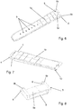
figure 3 est une vue en perspective du brin long du bracelet de montre conforme à l'invention, - la
figure 4 est une vue en perspective d'un élément dit adaptateur du brin long du bracelet de montre conforme à l'invention, - la
figure 5 est une vue en perspective de l'assemblage de l'adaptateur sur l'extrémité proximale du brin long du bracelet de montre conforme à l'invention, - la
figure 6 est une vue en perspective de l'adaptateur assemblé sur l'extrémité proximale du brin long du bracelet de montre conforme à l'invention, - la
figure 7 est une vue en perspective du brin court du bracelet de montre conforme à l'invention, - la
figure 8 est une vue en perspective d'un élément dit adaptateur du brin court du bracelet de montre conforme à l'invention, - la
figure 9 est une vue en perspective de l'adaptateur assemblé sur l'extrémité proximale du brin court du bracelet de montre conforme à l'invention, - la
figure 10 est une vue en coupe longitudinale du brin court du bracelet de montre muni de l'adaptateur suivant l'invention, - la
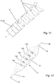
figure 11 est une vue en perspective d'un brin du bracelet de montre muni d'un adaptateur et de plusieurs adaptateur pour plusieurs entrecornes, suivant l'invention, - la
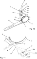
figure 12 est une vue en perspective d'un outil à main pour le montage d'un bracelet de montre suivant l'invention sur un boîtier de montre, - la
figure 13 est une vue en perspective de l'outil à main représenté sur lafigure 12 lors du montage du bracelet de montre sur un boîtier de montre, - la
figure 14 est une vue en perspective de l'outil à main lors du montage du bracelet de montre sur un autre boîtier de montre, - la
figure 15 est une vue en perspective d'une variante d'exécution de l'outil à main lors du montage du bracelet de montre sur un boîtier de montre, - la
figure 16 est une vue en perspective de l'outil à main représenté sur lafigure 15 lors du montage du bracelet de montre sur un boîtier de montre. - Dans la suite de la description suivant l'invention, les mêmes références numériques désignent les mêmes éléments. Les différentes vues ne sont pas nécessairement tracées à l'échelle.
- En référence aux
figures 1 et 2 , le bracelet souple 1 suivant l'invention comprend un brin long 1a et un brin court 1b obtenus dans une matière souple, ledit brin long 1a comprenant à son extrémité proximale un logement transversal apte à recevoir une barrette de fixation s'étendant entre une première paire de cornes 2 d'un boitier de montre 3 et ledit brin court comprenant à son extrémité proximale un logement transversal apte à recevoir une seconde barrette de fixation s'étendant entre une seconde paire de cornes 2 dudit boitier de montre 3 et, à son extrémité distale un second logement transversal apte à recevoir l'axe d'une boucle comme il sera détaillé plus loin. - En référence aux
figures 1 à 6 , l'extrémité proximale du brin long 1a, i.e. l'extrémité du brin long 1a destinée à être solidarisée au boîtier de montre, comprend à son extrémité proximale un logement transversal 4 apte à recevoir une barrette de fixation et présente une largeur inférieure à l'entrecorne dudit boîtier de montre 3. Elle comprend par ailleurs des moyens aptes à recevoir respectivement au moins un élément dit adaptateur 5 en forme générale de U, obtenu dans un matériau souple, dont la base 5a est apte à être solidarisée au brin 1a et dont les bras 5b qui s'étendent parallèlement depuis la base 5a comportent à leurs extrémités libres des trous traversant 6 coaxiaux aptes à recevoir la barrette de fixation, non représentée sur les figures, la distance séparant les bords latéraux des bras 5b de l'adaptateur 5 étant sensiblement égale à l'entrecorne du boîtier de montre 3. Lesdits trous coaxiaux 6 de l'adaptateur 5 s'étendent coaxialement au logement transversal de l'extrémité proximale du brin court et respectivement du brin long lorsque l'adaptateur est solidarisé audit brin. - De préférence, la distance séparant les bords intérieurs des bras 5b de l'adaptateur 5 est sensiblement égale à la largeur de l'extrémité proximale du brin 1a de sorte qu'il n'y ait pas d'espace entre lesdits bras 5b et l'extrémité proximale du brin 1a. Ainsi, lorsque l'adaptateur 5 est monté à l'extrémité libre du brin 1a, l'ensemble présente un aspect esthétique strictement identique à l'aspect esthétique d'un brin d'un bracelet de montre classique.
- Toutefois, il va de soi que la distance entre les bords intérieurs des bras 5b de l'adaptateur 5 pourra être légèrement inférieure à la largeur de l'extrémité proximale du brin 1a sans pour autant sortir du cadre de l'invention.
- De plus, l'extrémité proximale du brin long 1a comporte une gorge transversale 7 s'étendant sur chacune des faces dudit brin et la base 5a de l'adaptateur 5 comprend une lumière traversante 8, de section droite rectangulaire, débouchant entre les bras 5b de telle sorte que la base 5a de l'adaptateur 5 vienne se loger dans ladite gorge 7.
- Accessoirement, le brin long 1a comporte des trous 9 sur sa longueur afin de permettre la fermeture du bracelet en coopérant avec une boucle ardillon ou une boucle déployante, non représentée sur les figures, solidaire de l'extrémité distale du brin court 1b du bracelet 1.
- Il est bien évident que les trous 9 et la boucle ardillon ou déployante pourront être substitués par tout autre moyen de fermeture du bracelet bien connu de l'homme du métier sans pour autant sortir du cadre de l'invention.
- On expliquera maintenant la mise en place de l'adaptateur 5 sur l'extrémité proximale du brin long en référence aux
figures 1 à 6 . - Après avoir mesuré l'entrecorne du boîtier de montre 3 au moyen d'un outil adapté, qui sera détaillé plus loin, l'adaptateur 5 correspondant à l'entrecorne mesurée est choisi. On introduit alors l'extrémité proximale du brin long 1a dans la lumière 8 de la base 5a de l'adaptateur 5, la base 5a de l'adaptateur se déformant légèrement, jusqu'à ce que ladite extrémité proximale du brin 1a fasse saillie entre les bras 5b de l'adaptateur. La base 5a de l'adaptateur 5 s'étend alors dans la gorge 7 et le logement transversal 4 de l'extrémité proximale du brin 1a s'étend coaxialement aux trous traversant 6 des bras 5b de l'adaptateur 5. Une barrette, non représentée sur les figures, est alors introduite dans les trous traversant 8 et le logement transversal 4, puis ladite barrette est positionnée entre les cornes du boîtier de montre 3.
- En référence aux
figures 1 et 2 et7 à 10 , l'extrémité proximale du brin court 1b, i.e. l'extrémité du brin long 1a destinée à être solidarisée au boîtier de montre, comprend à son extrémité proximale un logement transversal 4 apte à recevoir une barrette de fixation et présente une largeur inférieure à l'entrecorne dudit boîtier de montre 3 et l'extrémité distale dudit brin court 1b, i.e. l'extrémité libre opposée à l'extrémité proximale, comprend un second logement transversal 10 apte à recevoir l'axe d'une boucle, telle qu'une boucle ardillon ou une boucle déployante par exemple, non représentée sur les figures. Elle comprend par ailleurs des moyens aptes à recevoir respectivement au moins un autre élément dit adaptateur 5 en forme générale de U, obtenu dans un matériau souple, dont la base 5a est apte à être solidarisée au brin 1a et dont les bras 5b qui s'étendent parallèlement depuis la base 5a comportent à leurs extrémités libres des trous traversant 6 coaxiaux aptes à recevoir la barrette de fixation, non représentée sur les figures, la distance séparant les bords latéraux des bras 5b de l'adaptateur 5 étant sensiblement égale à l'entrecorne du boîtier de montre 3. Lesdits trous coaxiaux 6 de l'adaptateur 5 s'étendent coaxialement au logement transversal de l'extrémité proximale du brin court et respectivement du brin long lorsque l'adaptateur est solidarisé audit brin. - De préférence, la distance séparant les bords intérieurs des bras 5b de l'adaptateur 5 est sensiblement égale à la largeur de l'extrémité proximale du brin 1b de sorte qu'il n'y ait pas d'espace entre lesdits bras 5b et l'extrémité proximale du brin 1a, procurant ainsi un aspect esthétique strictement identique à l'aspect esthétique d'un brin d'un bracelet de montre classique. Cependant, de la même manière que pour le brin long 1a la distance entre les bords intérieurs des bras 5b de l'adaptateur 5 pourra être légèrement inférieure à la largeur de l'extrémité proximale du brin 1b sans pour autant sortir du cadre de l'invention.
- De plus, l'extrémité proximale du brin court 1b comporte une gorge transversale 7 s'étendant sur chacune des faces dudit brin 1b et la base 5a de l'adaptateur 5 comprend une lumière traversante 8, de section droite rectangulaire, débouchant entre les bras 5b de telle sorte que la base 5a de l'adaptateur 5 vienne se loger dans ladite gorge 7.
- La mise en place de l'adaptateur 5 sur l'extrémité proximale du brin court 1b se fait de la même manière que pour le brin long 1a précédemment décrite. On observera que l'adaptateur pourra également être mis en place à l'extrémité proximale du brin long 1a et du brin court 1b en introduisant l'extrémité distale, et non l'extrémité proximale, dudit brin long 1a et respectivement court 1b, dans la lumière 8 de la base 5a de l'adaptateur sans sortir du cadre de l'invention.
- Par ailleurs, en référence à la
figure 11 , le bracelet suivant l'invention comporte de préférence une pluralité d'adaptateurs 5, chaque adaptateur présentant une largeur au niveau de ses bras correspondant à une entrecorne standard d'un boitier de montre, telle qu'une entrecorne de 18mm, 20mm, 22mm, 24mm, etc. - Par ailleurs, les brins long 1a et court 1b, ainsi que l'adaptateur 5 sont obtenus dans un matériau plastique synthétique ou naturel, flexible, et élastique. Par exemple, lesdits brins 1a et 1b et l'adaptateur 5 sont obtenus dans du caoutchouc ou un élastomère thermoplastique dit TPE ou tout autre matériau bien connu de l'homme du métier.
- Afin de faciliter la pose du bracelet souple suivant l'invention sur un boîtier de montre, en référence aux
figures 12 à 14 , il est prévu un outil à main 11 constitué d'un manche plat 12 comportant des segments 12a,12b,12c,12d,12e sensiblement rectangulaires ou trapézoïdaux de largeur décroissante d'une extrémité à l'autre dudit manche 12. Dans cet exemple particulier de réalisation, ledit manche 12 comporte 5 segments de largeurs différentes ; toutefois, il est bien évident que le manche 12 pourra comprendre un nombre quelconque de segments sans pour autant sortir du cadre de l'invention. Au moins une des faces de chaque segment 12a,12b,12c,12d,12e du manche 12 comporte une indication de la largeur dudit segment 12a,12b,12c,12d,12e de sorte qu'il suffit de positionner le manche 12 entre les cornes du boîtier de montre jusqu'à ce que les bords latéraux de l'un des segments du manche 12 prennent appui sur les bords intérieurs des cornes du boîtier de montre puis de lire l'indication de largeur correspondant audit segment pour connaître l'entrecorne ; une fois l'entrecorne connue, il suffit de choisir l'adaptateur 5 décrit précédemment correspondant à cette entrecorne. Par ailleurs l'outil comporte deux tiges 13 et 14 s'étendant respectivement l'une des extrémités dudit manche 12, l'extrémité d'une première tige 13 comportant un crochet en forme de U 15 et l'extrémité de la seconde tige 14 comportant une pointe 16, la pointe 16 ou le crochet 15 étant utilisés en fonction du type de barrette et de cornes du boîtier de montre. - Selon une variante d'exécution, en référence aux
figures 15 et 16 , ledit outil 11 comporte de la même manière que précédemment un manche plat 12 comportant des segments 12a,12b,12c,12d,12e sensiblement rectangulaires ou trapézoïdaux de largeur décroissante d'une extrémité à l'autre dudit manche 12. Au moins une des faces de chaque segment 12a,12b,12c,12d,12e du manche 12 comporte une indication de la largeur dudit segment 12a,12b,12c,12d,12e. Ledit outil 11 se distingue de celui précédemment décrit par le fait qu'il ne comporte qu'une seule tige 13 s'étendant depuis l'une des extrémités du manche 12 et comportant un crochet en forme de U 15. - Il est bien évident que la tige 13 pourra porter une pointe 16 en lieu et place du crochet 15 sans pour autant sortir du cadre de l'invention.
- Enfin, il est bien évident que les exemples que l'on vient de donner ne sont que des illustrations particulières et en aucun cas limitatifs quant au domaine d'application de l'invention.
Claims (9)
- Bracelet souple (1), notamment pour montre, comprenant un brin long (1a) et un brin court (1b) obtenus dans une matière souple, ledit brin long (1a) comprenant à son extrémité proximale un logement transversal (4) apte à recevoir une barrette de fixation s'étendant entre les cornes (2) d'un boitier de montre (3), et ledit brin court (1b) comprenant à son extrémité proximale un logement transversal (4) apte à recevoir une seconde barrette de fixation s'étendant entre les cornes (2) d'un boitier de montre (3) et, à son extrémité distale un second logement transversal (10) apte à recevoir l'axe d'une boucle, les extrémités proximales des brins court (1b) et long (1a) présentant une largeur inférieure à l'entrecorne du boîtier de montre (3) et comprennent des moyens aptes à recevoir respectivement au moins un élément dit adaptateur (5) en forme générale de U, obtenu dans un matériau souple, dont la base (5a) est apte à être solidarisée au brin (1a, 1b) et dont les bras (5b) comportent à leurs extrémités libres des trous traversant coaxiaux (6) aptes à recevoir la barrette de fixation, la distance séparant les bords latéraux des bras (5b) de l'adaptateur (5) étant sensiblement égale à l'entrecorne du boîtier de montre (3), et lesdits trous coaxiaux (6) de l'adaptateur (5) s'étendant coaxialement au logement transversal (4) de l'extrémité proximale du brin court (1b) et respectivement du brin long (1a) lorsque l'adaptateur (5) est solidarisé audit brin (1a,1b), caractérisé en ce que l'extrémité proximale de chaque brin (1a,1b) comporte une gorge transversale (7) s'étendant sur chacune des faces dudit brin (1a, 1b) et en ce que la base (5a) de l'adaptateur (5) comprend une lumière traversante (8) débouchant entre les bras (5b) de telle sorte que la base (5a) de l'adaptateur vienne se loger dans ladite gorge (7).
- Bracelet souple selon la revendication 1 caractérisé en ce que la distance séparant les bords intérieurs des bras (5b) de l'adaptateur (5) est sensiblement égale à la largeur de l'extrémité proximale du brin (1a, 1b).
- Bracelet souple selon l'une quelconque des revendications 1 ou 2 caractérisé en ce qu'il comporte une pluralité d'adaptateurs (5), chaque adaptateur (5) présentant une largeur au niveau de ses bras (5b) correspondant à une entrecorne standard d'un boitier de montre (3).
- Bracelet souple selon l'une quelconque des revendications 1 à 3 caractérisé en ce que les brins (1a,1b) et l'adaptateur (5) sont obtenus dans un matériau plastique synthétique ou naturel, flexible, et élastique.
- Bracelet souple selon la revendication 4 caractérisé en ce que les brins (1a, 1b) et l'adaptateur (5) sont obtenus dans du caoutchouc ou un élastomère thermoplastique dit TPE.
- Bracelet souple selon l'une quelconque des revendications 1 à 5 caractérisé en ce que le brin long (1a) comprend des trous (9) sur sa longueur et en ce que la boucle du brin court (1b) consiste en une boucle ardillon ou une boucle déployante.
- Outil à main (11) pour la pose d'un bracelet souple suivant l'une quelconque des revendications 1 à 6 caractérisé en ce qu'il est constitué au moins d'un manche plat (12) comportant des segments (12a,12b,12c,12d,12e) sensiblement rectangulaires ou trapézoïdaux de largeur décroissante d'une extrémité à l'autre dudit manche (12) et d'au moins une tige (13,14) s'étendant depuis l'une des extrémités dudit manche (12), l'extrémité de la tige (13,14) comportant un crochet en forme de U (15) ou une pointe (16).
- Outil selon la revendication 7 caractérisé en ce qu'au moins une des faces de chaque segment (12a,12b,12c,12d,12e) du manche (12) comporte une indication de la largeur dudit segment (12a, 12b, 12c, 12d, 12e).
- Outil selon l'une quelconque des revendications 7 ou 8 caractérisé en ce qu'il comporte une tige (13,14) à chacune des extrémités dudit manche (12), une première tige (14) portant à son extrémité une pointe (16) et une seconde tige (13) portant à son extrémité un crochet en forme de U (15).
Priority Applications (1)
| Application Number | Priority Date | Filing Date | Title |
|---|---|---|---|
| EP17162881.1A EP3379344B1 (fr) | 2017-03-24 | 2017-03-24 | Bracelet souple a largeur adaptable |
Applications Claiming Priority (1)
| Application Number | Priority Date | Filing Date | Title |
|---|---|---|---|
| EP17162881.1A EP3379344B1 (fr) | 2017-03-24 | 2017-03-24 | Bracelet souple a largeur adaptable |
Publications (2)
| Publication Number | Publication Date |
|---|---|
| EP3379344A1 EP3379344A1 (fr) | 2018-09-26 |
| EP3379344B1 true EP3379344B1 (fr) | 2020-04-22 |
Family
ID=58454866
Family Applications (1)
| Application Number | Title | Priority Date | Filing Date |
|---|---|---|---|
| EP17162881.1A Active EP3379344B1 (fr) | 2017-03-24 | 2017-03-24 | Bracelet souple a largeur adaptable |
Country Status (1)
| Country | Link |
|---|---|
| EP (1) | EP3379344B1 (fr) |
Family Cites Families (4)
| Publication number | Priority date | Publication date | Assignee | Title |
|---|---|---|---|---|
| US2677892A (en) * | 1953-02-17 | 1954-05-11 | Samuel Neiman | Measuring gauge for wrist watch case, strap, bracelet, and the like |
| NL8801648A (nl) | 1988-06-29 | 1990-01-16 | Rene Johannes Hubertus Corneli | Samenstel voor het bevestigen van banden aan polshorloges. |
| EP0871094A1 (fr) * | 1997-04-08 | 1998-10-14 | Dexel S.A. | Outil multifonctions, en particulier pour horloger |
| US20160004222A1 (en) * | 2014-07-03 | 2016-01-07 | Everest Horology Products | End links for use in coupling watch straps to bases of watches, and related methods |
-
2017
- 2017-03-24 EP EP17162881.1A patent/EP3379344B1/fr active Active
Non-Patent Citations (1)
| Title |
|---|
| None * |
Also Published As
| Publication number | Publication date |
|---|---|
| EP3379344A1 (fr) | 2018-09-26 |
Similar Documents
| Publication | Publication Date | Title |
|---|---|---|
| EP1790247B1 (fr) | Dispositif de réglage de la longueur d'un bracelet, bracelet muni d'un tel dispositif, et montre équipée d'un tel bracelet | |
| EP3470935B1 (fr) | Système de clipsage par exemple pour attacher un bracelet à une montre | |
| EP3560371B1 (fr) | Dispositif de fixation d'un bracelet sur une boîte de montre | |
| EP1646297B1 (fr) | Lien en forme de bande, notamment bracelet de montre, pouvant etre raccourci par decoupage | |
| FR3021128A1 (fr) | Montre-bracelet a cornes et bracelet echangeables | |
| CH715584A1 (fr) | Embout arrangé pour être fixé de façon amovible à une barrette. | |
| EP1654950A1 (fr) | Fermoir de bracelet | |
| EP0661938B1 (fr) | Fermoir du type a boucle deployante pour bracelet | |
| EP3318156B1 (fr) | Dispositif d'attache | |
| EP3329796B1 (fr) | Dispositif de reglage de confort de la longueur d'un bracelet | |
| EP3454136B1 (fr) | Boite de montre, montre-bracelet et kit d'assemblage d'une montre-bracelet la comprenant | |
| EP3698219B1 (fr) | Dispositif de fixation d'un bracelet | |
| WO2020187907A1 (fr) | Fermoir pour bracelet | |
| EP3379344A1 (fr) | Bracelet souple a largeur adaptable | |
| FR3002726A1 (fr) | Moyen de liaison amovible entre deux elements d'un article de bijouterie ou d'un accessoire de mode | |
| CH704197A2 (fr) | Fermoir pour lien souple ou articulé tel que bracelet, bracelet de montre, ceinture. | |
| EP3669693B1 (fr) | Fermoir et systeme d'attache | |
| CH719859A1 (fr) | Barrette à ressort pour bracelet de montre | |
| CH682290A5 (en) | Wrist watch bracelet - has holder between two sections of bracelet on opposite side to watch, designed to hold second instrument or container | |
| EP3886641B1 (fr) | Montre comprenant deux brins de bracelet | |
| EP0174605A2 (fr) | Ensemble destiné à être porté au poignet | |
| EP1046354A1 (fr) | Pince, notamment pince à cheveux | |
| EP1351106B1 (fr) | Dispositif d'encliquetage | |
| EP4197388A1 (fr) | Bracelet de montre interchangeable | |
| CH718061A2 (fr) | Boucle démontable sans outils. |
Legal Events
| Date | Code | Title | Description |
|---|---|---|---|
| PUAI | Public reference made under article 153(3) epc to a published international application that has entered the european phase |
Free format text: ORIGINAL CODE: 0009012 |
|
| STAA | Information on the status of an ep patent application or granted ep patent |
Free format text: STATUS: THE APPLICATION HAS BEEN PUBLISHED |
|
| AK | Designated contracting states |
Kind code of ref document: A1 Designated state(s): AL AT BE BG CH CY CZ DE DK EE ES FI FR GB GR HR HU IE IS IT LI LT LU LV MC MK MT NL NO PL PT RO RS SE SI SK SM TR |
|
| AX | Request for extension of the european patent |
Extension state: BA ME |
|
| STAA | Information on the status of an ep patent application or granted ep patent |
Free format text: STATUS: REQUEST FOR EXAMINATION WAS MADE |
|
| 17P | Request for examination filed |
Effective date: 20190206 |
|
| RBV | Designated contracting states (corrected) |
Designated state(s): AL AT BE BG CH CY CZ DE DK EE ES FI FR GB GR HR HU IE IS IT LI LT LU LV MC MK MT NL NO PL PT RO RS SE SI SK SM TR |
|
| GRAJ | Information related to disapproval of communication of intention to grant by the applicant or resumption of examination proceedings by the epo deleted |
Free format text: ORIGINAL CODE: EPIDOSDIGR1 |
|
| STAA | Information on the status of an ep patent application or granted ep patent |
Free format text: STATUS: GRANT OF PATENT IS INTENDED |
|
| GRAP | Despatch of communication of intention to grant a patent |
Free format text: ORIGINAL CODE: EPIDOSNIGR1 |
|
| INTG | Intention to grant announced |
Effective date: 20191114 |
|
| RIN1 | Information on inventor provided before grant (corrected) |
Inventor name: BOURQUARD, PASCAL |
|
| GRAS | Grant fee paid |
Free format text: ORIGINAL CODE: EPIDOSNIGR3 |
|
| GRAA | (expected) grant |
Free format text: ORIGINAL CODE: 0009210 |
|
| STAA | Information on the status of an ep patent application or granted ep patent |
Free format text: STATUS: THE PATENT HAS BEEN GRANTED |
|
| AK | Designated contracting states |
Kind code of ref document: B1 Designated state(s): AL AT BE BG CH CY CZ DE DK EE ES FI FR GB GR HR HU IE IS IT LI LT LU LV MC MK MT NL NO PL PT RO RS SE SI SK SM TR |
|
| REG | Reference to a national code |
Ref country code: CH Ref legal event code: EP |
|
| REG | Reference to a national code |
Ref country code: IE Ref legal event code: FG4D Free format text: LANGUAGE OF EP DOCUMENT: FRENCH |
|
| REG | Reference to a national code |
Ref country code: DE Ref legal event code: R096 Ref document number: 602017015022 Country of ref document: DE |
|
| REG | Reference to a national code |
Ref country code: AT Ref legal event code: REF Ref document number: 1260941 Country of ref document: AT Kind code of ref document: T Effective date: 20200515 |
|
| REG | Reference to a national code |
Ref country code: CH Ref legal event code: NV Representative=s name: BOVARD SA NEUCHATEL CONSEILS EN PROPRIETE INTE, CH |
|
| REG | Reference to a national code |
Ref country code: LT Ref legal event code: MG4D |
|
| REG | Reference to a national code |
Ref country code: NL Ref legal event code: MP Effective date: 20200422 |
|
| PG25 | Lapsed in a contracting state [announced via postgrant information from national office to epo] |
Ref country code: NO Free format text: LAPSE BECAUSE OF FAILURE TO SUBMIT A TRANSLATION OF THE DESCRIPTION OR TO PAY THE FEE WITHIN THE PRESCRIBED TIME-LIMIT Effective date: 20200722 Ref country code: IS Free format text: LAPSE BECAUSE OF FAILURE TO SUBMIT A TRANSLATION OF THE DESCRIPTION OR TO PAY THE FEE WITHIN THE PRESCRIBED TIME-LIMIT Effective date: 20200822 Ref country code: GR Free format text: LAPSE BECAUSE OF FAILURE TO SUBMIT A TRANSLATION OF THE DESCRIPTION OR TO PAY THE FEE WITHIN THE PRESCRIBED TIME-LIMIT Effective date: 20200723 Ref country code: FI Free format text: LAPSE BECAUSE OF FAILURE TO SUBMIT A TRANSLATION OF THE DESCRIPTION OR TO PAY THE FEE WITHIN THE PRESCRIBED TIME-LIMIT Effective date: 20200422 Ref country code: SE Free format text: LAPSE BECAUSE OF FAILURE TO SUBMIT A TRANSLATION OF THE DESCRIPTION OR TO PAY THE FEE WITHIN THE PRESCRIBED TIME-LIMIT Effective date: 20200422 Ref country code: PT Free format text: LAPSE BECAUSE OF FAILURE TO SUBMIT A TRANSLATION OF THE DESCRIPTION OR TO PAY THE FEE WITHIN THE PRESCRIBED TIME-LIMIT Effective date: 20200824 Ref country code: NL Free format text: LAPSE BECAUSE OF FAILURE TO SUBMIT A TRANSLATION OF THE DESCRIPTION OR TO PAY THE FEE WITHIN THE PRESCRIBED TIME-LIMIT Effective date: 20200422 Ref country code: LT Free format text: LAPSE BECAUSE OF FAILURE TO SUBMIT A TRANSLATION OF THE DESCRIPTION OR TO PAY THE FEE WITHIN THE PRESCRIBED TIME-LIMIT Effective date: 20200422 |
|
| REG | Reference to a national code |
Ref country code: AT Ref legal event code: MK05 Ref document number: 1260941 Country of ref document: AT Kind code of ref document: T Effective date: 20200422 |
|
| PG25 | Lapsed in a contracting state [announced via postgrant information from national office to epo] |
Ref country code: HR Free format text: LAPSE BECAUSE OF FAILURE TO SUBMIT A TRANSLATION OF THE DESCRIPTION OR TO PAY THE FEE WITHIN THE PRESCRIBED TIME-LIMIT Effective date: 20200422 Ref country code: LV Free format text: LAPSE BECAUSE OF FAILURE TO SUBMIT A TRANSLATION OF THE DESCRIPTION OR TO PAY THE FEE WITHIN THE PRESCRIBED TIME-LIMIT Effective date: 20200422 Ref country code: BG Free format text: LAPSE BECAUSE OF FAILURE TO SUBMIT A TRANSLATION OF THE DESCRIPTION OR TO PAY THE FEE WITHIN THE PRESCRIBED TIME-LIMIT Effective date: 20200722 Ref country code: RS Free format text: LAPSE BECAUSE OF FAILURE TO SUBMIT A TRANSLATION OF THE DESCRIPTION OR TO PAY THE FEE WITHIN THE PRESCRIBED TIME-LIMIT Effective date: 20200422 |
|
| PG25 | Lapsed in a contracting state [announced via postgrant information from national office to epo] |
Ref country code: AL Free format text: LAPSE BECAUSE OF FAILURE TO SUBMIT A TRANSLATION OF THE DESCRIPTION OR TO PAY THE FEE WITHIN THE PRESCRIBED TIME-LIMIT Effective date: 20200422 |
|
| REG | Reference to a national code |
Ref country code: DE Ref legal event code: R097 Ref document number: 602017015022 Country of ref document: DE |
|
| PG25 | Lapsed in a contracting state [announced via postgrant information from national office to epo] |
Ref country code: ES Free format text: LAPSE BECAUSE OF FAILURE TO SUBMIT A TRANSLATION OF THE DESCRIPTION OR TO PAY THE FEE WITHIN THE PRESCRIBED TIME-LIMIT Effective date: 20200422 Ref country code: AT Free format text: LAPSE BECAUSE OF FAILURE TO SUBMIT A TRANSLATION OF THE DESCRIPTION OR TO PAY THE FEE WITHIN THE PRESCRIBED TIME-LIMIT Effective date: 20200422 Ref country code: SM Free format text: LAPSE BECAUSE OF FAILURE TO SUBMIT A TRANSLATION OF THE DESCRIPTION OR TO PAY THE FEE WITHIN THE PRESCRIBED TIME-LIMIT Effective date: 20200422 Ref country code: EE Free format text: LAPSE BECAUSE OF FAILURE TO SUBMIT A TRANSLATION OF THE DESCRIPTION OR TO PAY THE FEE WITHIN THE PRESCRIBED TIME-LIMIT Effective date: 20200422 Ref country code: DK Free format text: LAPSE BECAUSE OF FAILURE TO SUBMIT A TRANSLATION OF THE DESCRIPTION OR TO PAY THE FEE WITHIN THE PRESCRIBED TIME-LIMIT Effective date: 20200422 Ref country code: RO Free format text: LAPSE BECAUSE OF FAILURE TO SUBMIT A TRANSLATION OF THE DESCRIPTION OR TO PAY THE FEE WITHIN THE PRESCRIBED TIME-LIMIT Effective date: 20200422 Ref country code: CZ Free format text: LAPSE BECAUSE OF FAILURE TO SUBMIT A TRANSLATION OF THE DESCRIPTION OR TO PAY THE FEE WITHIN THE PRESCRIBED TIME-LIMIT Effective date: 20200422 |
|
| PG25 | Lapsed in a contracting state [announced via postgrant information from national office to epo] |
Ref country code: PL Free format text: LAPSE BECAUSE OF FAILURE TO SUBMIT A TRANSLATION OF THE DESCRIPTION OR TO PAY THE FEE WITHIN THE PRESCRIBED TIME-LIMIT Effective date: 20200422 Ref country code: SK Free format text: LAPSE BECAUSE OF FAILURE TO SUBMIT A TRANSLATION OF THE DESCRIPTION OR TO PAY THE FEE WITHIN THE PRESCRIBED TIME-LIMIT Effective date: 20200422 |
|
| PLBE | No opposition filed within time limit |
Free format text: ORIGINAL CODE: 0009261 |
|
| STAA | Information on the status of an ep patent application or granted ep patent |
Free format text: STATUS: NO OPPOSITION FILED WITHIN TIME LIMIT |
|
| 26N | No opposition filed |
Effective date: 20210125 |
|
| PG25 | Lapsed in a contracting state [announced via postgrant information from national office to epo] |
Ref country code: SI Free format text: LAPSE BECAUSE OF FAILURE TO SUBMIT A TRANSLATION OF THE DESCRIPTION OR TO PAY THE FEE WITHIN THE PRESCRIBED TIME-LIMIT Effective date: 20200422 |
|
| PG25 | Lapsed in a contracting state [announced via postgrant information from national office to epo] |
Ref country code: MC Free format text: LAPSE BECAUSE OF FAILURE TO SUBMIT A TRANSLATION OF THE DESCRIPTION OR TO PAY THE FEE WITHIN THE PRESCRIBED TIME-LIMIT Effective date: 20200422 |
|
| REG | Reference to a national code |
Ref country code: BE Ref legal event code: MM Effective date: 20210331 |
|
| PG25 | Lapsed in a contracting state [announced via postgrant information from national office to epo] |
Ref country code: IE Free format text: LAPSE BECAUSE OF NON-PAYMENT OF DUE FEES Effective date: 20210324 Ref country code: LU Free format text: LAPSE BECAUSE OF NON-PAYMENT OF DUE FEES Effective date: 20210324 |
|
| PG25 | Lapsed in a contracting state [announced via postgrant information from national office to epo] |
Ref country code: BE Free format text: LAPSE BECAUSE OF NON-PAYMENT OF DUE FEES Effective date: 20210331 |
|
| PGFP | Annual fee paid to national office [announced via postgrant information from national office to epo] |
Ref country code: GB Payment date: 20230330 Year of fee payment: 7 |
|
| PG25 | Lapsed in a contracting state [announced via postgrant information from national office to epo] |
Ref country code: CY Free format text: LAPSE BECAUSE OF FAILURE TO SUBMIT A TRANSLATION OF THE DESCRIPTION OR TO PAY THE FEE WITHIN THE PRESCRIBED TIME-LIMIT Effective date: 20200422 |
|
| P01 | Opt-out of the competence of the unified patent court (upc) registered |
Effective date: 20230527 |
|
| PG25 | Lapsed in a contracting state [announced via postgrant information from national office to epo] |
Ref country code: HU Free format text: LAPSE BECAUSE OF FAILURE TO SUBMIT A TRANSLATION OF THE DESCRIPTION OR TO PAY THE FEE WITHIN THE PRESCRIBED TIME-LIMIT; INVALID AB INITIO Effective date: 20170324 |
|
| PGFP | Annual fee paid to national office [announced via postgrant information from national office to epo] |
Ref country code: DE Payment date: 20230330 Year of fee payment: 7 |
|
| PG25 | Lapsed in a contracting state [announced via postgrant information from national office to epo] |
Ref country code: MK Free format text: LAPSE BECAUSE OF FAILURE TO SUBMIT A TRANSLATION OF THE DESCRIPTION OR TO PAY THE FEE WITHIN THE PRESCRIBED TIME-LIMIT Effective date: 20200422 |
|
| PG25 | Lapsed in a contracting state [announced via postgrant information from national office to epo] |
Ref country code: MT Free format text: LAPSE BECAUSE OF FAILURE TO SUBMIT A TRANSLATION OF THE DESCRIPTION OR TO PAY THE FEE WITHIN THE PRESCRIBED TIME-LIMIT Effective date: 20200422 |
|
| REG | Reference to a national code |
Ref country code: DE Ref legal event code: R119 Ref document number: 602017015022 Country of ref document: DE |
|
| GBPC | Gb: european patent ceased through non-payment of renewal fee |
Effective date: 20240324 |
|
| PG25 | Lapsed in a contracting state [announced via postgrant information from national office to epo] |
Ref country code: DE Free format text: LAPSE BECAUSE OF NON-PAYMENT OF DUE FEES Effective date: 20241001 |
|
| PG25 | Lapsed in a contracting state [announced via postgrant information from national office to epo] |
Ref country code: GB Free format text: LAPSE BECAUSE OF NON-PAYMENT OF DUE FEES Effective date: 20240324 |
|
| PG25 | Lapsed in a contracting state [announced via postgrant information from national office to epo] |
Ref country code: GB Free format text: LAPSE BECAUSE OF NON-PAYMENT OF DUE FEES Effective date: 20240324 Ref country code: DE Free format text: LAPSE BECAUSE OF NON-PAYMENT OF DUE FEES Effective date: 20241001 |
|
| PGFP | Annual fee paid to national office [announced via postgrant information from national office to epo] |
Ref country code: IT Payment date: 20250319 Year of fee payment: 9 |
|
| PGFP | Annual fee paid to national office [announced via postgrant information from national office to epo] |
Ref country code: CH Payment date: 20250401 Year of fee payment: 9 |
|
| PG25 | Lapsed in a contracting state [announced via postgrant information from national office to epo] |
Ref country code: TR Free format text: LAPSE BECAUSE OF FAILURE TO SUBMIT A TRANSLATION OF THE DESCRIPTION OR TO PAY THE FEE WITHIN THE PRESCRIBED TIME-LIMIT Effective date: 20200422 |
|
| REG | Reference to a national code |
Ref country code: CH Ref legal event code: R18 Free format text: ST27 STATUS EVENT CODE: U-0-0-R10-R18 (AS PROVIDED BY THE NATIONAL OFFICE) Effective date: 20260209 |
|
| REG | Reference to a national code |
Ref country code: CH Ref legal event code: R18 Free format text: ST27 STATUS EVENT CODE: U-0-0-R10-R18 (AS PROVIDED BY THE NATIONAL OFFICE) Effective date: 20260320 |
|
| REG | Reference to a national code |
Ref country code: CH Ref legal event code: U11 Free format text: ST27 STATUS EVENT CODE: U-0-0-U10-U11 (AS PROVIDED BY THE NATIONAL OFFICE) Effective date: 20260401 |
|
| PGFP | Annual fee paid to national office [announced via postgrant information from national office to epo] |
Ref country code: FR Payment date: 20260320 Year of fee payment: 10 |