EP3379719B1 - Procédé destinés à transferer une unité de transport à une position de transmission - Google Patents
Procédé destinés à transferer une unité de transport à une position de transmission Download PDFInfo
- Publication number
- EP3379719B1 EP3379719B1 EP18172313.1A EP18172313A EP3379719B1 EP 3379719 B1 EP3379719 B1 EP 3379719B1 EP 18172313 A EP18172313 A EP 18172313A EP 3379719 B1 EP3379719 B1 EP 3379719B1
- Authority
- EP
- European Patent Office
- Prior art keywords
- transport unit
- transport
- force
- transfer position
- sides
- Prior art date
- Legal status (The legal status is an assumption and is not a legal conclusion. Google has not performed a legal analysis and makes no representation as to the accuracy of the status listed.)
- Active
Links
Images


Classifications
-
- H—ELECTRICITY
- H02—GENERATION; CONVERSION OR DISTRIBUTION OF ELECTRIC POWER
- H02K—DYNAMO-ELECTRIC MACHINES
- H02K41/00—Propulsion systems in which a rigid body is moved along a path due to dynamo-electric interaction between the body and a magnetic field travelling along the path
- H02K41/02—Linear motors; Sectional motors
-
- H—ELECTRICITY
- H02—GENERATION; CONVERSION OR DISTRIBUTION OF ELECTRIC POWER
- H02P—CONTROL OR REGULATION OF ELECTRIC MOTORS, ELECTRIC GENERATORS OR DYNAMO-ELECTRIC CONVERTERS; CONTROLLING TRANSFORMERS, REACTORS OR CHOKE COILS
- H02P6/00—Arrangements for controlling synchronous motors or other dynamo-electric motors using electronic commutation dependent on the rotor position; Electronic commutators therefor
- H02P6/006—Controlling linear motors
-
- B—PERFORMING OPERATIONS; TRANSPORTING
- B60—VEHICLES IN GENERAL
- B60L—PROPULSION OF ELECTRICALLY-PROPELLED VEHICLES; SUPPLYING ELECTRIC POWER FOR AUXILIARY EQUIPMENT OF ELECTRICALLY-PROPELLED VEHICLES; ELECTRODYNAMIC BRAKE SYSTEMS FOR VEHICLES IN GENERAL; MAGNETIC SUSPENSION OR LEVITATION FOR VEHICLES; MONITORING OPERATING VARIABLES OF ELECTRICALLY-PROPELLED VEHICLES; ELECTRIC SAFETY DEVICES FOR ELECTRICALLY-PROPELLED VEHICLES
- B60L13/00—Electric propulsion for monorail vehicles, suspension vehicles or rack railways; Magnetic suspension or levitation for vehicles
- B60L13/003—Crossings; Points
-
- B—PERFORMING OPERATIONS; TRANSPORTING
- B60—VEHICLES IN GENERAL
- B60L—PROPULSION OF ELECTRICALLY-PROPELLED VEHICLES; SUPPLYING ELECTRIC POWER FOR AUXILIARY EQUIPMENT OF ELECTRICALLY-PROPELLED VEHICLES; ELECTRODYNAMIC BRAKE SYSTEMS FOR VEHICLES IN GENERAL; MAGNETIC SUSPENSION OR LEVITATION FOR VEHICLES; MONITORING OPERATING VARIABLES OF ELECTRICALLY-PROPELLED VEHICLES; ELECTRIC SAFETY DEVICES FOR ELECTRICALLY-PROPELLED VEHICLES
- B60L13/00—Electric propulsion for monorail vehicles, suspension vehicles or rack railways; Magnetic suspension or levitation for vehicles
- B60L13/03—Electric propulsion by linear motors
-
- B—PERFORMING OPERATIONS; TRANSPORTING
- B65—CONVEYING; PACKING; STORING; HANDLING THIN OR FILAMENTARY MATERIAL
- B65G—TRANSPORT OR STORAGE DEVICES, e.g. CONVEYORS FOR LOADING OR TIPPING, SHOP CONVEYOR SYSTEMS OR PNEUMATIC TUBE CONVEYORS
- B65G54/00—Non-mechanical conveyors not otherwise provided for
- B65G54/02—Non-mechanical conveyors not otherwise provided for electrostatic, electric, or magnetic
-
- H—ELECTRICITY
- H02—GENERATION; CONVERSION OR DISTRIBUTION OF ELECTRIC POWER
- H02K—DYNAMO-ELECTRIC MACHINES
- H02K41/00—Propulsion systems in which a rigid body is moved along a path due to dynamo-electric interaction between the body and a magnetic field travelling along the path
-
- H—ELECTRICITY
- H02—GENERATION; CONVERSION OR DISTRIBUTION OF ELECTRIC POWER
- H02K—DYNAMO-ELECTRIC MACHINES
- H02K41/00—Propulsion systems in which a rigid body is moved along a path due to dynamo-electric interaction between the body and a magnetic field travelling along the path
- H02K41/02—Linear motors; Sectional motors
- H02K41/03—Synchronous motors; Motors moving step by step; Reluctance motors
-
- H—ELECTRICITY
- H02—GENERATION; CONVERSION OR DISTRIBUTION OF ELECTRIC POWER
- H02P—CONTROL OR REGULATION OF ELECTRIC MOTORS, ELECTRIC GENERATORS OR DYNAMO-ELECTRIC CONVERTERS; CONTROLLING TRANSFORMERS, REACTORS OR CHOKE COILS
- H02P21/00—Arrangements or methods for the control of electric machines by vector control, e.g. by control of field orientation
- H02P21/06—Rotor flux based control involving the use of rotor position or rotor speed sensors
-
- H—ELECTRICITY
- H02—GENERATION; CONVERSION OR DISTRIBUTION OF ELECTRIC POWER
- H02P—CONTROL OR REGULATION OF ELECTRIC MOTORS, ELECTRIC GENERATORS OR DYNAMO-ELECTRIC CONVERTERS; CONTROLLING TRANSFORMERS, REACTORS OR CHOKE COILS
- H02P21/00—Arrangements or methods for the control of electric machines by vector control, e.g. by control of field orientation
- H02P21/12—Stator flux based control involving the use of rotor position or rotor speed sensors
-
- H—ELECTRICITY
- H02—GENERATION; CONVERSION OR DISTRIBUTION OF ELECTRIC POWER
- H02P—CONTROL OR REGULATION OF ELECTRIC MOTORS, ELECTRIC GENERATORS OR DYNAMO-ELECTRIC CONVERTERS; CONTROLLING TRANSFORMERS, REACTORS OR CHOKE COILS
- H02P25/00—Arrangements or methods for the control of AC motors characterised by the kind of AC motor or by structural details
- H02P25/02—Arrangements or methods for the control of AC motors characterised by the kind of AC motor or by structural details characterised by the kind of motor
- H02P25/06—Linear motors
- H02P25/062—Linear motors of the induction type
-
- H—ELECTRICITY
- H02—GENERATION; CONVERSION OR DISTRIBUTION OF ELECTRIC POWER
- H02P—CONTROL OR REGULATION OF ELECTRIC MOTORS, ELECTRIC GENERATORS OR DYNAMO-ELECTRIC CONVERTERS; CONTROLLING TRANSFORMERS, REACTORS OR CHOKE COILS
- H02P25/00—Arrangements or methods for the control of AC motors characterised by the kind of AC motor or by structural details
- H02P25/02—Arrangements or methods for the control of AC motors characterised by the kind of AC motor or by structural details characterised by the kind of motor
- H02P25/06—Linear motors
- H02P25/064—Linear motors of the synchronous type
-
- E—FIXED CONSTRUCTIONS
- E01—CONSTRUCTION OF ROADS, RAILWAYS, OR BRIDGES
- E01B—PERMANENT WAY; PERMANENT-WAY TOOLS; MACHINES FOR MAKING RAILWAYS OF ALL KINDS
- E01B25/00—Tracks for special kinds of railways
- E01B25/08—Tracks for mono-rails with centre of gravity of vehicle above the load-bearing rail
- E01B25/12—Switches; Crossings
-
- E—FIXED CONSTRUCTIONS
- E01—CONSTRUCTION OF ROADS, RAILWAYS, OR BRIDGES
- E01B—PERMANENT WAY; PERMANENT-WAY TOOLS; MACHINES FOR MAKING RAILWAYS OF ALL KINDS
- E01B25/00—Tracks for special kinds of railways
- E01B25/30—Tracks for magnetic suspension or levitation vehicles
- E01B25/34—Switches; Frogs; Crossings
-
- H—ELECTRICITY
- H02—GENERATION; CONVERSION OR DISTRIBUTION OF ELECTRIC POWER
- H02K—DYNAMO-ELECTRIC MACHINES
- H02K41/00—Propulsion systems in which a rigid body is moved along a path due to dynamo-electric interaction between the body and a magnetic field travelling along the path
- H02K41/02—Linear motors; Sectional motors
- H02K41/03—Synchronous motors; Motors moving step by step; Reluctance motors
- H02K41/031—Synchronous motors; Motors moving step by step; Reluctance motors of the permanent magnet type
-
- Y—GENERAL TAGGING OF NEW TECHNOLOGICAL DEVELOPMENTS; GENERAL TAGGING OF CROSS-SECTIONAL TECHNOLOGIES SPANNING OVER SEVERAL SECTIONS OF THE IPC; TECHNICAL SUBJECTS COVERED BY FORMER USPC CROSS-REFERENCE ART COLLECTIONS [XRACs] AND DIGESTS
- Y02—TECHNOLOGIES OR APPLICATIONS FOR MITIGATION OR ADAPTATION AGAINST CLIMATE CHANGE
- Y02P—CLIMATE CHANGE MITIGATION TECHNOLOGIES IN THE PRODUCTION OR PROCESSING OF GOODS
- Y02P70/00—Climate change mitigation technologies in the production process for final industrial or consumer products
- Y02P70/10—Greenhouse gas [GHG] capture, material saving, heat recovery or other energy efficient measures, e.g. motor control, characterised by manufacturing processes, e.g. for rolling metal or metal working
-
- Y—GENERAL TAGGING OF NEW TECHNOLOGICAL DEVELOPMENTS; GENERAL TAGGING OF CROSS-SECTIONAL TECHNOLOGIES SPANNING OVER SEVERAL SECTIONS OF THE IPC; TECHNICAL SUBJECTS COVERED BY FORMER USPC CROSS-REFERENCE ART COLLECTIONS [XRACs] AND DIGESTS
- Y02—TECHNOLOGIES OR APPLICATIONS FOR MITIGATION OR ADAPTATION AGAINST CLIMATE CHANGE
- Y02T—CLIMATE CHANGE MITIGATION TECHNOLOGIES RELATED TO TRANSPORTATION
- Y02T10/00—Road transport of goods or passengers
- Y02T10/60—Other road transportation technologies with climate change mitigation effect
- Y02T10/64—Electric machine technologies in electromobility
Definitions
- the present invention relates to a method for transferring a transport unit of a long stator linear motor at a transfer position from a first transport section, with a number of drive coils arranged one behind the other in the direction of movement of the transport unit on a guide structure in the area of the transfer position, to a second transport section, with a number of drive coils in the direction of movement drive coils arranged one behind the other on a guide structure of the transport unit in the area of the transfer position, with excitation magnets being arranged on both sides of the transport unit, which interact with drive coils in the area of the transport unit, with drive coils being provided in the area of the transfer position on both sides of the transport unit, which are provided with the excitation magnets can cooperate on the two sides of the transport unit, and the second transport section on one side with an exit from the transfer position Drive coils on only one side, which can interact with excitation magnets on this side of the transport unit, and where, due to the interaction of the excitation magnets with ferromagnetic components of the guide structure on both
- a multiplicity of electric drive coils which form the stator, are arranged along a transport path.
- a number of excitation magnets either as permanent magnets or as electrical coils or short-circuit windings, which interact with the drive coils, are arranged on a transport unit.
- the long stator linear motor can be used as a synchronous machine, both self-excited or externally excited, or be designed as an asynchronous machine.
- By controlling the individual drive coils to regulate the magnetic flux a propulsive force is generated and the transport unit can be moved along the transport route. It is also possible to arrange a large number of transport units along the transport route, the movements of which can be controlled individually and independently of one another.
- a long stator linear motor is characterized in particular by better and more flexible utilization over the entire working range of the movement (speed, acceleration), individual regulation / control of the transport units along the transport route, improved energy utilization, the reduction of maintenance costs due to the lower number of wear parts, a simple exchange of the transport units, efficient monitoring and error detection and an optimization of the product flow.
- Examples of such long stator linear motors can be WO 2013/143783 A1 , the US 6,876,107 B2 , the US 2013/0074724 A1 or the WO 2004/103792 A1 can be removed.
- the drive coils of the stator are arranged on the top of the transport path.
- the permanent magnets are arranged on the underside of the transport units.
- the permanent magnets are provided on both sides of the centrally arranged drive coils, so that the permanent magnets surround the stator of the long stator linear motor and the drive coils interact with the permanent magnets arranged on both sides.
- the transport units are guided along the transport route either by means of guide rollers, for example in the WO 2013/143783 A1 or the US 6,876,107 B2 , or by magnetic guidance, such as in the WO 2004/103792 A1 .
- guide magnets are provided on both sides of the transport units, which interact with guide rods arranged opposite on the transport path.
- the guide rods form a magnetic yoke that close the magnetic circuit of the guide magnets.
- the magnetic guide circles thus formed thus counteract a lateral movement of the transport units, with which the transport units are guided laterally.
- the U.S. 6,101,952 A can be removed.
- transfer positions for example in the form of switches, are necessary in order to enable complex and intelligent path planning or path realizations of the transport facility.
- these transfer positions were often implemented with the help of additional mechanical release units.
- An example of this can be found in the US 2013/0074724 A1 in the form of a mechanically triggered switch by means of movable deflection arms or a turntable.
- auxiliary coils are used in order to trigger a switch.
- the auxiliary coils are arranged, for example, on the magnetic yoke of the magnetic guide circuit, while the auxiliary coils in the US 2013/0074724 A1 are arranged laterally on the transport path.
- a magnetic flux is impressed into the magnetic guide circuit by the auxiliary coils, which generates a lateral force that directs the transport unit in one direction.
- the additional auxiliary coils required increase the effort involved in implementing a transport device, since the auxiliary coils must also be installed and electrically supplied and controlled.
- separate guide magnets are required on the transport units.
- the WO 2015/036302 A1 and the WO 2015/042409 A1 describes magnetically activated turnouts of a long-stator linear motor that do not require additional auxiliary coils.
- the excitation magnets of the transport units are arranged between drive coils arranged on both sides.
- a side force can be generated by energizing the drive coils on only one side of the transport path, with which the transport unit can be steered in the region of the switch in order to move the transport unit further on the desired transport path after the switch.
- the switch is triggered in such a way that the drive coils in the area of the switch are only activated on the side of the transport path along which the transport unit is to move on.
- the drive coils on the other side are deactivated ( DE 1 963 505 A1 , WO 2015/036302 A1 , WO 2015/042409 A1 ) or reversed polarity ( WO 2015/036302 A1 ). But that brings with it certain problems. If the drive coils on one side in the area of the switch are deactivated, the transport unit in the area of the switch loses half of the propulsive force, so that the area of the switch can only be driven through at a reduced speed.
- the transport units could jam, which would be unfavorable for the control of the transport device.
- the polarity reversal is purely static and a specific, predetermined side force can be activated or deactivated. By reversing the polarity, a specific, predetermined lateral force can thus be set in the area of the switch become. If the lateral force is overdimensioned for reasons of safety when operating the points, this leads to increased friction and increased wear.
- the transport units would therefore have to be appropriately dimensioned mechanically, which makes the transport units larger, heavier and more expensive. Apart from this, the wear on the mechanical components of the transport units, in particular the mechanical guide elements, also increases.
- the lateral force is selected to be smaller, the safety of the switch movement is reduced, for example if the transport unit with a load is heavier than assumed. Reversing the polarity to trigger the switch is therefore also rather disadvantageous for the operation of a long-stator linear motor.
- this object is achieved according to the invention by a method according to claim 1, this solution comprising that a stator current is impressed in a transfer area of the transfer position on at least one side of the transport unit in at least one drive coil, which generates an electromagnetic side force on the transport unit and that the on Side forces resulting from both sides of the transport unit, in each case as the sum of the active excitation magnetic side force and the electromagnetic side force, differ in amount in order to generate a steering effect, the steering effect guiding the transport unit in the transfer position along the second transport section.
- No additional auxiliary elements (such as coils, switches, etc.) are required for steering the transport units in the transfer position.
- the triggering occurs purely by the drive coils required for the propulsion movement and is based on a regulation of the electromagnetic field.
- a steering effect can thus be generated in a simple manner by impressing a force component that creates a lateral force on at least one side of the transport unit.
- the propulsion force acting on the transport unit is regulated with a propulsion force component of the stator current and the steering effect is regulated in the transfer position with a side force component of the stator current
- the regulation of the propulsion force and the regulation of the propulsion force can advantageously be decoupled.
- the propulsion force can be regulated with a position regulator by correcting a position error to regulate the position of the transport unit
- the steering effect can be regulated with a steering regulator by correcting a flow error.
- a transport device 1 in the form of a long stator linear motor is shown by way of example.
- the transport device 1 consists of a number of transport sections A1... A9, which are combined to form the transport device 1.
- This modular structure enables a very flexible design of the transport device 1, but also requires a large number of transfer positions U1 ... U9 at which the transport units T1 ... Tn moved on the transport device 1 (for reasons of clarity are shown in FIG Fig. 1 not all transport units marked with a reference symbol) are transferred from one transport section A1 ... A9 to another.
- the transport device 1 is designed as a long stator linear motor, in which the transport sections A1 ... A9 each form a part of a long stator of a long stator linear motor in a manner known per se.
- a large number of electrical drive coils are therefore arranged in a known manner along the transport sections A1 ... A9 in the longitudinal direction (in Fig. 1 not shown for reasons of clarity), which are connected to the transport units T1 ... Tn with excitation magnets (see Fig. 3 ) work together.
- a propulsive force F v is generated, which the transport units T1 ...
- Each of the transport units T1 ... Tn can be moved individually (speed, acceleration, path) and independently (apart from avoiding possible collisions) of the other transport units T1 ... Tn. Since this basic principle of a long-stator linear motor is sufficiently known, it will not be discussed in more detail here.
- a transport unit T1... Tn which is located in a transport segment TS, is therefore controlled by the associated segment control unit 11.
- This essentially means that the segment control unit 11 controls the drive coils 7, 8 of the associated transport segment TS in such a way that the transport unit T1 ... Tn is moved along the transport segment TS in the desired manner (speed, acceleration) by the propulsive force. If a transport unit T1 ...
- Tn moves from one transport segment TSn to the next transport segment TSn + 1, the control of the transport unit T1 ... Tn is also transferred in an orderly manner to the segment control unit 11 n + 1 of the next transport segment TSn + 1.
- the movement of the transport unit T1... Tn through the transport device 1 is monitored in a superordinate system control unit 10, which is connected to the segment control units 11.
- the system control unit 10 controls the movement of the transport units Tn through the transport device 1, for example by means of position specifications.
- the segment control units 11 then regulate a possible error between the target value and the actual value.
- Some transfer positions U1 ... U10 are also arranged along the transport route of the transport device 1. Different types of transfer positions U1 ... U10 are conceivable here. For example, a switch is provided at the transfer positions U2 and U7, while the other transfer positions U1, U3 ... U6, U8, U9 are designed, for example, as change points from one transport section A1 ... A8 to another. At the transfer position U10, for example, a transition from a one-sided transport section A2 to a two-sided transport section A9 is provided. At the transfer position U2 (switch), a transport unit T6 can, for example, be moved on the transport section A2 or the transport section A3. At a transfer position U1 (change position), a transport unit T5 is transferred from the one-sided transport section A1 to the one-sided transport section A2.
- a number of work stations S1 ... S4 can also be arranged along the transport route of the transport device 1, which is essentially given by the longitudinal direction of the transport sections A1 ... A8, in which manipulation of the transport units T1 ... Tn transported components takes place.
- the work station S1 can be designed, for example, as an inward and / or outward transfer station in which finished components are removed and components to be processed are transferred to a transport unit T1... Tn. Any processing steps can be carried out on the components in the workstations S2 ... S4.
- the transport units T1 ... Tn can be stopped for processing in a work station S1 ... S4, e.g. in a filling station in which empty bottles are filled, or moved through, e.g. in a temperature control station in which components are temperature treated, possibly also at a different speed than between the workstations S1 ... S4.
- FIG Fig. 2 Another example of a transport device 1 is shown in FIG Fig. 2 shown.
- Five self-contained transport sections A1 ... A5 are provided here.
- the transport sections A2 ... A4 are used here for the introduction of various components at the work stations S1 ... S3.
- a work station S4 of a transport section A5 these components are connected to one another or processed in some other way and discharged from the transport device 1.
- Another transport section A1 is used to transfer the components from the transport sections A2, A3, A4 to the transport section A5.
- transfer positions U1, U2, U3 are provided in order to transfer the transport units Tn with the various components to the transport section A1.
- a transfer position U4 is provided in which the transport units Tn with the various components are transferred to the transport section A5.
- FIG. 3 shows a cross section through any transport section Am and a transport unit Tn moving thereon.
- a transport unit Tn here consists of a base body 2 and a component holder 3 arranged on it, wherein the component holder 3 can in principle be arranged at any point on the base body 2, in particular also on the bottom for hanging components.
- the number of excitation magnets 4, 5 of the long stator linear motor is arranged on the base body 2 on both sides of the transport unit Tn.
- the transport path of the transport device 1, or a transport section Am, or a transport segment TSm of a transport section Am, is formed by a stationary guide structure 6 on which the drive coils 7, 8 of the long stator linear motor are arranged.
- the base body 2 with the permanent magnets 4, 5 arranged on both sides is arranged between the drive coils 7, 8.
- at least one excitation magnet 4, 5 is arranged opposite a drive coil 7, 8 (or a group of drive coils) and thus interacts with the drive coil 7, 8 to generate a propulsive force F v .
- the transport unit Tn can thus be moved between the guide structure 6 and along the transport route.
- guide elements 9 (not shown or only indicated), such as rollers, wheels, sliding surfaces, etc., can be provided in order to guide the transport unit Tn along the transport route.
- the guide elements of the transport unit Tn cooperate with the stationary guide structure 6 for guidance, for example in that the guide elements 9 are supported on the guide structure 6, slide or roll thereon, etc ..
- the guidance of the transport unit Tn can, however, also at least by the provision of Guide magnets take place.
- a stator current i A1 , i A2 is known to be impressed in the drive coils 7, 8 on both sides, whereby different stator currents i A1 , i A2 can also be impressed in different drive coils 7, 8.
- a drive coil 7, 8 is energized with a stator current i A with a propulsive force-forming current component i Aq.
- the drive coils 7, 8 arranged on both sides do not have to be energized at the same time by impressing a stator current i A. It is basically sufficient if the propulsive force F v acting on the transport unit Tn for movement is generated only by means of the drive coils 7, 8 on one side and permanent magnets 4, 5 on the associated side of the transport unit Tn. At sections of the transport route where a large propulsive force F v is required, e.g. in the case of an incline, a heavy load or in areas of acceleration of the transport unit Tn, the drive coils 7, 8 can be energized on both sides (e.g. transport section A9 in Fig.
- a transfer position U according to the invention here in the form of a switch such as the transfer position U2 in FIG Fig. 1 , between two transport sections Am, An is now based on the Fig. 4 explained.
- the drive coils 7, 8 are arranged one behind the other in the direction of movement along the transport sections Am, An.
- the transport sections Am, An here consist of transport segments TSm1, TSm2, TSm3, TSm4, TSm5 or TSn1, TSn2, TSn3, TSn4, each with a number of drive coils 7, 8.
- a switch as a transfer position U is in the area At the exit (or entry in the opposite direction of travel) there is a route section on which a guide structure 6 or drive coils 7, 8 can be arranged on only one side.
- a transport unit Tn is moved along the transport route, here first the transport section Am.
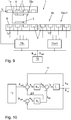
- the drive coils 7, 8 in the area of the transport unit Tn i.e. in the area in which the excitation magnets 4, 5 of the transport unit Tn and drive coils 7, 8 can interact, are energized with a stator current i A , the stator currents i A1 , i A2 of this Drive coils 7, 8 do not have to be the same. This is ensured by the associated segment control unit 11 m1 (see Fig. 9 ).
- the stator current i A1 , i A2 , or the propulsion force-forming components i Aq1 , i Aq2, of the drive coils 7, 8 generate, in cooperation with the excitation magnets 4, 5, the propulsion force F v acting on the transport unit Tn.
- the side forces F PMS1 , F PMS2 with magnetic excitation always act on both sides of the Tn transport unit due to the interaction of the magnets 4, 5 of the Tn transport unit with ferromagnetic components of the guide structure 6.
- the side forces F PMS1 , F of the magnetic excitation acting on both sides of the Tn transport unit In the normal case, with the same air gap, the same structure of the guide structure 6 on both sides, etc., PMS2 are of the same size and directed in opposite directions, so that the vector sum of the side forces F PMS1 , F PMS2 that act as magnetic excitation results in zero. In the ideal case, the transport unit Tn is therefore free from lateral forces.
- the present invention is based on the fact that the magnetic flux ⁇ or the magnetic field between the transport unit Tn and drive coils 7, 8 or the guide structure 6, which is normally caused by the permanent magnets 4, 5, is specifically influenced around the transport unit Tn to impress a steering effect L.
- the current space vector of the stator current i A responsible for the magnetic field is changed in at least one drive coil 7, 8 so that a propulsive force-generating and / or lateral force-generating electromagnetic force component arises which is superimposed on the propulsive force F V.
- the goal is usually that the acting propulsive force F V and thus the propulsive movement of the transport unit Tn is not influenced.
- the stator current i A or the resulting magnetic flux documentg not only generate the propulsive force F V required for the movement of the transport unit Tn, but also an electromagnetic force component F EMS which forms a side force, also called electromagnetic side force in the following.
- F EMS electromagnetic force component
- one of the drive coils 7, 8 cooperating with the transport unit Tn is impressed with a stator current i A which, in addition to the propulsive force-forming electromagnetic force component, which causes the propulsive force F V , a force component at right angles to it, that is, in the lateral direction.
- the electromagnetic side force F EMS is thus superimposed on the propulsive force F V.
- the components ⁇ d of the applied electromagnetic field, which cause the side force, serve here practically to weaken or strengthen the active excitation magnetic field.
- the current space vector of the stator currents i A1 , i A2 impressed in the drive coils 7, 8 are preferably regulated in such a way that the vector sum of the resulting side forces F 1 , F 2 is zero. In the ideal case, this means that the electromagnetic side forces F EMS1 , F EMS2 are equal to zero. This achieves maximum efficiency of the movement of the transport unit Tn in these areas, since all of the energy flows into the generation of the propulsive force F V.
- stator currents i A1 , i A2 are preferably impressed on both sides in such a way that the vector sum of the resulting side forces F 1 , F 2 , or the electromagnetic side forces F EMS1 , F EMS2 , are zero.
- the resulting side forces F 1 , F 2 which are thus reduced to the excitation magnetic side forces F PMS1, F PMS2 , are normally the same size and in opposite directions in the entry area of the transfer position U and thus cancel each other out.
- the stator currents i A1 , i A2 which are impressed in the drive coils 7, 8, are now changed in such a way that lateral forces F 1 , F 2 resulting from the weakening or strengthening of the permanent magnetic field on both sides of the transport unit Tn result, which are different in amount.
- the magnetic flux ⁇ is a function of the stator current i A is the responsible for the side force magnetic flux component can ⁇ d by changing the vectorial current space vector of the stator current i A at one side, or on both sides of the transport unit are changed Tn to the Generate electromagnetic side force F EMS1, F EMS2 on at least one side.
- the magnetic flux ⁇ is preferably changed in such a way that the electromagnetic side forces F EMS1 , F EMS2 on both sides of the transport unit Tn point in the same direction ( Fig. 5 ).
- the magnetic flux ⁇ could also be changed in such a way that the electromagnetic side forces F EMS1 , F EMS2 have different directions on the two sides of the transport unit Tn, but these would partly cancel each other out, which ultimately only results in higher losses would.
- the magnetic flux ⁇ of one of the active drive coils 7, 8, several of the active drive coils 7, 8 or all of the active drive coils 7, 8 can be changed . It is also conceivable to generate an electromagnetic side force F EMS1 , F EMS2 on only one side of the transport unit Tn. Only the resulting generated force of the forces acting on the transport unit Tn is decisive.
- the resulting steering force F L guides the transport unit Tn in the illustrated embodiment along the transport section Am, with which the transport unit Tn is moved straight ahead in the exit area of the transfer position U ( Fig. 4 below).
- the field is weakened on the side of the transport unit Tn along which the transport unit Tn is not to be moved, here on the drive coils 8.
- the field is strengthened on the side on which the transport unit Tn is to be moved, here on the drive coils 7.
- a steering force F L can be generated in one of the two lateral directions as the steering action L, which guides the transport unit Tn along the desired transport section Am or An.
- the direction can be determined, but in particular also the magnitude of this steering force F L at any point in time of the movement of the transport unit Tn.
- This steering force F L can also be variable over time and can also be applied to the respective transport unit Tn and also be geared to the current movement. For example, a transport unit Tn that is loaded with a heavier load or that is moving faster may require a higher steering force F L than an empty or slowly moving transport unit Tn.
- the stator currents i A1 , i A2 of the drive coils 7, 8 are preferably controlled in such a way that the desired or the higher-level system control unit 10 ( Fig. 9 ) predetermined propulsion force F V is maintained.
- the forward movement of the transport unit Tn remains unaffected by the generation of the steering effect L in the transfer position U. This can be done, for example, in the exit area from transfer position U ( Fig. 4 below), on which only the drive coils 7 on one side are active, also mean that the q-component of the stator current i A1 that causes the propulsive force F V must be increased at the same time in order to maintain the propulsive force F V.
- the propulsion force F V is generally set anyway by the position control of the transport unit Tn and it is therefore normally not necessary to intervene in this regulation of the propulsion force F V in the transfer position U.
- the transfer position U does not have to be designed as a switch, but can also be designed as a transfer from one transport section Am to another transport section An, such as the transfer position U1 in FIG Fig. 1 where, for example, there is a transition from a two-sided transport section (drive coils on both sides) to a one-sided transport section (drive coils on one side).
- a situation is exemplified by the Fig. 6 explained.
- the entrance, the transfer position and the exit can be done as in after a switch Fig. 4 be managed.
- the magnetic side force F PMS2 on the transport section An is reduced even without active control of the side force-generating current component i Ad2 of the stator current i A2 .
- the electromagnetic side force F EMS1 can be maintained for guidance reasons (for example if the excitation magnetic guidance alone is not reliably sufficient). This means that it would be sufficient here if in the area of the entrance ( Fig. 6 above) or the transfer area ( Fig. 6 Middle) the electromagnetic side force F EMS is regulated on only one side. It is not absolutely necessary to regulate the electromagnetic side forces F EMS1 , F EMS2 on both sides at the same time. The same procedure could be used for the transition from a one-sided transport section to a two-sided transport section.
- a steering torque M L acts on the transport unit Tn about the vertical axis, as in FIG Fig. 7 shown.
- This steering torque M L can now also be used as a steering action L for guiding the transport unit Tn along a desired transport section A.
- the propulsion force F v is normally regulated via the position s of the transport unit Tn along the transport route, so that the transport unit Tn is at the intended position at all times. In this way, the current speed and the acceleration of the transport unit Tn are also regulated indirectly.
- the propulsive force generating electromagnetic force components F EMV1, F EMV2 result directly from the propulsive force generating component i Aq1 , i Aq2 of the respectively impressed stator current i A1 , i A2 by multiplication with a known force constant K f .
- K f the force constant
- the propulsion force-forming components i Aq1, i Aq2 of the respectively impressed stator current i A1 , i A2 are regulated in a control system via the position error E of the transport unit Tn in order to generate the required propulsion force F V.
- a desired steering torque M can be achieved via the modification variable L.
- the propulsive force F V of the transport unit Tn is regulated by the position regulation in the form of the target position specification s 1, soll , s 2, soll.
- the steering torque M L as a steering effect L can now be used in a transfer position U in order to move the transport unit Tn along a desired transport section A, as on the basis of FIG Fig. 8 is explained.
- the transfer area ( Fig. 8 Middle) by specifying the modification variables ⁇ s 1 , ⁇ s 2, a steering torque M L is generated as described above, which leads to the transport unit Tn being guided along the transport section Am and being moved on along the transport section Am.
- the transport unit Tn In the exit area of the transfer position ( Fig. 8 below), the transport unit Tn can then be driven further on only one side as usual (as in Fig. 8 ), or a drive on both sides can be provided.
- a higher-level control unit 10 is responsible for moving the transport units Tn in the long stator linear motor along the transport route.
- the control unit 10 thus specifies the movement of the transport units Tn, for example by specifying setpoint position values s soll , and thus also controls the speed and acceleration of the transport units Tn.
- the higher-level control unit 10 is also responsible for guiding the transport units Tn along the transport device 1 responsible and thus also for the steering of the transport units Tn in transfer positions U.
- the control unit 10 thus also specifies the steering action L acting on the transport units Tn, for example by specifying setpoint values for the magnetic flux ⁇ s ⁇ ll , and thus determines the transport route along which the transport units Tn in the transport device 1 are moved.
- the higher-level control unit 10 specifies corresponding setpoint values for the position s soll and the magnetic flux ⁇ s ⁇ ll for each of the moving transport units Tn.
- Each transport segment TSn, TSn + 1, or generally a group of drive coils 7, 8 or also each drive coil 7, 8, of a transport section An is assigned a segment control unit 11 n , 11 n + 1 , which controls the drive coils 7, 8 of the respective transport segment TSn , TSn + 1 controls individually with a stator current i A. It can of course also be provided for the drive coils 7, 8 on each side to provide a separate segment control unit 11 n , 11 n + 1 , wherein the segment control units 11 n , 11 n + 1 on each side can also be connected to one another via a data line and Can exchange data with each other.
- Each segment control unit 11 n , 11 n + 1 generates a stator current i A , with which the drive coils 7, 8 are applied, from the setpoint specifications for the position s soll and the magnetic flux ⁇ soll.
- the stator current i A is a current vector (current space vector) which includes a propulsive force-forming component i Aq for generating the propulsive force F V and which causes a magnetic flux ⁇ .
- modified propulsive force-generating electromagnetic force components F EMV1, F EMV2 and / or lateral force-generating electromagnetic force components F EMS1 , F EMS2 can now be impressed via the current vectors i A1 , i A2 , which cause the required steering effect L.
- the stator current vector i A in cooperation with the excitation magnets 4, 5 of the transport unit Tn as described, generates the desired effect on the transport unit Tn at all times, in particular a propulsive force F V and possibly a steering effect L (steering force F L and / or steering torque M L ).
- a steering regulator RL for regulating the steering effect L and a position regulator RP for regulating the position s are implemented for each drive coil 7, 8, as in FIG Fig. 10 shown.
- the control of the steering action L is preferably active only in a transfer position U and takes place for example on the basis of the magnetic flux ⁇ and it will be a target flow ⁇ s ⁇ ll defined as described above. Outside of a transfer position U, only the propulsive force F V is usually regulated.
- the current actual flow ⁇ ist is recorded by measurement technology or estimated by means of a suitable observer and compared with the target flow ⁇ s ⁇ ll .
- the position controller RP regulates a position error e s , which is derived from the specified target position s soll and the current one Actual position i ist .
- the actual position i ist can be recorded by measurement or can also be determined in another suitable manner, for example again by a control-technical observer.
- the position error e s at least in a transfer position U, when the steering torque M L is used as the steering effect L , the modification amount .DELTA.s a
- the position controller RP for the regulated drive coil 7, 8 is a current component i Aq of the stator current i A which forms a propulsive force if both components of the stator current i A are present and the stator current i A determined can be impressed on the controlled system, here the transport device 1 or the parts provided, in particular the controlled drive coil 7, 8.
Landscapes
- Engineering & Computer Science (AREA)
- Power Engineering (AREA)
- Physics & Mathematics (AREA)
- Electromagnetism (AREA)
- Transportation (AREA)
- Mechanical Engineering (AREA)
- Chemical & Material Sciences (AREA)
- Combustion & Propulsion (AREA)
- Linear Motors (AREA)
- Non-Mechanical Conveyors (AREA)
- Control Of Linear Motors (AREA)
Claims (6)
- Procédé de transfert d'une unité de transport (Tn) d'un moteur linéaire à stator long dans une position de transfert (U) d'une première section de transport (Am) comportant un certain nombre de bobines d'entraînement (7, 8) disposées les unes derrière les autres sur une structure de guidage (6) dans la direction de déplacement de l'unité de transport (Tn) dans la zone de la position de transfert (U) vers une seconde section de transport (An) comportant un certain nombre de bobines d'entraînement (7, 8) disposées les unes derrière les autres sur une structure de guidage (6) dans la zone de la position de transfert (U), des aimants d'excitation (4, 5) étant disposés sur les deux côtés de l'unité de transport (Tn), lesquels aimants d'excitation coopèrent avec les bobines d'entraînement (7, 8) dans la zone de l'unité de transport (Tn), des bobines d'entraînement (7, 8) étant prévues sur les deux côtés de l'unité de transport (Tn) dans la zone de la position de transfert (U), lesquelles bobines d'entraînement peuvent coopérer avec les aimants d'excitation (4, 5) sur les deux côtés de l'unité de transport (Tn), et la seconde section de transport (An) au niveau d'une sortie d'une position de transfert (U) étant réalisée d'un côté avec des bobines d'entraînement (7, 8) sur un seul côté, lesquelles bobines d'entraînement peuvent coopérer avec les aimants d'excitation (4, 5) sur ce côté de l'unité de transport (Tn), et des forces latérales d'excitation magnétique (FPMS1, FPMS2) agissant, dans la zone de la position de transfert (U), sur l'unité de transport (Tn) des deux côtés de l'unité de transport (Tn) en raison de l'interaction des aimants d'excitation (4, 5) avec les composants ferromagnétiques de la structure de guidage (6), caractérisé en ce qu'un courant statorique (iA1, iA2) est appliqué dans au moins une bobine d'entraînement (7, 8) dans une zone de transfert de la position de transfert (U) au moins d'un côté de l'unité de transport (Tn), lequel courant statorique génère une force latérale électromagnétique (FEMS1, FEMS2) sur l'unité de transport (Tn), et en ce que les forces latérales (F1, F2) résultant des deux côtés de l'unité de transport (Tn), représentant la somme de la force latérale d'excitation magnétique (FPMS1, FPMS2) active et de la force latérale électromagnétique (FEMS1, FEMS2), varient en amplitude afin de générer un effet de direction (L), l'effet de direction (L) guidant l'unité de transport (Tn) dans la position de transfert (U) le long de la seconde section de transport (An).
- Procédé selon la revendication 1, caractérisé en ce qu'une force latérale électromagnétique (FEMS1, FEMS2) est générée des deux côtés de l'unité de transport (Tn).
- Procédé selon la revendication 2, caractérisé en ce que des forces latérales électromagnétiques (FEMS1, FEMS2) redressées sont générées des deux côtés de l'unité de transport (Tn).
- Procédé selon la revendication 2, caractérisé en ce que des forces latérales électromagnétiques (FEMS1, FEMS2) de directions différentes sont générées des deux côtés de l'unité de transport (Tn).
- Procédé selon l'une des revendications 1 à 4, caractérisé en ce que plusieurs bobines d'entraînement (7, 8) agissent conjointement avec des aimants d'excitation (4, 5) sur l'unité de transport (Tn), et un courant statorique (iA1, iA2) est appliqué dans une bobine d'entraînement (7, 8) active, dans plusieurs bobines d'entraînement (7, 8) actives ou dans toutes les bobines d'entraînement (7, 8) actives.
- Procédé selon l'une des revendications 1 à 5, caractérisé en ce qu'une force de propulsion (Fv) agissant sur l'unité de transport (Tn) est régulée par une composante de courant de formation de force de propulsion (iAq1, iAq2) du courant statorique (iA1, iA2), et l'effet de direction (L) est régulé dans la position de transfert (U) par une composante de courant de formation de force latérale (iAd1, iAd2) du courant statorique (iA1, iA2).
Applications Claiming Priority (2)
| Application Number | Priority Date | Filing Date | Title |
|---|---|---|---|
| ATA50529/2015A AT517219B1 (de) | 2015-06-23 | 2015-06-23 | Verfahren und Langstatorlinearmotor zur Übergabe einer Transporteinheit an einer Übergabeposition |
| EP16174356.2A EP3109998B1 (fr) | 2015-06-23 | 2016-06-14 | Procede et moteur lineaire a stator long destine a transferer une unite de transport a une position de transmission |
Related Parent Applications (2)
| Application Number | Title | Priority Date | Filing Date |
|---|---|---|---|
| EP16174356.2A Division EP3109998B1 (fr) | 2015-06-23 | 2016-06-14 | Procede et moteur lineaire a stator long destine a transferer une unite de transport a une position de transmission |
| EP16174356.2A Division-Into EP3109998B1 (fr) | 2015-06-23 | 2016-06-14 | Procede et moteur lineaire a stator long destine a transferer une unite de transport a une position de transmission |
Publications (2)
| Publication Number | Publication Date |
|---|---|
| EP3379719A1 EP3379719A1 (fr) | 2018-09-26 |
| EP3379719B1 true EP3379719B1 (fr) | 2021-04-14 |
Family
ID=56131404
Family Applications (2)
| Application Number | Title | Priority Date | Filing Date |
|---|---|---|---|
| EP16174356.2A Active EP3109998B1 (fr) | 2015-06-23 | 2016-06-14 | Procede et moteur lineaire a stator long destine a transferer une unite de transport a une position de transmission |
| EP18172313.1A Active EP3379719B1 (fr) | 2015-06-23 | 2016-06-14 | Procédé destinés à transferer une unité de transport à une position de transmission |
Family Applications Before (1)
| Application Number | Title | Priority Date | Filing Date |
|---|---|---|---|
| EP16174356.2A Active EP3109998B1 (fr) | 2015-06-23 | 2016-06-14 | Procede et moteur lineaire a stator long destine a transferer une unite de transport a une position de transmission |
Country Status (4)
| Country | Link |
|---|---|
| US (2) | US10622921B2 (fr) |
| EP (2) | EP3109998B1 (fr) |
| AT (1) | AT517219B1 (fr) |
| CA (1) | CA2933654A1 (fr) |
Families Citing this family (62)
| Publication number | Priority date | Publication date | Assignee | Title |
|---|---|---|---|---|
| EP4194378B1 (fr) | 2016-09-09 | 2024-11-20 | The Procter & Gamble Company | Système et procédé pour acheminer indépendamment des véhicules et distribuer des récipients et des fermetures à des stations d'exploitation unitaires |
| CN109661623A (zh) | 2016-09-09 | 2019-04-19 | 宝洁公司 | 用于在单条生产线上同时生产不同产品的方法 |
| WO2018049121A2 (fr) | 2016-09-09 | 2018-03-15 | The Procter & Gamble Company | Système et procédé de production de produits sur la base de la demande |
| MX2019002782A (es) | 2016-09-09 | 2019-09-04 | Procter & Gamble | Sistema y método para llenar simultáneamente recipientes con diferentes composiciones de fluidos. |
| US10996232B2 (en) | 2016-09-09 | 2021-05-04 | The Procter & Gamble Company | System and method for independently routing container-loaded vehicles to create different finished products |
| MX2019002780A (es) | 2016-09-09 | 2019-09-04 | Procter & Gamble | Sistema y método para llenar simultáneamente recipientes de formas y/o tamaños diferentes. |
| CN109661361B (zh) | 2016-09-09 | 2021-11-19 | 宝洁公司 | 用于创建成品的轨道系统 |
| EP4640594A3 (fr) | 2016-10-05 | 2026-03-04 | Laitram, LLC | Système de transport à moteur linéaire |
| WO2018161160A1 (fr) * | 2017-03-06 | 2018-09-13 | Ats Automation Tooling Systems Inc. | Système convoyeur à moteur linéaire avec dérouteur et procédé de conception et de configuration de celui-ci |
| FR3063983A1 (fr) * | 2017-03-17 | 2018-09-21 | C.E.R.M.E.X. Constructions Etudes Et Recherches De Materiels Pour L'emballage D'expedition | Dispositif de transfert d'objets |
| AT519664B1 (de) * | 2017-03-21 | 2018-09-15 | B & R Ind Automation Gmbh | Verfahren zur Regelung der Normalkraft einer Transporteinheit eines Langstatorlinearmotors |
| AT519829A1 (de) * | 2017-04-04 | 2018-10-15 | B & R Ind Automation Gmbh | Verfahren zum Betreiben eines Langstatorlinearmotors |
| DE102017208454A1 (de) | 2017-05-18 | 2018-11-22 | Krones Ag | Magnetweiche für ein Transportsystem |
| DE102017208455A1 (de) * | 2017-05-18 | 2018-11-22 | Krones Ag | Magnetweiche für ein Transportsystem |
| EP3642142A4 (fr) | 2017-06-19 | 2021-03-17 | Laitram, L.L.C. | Transporteur monorail à plateaux |
| AT520088B1 (de) | 2017-06-29 | 2019-01-15 | B & R Ind Automation Gmbh | Verfahren zum Betreiben einer Transporteinrichtung in Form eines Langstatorlinearmotors |
| NL2019259B1 (en) * | 2017-07-17 | 2019-01-30 | Hardt Ip B V | Switch for a track for guiding transportation of a vehicle |
| EP3457560A1 (fr) | 2017-09-14 | 2019-03-20 | B&R Industrial Automation GmbH | Moteur linéaire à stator long |
| DE102017220892A1 (de) * | 2017-11-22 | 2019-05-23 | Hamilton Bonaduz Ag | Pipettiervorrichtung mit doppelseitig nutzbarer Stator-Magnetanordnung als Teil eines linearmotorischen Antriebs einer Pipettiereinheit |
| EP3489175B1 (fr) | 2017-11-24 | 2020-02-26 | B&R Industrial Automation GmbH | Dispositif de transport sous forme d'un moteur linéaire à stator long doté d'une section de retournement |
| EP3489072B1 (fr) * | 2017-11-24 | 2022-01-19 | B&R Industrial Automation GmbH | Trajet de transport d'un moteur linéaire à stator long |
| EP3501878B1 (fr) | 2017-12-22 | 2022-07-13 | B&R Industrial Automation GmbH | Dispositif de transport sous forme d'un moteur linéaire à stator long |
| EP3517344A1 (fr) * | 2018-01-24 | 2019-07-31 | B&R Industrial Automation GmbH | Unité de transport pour un moteur linéaire à stator long |
| NL2020480B1 (en) * | 2018-02-22 | 2019-08-29 | Hardt Ip B V | Method of controlling a direction of a trajectory of a vehicle |
| DE102018202868A1 (de) * | 2018-02-26 | 2019-08-29 | Krones Ag | Verfahren und Vorrichtung zur Justage eines Transportfahrzeugs für eine Behälterbehandlungsanlage |
| EP3547512A1 (fr) * | 2018-03-28 | 2019-10-02 | KONE Corporation | Moteur électrique linéaire |
| EP3363751B1 (fr) | 2018-06-05 | 2020-04-22 | B&R Industrial Automation GmbH | Procédé de transfert d'une unité de transport d'un convoyeur à moteur linéaire à une position de transfert |
| EP3597471A1 (fr) | 2018-07-18 | 2020-01-22 | B&R Industrial Automation GmbH | Moteur linéaire à stator long |
| EP3599126B1 (fr) * | 2018-07-25 | 2021-11-10 | B&R Industrial Automation GmbH | Procédé de fonctionnement d'un moteur linéaire à stator long pourvu d'aiguillage |
| EP3599127B1 (fr) * | 2018-07-25 | 2022-10-05 | B&R Industrial Automation GmbH | Procédé de fonctionnement d'un moteur linéaire à stator long pourvu d'unités de transport et surveillance de collision |
| EP3653562B1 (fr) | 2018-11-19 | 2026-04-15 | ABB Schweiz AG | Procédé et régulateur d'oscillation permettant de réguler les oscillations d'un système technique oscillant |
| CN109533867B (zh) * | 2018-12-30 | 2023-09-08 | 南京博蓝奇智能科技有限公司 | 分段独立控制输送机及输送系统 |
| US11962214B2 (en) | 2019-05-28 | 2024-04-16 | B&R Industrial Automation GmbH | Transport device |
| US11193812B2 (en) | 2019-07-01 | 2021-12-07 | B&R Industrial Automation GmbH | Electromagnetic conveyor with weighing station |
| CN114845937A (zh) | 2019-07-30 | 2022-08-02 | 安海斯-布希英博有限公司 | 用于二次包装的成形工具 |
| CN114466796B (zh) | 2019-07-30 | 2024-04-16 | 安海斯-布希英博有限公司 | 用于二级包装的包装设备 |
| EP4003887B1 (fr) | 2019-07-30 | 2025-02-12 | Anheuser-Busch InBev S.A. | Appareil de désempilage |
| CN114502471A (zh) | 2019-07-30 | 2022-05-13 | 安海斯-布希英博有限公司 | 物品拾取和处理设备 |
| ES2982363T3 (es) | 2019-07-30 | 2024-10-15 | Anheuser Busch Inbev Sa | Aparato de envasado |
| AT523101A1 (de) | 2019-10-31 | 2021-05-15 | B & R Ind Automation Gmbh | Transporteinrichtung in Form eines Langstatorlinearmotors |
| AT523102A1 (de) | 2019-10-31 | 2021-05-15 | B & R Ind Automation Gmbh | Transporteinrichtung in Form eines Langstatorlinearmotors |
| JP2023504039A (ja) * | 2019-11-27 | 2023-02-01 | ベーウントエル・インダストリアル・オートメイション・ゲゼルシャフト・ミト・ベシュレンクテル・ハフツング | 運搬機器 |
| DE102020120295A1 (de) | 2020-07-31 | 2022-02-03 | Krones Aktiengesellschaft | Vorrichtung zum Ausstatten von Behältern |
| DE102020120290A1 (de) | 2020-07-31 | 2022-02-03 | Krones Aktiengesellschaft | Vorrichtung zum Bedrucken oder Etikettieren von Behältern |
| EP4208941B1 (fr) | 2020-09-03 | 2024-11-13 | B&R Industrial Automation GmbH | Procédé de fonctionnement d'un moteur linéaire, et moteur linéaire |
| DE102020131035A1 (de) | 2020-11-24 | 2022-05-25 | Beckhoff Automation Gmbh | Lineares Transportsystem mit Objektübergabe |
| AT524046B1 (de) | 2020-12-01 | 2022-02-15 | B & R Ind Automation Gmbh | Transporteinrichtung in Form eines Langstatorlinearmotors |
| WO2022125292A1 (fr) | 2020-12-11 | 2022-06-16 | Laitram, L.L.C. | Système de transfert de convoyeur |
| AT524925A1 (de) | 2021-03-25 | 2022-10-15 | B & R Ind Automation Gmbh | Verfahren zum Betreiben einer Transportanlage in Form eines Langstatorlinearmotors |
| CN113734720B (zh) * | 2021-09-13 | 2022-06-24 | 浙江大学先进电气装备创新中心 | 直驱式多轨柔性输送系统及其控制方法 |
| BR102021018108A2 (pt) | 2021-09-13 | 2023-03-28 | Freed Participaçoes S/A | Esteira transportadora tracionada por motor de indução linear com primário de dupla face e secundário longo seccionado |
| US12246871B2 (en) | 2021-09-23 | 2025-03-11 | Sargento Cheese Inc. | Horizontal form, fill and seal machine and method of using same |
| WO2023186856A1 (fr) | 2022-03-28 | 2023-10-05 | B&R Industrial Automation GmbH | Unité de transport et procédé d'installation correspondant |
| KR20250008880A (ko) | 2022-04-13 | 2025-01-16 | 아프레시아 파마슈티칼즈 엘엘씨 | 전방향 자기 운동 장치를 이용한 적층 제조를 위한 시스템 및 방법 |
| EP4391352A1 (fr) | 2022-12-23 | 2024-06-26 | Siemens Aktiengesellschaft | Procédé de commande d'un système de transport basé sur un moteur linéaire et système de transport |
| DE102023110521A1 (de) | 2023-04-25 | 2024-10-31 | Beckhoff Automation Gmbh | Lineares Transportsystem |
| CN116176634B (zh) * | 2023-04-27 | 2023-07-14 | 成都西交华创科技有限公司 | 一种轨道板式运载系统及运载方法 |
| US12121936B1 (en) | 2023-05-31 | 2024-10-22 | General Mills, Inc. | Processing system for handling pieces of product |
| CN119738885A (zh) | 2023-09-22 | 2025-04-01 | Abb瑞士股份有限公司 | 用于探测动子的方法和电磁运输装置 |
| US12545506B2 (en) * | 2023-12-11 | 2026-02-10 | Rockwell Automation Technologies, Inc. | System for zero radius direction change in an independent cart system |
| EP4624225A1 (fr) | 2024-03-29 | 2025-10-01 | ABB Schweiz AG | Moteur linéaire à transfert de puissance capacitif |
| EP4647374A1 (fr) | 2024-05-10 | 2025-11-12 | ABB Schweiz AG | Procédé et système de transport pour déterminer la position d'une navette |
Family Cites Families (15)
| Publication number | Priority date | Publication date | Assignee | Title |
|---|---|---|---|---|
| FR1596424A (fr) | 1968-12-26 | 1970-06-15 | ||
| DE4133114C2 (de) | 1991-10-05 | 1996-11-21 | Michael Rupp | Fördersystem für Stückgut |
| FR2730876A1 (fr) | 1995-02-21 | 1996-08-23 | Pincon Sa | Moteur electrique lineaire dont la partie passive est constituee par les objets a deplacer et installation de transitique industrielle utilisant un tel moteur |
| US5904101A (en) * | 1997-04-22 | 1999-05-18 | Power Superconductor Applications Co., Inc. | Auxiliary propulsion for magnetically levitated vehicle |
| US6101952A (en) | 1997-12-24 | 2000-08-15 | Magnemotion, Inc. | Vehicle guidance and switching via magnetic forces |
| EP2747257A3 (fr) * | 2002-06-05 | 2016-06-29 | Jacobs Automation, Inc. | Système de déplacement commandé |
| WO2004103972A1 (fr) | 2003-05-20 | 2004-12-02 | Ajinomoto Co.,Inc. | Nouveau derive de piperidine |
| JP2007501159A (ja) | 2003-05-21 | 2007-01-25 | シーアホルツ−トランスリフト・シュヴァイツ・アクチエンゲゼルシャフト | 線路,転轍器及び磁歪式センサを有する輸送設備 |
| KR20070011577A (ko) * | 2004-05-07 | 2007-01-24 | 마그네모션, 인코포레이티드 | 단일 경로를 기반으로 하는 작용기들을 이용한 3차원 동작 |
| US9032880B2 (en) * | 2009-01-23 | 2015-05-19 | Magnemotion, Inc. | Transport system powered by short block linear synchronous motors and switching mechanism |
| EP2634913A4 (fr) | 2010-10-26 | 2017-02-22 | Murata Machinery, Ltd. | Système de moteur linéaire réparti |
| DE102012204919A1 (de) | 2012-03-27 | 2013-10-02 | Beckhoff Automation Gmbh | Statorvorrichtung für einen linearmotor und lineares transportsystem |
| DE102013218389B4 (de) | 2013-09-13 | 2023-01-12 | Krones Ag | Vorrichtung und Verfahren zum Schalten einer passiven Weiche für Transportsysteme mit Linearmotoren |
| US9802507B2 (en) | 2013-09-21 | 2017-10-31 | Magnemotion, Inc. | Linear motor transport for packaging and other uses |
| CN104578673A (zh) | 2013-10-09 | 2015-04-29 | 徐建宁 | 平板直线电机 |
-
2015
- 2015-06-23 AT ATA50529/2015A patent/AT517219B1/de not_active IP Right Cessation
-
2016
- 2016-06-14 EP EP16174356.2A patent/EP3109998B1/fr active Active
- 2016-06-14 EP EP18172313.1A patent/EP3379719B1/fr active Active
- 2016-06-21 CA CA2933654A patent/CA2933654A1/fr not_active Abandoned
- 2016-06-22 US US15/189,416 patent/US10622921B2/en active Active
-
2018
- 2018-07-16 US US16/036,399 patent/US10917027B2/en active Active
Non-Patent Citations (1)
| Title |
|---|
| None * |
Also Published As
| Publication number | Publication date |
|---|---|
| US10917027B2 (en) | 2021-02-09 |
| EP3379719A1 (fr) | 2018-09-26 |
| EP3109998A1 (fr) | 2016-12-28 |
| AT517219B1 (de) | 2016-12-15 |
| US20180323732A1 (en) | 2018-11-08 |
| US20160380562A1 (en) | 2016-12-29 |
| CA2933654A1 (fr) | 2016-12-23 |
| EP3109998B1 (fr) | 2019-08-07 |
| US10622921B2 (en) | 2020-04-14 |
| AT517219A4 (de) | 2016-12-15 |
Similar Documents
| Publication | Publication Date | Title |
|---|---|---|
| EP3379719B1 (fr) | Procédé destinés à transferer une unité de transport à une position de transmission | |
| EP3363751B1 (fr) | Procédé de transfert d'une unité de transport d'un convoyeur à moteur linéaire à une position de transfert | |
| EP3978300B1 (fr) | Procédé de réglage de la force normale d'une unité de transport d'un moteur linéaire à stator longs | |
| EP3385803B1 (fr) | Procédé de fonctionnement d'un moteur linéaire à stator déployé | |
| EP3547530B1 (fr) | Procédé de fonctionnement d'un dispositif de transport en forme de moteur linéaire à stator long | |
| EP3521219B1 (fr) | Dispositif de transport et procédé d'ajustement d'un dispositif de transport | |
| EP3599127B1 (fr) | Procédé de fonctionnement d'un moteur linéaire à stator long pourvu d'unités de transport et surveillance de collision | |
| EP3489175B1 (fr) | Dispositif de transport sous forme d'un moteur linéaire à stator long doté d'une section de retournement | |
| AT518734B1 (de) | Verfahren zum Betreiben eines Langstatorlinearmotors | |
| EP2141019B1 (fr) | Procédé de séparation d'au moins deux ponts d'un système de transport segmenté pour matières d'impression | |
| AT518733A1 (de) | Verfahren zum Betreiben eines Langstatorlinearmotors | |
| EP3625080B1 (fr) | Aiguille magnétique destinée à un système de transport | |
| EP4098473A1 (fr) | Installation de transport et procédé permettant de faire fonctionner une installation de transport ayant une surveillance de collisions | |
| EP3489072B1 (fr) | Trajet de transport d'un moteur linéaire à stator long | |
| EP3447904B1 (fr) | Commande de bobines de moteur linéaire à stator déployé d'un stator de moteur linéaire à stator déployé | |
| EP3425780A1 (fr) | Dispositif de transport sous forme d'un moteur linéaire à stator long | |
| EP3575250A1 (fr) | Procédé de commande d'une unité de transport d'un dispositif de transport sous la forme d'un moteur linéaire à stator long | |
| EP3810532A1 (fr) | Ensemble de transport pour moteur linéaire à long stator | |
| EP4064549A1 (fr) | Procédé de fonctionnement d'une installation de transport sous la forme d'un moteur linéaire à stator long | |
| EP3625079B1 (fr) | Aiguillage magnétique pour un système de transport | |
| EP3569528B1 (fr) | Système de transport | |
| WO2019101988A1 (fr) | Système de transport par machines à flux transversal, chariot de transport et procédé | |
| EP4591425A1 (fr) | Procédé de commande d'un système de transport basé sur un moteur linéaire et système de transport | |
| CH548331A (de) | Rollgestellanlage fuer das einbringen und entnehmen von waren mittels schienengefuehrten stapeleinrichtungen. |
Legal Events
| Date | Code | Title | Description |
|---|---|---|---|
| PUAI | Public reference made under article 153(3) epc to a published international application that has entered the european phase |
Free format text: ORIGINAL CODE: 0009012 |
|
| STAA | Information on the status of an ep patent application or granted ep patent |
Free format text: STATUS: THE APPLICATION HAS BEEN PUBLISHED |
|
| AC | Divisional application: reference to earlier application |
Ref document number: 3109998 Country of ref document: EP Kind code of ref document: P |
|
| AK | Designated contracting states |
Kind code of ref document: A1 Designated state(s): AL AT BE BG CH CY CZ DE DK EE ES FI FR GB GR HR HU IE IS IT LI LT LU LV MC MK MT NL NO PL PT RO RS SE SI SK SM TR |
|
| STAA | Information on the status of an ep patent application or granted ep patent |
Free format text: STATUS: REQUEST FOR EXAMINATION WAS MADE |
|
| 17P | Request for examination filed |
Effective date: 20180921 |
|
| STAA | Information on the status of an ep patent application or granted ep patent |
Free format text: STATUS: EXAMINATION IS IN PROGRESS |
|
| 17Q | First examination report despatched |
Effective date: 20200527 |
|
| GRAP | Despatch of communication of intention to grant a patent |
Free format text: ORIGINAL CODE: EPIDOSNIGR1 |
|
| STAA | Information on the status of an ep patent application or granted ep patent |
Free format text: STATUS: GRANT OF PATENT IS INTENDED |
|
| RIC1 | Information provided on ipc code assigned before grant |
Ipc: H02P 21/06 20160101AFI20201113BHEP Ipc: B60L 13/00 20060101ALN20201113BHEP Ipc: B65G 54/02 20060101ALI20201113BHEP Ipc: E01B 25/34 20060101ALN20201113BHEP Ipc: H02P 21/12 20160101ALI20201113BHEP Ipc: H02K 41/03 20060101ALI20201113BHEP Ipc: E01B 25/12 20060101ALN20201113BHEP Ipc: H02P 25/064 20160101ALI20201113BHEP Ipc: H02P 25/062 20160101ALI20201113BHEP Ipc: B60L 13/03 20060101ALI20201113BHEP |
|
| INTG | Intention to grant announced |
Effective date: 20201214 |
|
| GRAS | Grant fee paid |
Free format text: ORIGINAL CODE: EPIDOSNIGR3 |
|
| GRAA | (expected) grant |
Free format text: ORIGINAL CODE: 0009210 |
|
| STAA | Information on the status of an ep patent application or granted ep patent |
Free format text: STATUS: THE PATENT HAS BEEN GRANTED |
|
| AC | Divisional application: reference to earlier application |
Ref document number: 3109998 Country of ref document: EP Kind code of ref document: P |
|
| AK | Designated contracting states |
Kind code of ref document: B1 Designated state(s): AL AT BE BG CH CY CZ DE DK EE ES FI FR GB GR HR HU IE IS IT LI LT LU LV MC MK MT NL NO PL PT RO RS SE SI SK SM TR |
|
| REG | Reference to a national code |
Ref country code: GB Ref legal event code: FG4D Free format text: NOT ENGLISH |
|
| REG | Reference to a national code |
Ref country code: CH Ref legal event code: EP |
|
| REG | Reference to a national code |
Ref country code: CH Ref legal event code: NV Representative=s name: VALIPAT S.A. C/O BOVARD SA NEUCHATEL, CH |
|
| REG | Reference to a national code |
Ref country code: DE Ref legal event code: R096 Ref document number: 502016012838 Country of ref document: DE |
|
| REG | Reference to a national code |
Ref country code: IE Ref legal event code: FG4D Free format text: LANGUAGE OF EP DOCUMENT: GERMAN |
|
| REG | Reference to a national code |
Ref country code: AT Ref legal event code: REF Ref document number: 1383364 Country of ref document: AT Kind code of ref document: T Effective date: 20210515 |
|
| REG | Reference to a national code |
Ref country code: SE Ref legal event code: TRGR |
|
| REG | Reference to a national code |
Ref country code: LT Ref legal event code: MG9D |
|
| PGFP | Annual fee paid to national office [announced via postgrant information from national office to epo] |
Ref country code: GB Payment date: 20210525 Year of fee payment: 6 Ref country code: SE Payment date: 20210531 Year of fee payment: 6 Ref country code: AT Payment date: 20210519 Year of fee payment: 6 Ref country code: CH Payment date: 20210520 Year of fee payment: 6 |
|
| REG | Reference to a national code |
Ref country code: NL Ref legal event code: MP Effective date: 20210414 |
|
| PG25 | Lapsed in a contracting state [announced via postgrant information from national office to epo] |
Ref country code: FI Free format text: LAPSE BECAUSE OF FAILURE TO SUBMIT A TRANSLATION OF THE DESCRIPTION OR TO PAY THE FEE WITHIN THE PRESCRIBED TIME-LIMIT Effective date: 20210414 Ref country code: HR Free format text: LAPSE BECAUSE OF FAILURE TO SUBMIT A TRANSLATION OF THE DESCRIPTION OR TO PAY THE FEE WITHIN THE PRESCRIBED TIME-LIMIT Effective date: 20210414 Ref country code: LT Free format text: LAPSE BECAUSE OF FAILURE TO SUBMIT A TRANSLATION OF THE DESCRIPTION OR TO PAY THE FEE WITHIN THE PRESCRIBED TIME-LIMIT Effective date: 20210414 Ref country code: NL Free format text: LAPSE BECAUSE OF FAILURE TO SUBMIT A TRANSLATION OF THE DESCRIPTION OR TO PAY THE FEE WITHIN THE PRESCRIBED TIME-LIMIT Effective date: 20210414 Ref country code: BG Free format text: LAPSE BECAUSE OF FAILURE TO SUBMIT A TRANSLATION OF THE DESCRIPTION OR TO PAY THE FEE WITHIN THE PRESCRIBED TIME-LIMIT Effective date: 20210714 |
|
| PG25 | Lapsed in a contracting state [announced via postgrant information from national office to epo] |
Ref country code: IS Free format text: LAPSE BECAUSE OF FAILURE TO SUBMIT A TRANSLATION OF THE DESCRIPTION OR TO PAY THE FEE WITHIN THE PRESCRIBED TIME-LIMIT Effective date: 20210814 Ref country code: GR Free format text: LAPSE BECAUSE OF FAILURE TO SUBMIT A TRANSLATION OF THE DESCRIPTION OR TO PAY THE FEE WITHIN THE PRESCRIBED TIME-LIMIT Effective date: 20210715 Ref country code: LV Free format text: LAPSE BECAUSE OF FAILURE TO SUBMIT A TRANSLATION OF THE DESCRIPTION OR TO PAY THE FEE WITHIN THE PRESCRIBED TIME-LIMIT Effective date: 20210414 Ref country code: PL Free format text: LAPSE BECAUSE OF FAILURE TO SUBMIT A TRANSLATION OF THE DESCRIPTION OR TO PAY THE FEE WITHIN THE PRESCRIBED TIME-LIMIT Effective date: 20210414 Ref country code: NO Free format text: LAPSE BECAUSE OF FAILURE TO SUBMIT A TRANSLATION OF THE DESCRIPTION OR TO PAY THE FEE WITHIN THE PRESCRIBED TIME-LIMIT Effective date: 20210714 Ref country code: PT Free format text: LAPSE BECAUSE OF FAILURE TO SUBMIT A TRANSLATION OF THE DESCRIPTION OR TO PAY THE FEE WITHIN THE PRESCRIBED TIME-LIMIT Effective date: 20210816 Ref country code: RS Free format text: LAPSE BECAUSE OF FAILURE TO SUBMIT A TRANSLATION OF THE DESCRIPTION OR TO PAY THE FEE WITHIN THE PRESCRIBED TIME-LIMIT Effective date: 20210414 |
|
| REG | Reference to a national code |
Ref country code: DE Ref legal event code: R097 Ref document number: 502016012838 Country of ref document: DE |
|
| PG25 | Lapsed in a contracting state [announced via postgrant information from national office to epo] |
Ref country code: SK Free format text: LAPSE BECAUSE OF FAILURE TO SUBMIT A TRANSLATION OF THE DESCRIPTION OR TO PAY THE FEE WITHIN THE PRESCRIBED TIME-LIMIT Effective date: 20210414 Ref country code: SM Free format text: LAPSE BECAUSE OF FAILURE TO SUBMIT A TRANSLATION OF THE DESCRIPTION OR TO PAY THE FEE WITHIN THE PRESCRIBED TIME-LIMIT Effective date: 20210414 Ref country code: ES Free format text: LAPSE BECAUSE OF FAILURE TO SUBMIT A TRANSLATION OF THE DESCRIPTION OR TO PAY THE FEE WITHIN THE PRESCRIBED TIME-LIMIT Effective date: 20210414 Ref country code: EE Free format text: LAPSE BECAUSE OF FAILURE TO SUBMIT A TRANSLATION OF THE DESCRIPTION OR TO PAY THE FEE WITHIN THE PRESCRIBED TIME-LIMIT Effective date: 20210414 Ref country code: RO Free format text: LAPSE BECAUSE OF FAILURE TO SUBMIT A TRANSLATION OF THE DESCRIPTION OR TO PAY THE FEE WITHIN THE PRESCRIBED TIME-LIMIT Effective date: 20210414 Ref country code: MC Free format text: LAPSE BECAUSE OF FAILURE TO SUBMIT A TRANSLATION OF THE DESCRIPTION OR TO PAY THE FEE WITHIN THE PRESCRIBED TIME-LIMIT Effective date: 20210414 Ref country code: DK Free format text: LAPSE BECAUSE OF FAILURE TO SUBMIT A TRANSLATION OF THE DESCRIPTION OR TO PAY THE FEE WITHIN THE PRESCRIBED TIME-LIMIT Effective date: 20210414 Ref country code: CZ Free format text: LAPSE BECAUSE OF FAILURE TO SUBMIT A TRANSLATION OF THE DESCRIPTION OR TO PAY THE FEE WITHIN THE PRESCRIBED TIME-LIMIT Effective date: 20210414 |
|
| PLBE | No opposition filed within time limit |
Free format text: ORIGINAL CODE: 0009261 |
|
| STAA | Information on the status of an ep patent application or granted ep patent |
Free format text: STATUS: NO OPPOSITION FILED WITHIN TIME LIMIT |
|
| REG | Reference to a national code |
Ref country code: BE Ref legal event code: MM Effective date: 20210630 |
|
| 26N | No opposition filed |
Effective date: 20220117 |
|
| PG25 | Lapsed in a contracting state [announced via postgrant information from national office to epo] |
Ref country code: LU Free format text: LAPSE BECAUSE OF NON-PAYMENT OF DUE FEES Effective date: 20210614 |
|
| PG25 | Lapsed in a contracting state [announced via postgrant information from national office to epo] |
Ref country code: IE Free format text: LAPSE BECAUSE OF NON-PAYMENT OF DUE FEES Effective date: 20210614 |
|
| PG25 | Lapsed in a contracting state [announced via postgrant information from national office to epo] |
Ref country code: IS Free format text: LAPSE BECAUSE OF FAILURE TO SUBMIT A TRANSLATION OF THE DESCRIPTION OR TO PAY THE FEE WITHIN THE PRESCRIBED TIME-LIMIT Effective date: 20210814 Ref country code: AL Free format text: LAPSE BECAUSE OF FAILURE TO SUBMIT A TRANSLATION OF THE DESCRIPTION OR TO PAY THE FEE WITHIN THE PRESCRIBED TIME-LIMIT Effective date: 20210414 |
|
| PG25 | Lapsed in a contracting state [announced via postgrant information from national office to epo] |
Ref country code: BE Free format text: LAPSE BECAUSE OF NON-PAYMENT OF DUE FEES Effective date: 20210630 |
|
| REG | Reference to a national code |
Ref country code: CH Ref legal event code: PL Ref country code: SE Ref legal event code: EUG |
|
| REG | Reference to a national code |
Ref country code: AT Ref legal event code: MM01 Ref document number: 1383364 Country of ref document: AT Kind code of ref document: T Effective date: 20220614 |
|
| GBPC | Gb: european patent ceased through non-payment of renewal fee |
Effective date: 20220614 |
|
| PG25 | Lapsed in a contracting state [announced via postgrant information from national office to epo] |
Ref country code: SE Free format text: LAPSE BECAUSE OF NON-PAYMENT OF DUE FEES Effective date: 20220615 Ref country code: LI Free format text: LAPSE BECAUSE OF NON-PAYMENT OF DUE FEES Effective date: 20220630 Ref country code: CH Free format text: LAPSE BECAUSE OF NON-PAYMENT OF DUE FEES Effective date: 20220630 Ref country code: AT Free format text: LAPSE BECAUSE OF NON-PAYMENT OF DUE FEES Effective date: 20220614 |
|
| PG25 | Lapsed in a contracting state [announced via postgrant information from national office to epo] |
Ref country code: GB Free format text: LAPSE BECAUSE OF NON-PAYMENT OF DUE FEES Effective date: 20220614 |
|
| PG25 | Lapsed in a contracting state [announced via postgrant information from national office to epo] |
Ref country code: CY Free format text: LAPSE BECAUSE OF FAILURE TO SUBMIT A TRANSLATION OF THE DESCRIPTION OR TO PAY THE FEE WITHIN THE PRESCRIBED TIME-LIMIT Effective date: 20210414 |
|
| P01 | Opt-out of the competence of the unified patent court (upc) registered |
Effective date: 20230615 |
|
| PG25 | Lapsed in a contracting state [announced via postgrant information from national office to epo] |
Ref country code: HU Free format text: LAPSE BECAUSE OF FAILURE TO SUBMIT A TRANSLATION OF THE DESCRIPTION OR TO PAY THE FEE WITHIN THE PRESCRIBED TIME-LIMIT; INVALID AB INITIO Effective date: 20160614 |
|
| PG25 | Lapsed in a contracting state [announced via postgrant information from national office to epo] |
Ref country code: MK Free format text: LAPSE BECAUSE OF FAILURE TO SUBMIT A TRANSLATION OF THE DESCRIPTION OR TO PAY THE FEE WITHIN THE PRESCRIBED TIME-LIMIT Effective date: 20210414 |
|
| PG25 | Lapsed in a contracting state [announced via postgrant information from national office to epo] |
Ref country code: TR Free format text: LAPSE BECAUSE OF FAILURE TO SUBMIT A TRANSLATION OF THE DESCRIPTION OR TO PAY THE FEE WITHIN THE PRESCRIBED TIME-LIMIT Effective date: 20210414 |
|
| PG25 | Lapsed in a contracting state [announced via postgrant information from national office to epo] |
Ref country code: MT Free format text: LAPSE BECAUSE OF FAILURE TO SUBMIT A TRANSLATION OF THE DESCRIPTION OR TO PAY THE FEE WITHIN THE PRESCRIBED TIME-LIMIT Effective date: 20210414 |
|
| REG | Reference to a national code |
Ref country code: DE Ref legal event code: R081 Ref document number: 502016012838 Country of ref document: DE Owner name: ABB SCHWEIZ AG, CH Free format text: FORMER OWNER: B&R INDUSTRIAL AUTOMATION GMBH, EGGELSBERG, AT |
|
| PGFP | Annual fee paid to national office [announced via postgrant information from national office to epo] |
Ref country code: DE Payment date: 20250618 Year of fee payment: 10 |
|
| PGFP | Annual fee paid to national office [announced via postgrant information from national office to epo] |
Ref country code: FR Payment date: 20250625 Year of fee payment: 10 |
|
| PGFP | Annual fee paid to national office [announced via postgrant information from national office to epo] |
Ref country code: IT Payment date: 20250624 Year of fee payment: 10 |