EP3380285B1 - Dispositif pour processer des materiaux en bande - Google Patents
Dispositif pour processer des materiaux en bande Download PDFInfo
- Publication number
- EP3380285B1 EP3380285B1 EP16804728.0A EP16804728A EP3380285B1 EP 3380285 B1 EP3380285 B1 EP 3380285B1 EP 16804728 A EP16804728 A EP 16804728A EP 3380285 B1 EP3380285 B1 EP 3380285B1
- Authority
- EP
- European Patent Office
- Prior art keywords
- cylinder
- openings
- transport
- transport cylinder
- elevator
- Prior art date
- Legal status (The legal status is an assumption and is not a legal conclusion. Google has not performed a legal analysis and makes no representation as to the accuracy of the status listed.)
- Active
Links
Images


















Classifications
-
- B—PERFORMING OPERATIONS; TRANSPORTING
- B26—HAND CUTTING TOOLS; CUTTING; SEVERING
- B26D—CUTTING; DETAILS COMMON TO MACHINES FOR PERFORATING, PUNCHING, CUTTING-OUT, STAMPING-OUT OR SEVERING
- B26D7/00—Details of apparatus for cutting, cutting-out, stamping-out, punching, perforating, or severing by means other than cutting
- B26D7/18—Means for removing cut-out material or waste
- B26D7/1845—Means for removing cut-out material or waste by non mechanical means
- B26D7/1863—Means for removing cut-out material or waste by non mechanical means by suction
-
- B—PERFORMING OPERATIONS; TRANSPORTING
- B26—HAND CUTTING TOOLS; CUTTING; SEVERING
- B26D—CUTTING; DETAILS COMMON TO MACHINES FOR PERFORATING, PUNCHING, CUTTING-OUT, STAMPING-OUT OR SEVERING
- B26D1/00—Cutting through work characterised by the nature or movement of the cutting member or particular materials not otherwise provided for; Apparatus or machines therefor; Cutting members therefor
- B26D1/01—Cutting through work characterised by the nature or movement of the cutting member or particular materials not otherwise provided for; Apparatus or machines therefor; Cutting members therefor involving a cutting member which does not travel with the work
- B26D1/12—Cutting through work characterised by the nature or movement of the cutting member or particular materials not otherwise provided for; Apparatus or machines therefor; Cutting members therefor involving a cutting member which does not travel with the work having a cutting member moving about an axis
- B26D1/25—Cutting through work characterised by the nature or movement of the cutting member or particular materials not otherwise provided for; Apparatus or machines therefor; Cutting members therefor involving a cutting member which does not travel with the work having a cutting member moving about an axis with a non-circular cutting member
- B26D1/34—Cutting through work characterised by the nature or movement of the cutting member or particular materials not otherwise provided for; Apparatus or machines therefor; Cutting members therefor involving a cutting member which does not travel with the work having a cutting member moving about an axis with a non-circular cutting member moving about an axis parallel to the line of cut
- B26D1/40—Cutting through work characterised by the nature or movement of the cutting member or particular materials not otherwise provided for; Apparatus or machines therefor; Cutting members therefor involving a cutting member which does not travel with the work having a cutting member moving about an axis with a non-circular cutting member moving about an axis parallel to the line of cut and coacting with a rotary member
- B26D1/405—Cutting through work characterised by the nature or movement of the cutting member or particular materials not otherwise provided for; Apparatus or machines therefor; Cutting members therefor involving a cutting member which does not travel with the work having a cutting member moving about an axis with a non-circular cutting member moving about an axis parallel to the line of cut and coacting with a rotary member for thin material, e.g. for sheets, strips or the like
-
- B—PERFORMING OPERATIONS; TRANSPORTING
- B26—HAND CUTTING TOOLS; CUTTING; SEVERING
- B26D—CUTTING; DETAILS COMMON TO MACHINES FOR PERFORATING, PUNCHING, CUTTING-OUT, STAMPING-OUT OR SEVERING
- B26D7/00—Details of apparatus for cutting, cutting-out, stamping-out, punching, perforating, or severing by means other than cutting
- B26D7/01—Means for holding or positioning work
- B26D7/018—Holding the work by suction
-
- B—PERFORMING OPERATIONS; TRANSPORTING
- B26—HAND CUTTING TOOLS; CUTTING; SEVERING
- B26D—CUTTING; DETAILS COMMON TO MACHINES FOR PERFORATING, PUNCHING, CUTTING-OUT, STAMPING-OUT OR SEVERING
- B26D7/00—Details of apparatus for cutting, cutting-out, stamping-out, punching, perforating, or severing by means other than cutting
- B26D7/18—Means for removing cut-out material or waste
-
- B—PERFORMING OPERATIONS; TRANSPORTING
- B26—HAND CUTTING TOOLS; CUTTING; SEVERING
- B26D—CUTTING; DETAILS COMMON TO MACHINES FOR PERFORATING, PUNCHING, CUTTING-OUT, STAMPING-OUT OR SEVERING
- B26D7/00—Details of apparatus for cutting, cutting-out, stamping-out, punching, perforating, or severing by means other than cutting
- B26D7/18—Means for removing cut-out material or waste
- B26D7/1845—Means for removing cut-out material or waste by non mechanical means
- B26D7/1854—Means for removing cut-out material or waste by non mechanical means by air under pressure
-
- B—PERFORMING OPERATIONS; TRANSPORTING
- B26—HAND CUTTING TOOLS; CUTTING; SEVERING
- B26D—CUTTING; DETAILS COMMON TO MACHINES FOR PERFORATING, PUNCHING, CUTTING-OUT, STAMPING-OUT OR SEVERING
- B26D7/00—Details of apparatus for cutting, cutting-out, stamping-out, punching, perforating, or severing by means other than cutting
- B26D7/26—Means for mounting or adjusting the cutting member; Means for adjusting the stroke of the cutting member
- B26D7/2628—Means for adjusting the position of the cutting member
- B26D7/265—Journals, bearings or supports for positioning rollers or cylinders relatively to each other
-
- B—PERFORMING OPERATIONS; TRANSPORTING
- B26—HAND CUTTING TOOLS; CUTTING; SEVERING
- B26F—PERFORATING; PUNCHING; CUTTING-OUT; STAMPING-OUT; SEVERING BY MEANS OTHER THAN CUTTING
- B26F1/00—Perforating; Punching; Cutting-out; Stamping-out; Apparatus therefor
- B26F1/0092—Perforating means specially adapted for printing machines
-
- B—PERFORMING OPERATIONS; TRANSPORTING
- B26—HAND CUTTING TOOLS; CUTTING; SEVERING
- B26F—PERFORATING; PUNCHING; CUTTING-OUT; STAMPING-OUT; SEVERING BY MEANS OTHER THAN CUTTING
- B26F1/00—Perforating; Punching; Cutting-out; Stamping-out; Apparatus therefor
- B26F1/38—Cutting-out; Stamping-out
- B26F1/384—Cutting-out; Stamping-out using rotating drums
-
- B—PERFORMING OPERATIONS; TRANSPORTING
- B26—HAND CUTTING TOOLS; CUTTING; SEVERING
- B26F—PERFORATING; PUNCHING; CUTTING-OUT; STAMPING-OUT; SEVERING BY MEANS OTHER THAN CUTTING
- B26F1/00—Perforating; Punching; Cutting-out; Stamping-out; Apparatus therefor
- B26F1/38—Cutting-out; Stamping-out
- B26F1/44—Cutters therefor; Dies therefor
-
- B—PERFORMING OPERATIONS; TRANSPORTING
- B41—PRINTING; LINING MACHINES; TYPEWRITERS; STAMPS
- B41F—PRINTING MACHINES OR PRESSES
- B41F19/00—Apparatus or machines for carrying out printing operations combined with other operations
- B41F19/001—Apparatus or machines for carrying out printing operations combined with other operations with means for coating or laminating
-
- B—PERFORMING OPERATIONS; TRANSPORTING
- B41—PRINTING; LINING MACHINES; TYPEWRITERS; STAMPS
- B41F—PRINTING MACHINES OR PRESSES
- B41F19/00—Apparatus or machines for carrying out printing operations combined with other operations
- B41F19/007—Apparatus or machines for carrying out printing operations combined with other operations with selective printing mechanisms, e.g. ink-jet or thermal printers
-
- B—PERFORMING OPERATIONS; TRANSPORTING
- B41—PRINTING; LINING MACHINES; TYPEWRITERS; STAMPS
- B41F—PRINTING MACHINES OR PRESSES
- B41F19/00—Apparatus or machines for carrying out printing operations combined with other operations
- B41F19/008—Apparatus or machines for carrying out printing operations combined with other operations with means for stamping or cutting out
-
- B—PERFORMING OPERATIONS; TRANSPORTING
- B41—PRINTING; LINING MACHINES; TYPEWRITERS; STAMPS
- B41F—PRINTING MACHINES OR PRESSES
- B41F19/00—Apparatus or machines for carrying out printing operations combined with other operations
- B41F19/02—Apparatus or machines for carrying out printing operations combined with other operations with embossing
- B41F19/06—Printing and embossing between a negative and a positive forme after inking and wiping the negative forme; Printing from an ink band treated with colour or "gold"
- B41F19/062—Presses of the rotary type
-
- B—PERFORMING OPERATIONS; TRANSPORTING
- B65—CONVEYING; PACKING; STORING; HANDLING THIN OR FILAMENTARY MATERIAL
- B65H—HANDLING THIN OR FILAMENTARY MATERIAL, e.g. SHEETS, WEBS, CABLES
- B65H20/00—Advancing webs
-
- B—PERFORMING OPERATIONS; TRANSPORTING
- B65—CONVEYING; PACKING; STORING; HANDLING THIN OR FILAMENTARY MATERIAL
- B65H—HANDLING THIN OR FILAMENTARY MATERIAL, e.g. SHEETS, WEBS, CABLES
- B65H20/00—Advancing webs
- B65H20/12—Advancing webs by suction roller
-
- B—PERFORMING OPERATIONS; TRANSPORTING
- B26—HAND CUTTING TOOLS; CUTTING; SEVERING
- B26D—CUTTING; DETAILS COMMON TO MACHINES FOR PERFORATING, PUNCHING, CUTTING-OUT, STAMPING-OUT OR SEVERING
- B26D7/00—Details of apparatus for cutting, cutting-out, stamping-out, punching, perforating, or severing by means other than cutting
- B26D7/26—Means for mounting or adjusting the cutting member; Means for adjusting the stroke of the cutting member
- B26D2007/2607—Means for mounting or adjusting the cutting member; Means for adjusting the stroke of the cutting member for mounting die cutters
-
- B—PERFORMING OPERATIONS; TRANSPORTING
- B26—HAND CUTTING TOOLS; CUTTING; SEVERING
- B26F—PERFORATING; PUNCHING; CUTTING-OUT; STAMPING-OUT; SEVERING BY MEANS OTHER THAN CUTTING
- B26F1/00—Perforating; Punching; Cutting-out; Stamping-out; Apparatus therefor
- B26F1/38—Cutting-out; Stamping-out
- B26F1/44—Cutters therefor; Dies therefor
- B26F2001/4418—Cutters therefor; Dies therefor combining cutting and embossing operations
-
- B—PERFORMING OPERATIONS; TRANSPORTING
- B31—MAKING ARTICLES OF PAPER, CARDBOARD OR MATERIAL WORKED IN A MANNER ANALOGOUS TO PAPER; WORKING PAPER, CARDBOARD OR MATERIAL WORKED IN A MANNER ANALOGOUS TO PAPER
- B31B—MAKING CONTAINERS OF PAPER, CARDBOARD OR MATERIAL WORKED IN A MANNER ANALOGOUS TO PAPER
- B31B50/00—Making rigid or semi-rigid containers, e.g. boxes or cartons
- B31B50/14—Cutting, e.g. perforating, punching, slitting or trimming
- B31B50/146—Cutting, e.g. perforating, punching, slitting or trimming using tools mounted on a drum
Definitions
- the invention relates to a device for treating substrates with a separating device with which the processed substrate can be separated into at least one waste part and at least one use.
- substrates are understood to be arch-shaped, which are preferably printable or printed.
- Such substrates are processed by one or more processing operations, such as, for example, by printing and / or coating and / or painting and / or cutting and / or punching and / or embossing and / or creasing and / or perforating.
- a method for stacking flat blanks made of cardboard or the like in which the blanks come on a first conveyor, are taken over by a second conveyor with the same conveying level and at times the same conveying speed and are conveyed in at least one linear imbricated flow, intermittently with the second conveyor conveyed at a higher speed and thrown over the end of the second conveyor onto a stack tray located immediately behind it against a stop to form a stack of blanks lying horizontally flat on top of one another.
- From the DE 103 56 405 A1 is a device for finishing processing, e.g. B. cutting, punching, embossing, film transfer, and / or coatings, of printed paper, cardboard, cardboard packaging, corrugated cardboard, plastics by means of a rotation process is known in which the substrate can be inserted in the feed direction between a rotating counter-pressure processing roller and a rotating processing roller and undergoes its processing when passing through tool parts effective in the working gap.
- the processing roller is followed by a delivery conveyor belt for non-shaped substrates, which is almost horizontally aligned.
- the device is designed exclusively for processing web-shaped substrates.
- From the DE 103 56 413 A1 is a device for the finishing processing of printed paper or similar web-shaped substrates, by means of a rotation process, in which the substrate can be inserted in the feed direction between a rotating counterpressure processing roller and a rotating processing roller and is processed when passing through tool parts effective in the working gap.
- the counter-pressure processing roller is arranged essentially next to a processing roller and a delivery conveyor belt for non-shaped substrates, which is aligned approximately horizontally, is directly downstream of the processing roller.
- the processing roller is double-sized and has grippers. The guidance of the substrates on the outer surface of the processing roller, in the areas spaced apart from the gripper, cannot be variably adjusted to different substrate formats.
- the DE 20 2004 018 764 U1 discloses a device for the finishing processing of printed and / or coated sheet-like substrates, in particular for z.
- the device is designed exclusively for the use of tool sheets which have recesses that correspond to hanging cams.
- the DE 10 2004 058 597 A1 shows a device for the finishing processing of printed sheet-like substrates by means of a rotary punching process, in which the substrate can be inserted between two rotating processing rollers and is processed, with one processing roller having a gripper for one Has in-register transport of the substrate and have pin needles on the surface at certain positions of one of the processing rollers, which pick up waste clippings.
- the substrates are guided in the areas spaced apart from the gripper on the outer surface of the processing roller using a large number of mechanically moved individual parts and are susceptible to contamination.
- From the DE 10 2004 058 598 A1 is a tool part in a device for the finishing processing of printed and / or coated sheet-like substrates, in particular for z.
- the tool part has a complex structure and, in addition to profiling, also has openings.
- the DE 10 2004 058 599 A1 discloses a device for the finishing processing of printed sheet-like substrates, printed paper or the like, by means of a rotary punching process in which the substrate can be inserted in the feed direction between two rotating processing rollers, the processing roller having a gripper for transporting the substrate in register.
- the processing roller is assigned two further processing rollers in the 12 o'clock position and in the 10 o'clock position. Due to the large number of processing rollers, the device is constructed in a comparatively complex manner.
- the DE 10 2004 058 600 A1 shows a device for the finishing processing of printed sheet-shaped substrates with two processing rollers.
- an approximately horizontally aligned conveyor belt is arranged that is designed in a form-related manner.
- a device for the finishing processing of printed sheet-shaped substrates with two processing rollers is known.
- An approximately horizontally aligned conveyor belt is arranged next to one of the processing rollers.
- the conveyor belt is supplied with suction air and one of the processing rollers with blown air.
- the DE 10 2005 039 773 B4 discloses a device for feeding and discharging an elevator.
- the DE 101 47 486 A1 discloses a punching or cutting device with a magnetic cylinder and a suction device arranged next to the magnetic cylinder for suctioning off punched pieces of material.
- the DE 103 00 234 B3 , DE 103 00 235 A1 , DE 1 786 548 A1 and EP 2 399 835 A1 each disclose a machine for processing web-shaped substrates.
- the DE 10 2007 003 592 B3 and U.S. 5,865,433 A disclose a suction roll for transporting material blanks.
- EP 0 281 064 A1 , WO 2006/117646 A1 , DE 1 486 958 A and GB 969,753 A disclose devices for treating substrates with separators.
- the EP 0 878 277 A2 discloses a device in which waste parts are broken out of pre-cut webs and the items with frames are conveyed on for a short time.
- the DD 214 566 , U.S. 2,594,804 and GB 1 050 360 A disclose a device for breaking out pre-cut pieces of material.
- the U.S. 3,404,607 relates to a device for treating substrates with a stripping and transport cylinder.
- a device for treating substrates comprising two processing cylinders, between which the substrate can be inserted, the substrate as it passes through tool parts from the group of cutting tools, punching tools, Creasing tools, perforating tools or grooving tools are processed, and comprising a separating device in the form of a stripper unit, which is arranged downstream of the processing cylinders, with which the processed substrate can be separated into at least one waste part and at least one use, the separating device comprising a transport cylinder and a break-out cylinder assigned to it and the transport cylinder has first openings and the break-out cylinder has raised areas.
- the EP 0 117 623 A2 discloses a method of treating substrates.
- the DE 10 2007 031 060 A1 and DE 10 2007 031 059 A1 disclose a sheet-fed rotary printing press with a separator.
- the invention is based on the object of creating a device for treating substrates with which a separation of processed substrates into one or more waste parts and at least one use is made possible.
- the invention is based on the object of creating a device for treating substrates which has improved flexibility.
- the advantages that can be achieved with the invention are that an effective and / or safe separation of substrates into at least one waste part and at least one Benefit is created while minimizing the mechanical effort required for this.
- the separating device treats substrate that has already been processed, in particular separates it into at least one waste part and at least one use, the substrate being processed by tool parts effective in the cylinder gap of two machining rollers upstream of the separating device, in particular by cutting, punching , Creasing or perforating.
- the functional stability of the device for treating substrates is increased by realizing the separation, also referred to as breaking out, on the one hand, and the processing on the other hand at different locations.
- the formation of two air supply means for the independent supply of first and second openings in connection with the ability to switch between suction air supply and a blown air supply ensures that waste parts and / or items are safely transported and released at the designated locations.
- a device for treating substrates with a gripper system for fixing the front edges of sheet-shaped substrate which is designed as a suction gripper system
- substrate sheets or waste parts referred to as grids can be safely transported until they are released at the designated locations he follows.
- the suction gripper system has a comparatively simple structure compared to mechanical gripper systems, in particular clamping grippers.
- the design of the suction gripper system for transport in precise register can advantageously be omitted.
- the suction gripper system is assigned to the means for fixing the elevator, which includes the reverse case. This advantageously ensures that the number of moving parts is limited to a minimum.
- the functions of securing the elevator and holding the leading edges of the arcuate substrate and of Grids realized in a simple manner and also functionally stable.
- the suction air required to operate the suction gripper system is already applied to the transport cylinder and can also be used in an advantageous manner to hold waste parts and / or items on the outer surface of the transport cylinder.
- the transport belt reliably takes over the waste parts or uses from the transport cylinder. If the conveyor belt is assigned directly to the transport cylinder and forms a transfer point or a transfer area with the transport cylinder, in particular in the form of a tangent point or a wrap angle, the conveyor belt can advantageously support the removal of the waste parts or use. The latter is particularly true when the conveyor belt is a suction belt.
- the transfer of waste parts or uses from the transport cylinder to the transport belt is supported by the application of blown air to the outer surface of the transport cylinder, i.e. in particular to the openings of the elevator fixed on the transport cylinder. It is also advantageous if the transfer of waste parts or utility from the transport cylinder to the transport belt is effected solely by applying blown air to the outer surface of the transport cylinder and the transport belt is not designed with openings exposed to suction air, i.e. as a suction belt.
- a device for treating substrates with a separating device which comprises a transport cylinder and a break-out cylinder assigned to the transport cylinder, to which a circulating conveyor belt is assigned
- the conveyor belt is assigned directly to the stripping cylinder and forms a transfer point or one Transfer area with the stripping cylinder, in particular in the form of a tangent point or a wrap angle
- the conveyor belt can advantageously support the removal of the waste parts or use.
- the conveyor belt is preferably associated with the break-out cylinder in a contacting manner. The latter is particularly true when the conveyor belt is a suction belt.
- the transfer of waste parts or uses from the stripping cylinder to the conveyor belt is supported by applying blown air to the outer surface of the stripping cylinder, ie in particular to the openings of the elevator fixed on the transport cylinder. It is also advantageous if the transfer of waste parts or utility from the stripping cylinder to the conveyor belt is effected solely by applying blown air to the outer surface of the conveyor cylinder and the conveyor belt is not designed with openings exposed to suction air, ie as a suction belt.
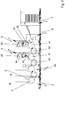
- the device for treating substrates 1 with a separating device 2, with which the processed substrate 1 can be separated into at least one waste part 9 and at least one use 10, can be designed as an independent machine and in this case has a feed system for substrate 1, which is not described in detail .
- the separating device 2 is part of a substrate-processing machine, in particular a sheet-processing machine, and is operated inline with the units of the sheet-processing machine.
- a sheet-fed printing machine is provided as the sheet-processing machine, as is shown in, for example Fig. 1 is shown.
- the sheet-fed printing machine includes a feed system for substrates 1, also referred to as feeder 7.
- Substrates 1 are understood to be, in particular, sheet-shaped workpieces made of paper, cardboard, cardboard, corrugated cardboard, plastic or the like, which are preferably printable or printed.
- the substrates 1 are present in the feeder 7 of the sheet-fed printing machine as a stack and are separated by this and fed to the units of the sheet-fed printing machine downstream of the feeder 7 via an acceleration system 8.
- the sheet-fed printing machine comprises at least one, preferably several, printing units 6.
- the printing units 6 each include, in particular, a printing cylinder 41 and a sheet-guiding cylinder 42, preferably designed as a transfer drum 42.
- the printing cylinder 41 is assigned a blanket cylinder 43 carrying a blanket and a plate cylinder 44 carrying a printing plate.
- the plate cylinder 44 is in contact with an inking unit 45 and preferably also a dampening unit.
- the substrate sheet 1 is guided in a known manner by the sheet holding systems provided on the printing cylinder 41 and sheet guide cylinder 42, printed in the nip formed between the printing cylinder 41 and blanket cylinder 43 and to the subsequent unit of the sheet-fed printing machine, e.g. in the form of the next printing unit 6, passed.
- the processing units 46 preferably comprise two processing cylinders 96, 97, one of which, preferably the lower one, has a sheet holding system and the other, preferably the upper one, has a tool carrier.
- the sheet holding system of the processing cylinder 96 can be designed as a clamping gripper system or as a suction gripper system. In its function and it is preferably identical to the gripper system (clamping gripper system or suction gripper system) of the transport cylinder 3, reference is made to the description thereof.
- the processing cylinders are assigned to one another with the formation of a cylinder gap. At least one of the processing cylinders carries a tool.
- a pair of processing cylinders is formed by the printing cylinder 41 and blanket cylinder 43 of a printing unit 6.
- a printing unit 6 serves as the processing unit 46.
- the clamping device for the rubber blanket is used to fasten the tool on the rubber blanket cylinder 43.
- the processing cylinders can be designed in a variety of ways.
- the upper processing cylinder is designed as a full magnetic cylinder or carrier cylinder with magnetic segments for holding magnetic sheets or magnetic sheets and the lower processing cylinder as a surface-hardened cylinder or with a hardened sheet attached to it.
- the upper processing cylinder is a full magnetic cylinder or carrier cylinder with magnetic segments for holding magnetic sheets or magnetic sheets and the lower processing cylinder is a surface-hardened cylinder or with a hardened sheet attached to it or formed with a sheet of hard rubber / plastic.
- the lower processing cylinder can be provided with tool carriers or elevator carriers that act mechanically, in particular positively or non-positively, in all of the above-mentioned cases.
- the force-fit tool carriers or elevator carriers are designed in particular to act magnetically.
- the device for treating substrates 1, which can be designed as a sheet processing machine or can be part of the same, in particular a processing unit 46, comprises a first and a second processing cylinder 96, 97. Between the first and a second processing cylinder 96, 97 are substrate sheets 1 which can be introduced at
- the first processing cylinder 96 has a sheet holding system.
- the first and / or the second machining cylinder 96, 97 have a tool carrier for receiving a tool or a tool part, which preferably comes from the group of cutting tools, punching tools, creasing tools, perforating tools or grooving tools.
- a counter-cylinder 98 is assigned to the second processing cylinder 97 on its side facing away from the first processing cylinder 96 and is in surface contact with the second processing cylinder 97.
- the counter cylinder 98 is assigned to the processing cylinder 97 in such a way that when the processing cylinder 97 bends, as occurs when processing substrate sheet 1 in the gap between the two processing cylinders 96, 97, the force of the resulting bending force of the second processing cylinder 97 pushes the counter cylinder 98, preferably in its center or near its center.
- the centers of the first and second processing cylinders 96, 97 and of the counter cylinder 98 preferably lie on an imaginary straight line or the centers of the second processing cylinder 97 and the counter cylinder 98 lie on a straight line that is opposite to a straight line on which the center points of the first and the second processing cylinder 96, 97 are inclined by an angle less than or equal to 10 degrees.
- the counter cylinder 98 can have the same diameter as the second processing cylinder 97.
- the counter cylinder 98 and the second machining cylinder 97 can also have bearer rings which are in rolling contact with one another. It is also possible that the surface contact between the counter cylinder 98 and the second machining cylinder 97 is limited to the contact between the bearer rings. In this case, at least one bending of the second processing cylinder 97 is counteracted in each case in the areas between its bearing points in a frame wall and the bearer ring adjacent to the respective bearing point.
- bearer rings are known in printing machine construction. Bearer rings on printing machines are placed on the sides of the printing cylinders.
- the Schmitz ring is supposed to prevent Schmitz. It is made of tempered steel and is ground with high precision, round and true to size.
- the bearer ring is approx. 1-4 cm wide and rolls either on the foundation rail or on the bearer ring of the counter cylinder.
- the circumference of the bearer ring is exactly the circumference of the elevator or it has exactly the circumference of the shape, depending on which machine part it is attached to.
- the bearer ring is an element of the positive control on printing machines with a central drive and compensates for minor bearing inaccuracies as well as uneven input and output from the gear drive of the printing machines.
- a device for adjusting the pressure between the bearer rings by displacing the counter cylinder 98 and / or the second machining cylinder 97 is advantageously provided.
- a device for fixing an elevator is preferably assigned to the counter cylinder 98. This enables an elevator to be arranged on the counter-cylinder 98 to ensure that it is in surface contact, in particular rolling contact, with the machining cylinder 97 or with the tool arranged on its surface, even when the tool is arranged on the second machining cylinder 97, the thickness of which can vary .
- a device for tensioning the elevator in the circumferential direction of the opposing cylinder 98 is preferably also assigned to the counter-cylinder 98, which device can form a structural unit with the device for fixing an elevator.
- the opposing cylinder 98 has a register system for positioning a elevator on the opposing cylinder 98.
- the device for treating substrates 1 comprises a processing unit 46 with two processing cylinders which interact with one another 96, 97, between which the substrate 1 can be inserted.
- the substrate 1 is processed as it passes through tool parts from the group of cutting tools, punching tools, creasing tools, perforating tools or grooving tools that are effective in the cylinder gap between the processing cylinders 96, 97.
- At least one of the processing cylinders 96, 97 is designed as a magnetic cylinder.
- a peeling device for peeling off at least one tool part is assigned to the machining cylinder 96, 97 designed as a magnetic cylinder.
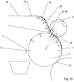
- the device for treating substrates 1 comprises a separating device with a transport cylinder 3 and a break-out cylinder 4, between which the substrate 1 can be inserted. As the substrate 1 passes through the cylinder gap between the transport cylinder 3 and the stripping cylinder 4, it is separated into at least one waste part 9 and at least one use 10 by at least one elevator 5.
- the transport cylinder 3 and / or the break-out cylinder 4 are designed as magnetic cylinders.
- a peeling device 103 for peeling off the at least one elevator 5 is assigned to the transport cylinder 3 and / or the stripping cylinder 4. See in particular Figure 47 and 48 .
- the peeling device 103 is designed to be adjustable and / or adjustable on the cylinder to which it is assigned and which is designed to carry an elevator 5, in particular to the processing cylinder 96, 97 or the transport cylinder 3 or the stripping cylinder 4.
- the peeling device 103 has a peeling edge 104.
- the peeling edge 104 extends when the peeling device 103 is positioned against the respective cylinder, preferably tangentially or approximately tangentially to the periphery of the cylinder to which it is assigned, i.e. in particular to the processing cylinder 96, 97, transport cylinder 3 or stripping cylinder 4. It also proves It is advantageous if the peeling device 103 forms a structural unit with a protection 70, 71.
- the protection 70, 71 can, for example, be any part of the housing of a processing unit 46 or a separating unit 2.2 that the operator is in front of
- the peeling device 103 preferably has a holding element for fixing the tool parts or the at least one elevator 5.
- the holding element can act pneumatically or magnetically or be designed in another suitable manner, for example in the form of a step or pawl.
- an ejector is designed for this purpose, which is assigned to the processing cylinder 96, 97 and / or the transport cylinder 3 and / or the break-out cylinder 4 and which is used to at least partially lift tool parts or the at least one elevator 5 from the surface of the Processing cylinder 96, 97 or the transport cylinder 3 or the break-out cylinder 4 is formed.
- a drive acting on the processing cylinder 96, 97 and / or the transport cylinder 3 and / or the break-out cylinder 4 is preferably formed, with which a drive control interacts.
- the drive control causes the processing cylinder 96, 97 and / or the transport cylinder 3 and / or the stripping cylinder 4 to be automatically positioned in a position in which one end of a tool part or of the at least one elevator 5 is opposite the peeling device 103 and / or in The effective area of the peeling device 103, in particular the peeling edge 104, is located.
- the drive control can cause the processing cylinder 96, 97 and / or the transport cylinder 3 and / or the break-out cylinder 4 to rotate in such a way that the other end of the tool part or of the at least one elevator 5 is opposite the peeling device 103 and / or is located in the effective area of the peeling device 103.
- the peeling device 103 peels the tool part or the at least one elevator 5 from the respective cylinder surface.
- the ejector is used to at least partially lift the respective tool part or the at least one elevator 5 from the surface of the processing cylinder 96, 97 or the transport cylinder 3 or the break-out cylinder 4 is preferably activated.
- a magnetic cylinder is to be understood as meaning all types of cylinders or drums which, in the area of their periphery, exert a magnetic force on neighboring ferromagnetic elements, in particular on tools or tool parts from the group of cutting tools, punching tools, creasing tools, perforating tools or grooving tools.
- Such a cylinder can be designed as a full magnetic cylinder or cylinder with embedded magnet segments or as a carrier cylinder for magnet segments or magnetic sheets arranged on it, which applies to the design as a drum in the analogous sense.
- the device for treating substrates 1, which can be designed as a sheet processing machine or can be part of the same, in addition to plants preferably designed as printing units 6 and processing units 46, also further units which are arranged individually or in groups in any order could be.
- One or more coating units 88.2 and / or one or more separating units 2.2 and / or one or more window applicator units 85 or a film applicator unit 85 and / or one or more punching units can be arranged in alternative or in addition to the aforementioned units.
- a separating mechanism 2.2 preferably includes a transport cylinder 3 with it
- a break-out cylinder 4 is preferably assigned to the transport cylinder 3.
- a coating unit 88.2 preferably comprises a device for sheet transport, in particular a sheet-guiding cylinder and a coating device 88 and is designed for partially or full-surface coating of a substrate sheet 1 with an adhesive having an adhesive effect.
- a window applicator 85 or film applicator 85 can be designed in various designs.
- the film is in the form of film sections.
- the first design preferably comprises a transport cylinder 3.1 for transporting sheet-shaped substrates 1, a sheet conveying device, e.g. in the form of a sheet-guiding cylinder, which interacts with the transport cylinder 3.1, a film feed 86, which has means for guiding film sections, a coating device 88 for feeding an adhesion promoter to the substrate 1 or to a respective film section.
- the film feed 86 can have a memory 93 for receiving a stack formed from film sections and a separating device which separates film sections from the stack formed from film sections and accelerates them to the circumferential speed of the transport cylinder 3.1.
- the film feed 86 preferably comprises a feed cylinder 84 which forms a press nip with the transport cylinder 3.1.
- the separating device can have a transport member 94 for separating the film sections from the top or from the bottom of the stack formed from film sections.
- a transport member 94 is preferably formed.
- the transport member 94 can have one or more elements from the group of suction belts and / or suction rollers and / or suction devices.
- the transport mechanism is used Elements preferably a force effect as a result of an applied negative pressure.
- a suction device is provided as the transport element 94, it can be designed, for example, as a combined suction device and have one or more tow suction devices that interact with one or more lifting suction devices.
- the transport member 94 can be provided for the direct feeding of a respective separated film section to the press nip or feed cylinder 84.
- direct feed is to be understood as the feed without transfer, ie intermediate transfer to another transport element 94.
- openings are preferably formed which can be supplied with suction air by air supply means.
- the air supply means for the suction air supply can be designed as a function of the angular position of the openings supplied in each case.
- the coating device 88 can be assigned to the transport cylinder 3.1 or a feed cylinder 84. If the coating device 88 is assigned to the transport cylinder 3.1, the substrate 1 is coated directly and then brought into contact with a section of film. If the coating device 88 is assigned to the feed cylinder 84, the substrate 1 is coated indirectly. This means that the adhesion promoter, in particular the adhesive, is fed to a respective film section which is then brought into contact with a substrate sheet 1.
- the coating device 88 can be designed in the manner of a coating unit and / or comprise an application roller and / or an inkjet head.
- the coating device 88 is preferably designed in such a way that it enables an addressable, partial coating of the respective substrate sheet 1 or the respective film section with adhesion promoter, in particular adhesive.
- a printing form in particular a lacquer plate, in particular a flexographic plate, can be provided for the addressable, partial coating.
- the film is in the form of a film web 87.
- the second design preferably comprises a transport cylinder 3.1 for transporting sheet-shaped substrates 1, a sheet conveying device which interacts with the transport cylinder 3.1, a film feed 86 which has means for guiding a film web 87.
- a coating device 88 for feeding an adhesion promoter to the substrate 1 and a cutting device 89 for cutting the film web 87 into film sections or for severing film sections from the film web 87 are preferably assigned to the second design.
- the film feed 86 preferably comprises means for guiding the film sections.
- the film feed 86 preferably comprises a feed cylinder 84 which forms a press nip with the transport cylinder 3.1.
- the cutting device 89 can be assigned to the feed cylinder 84. According to one embodiment of the cutting device 89, it comprises a cutting cylinder 90 which has a cutting means or separating means which is effective in the gap between the feed cylinder 84 and the cutting cylinder 90.
- the cutting means can be designed as a cross cutter or in another suitable form.
- openings are preferably formed which can be supplied with suction air by air supply means. According to one embodiment, the air supply means for the suction air supply can be designed as a function of the angular position of the openings supplied in each case.
- the coating device 88 can be assigned to the transport cylinder 3.1 or a feed cylinder 84. If the coating device 88 is assigned to the transport cylinder 3.1, the substrate 1 is coated directly and then brought into contact with a section of film. If the coating device 88 is assigned to the feed cylinder 84, the substrate 1 is coated indirectly. This means that the adhesion promoter, in particular the adhesive, is fed to a respective film section which is then brought into contact with a substrate sheet 1.
- the coating device 88 can be designed in the manner of a coating unit and / or comprise an application roller and / or an inkjet head.
- the coating device 88 is preferably designed in such a way that it enables an addressable, partial coating of the respective substrate sheet 1 or the respective film section with adhesion promoter, in particular adhesive.
- a printing form in particular a lacquer plate, in particular a flexographic plate, can be provided for the addressable, partial coating.
- the film feed 86 comprises an unwinding device 91 which is designed to receive one or more film rolls 92.
- the unwinding device 91 preferably has positioning means for receiving a plurality of film rolls 92, the film rolls 92 being able to be positioned axially and / or radially in relation to one another with the positioning means.
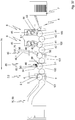
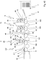
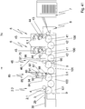
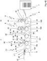
- a window applicator 85 or film applicator 85 of the second design is, for example, in FIG Figure 33 or 40 shown.
- the film feed 86 of this window applicator 85 or film applicator 85 comprises an unwinding device 91 and a winding device.
- a cutting device 89 can also be provided, is shown in FIG Figure 33 or 40 but not shown.
- a coating device 88 is assigned to the feed cylinder 84.
- Another window applicator 85 or film applicator 85 of the second design is Figure 34 or 41 it can be seen that it differs from the window applicator 85 or film applicator 85 according to FIG Figure. 33 or 40 in that the coating device 88 is assigned to the transport cylinder 3.1.
- Another window applicator 85 or film applicator 85 of the second design is Figure 35 or 42 refer to.
- the film feed 86 is an unwinding device 91 but not a winding device. includes.
- the A cutting device 89 with a cutting cylinder 90 is assigned to the feed cylinder 84.
- Another window applicator 85 or film applicator 85 of the second design is Figure 36 or 43 refer to. It has a film feed 86 with an unwinding device 91.
- a cutting device 89 with a cutting cylinder 90 is assigned to the transport cylinder 3.1.
- the coating device 88 is assigned to the transport cylinder 3.1.
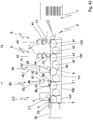
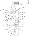
- a window applicator 85 or film applicator 85 of the first design shows, for example Figure 37 or 44 .
- the film feed 86 comprises a store 93 for receiving a stack formed from film sections and at least one transport element 94.
- the transport element 94 feeds a respective film section to the transport cylinder 3.1.
- the coating device is assigned to the transport cylinder 3.1.
- the device for treating substrates 1 which can be designed as a sheet processing machine or can be part of the same, comprises a feeder 7 to which one or more printing units 6 and / or one or more punching units are connected a separating unit 2.2 is connected, to which either a coating unit 88.2 and a film application unit or window application unit 85 or a window application unit 85 having a coating device 88 adjoin.
- a device or sheet processing machine is particularly suitable for producing film windows. Embodiments of such machines are in particular the Figures 33 to 46 removable.
- the film applicator or window applicator 85 is followed by a separating unit 2.2.
- the film applicator or window applicator 85 or the last separating unit 2.2 in the transport direction 74) of the substrate 1 is preferably followed by a delivery 99.
- the device for treating substrates 1 which can be designed as a sheet processing machine, comprises a feeder 7 and one or more first substructure modules 100, each of which has a printing cylinder 41 with means for fixing an elevator and a sheet conveying device and one or more a plurality of second substructure modules 101, each of which has a transport cylinder 3 with openings 12 formed in its outer surface as well as means for fixing an elevator 5 and a sheet conveyor device.
- All first and second substructure modules 100, 101 preferably have the same interfaces on the input side and / or output side for connecting the substructure modules 100, 101 to one another in a freely specifiable sequence and can be equipped or equipped with an add-on module.
- Air supply means 14 can be formed to supply the openings 12 with air.
- the pressure cylinder 41 of at least one first substructure module 100 is preferably designed as a magnetic cylinder. All pressure cylinders 41 of the first substructure modules 100 are preferably designed as magnetic cylinders. Likewise, all substructure modules 100, 101 can have structurally identical sheet conveying devices.
- first substructure modules 100 are preferably for equipping with an attachment module designed as a printing module 6.1 or as a lacquer module or as a drying module or as a film application module 85.1 or as a processing module 46.1 and / or all second substructure modules 101 for equipping with a separating module 2.1 or a Inspection module trained add-on module. More preferably, all of the first substructure modules 100 and / or all of the second substructure modules 101 have structurally identical interfaces for connection to add-on modules.
- the separating module 2.1 preferably comprises a break-out cylinder 4.
- the adhesive module 88.1 comprises at least one device for applying adhesive.
- the processing module 46.1 preferably comprises a punching cylinder 75 or a cylinder prepared for receiving a punching form.
- the printing module 6.1 preferably comprises a plate cylinder 44, a rubber blanket cylinder 43 and an inking unit 45.
- the film application module 85.1 preferably comprises a device for feeding in film sections.
- the feeder 7 is followed by at least one first substructure module 100 equipped with a printing module 6.1 or a processing module 46.1, and at least one second substructure module 101 equipped with a separating module 2.1.
- the feeder 7 can also be followed by one or more first substructure modules 100 equipped with a printing module 6.1, followed by one or more first substructure modules 100 equipped with a processing module 46.1, followed by a second substructure module 101 that is equipped with a separating module 2.1, followed by a first or second substructure module 100, 101 that is equipped with a film application module 85.1.
- a substructure module 102 equipped with an adhesive module 88.1 is arranged between the substructure module 100 equipped with a separating module 2.1 and the substructure module 100 equipped with an adhesive module 88.1, or the foil application module 85.1 comprises a device for adhesive application.
- the following structural units are formed in connection with one another: feeder 7, acceleration system 8, several printing units 6, processing unit 46, film applicator or window applicator 85, separating unit 2.2 and delivery 99.
- the mode of operation is as follows.
- the substrate sheets 1 separated by the feeder 7 are accelerated by the acceleration system 8 and printed in the printing units 6.
- the punching of window-shaped recesses in the substrates 1 then takes place in the processing unit 46, the waste parts 9 then being removed.
- film applicator or window applicator 85 film sections are coated with adhesive and fixed in an overlapping manner on the window-shaped recesses.
- the subsequent separation plant 2.2 further waste parts 9 are broken out and the substrate sheets 1 are placed in a stack in the display 99.
- the following structural units are formed in connection with one another: feeder 7, acceleration system 8, several printing units 6, processing unit 46, film applicator or window applicator 85, separating unit 2.2 and delivery 99.
- the mode of operation is as follows.
- the substrate sheets 1 separated by the feeder 7 are accelerated by the acceleration system 8 and printed in the printing units 6.
- the punching of window-shaped recesses in the substrates 1 then takes place in the processing unit 46, the waste parts 9 then being removed.
- the film applicator or window applicator 85 the substrate sheets 1 are coated with adhesive and the film sections are fixed in an overlapping manner on the window-shaped recesses.
- further waste parts 9 are broken out and the substrate sheets 1 are placed in a stack in the display 99.
- the following units are formed in connection with one another: feeder 7, acceleration system 8, several printing units 6, Processing unit 46, film application unit or window application unit 85, separating unit 2.2 and delivery 99.
- the mode of operation is as follows.
- the substrate sheets 1 separated by the feeder 7 are accelerated by the acceleration system 8 and printed in the printing units 6.
- the punching of window-shaped recesses in the substrates 1 then takes place in the processing unit 46, the waste parts 9 then being removed.
- film applicator or window applicator 85 film sections are separated from the film web 87 by means of a cutting device 89 and a cutting cylinder 90 and then coated with adhesive and fixed in an overlapping manner on the window-shaped recesses.
- the subsequent separation plant 2.2 further waste parts 9 are broken out and the substrate sheets 1 are placed in a stack in the display 99.
- the following structural units are formed in connection with one another: feeder 7, acceleration system 8, several printing units 6, processing unit 46, film applicator or window applicator 85, separating unit 2.2 and delivery 99.
- the mode of operation is as follows.
- the substrate sheets 1 separated by the feeder 7 are accelerated by the acceleration system 8 and printed in the printing units 6.
- the punching of window-shaped recesses in the substrates 1 then takes place in the processing unit 46, the waste parts 9 then being removed.
- the film applicator or window applicator 85 the substrate sheets 1 are coated with adhesive and the film sections are separated from the film web 87 by means of a cutting device 89 and a cutting cylinder 90 and then fixed in an overlapping manner on the window-shaped recesses.
- further waste parts 9 are broken out and the substrate sheets 1 are placed in a stack in the display 99.
- the following structural units are formed in connection with one another: feeder 7, acceleration system 8, several printing units 6, processing unit 46, film applicator or window applicator 85, separating unit 2.2 and Display 99.
- the mode of operation is as follows.
- the substrate sheets 1 separated by the feeder 7 are accelerated by the acceleration system 8 and printed in the printing units 6.
- the punching of window-shaped recesses in the substrates 1 then takes place in the processing unit 46, the waste parts 9 then being removed.
- the film applicator or window applicator 85 the substrate sheets 1 are coated with adhesive and the film sections are fed from a storage 93 via a transport element 94 to the transport cylinder 3.1 and fixed in an overlapping manner on the window-shaped recesses.
- the subsequent separation plant 2.2 further waste parts 9 are broken out and the substrate sheets 1 are placed in a stack in the display 99.
- the following units are formed in connection with one another: feeder 7, acceleration system 8, several printing units 6, processing unit 46, coating unit 88.2, film applicator unit or window applicator unit 85, separating unit 2.2 and delivery 99.
- the mode of operation is as follows.
- the substrate sheets 1 separated by the feeder 7 are accelerated by the acceleration system 8 and printed in the printing units 6.
- the punching of window-shaped recesses in the substrates 1 then takes place in the processing unit 46, the waste parts 9 then being removed.
- the coating unit 88.2 the substrate sheets 1 are coated with adhesive.
- film applicator or window applicator 85 film sections are fixed in an overlapping manner on the window-shaped recesses.
- the subsequent separation plant 2.2. further waste parts 9 are broken out and the substrate sheets 1 are placed in a stack in the display 99.
- the following structural units are formed in connection with one another: feeder 7, acceleration system 8, several printing units 6, processing unit 46, separating unit 2.2, film applicator or window applicator 85, separating unit 2.2 and delivery 99.
- the mode of operation is as follows.
- the 7 Individual substrate sheets 1 are accelerated by the acceleration system 8 and printed in the printing units 6.
- the punching of window-shaped recesses in the substrates 1 then takes place in the processing unit 46, the waste parts 9 then being removed.
- separating unit 2.2 further waste parts 9 are broken out.
- film applicator or window applicator 85 film sections are coated with adhesive and fixed in an overlapping manner on the window-shaped recesses.
- further waste parts 9 are broken out and the substrate sheets 1 are placed in a stack in the display 99.
- Fig. 40 the following structural units are formed in connection with one another: feeder 7, acceleration system 8, several printing units 6, processing unit 46, film applicator or window applicator 85, separating unit 2.2 and conveyor belts 29, 30.
- the mode of operation is as follows.
- the substrate sheets 1 separated by the feeder 7 are accelerated by the acceleration system 8 and printed in the printing units 6.
- the punching of window-shaped recesses in the substrates 1 then takes place in the processing unit 46, the waste parts 9 then being removed.
- film applicator or window applicator 85 film sections are coated with adhesive and fixed in an overlapping manner on the window-shaped recesses.
- the subsequent separation plant 2.2 either only further waste parts 9 or waste parts 9 are broken out together with the frame and removed.
- the conveyor belts 29, 30 transport substrate sheets 1 or broken copies 10 to a stack in accordance with the previous separation process.
- the following structural units are formed in connection with one another: feeder 7, acceleration system 8, several printing units 6, processing unit 46, film applicator or window applicator 85, separating unit 2.2 and conveyor belts 29, 30.
- the mode of operation is as follows.
- the substrate sheets 1 separated by the feeder 7 are accelerated by the acceleration system 8 and printed in the printing units 6.
- the punching then takes place in the processing unit 46 window-shaped recesses in the substrates 1, the waste parts 9 then being removed.
- the film applicator or window applicator 85 the substrate sheets 1 are coated with adhesive and the film sections are fixed in an overlapping manner on the window-shaped recesses.
- the subsequent separation plant 2.2 either only further waste parts 9 or waste parts 9 are broken out together with the frame and removed.
- the conveyor belts 29, 30 transport substrate sheets 1 or broken copies 10 to a stack in accordance with the previous separation process.
- the following structural units are formed in connection with one another: feeder 7, acceleration system 8, several printing units 6, processing unit 46, film applicator or window applicator 85, separating unit 2.2 and conveyor belts 29, 30.
- the mode of operation is as follows.
- the substrate sheets 1 separated by the feeder 7 are accelerated by the acceleration system 8 and printed in the printing units 6.
- the punching of window-shaped recesses in the substrates 1 then takes place in the processing unit 46, the waste parts 9 then being removed.
- film applicator or window applicator 85 film sections are separated from the film web 87 by means of a cutting device 89 and a cutting cylinder 90 and then coated with adhesive and fixed in an overlapping manner on the window-shaped recesses.
- the subsequent separation plant 2.2 either only further waste parts 9 or waste parts 9 are broken out together with the frame and removed.
- the conveyor belts 29, 30 transport substrate sheets 1 or broken copies 10 to a stack in accordance with the previous separation process.
- the following structural units are formed in connection with one another: feeder 7, acceleration system 8, several printing units 6, processing unit 46, film applicator or window applicator 85, separating unit 2.2 and Conveyor belts 29, 30.
- the mode of operation is as follows.
- the substrate sheets 1 separated by the feeder 7 are accelerated by the acceleration system 8 and printed in the printing units 6.
- the punching of window-shaped recesses in the substrates 1 then takes place in the processing unit 46, the waste parts 9 then being removed.
- the film applicator or window applicator 85 the substrate sheets 1 are coated with adhesive and the film sections are separated from the film web 87 by means of a cutting device 89 and a cutting cylinder 90 and then fixed in an overlapping manner on the window-shaped recesses. either only further waste parts 9 or waste parts 9 are broken out together with the frame and removed.
- the conveyor belts 29, 30 transport substrate sheets 1 or broken copies 10 to a stack in accordance with the previous separation process.
- the following structural units are formed in connection with one another: feeder 7, acceleration system 8, several printing units 6, processing unit 46, film applicator or window applicator 85, separating unit 2.2 and conveyor belts 29, 30.
- the mode of operation is as follows.
- the substrate sheets 1 separated by the feeder 7 are accelerated by the acceleration system 8 and printed in the printing units 6.
- the punching of window-shaped recesses in the substrates 1 then takes place in the processing unit 46, the waste parts 9 then being removed.
- the film applicator or window applicator 85 the substrate sheets 1 are coated with adhesive and the film sections are fed from a storage 93 via a transport element 94 to the transport cylinder 3.1 and fixed in an overlapping manner on the window-shaped recesses.
- the subsequent separation plant 2.2 either only further waste parts 9 or waste parts 9 are broken out together with the frame and removed.
- the conveyor belts 29, 30 transport substrate sheets 1 or broken copies 10 to a stack in accordance with the previous separation process.
- the following units are formed in connection with one another: feeder 7, acceleration system 8, several printing units 6, processing unit 46, coating unit 88.2, film applicator unit or window applicator unit 85, separating unit 2.2 and conveyor belts 29, 30.
- the mode of operation is as follows.
- the substrate sheets 1 separated by the feeder 7 are accelerated by the acceleration system 8 and printed in the printing units 6.
- the punching of window-shaped recesses in the substrates 1 then takes place in the processing unit 46, the waste parts 9 then being removed.
- the coating unit 88.2 the substrate sheets 1 are coated with adhesive.
- film applicator or window applicator 85 film sections are fixed in an overlapping manner on the window-shaped recesses.
- the subsequent separation plant 2.2 either only further waste parts 9 or waste parts 9 are broken out together with the frame and removed.
- the conveyor belts 29, 30 transport substrate sheets 1 or broken copies 10 to a stack in accordance with the previous separation process.
- Fig. 46 the following units are formed in connection with one another: feeder 7, acceleration system 8, several printing units 6, processing unit 46, separating unit 2.2, film applicator or window applicator 85, separating unit 2.2 and conveyor belts 29, 30.
- the mode of operation is as follows.
- the substrate sheets 1 separated by the feeder 7 are accelerated by the acceleration system 8 and printed in the printing units 6.
- the punching of window-shaped recesses in the substrates 1 then takes place in the processing unit 46, the waste parts 9 then being removed.
- separating unit 2.2 further waste parts 9 are broken out.
- film applicator or window applicator 85 film sections are coated with adhesive and fixed in an overlapping manner on the window-shaped recesses.
- the subsequent separation plant 2.2 In the subsequent separation plant 2.2.
- the procedure is as follows.
- a punching process step window-shaped areas are punched into the substrates 1, with material connections being retained.
- a cutting process step which preferably immediately follows the punching process step
- the window-shaped areas are broken out of the substrates 1, the material connections being severed so that window-shaped cutouts are formed in the substrates 1.
- a coating process step which preferably immediately follows the separating process step
- the substrates 1 are coated with adhesive in the adjoining area of the window-shaped recesses.
- film sections whose extension is greater than the extension of the window-shaped cutouts are positioned over the window-shaped cutouts and fixed with the adhesive.
- panels 10 are punched into the substrates 1, in each of which at least one window-shaped area is arranged, further material connections between the benefit 10 and between benefit 10 and waste parts 9 are retained.
- a panel 10 would represent an unfolded envelope.
- the substrates 1 are either placed directly on a stack or on a conveyor belt 29, 30; alternatively, the further material connections between the panels 10 or between the panels 10 and the waste parts 9, e.g. the outer frame, can be performed in a further separation process before being deposited , be severed. It is also possible to print the substrates 1 prior to the punching process step.
- the method steps described are preferably carried out in consecutive units of a sheet-processing machine, in particular a rotary printing press.
- a further embodiment relates to a method for treating sheet-shaped substrates 1.
- a respective substrate sheet 1 is separated from a stack formed from substrate sheet 1 by a feeder 7, then embossed and / or dried in a first processing unit 46, then grooved or punched and / or punched in a second processing unit 46, then in a third processing unit 46 punched and / or punched and / or perforated and / or embossed and / or grooved.
- the respective substrate sheet 1 is preferably printed in one or more printing units 6 and / or coated in one or more coating units between the separation in the feeder 7 and the treatment in the first processing unit 46.
- the printing and / or painting in at least one printing or painting unit can also take place between the treatment in two of the processing units 46 and / or after the treatment in the last processing unit 46.
- the sheet-shaped substrates 1 or panels 10 are preferably in one Display 99 or on a conveyor belt 29, 30 on a stack or as a result, shingled or not shingled, deposited.
- Cutting is understood to mean, in particular, the complete mechanical separation of an unpunched material by pressure, with predominantly shear stresses acting.
- the cutting process can be done with knife cut, shear cut, or burst cut.
- Punching is understood in particular to mean the dividing of materials in a dividing line deviating from the straight line.
- the production of cutouts and blanks with self-contained delimiting lines is considered.
- open cuts are also made by punching, e.g. B. rounding corners and register punching.
- Embossing is understood to mean the processing of materials by pressure with appropriate tools, the material being shaped and / or deformed in a relief-like manner.
- Grooves are understood to mean the processing of materials by means of pressure with appropriate tools, with elongated, narrow indentations being made in the surface of the material.
- Perforating is understood to mean the processing of materials by means of pressure with appropriate tools, with a large number of mostly linearly arranged holes being made in the material. The distances between the holes are preferably the same.
- a separate work is preferably provided in each case, which can be used in any Sequence can be combined with other plants to implement modified production processes.
- the works preferably have their own frame walls.
- the punching process step or the punching and cutting process steps are carried out with a punching unit, the cutting process step with a separating unit 2.2, the coating process step with a coating unit 88.2, the window application process step or the coating and window application process steps with a window applicator 85.
- either substrate sheets 1 (copies 10 connected to one another via residual webs with or without frames) are available after going through various processing stages, which are stored in a display 99 in stacks or punched-out copies 10, which are preferably conveyed out of the machine on a conveyor belt 30.
- These utility 10 are preferably divided into utility streams which are laterally spaced from one another.
- several pairs of bugs are arranged following the conveyor belt 30, with each pair of rollers diverging from the other pairs of rollers, ie being arranged with a different lateral angular position.
- the roller pairs each form a roller gap and rotate at a circumferential speed that is greater than the speed of the conveyor belt 30.
- the adjacent and one behind the other panels 10 are conveyed by the conveyor belt 30 into a respective roller gap.
- the respective benefits 10 are then detected in the roller gap, accelerated to the circumferential speed of the rollers and spaced from one another in accordance with the alignment of the roller pair.
- the roller pairs are for Positioning on the benefits 10 can be displaced transversely to their transport direction 74.
- a conveyor belt is arranged that picks up and transports away the items 10, which are now laterally spaced apart from one another.
- the downstream conveyor belt preferably runs at a speed that is lower than the peripheral speed of the roller pairs.
- a device for treating, in particular depositing, substrates 1, in particular panels 10, can be connected to the downstream conveyor belt, which is described below in particular with regard to the Figures 18 and 19th is described.
- the device comprises a circulating conveyor belt 29, 30, which conveys the substrates 1, in particular panels 10, in at least one path, preferably as an imbricated flow, against at least one stop 77 for depositing the substrates 1 on a stack carrier 78.
- the stack carrier 78 can be a commercially available pallet or a system pallet such as are used in logistics systems in printing works or in the area of further processing.
- a transport device 79 is designed with which the stack carrier 78 can be displaced under the at least one stop 77 and / or the conveyor belt 29, 30 in such a way that the substrate sheets 1 or panels conveyed by the conveyor belt 29 10 on the stacking carrier 78.
- the transport device 79 is designed for the vertical and horizontal displacement of the stack carrier 78.
- the conveyor belt 29, 30 is assigned a device for forming a gap in the imbricated stream 83, which is preferably designed as a roller 83 or roller.
- the roller 83 or roller is arranged to be displaceable, for which purpose it is preferably mounted on levers at the end.
- the roller 83 or roller is relocated or pivoted until it is in surface contact with the conveyor belt 29, 30. If the conveyor belt 29, 30 further conveys substrate sheets 1 as a result of its movement, these are accumulated on the roller 83 or roller.
- the roller 83 or roller can be mounted in a stationary or rotatable manner and in the latter case is preferably braked.
- the transport device 79 is designed to move the stack carrier 78 in one or more positions in which the stack carrier 78 and the at least one stop 77 and / or the stack carrier 78 and the conveyor belt 29, 30 overlap.
- a plurality of stops 77 are preferably arranged transversely to the transport direction 74 of the substrate sheet 1 or the benefit 10 on the conveyor belt 29, 30 in groups next to one another. More preferably, each group of stops 77 has either two side stops or two side stops and one back stop. In each case a group of stops preferably forms a type of pocket which is aligned on the conveyor belt 29, 30 by positioning the stops 77 laterally on the stream or streams of substrate sheet 1 or sheet 10.
- the stops 77 are designed to be vertically movable.
- the transport device 79 preferably has a drive which is designed for the discontinuous or continuous displacement of the stack carrier 78.
- the transport device 79 is preferably designed to move the stack carrier 78 in and against the transport direction 74 of the transport belt 29, 30. More preferably, the transport device 79 is designed to move the stack carrier 78 in the transport direction 74 of the transport belt 29, 30 depending on the extent of the substrates 1 or panels 10 in the transport direction 74 of the transport belt 29, 30.
- the transport device 79 is designed to implement a movement cycle that comprises a first and at least one further movement of the stack carrier 78 in the transport direction 74 of the conveyor belt 29, 30, the stack carrier 78 between its first and its at least one further movement in relation to the transport direction 74 of the conveyor belt 29, 30 is stationary.
- a feed device 80 can be formed with which at least one separating element 81 can be positioned on the substrates 1 carried by the stack carrier 78.
- the feed device 80 comprises a separating device which separates the separating elements 81 from a stack 82 formed from a plurality of separating elements 81.
- the separating elements 81 are preferably sheet-like materials that can be inserted between utility stacks for spatial separation of the same from one another.
- the feed device 80 can be formed by a horizontally displaceable frame, the underside of which is assigned vertically displaceable suction cups or other suitable fixing elements.
- the design of the feed device 80 with rigid suction cups or other suitable fixing elements is also possible, provided that the frame allows a vertical movement for lifting a respective separating element 81.
- Preferred sequences of movements that the stack carrier 78 realizes by the action of the transport direction 74 will be described below in particular with reference to the Figures 20 to 32 are described by way of example.
- the stack carrier 78 is positioned by the transport device 79 in relation to the transport belt 29, 30 in such a way that it is as small as possible from its underside in relation to its vertical position.
- the positioning takes place in such a way that copies 10 or substrate sheets 1 conveyed by the conveyor belt 29, 30 reach the deposit on the stack carrier 78.
- substrate sheets 1 or panels 10 are then conveyed onto the stack carrier 78 and, in the process, aligned laterally by the stops 77 and preferably also in the direction of transport 74.
- the stack of substrate sheet 1 or panel 10 grows, as in FIG Figure 21 shown.
- the stack carrier 78 is preferably lowered.
- the stops 77 can be lowered synchronously with the lowering movement of the stack carrier 78.
- the stack carrier 78 can also be positioned from the start at such a vertical distance from the conveyor belt 29, 30 that it can accommodate a sufficient amount of substrate sheet 1 or panels 10 without vertical movement.
- Figure 21 only one stack can be seen.
- several other adjacent stacks can be formed at the same time.
- the stops 77 if these have been displaced with the stack carrier 78, are again displaced vertically into their starting position.
- the stack carrier 78 is vertically in its starting position and displaced horizontally by a distance which corresponds to the length of the substrate sheets 1 to be deposited plus a distance value.
- the time sequence of the displacement of the stack carrier 78 and the stops 77 is irrelevant, provided collisions are avoided.
- the shift is preferably carried out synchronously.
- the device for forming a gap in the imbricated stream 83 is activated, so that during this time no substrate sheets 1 or panels 10 are fed to the stack carrier 78.
- the next stack of substrate sheets 1 or panels 10 can be formed on the stack carrier 78 ( Figure 24 ).
- the feed device 80 can be used. This grips the uppermost separating element 81 of the stack 82 formed from separating elements 81 and transports it over the stack of substrate sheet 1 or sheet 10 formed on the stack carrier 78, where it is released and is placed on the respective uppermost substrate sheet 1 or sheet 10 ( Figure 26 ). The surface of the separating sheet 81 takes the place of the surface of the stack carrier 78 in the further course and thus forms the new stack plane.
- a single or a series of stacks of substrate sheets 1 or panels 10 are formed on the new stack level.
- the stack carrier 78 is positioned in relation to its vertical position by the transport device 79 in such a way that the new stack plane lies below the release plane of the transport belt 29, 30. In relation to its horizontal position, the
- the stack carrier 78 can also be positioned from the start at such a vertical distance from the conveyor belt 29, 30 that it can accommodate a sufficient amount of substrate sheet 1 or panels 10 without vertical movement.
- the stops 77 if these have been displaced with the stack carrier 78, are again displaced vertically into their starting position.
- the stack carrier 78 is displaced vertically into the position it held at the beginning of the formation of the first stack on the separating element 81 and horizontally by a distance which corresponds to the length of the substrate sheets 1 to be deposited plus a distance value.
- the device for forming a gap in the imbricated stream 83 is activated, so that during this time no substrate sheets 1 or panels 10 are fed to the stack carrier 78.
- the next stack of substrate sheet 1 or use 10 can be formed on the separating element 81 ( Figure 31 ). If a sufficient number of stacks of substrate sheet 1 or panels 10 have been formed on the stack carrier 78, the loaded stack carrier 78 is transported away and replaced by a new stack carrier 78 capable of receiving it.
- One or more processing units 46 are preferably formed following one or more printing units 6. In the case of several printing units 6, these are mostly equipped with different tools from the group of cutting tools, punching tools, creasing tools, perforating tools or grooving tools. Likewise, one or more processing units 46 can precede one or more printing units 6. Alternatively, one or more processing units 46 are interposed between one or more printing units 6.
- the sheet-fed printing press preferably also comprises one or more coating units, which are preferably connected downstream of the printing units 6 or are connected to the processing units 46.
- a substrate-processing machine in particular a sheet-processing machine, which is not a printing machine, can have the same structure as the sheet-fed printing machine described, reduced by the printing units 6.
- the separating device 2 is formed following the printing units 6 or the processing units 46.
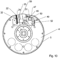
- the separating device comprises a transport cylinder 3.
- the transport cylinder 3 is twice the size, ie it transports two substrate sheets 1 per revolution.
- the invention is not limited to a double-size embodiment of the transport cylinder 3.
- the invention will now be described using a single-size system. This description is also representative of the double-size system or the multi-size system in analogous correspondence.
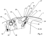
- a sheet holding system for fixing the front edges of the sheet-shaped substrate 1, in particular a gripper system is formed (in the case of a double-sized system, two sheet holding systems are formed).
- the gripper system is preferably designed as a suction gripper system 17, also referred to as a suction system 17, and is supplied by air supply means.
- the suction gripper system 17 is designed to generate a suction area, the extent of which in the axial direction of the transport cylinder 3 is a multiple of its extent in the circumferential direction.
- the extension of the suction area of the suction gripper system 17 in the circumferential direction of the transport cylinder 3 is preferably less than 20 mm, more preferably less than 15 mm, more preferably less than 10 mm.
- the suction area can be extended across the width of the Transport cylinder 3 extending opening or a plurality of adjacent suction openings be formed.
- the at least one suction opening is arranged for fixing the front edge of the substrate 1 in such a way that, when the elevator 5 is fixed, it is spaced apart from the elevator 5 in the circumferential direction of the transport cylinder 3.
- the extension of the suction area in the axial direction of the transport cylinder 3 is advantageously designed to be adjustable.
- adjustment means 28, in particular in the form of shut-off valves, can be provided in the supply path of the suction air for the suction openings which are outer with respect to the center of the transport cylinder 3.
- the adjustability of the extent of the suction area has the advantage that the consumption of suction air is minimized.
- the transport cylinder 3 also preferably has means (in the case of a double-sized system, two fixing means are formed) for fixing an exchangeable elevator 5.
- the means for fixing are preferably designed as clamping grippers. With them, a respective elevator 5 can be fixed on the rear edge and on the front edge.
- the means for fixing the front edge of the elevator 5 are preferably formed by the clamping element front edge 22 (also referred to as a clamping jaw) and the additional clamping element 24 (also referred to as a cuff) which interacts with this to form a clamping gap.
- the further clamping element 24 is fixedly mounted on the base body of the transport cylinder 3.
- the clamping element 22 is firmly connected to a lever 21 which is mounted on the base body of the transport cylinder 3 such that it can pivot about a pivot point 34.
- the lever 21 is tensioned by an energy store 23, which is preferably designed as a spring, in such a way that the clamping gap formed between the clamping element 22 and the further clamping element 24 closes.
- the spring 23 is designed as a compression spring and is supported with one end on the lever 21 and with its other end on the head of a screw screwed into the base body of the transport cylinder 3.
- the Figure 3 shows the clamping gripper front edge with the front edge of the elevator 5 fixed, ie in the closed state.
- the Figure 4 shows the clamping gripper front edge with the front edge of the elevator 5 released, ie in the open state.
- the front edge of the clamping gripper is opened against the force of the spring 23.
- the one to open the clamping gripper The force required at the front edge is preferably applied by an adjusting element 23, which can in particular be designed as a pneumatic muscle 23.
- the adjusting element or the pneumatic muscle 23 preferably acts on a further lever 33, one end of which is supported on a fixed point of the transport cylinder 3. Under the force of the actuating element 23, which can in particular be designed as a pneumatic muscle 23, the further lever 33 can be pivoted about the aforementioned fixed point. If it is designed as a pneumatic muscle 23, compressed air is applied to it, under the action of which it expands, the further lever 33 being pivoted. The pivoting movement of the further lever 33 is limited by a wall formed on the transport cylinder 3.
- the further lever 33 acts on a ball 35 which is formed between the further lever 33 and the lever 21 and displaces it. With the displacement of the ball 35, the lever 21 and with it the front edge 22 of the clamping element are also displaced.
- the force of the energy accumulator 23, in particular the spring 23, shifts the lever 21, the ball 35 and the further lever 33 in their direction Starting position until the movement is limited by striking the front edge 22 of the clamp element against the front edge 24 of the clamp element or the elevator 5.
- the rear edge of the elevator 5 can be fixed between a clamping element rear edge 47 and a further clamping element rear edge 48, which together form a further clamping gap.
- the force required to close the rear edge clamping gripper is applied by a rotatable tensioning shaft 50 which acts on the rear edge 47 clamping element via a toggle lever 51.
- At least one of the clamping grippers that is, the clamping gripper front edge or the clamping gripper rear edge, can be displaced in the circumferential direction of the transport cylinder.
- the rear edge of the clamping gripper can be moved.
- the rear edge of the clamping gripper is mounted on a slide that is displaceable in the circumferential direction of the transport cylinder 3.
- the carriage 49 also carries the tensioning shaft 50 and the Toggle lever 51. To tension the elevator 5, it is first fixed at both ends by the front edge of the clamping gripper and the rear edge by the clamping gripper.
- the slide 49 is then shifted clockwise, which is effected by a further adjusting element 52, which can also be designed as a pneumatic muscle.
- these preferably carry positioning pins or are preferably assigned positioning elements.
- the positioning pins or positioning elements can in particular be assigned directly to the further clamping element front edge 22.
- the transport cylinder 3 preferably has first and second openings 12, 13 which, when the elevator 5 is fixed, are at least partially covered by the openings that can be formed in the elevator 5.
- the openings 12, 13 are connected to air supply means 14, 15.
- first air supply means 14 are provided for supplying the first openings 12 with air
- second air supply means 15 are provided for supplying the second openings 13 with air.
- air is understood to mean all forms of system air, ie in particular blown air or suction air, which are particularly suitable for exerting physical effects such as force and which can be characterized by at least one of the parameters static pressure, dynamic pressure or volume flow. In particular, it does not depend on the chemical composition of the air or its moisture content.
- air is generated in a manner known per se with compressors, compressors, vacuum pumps, suction pumps or similar components.
- the aforementioned air generators can comprise the first and second air supply means 14, 15 of the transport cylinder and in particular form the air supply means 14, 15 together with all means that supply the air to the openings 12, 14 and / or control the supply.
- the first and second openings 12, 13 can preferably be supplied with air independently of one another.
- the air supply to either the first or the second openings 14, 15 or both openings 14, 15 is preferably designed to be switchable.
- switchability is, in particular, switching meant between suction air and blown air, whereby it does not matter which type of air supply is switched to which type.
- the first and the second openings 12, 13 are formed in the lateral surface of the transport cylinder 3.
- the first and second openings 12, 13 are preferably arranged alternately in the circumferential direction of the transport cylinder 3 or in the axial direction of the transport cylinder 3.
- the first and / or the second openings 12, 13 are preferably designed in the form of grooves or holes.
- the arrangement of the first and second openings 12, 13 in the outer surface of the transport cylinder 3 preferably results in a fine-meshed network of elements with which any openings formed in the elevator 5 can be supplied with air.
- the arrangement of the openings in the elevator 5 takes place in accordance with the arrangement of waste part or waste parts 9 on the one hand and benefit 10 on the other hand.
- perforations can be formed in the elevator 5, while none of the second openings 13 that are formed in the area of panels 10 are opposed by any perforations in the elevator 5.
- the air supply means 14, 15 for supplying the first and second openings 12, 13 preferably comprise one or more rotary slide valves or rotary inlets.
- the rotary slides or rotary inlets are preferably formed on the end face of the transport cylinder 3 or assigned to it.
- two rotary slides or two rotary inlets are formed on opposite end faces of the transport cylinder 3.
- the one in the Figures 5 , 6th and 7th includes the rotary valve or the at least a rotary lead-in a disk 18 which is assigned to one of the end faces of the transport cylinder 3.
- a plurality of groove-shaped recesses 19, 56, 57 are formed in the disk 18, which preferably extend in the shape of a segment of a circle, coaxially to the axis of rotation 16 of the transport cylinder 3.
- the recess 19 is supplied with air via a first supply connection 53, the recess 56 via a second supply connection 54 and the recess 57 via a third supply connection 55.
- the recesses 19, 56 and 57 are formed on the side of the disk 18 facing the transport cylinder 3.
- each of the recesses 19, 56 and 57 does not have to be continuous in the circumferential direction of the disk 18, but rather can be perforated, so that several viewed in the circumferential direction of the disk 18 on the same radius Form recesses 19, 56 and 57 lying one behind the other.
- the recesses 19, 56 and 57 correspond in terms of their distance (radius) to the axis of rotation 16 of the transport cylinder 3 with openings 58 formed in the end face of the transport cylinder 3 a part of the first openings 12 or with a single or a part of the second openings 13 in the outer surface of the transport cylinder 3 or with the suction gripper system 17. This of course only applies as long as the respective opening of the respective recess 19, 56 and 57 depends on the angular position of the Transport cylinder 3 is opposite.
- the recesses 57 closest to the axis of rotation 16 of the transport cylinder 3 supply the suction gripper system 17, the recesses 56 adjacent to these the second openings 13 and the recesses 19 adjacent to these the first openings 12.
- the disk 18 stands still with respect to the transport cylinder 3, which rotates about the axis of rotation 16 in the operating state.
- areas of suction or blown air are created determined, which are formed on the outer surface of the transport cylinder 3 relative to the angle of rotation. Superimposed on these effects, the areas of suction or blown air can also be determined by the type of air supply or by how it is switched on or off.
- the area supplied in its extension by the same air supply means 12 or 13 corresponding to the recesses 19, 56 can be shortened by switching off the air supply in relation to the angle.
- an area supplied in its extension by the same air supply means 12 or 13 corresponding to the recesses 19, 56 can be divided into at least one suction area and at least one blowing area by switching the air supply between a suction air supply and a blowing air supply.
- the suction area on the lateral surface of the transport cylinder 3 is used for fixing and the blowing area for pushing off benefits 10 or waste parts 9. It goes without saying that the air supply for the first openings 12 is preferably independent of the air supply for the second openings 13.
- the first and / or the second air supply means 14, 15 are designed to switch off the suction air supply or to switch between suction air supply and blown air supply depending on the angular position of the respectively supplied openings 12, 13.
- the first air supply means 14 preferably switch the air supply to the first openings 12 off or from the suction air supply to the blown air supply when the respective first openings 12 reach a first release point by rotating the transport cylinder 3 about its axis of rotation 16.
- the second air supply means 15 switch the air supply to the second openings 13 off or from the suction air supply to the blown air supply when the respective second openings 13 reach a second release point by rotating the transport cylinder 3 about its axis of rotation 16.
- the disk 18 is preferably connected to a frame via a torque support 20 and is rotatably mounted on the transport cylinder 3.
- the transport cylinder 3 is preferably rotatably mounted in the same frame on which the torque arm 20 is articulated.
- adjusting elements for rotating the disk 18 can be provided.
- the disk 18 preferably has a recess which enables the disk 18 to be displaced radially in the sense of a displacement for the purpose of replacement. Instead of one disk 18, several disks 18 can also be provided.
- the recesses 57 for supplying the suction gripper system 17 are formed in one of the disks 18 and the recesses 19 and 56 for supplying the first and second openings 12, 13 in the other disk 18.
- the details of the supply of the suction gripper system 17 are in a preferred variant in Figure 8 shown.
- the disk 18 is used to supply the first and second openings 12, 13 and to supply the suction gripper system 17.
- the disk 18 can also exclusively have a groove-shaped recess 57, which preferably extends in the shape of a segment of a circle, coaxially to the axis of rotation 16 of the transport cylinder 3.
- the recess 57 is supplied with air from a third supply connection 55.
- the recess 57 is formed on the side of the disk 18 facing the transport cylinder 3.
- the recess 57 is preferably continuous or interrupted in the circumferential direction of the disk 18, so that a plurality of recesses 57 or sections of the recess 57 lying one behind the other viewed in the circumferential direction of the disk 18 are formed on the same radius.
- the recess 57 corresponds in terms of its distance (radius) to the axis of rotation 16 of the transport cylinder 3 with one or more openings 58 formed in the end face of the transport cylinder 3.
- the or each opening 58 communicates via further lines with the suction gripper system 17 respective opening 58 of the recess 57 depending on the angular position of the transport cylinder 3 is opposite.
- the length and the position of the angular area in which suction air is applied to the suction gripper system 17, ie the suction gripper system 17 has a holding effect is determined by the extent and position of the recesses 57.
- the air supply to the suction gripper system 17 is not limited to the described embodiment with disks 18.
- the air supply of the suction gripper system 17 can also be implemented with other known embodiments of an air supply, which can activate and deactivate the suction air applied to the suction gripper system 17 in cycles with sufficient speed.
- the suction gripper system 17 is formed in the area of the lateral surface of the transport cylinder 3.
- the suction gripper system 17 is preferably assigned to the means for fixing the elevator 5.
- the suction gripper system 17 can be mounted on the means for fixing the elevator 5.
- the means for fixing the elevator 5 itself and thus also the suction gripper system 17 are movably, in particular pivotably, mounted.
- the suction gripper system 17 can in particular be assigned to the front edge 22 of the clamping element. It is also advantageous to arrange the suction gripper system 17 together with the clamping element 22 on the lever 21.
- a break-out cylinder 4 is arranged adjacent to the transport cylinder 3.
- the break-out cylinder 4 is rotatably mounted like the transport cylinder 3.
- the break-out cylinder 4 is used to break out waste parts 9 or items 10.
- the break-out cylinder 4 preferably has third openings 32.
- Third air supply means are provided for supplying the third openings 32 with air.
- the break-out cylinder 4, like the transport cylinder 3, can also be double-sized or single-sized. In the case of a double-sized design of the stripping cylinder 4, its circumference or diameter corresponds to the circumference or diameter of a double-sized transport cylinder 3 Stripping cylinder 4 is designed as a single size.
- the stripping cylinder 4 is preferably similar in many features to the transport cylinder 3, so that reference is made to the explanations regarding the nature of the transport cylinder 3 to describe the nature of the stripping cylinder 4.
- the break-out cylinder 4 does not have a sheet holding system for fixing the front edges of the sheet-shaped substrate 1.
- the break-out cylinder 4 preferably has means for fixing an exchangeable elevator 5.
- the means for fixing are preferably designed as clamping grippers. With them, a respective elevator 5 can be fixed on the rear edge and on the front edge.
- the means for fixing the front edge of the elevator 5 are preferably formed by the front edge 22 clamping element and the further clamping element 24 which interacts with this in relation to form a clamping gap.
- the clamping element front edge 22 is mounted on the base body of the stripping cylinder 4.
- the further clamping element 24 can in particular be formed as a leaf spring package.
- An adjusting element 25, preferably designed as a pneumatic muscle, is arranged adjacent to the further clamping element 24.
- the actuating element is preferably connected to an air supply with which an overpressure can be applied to the actuating element 25. When overpressure is applied, the adjusting element 25 expands, in which case it rests against the further clamping element 24 and deforms it.
- FIG. 10 shows the clamping gripper of the stripping cylinder 4 front edge with the front edge of the elevator 5 fixed, ie in the closed state.
- the rear edge of the elevator 5 can be fixed between a clamping element rear edge 47 and a further clamping element rear edge 48, which together form a further clamping gap.
- the force required to close the rear edge clamping gripper is applied by a rotatable tensioning shaft 50 which acts on the rear edge 47 clamping element via a toggle lever 51.
- At least one of the clamping grippers that is, the clamping gripper front edge or the clamping gripper rear edge, can be displaced in the circumferential direction of the stripping cylinder 4.
- the rear edge of the clamping gripper can be moved.
- the rear edge of the clamping gripper is mounted on a slide 49 that is displaceable in the circumferential direction of the stripping cylinder 4.
- the carriage 49 preferably also carries the tensioning shaft 50 and the toggle lever 51.
- the slide 49 is then moved counterclockwise, which is effected by a further adjusting element 52, which can also be designed as a pneumatic muscle.
- the positioning pins or positioning elements can in particular be assigned directly to the further clamping element front edge 22. It goes without saying that the elements described for fixing the front edge and the elements for fixing the rear edge can also be designed in a different manner. As an alternative to the formation of non-positively acting elements, it also proves to be advantageous if the elements for fixing the The front edge and / or the elements for fixing the rear edge for the form-fitting fixing of elevators 5 are formed.
- hook-shaped or claw-shaped holding elements can in particular be formed which correspond to recesses which are formed in the elevator 5 or which engage in holding rails which are firmly connected to the elevator 5.
- the clamping gripper front edge or the clamping gripper rear edge are preferably mounted in a channel of the stripping cylinder 4, which can be spanned by a channel cover.
- the stripping cylinder 4 preferably has third openings 32 which, when the elevator 5 is fixed, are at least partially covered by the openings that can be formed in the elevator 5.
- the third openings 32 are connected to third air supply means.
- air is understood to mean all forms of system air, ie in particular blown air or suction air, which are particularly suitable for exerting physical effects such as force and which can be characterized by at least one of the parameters static pressure, dynamic pressure or volume flow.
- air is generated in a manner known per se with compressors, compressors, vacuum pumps, suction pumps or similar components.
- the third openings 32 can be supplied with suction air.
- the air supply is preferably designed to be switchable. In this sense, switchability means, in particular, switching between suction air and blowing air, whereby it does not matter which type of air supply is switched to which type.
- the third openings 32 are formed in the lateral surface of the stripping cylinder 4.
- the third openings 32 are preferably embodied in the form of grooves or holes.
- the arrangement of third openings 32 in the lateral surface of the stripping cylinder 4 preferably results in a fine-meshed network of elements with which any openings formed in the elevator 5 can be supplied with air.
- the arrangement of the openings in the elevator 5 takes place in accordance with the arrangement of waste part or waste parts 9 on the one hand, or use 10 on the other. For example, in the area of those third openings 32 which are formed in the area of use Openings are formed in the elevator 5. This proves to be advantageous if the stripping cylinder 4 is to be used for transporting the panels 10.
- openings are preferably formed in the elevator 5 in the area of those third openings 32 which are formed in the area of waste parts 9.
- benefits 10 or waste parts 9 can be treated differently or fixed on the outer surface of the transport cylinder 3 or its elevator 5.
- the release of the benefits 10 or waste parts 9 can be supported by applying blown air to the third openings 32.
- the details of the air supply to the third openings 32 are not shown separately and are described below with reference to the design of the air supply means 14, 15 on the transport cylinder 3.
- the air supply means for supplying the third openings 32 preferably comprise a rotary valve or a rotary inlet.
- the rotary slide valve or the rotary inlets are preferably formed on the end face of the transport cylinder 3 or assigned to it.
- the rotary valve or the at least one rotary inlet preferably comprises a disk 18 which is assigned to one of the end faces of the break-out cylinder 4.
- a recess X is formed in the disk 18, which preferably extends in the shape of a segment of a circle, coaxially to the axis of rotation of the stripping cylinder 4.
- the recess is supplied with air via a fourth feed connection 53.
- the recess is formed on the side of the disk 18 facing the break-out cylinder 4.
- the recesses are not continuous in the circumferential direction of the disk 18, but rather can be perforated, so that several recesses lying one behind the other as viewed in the circumferential direction of the disk 18 are formed on the same radius.
- Each recess corresponds in terms of its distance (radius) to the axis of rotation of the stripping cylinder 4 with openings 58 formed in the face of the stripping cylinder 4.
- Each of the openings 58 in the face of the transport cylinder 3 communicates via further lines with either a single or a part or all of the third openings 32 in the lateral surface of the stripping cylinder 4. Of course, this only applies as long as the respective Opening 58 of the respective recess depending on the angular position of the stripping cylinder 4 is opposite.
- the disk 18 stands still with respect to the break-out cylinder 4, which rotates around its central axis in the operating state.
- the extension of the recesses in the circumferential direction of the stripping cylinder 4 defines areas of suction or blown air which are formed on the lateral surface of the stripping cylinder 4 in relation to the angle of rotation.
- the areas of suction or blown air can also be determined by the type of air supply or by how it is switched on or off.
- the area supplied in its extension by the third air supply means corresponding to the recess can thus be shortened in that the air supply is switched off in relation to the angle.
- an area supplied in its extension by the third air supply means corresponding to the recesses can be divided into at least one suction area and at least one blowing area by switching the air supply between a suction air supply and a blowing air supply.
- the suction area on the lateral surface of the stripping cylinder 4 is used for fixing and the blowing area for pushing off benefits 10 or waste parts 9.
- the third air supply means are designed to switch off the suction air supply or to switch between suction air supply and blown air supply as a function of the angular position of the respectively supplied third openings 32.
- the third air supply means preferably switch the air supply to the third openings 32 off or from the suction air supply to the blown air supply when the respective third openings 32 reach a third release point by rotating the breakaway cylinder 4 about its central axis.
- the disk 18 is preferably connected to a frame via a torque support 20 and is rotatably mounted on the stripping cylinder 4.
- the break-out cylinder 4 is preferably rotatably mounted in the same frame on which the torque support 20 is articulated.
- the disk 18 In order to shift the areas of suction or blown air that are formed on the lateral surface of the stripping cylinder 4 in relation to the angle of rotation, adjusting elements for rotating the disk 18 can be provided.
- the disk 18 preferably has a recess which enables the disk 18 to be displaced radially in the sense of a displacement for the purpose of replacement.
- the recess has an extension which is greater than the diameter of a pin of the stripping cylinder 4 in the region of the stripping cylinder 4 in which the disk 18 is assigned to it.
- the break-out cylinder 4 and the transport cylinder 3 carry for the treatment of substrates 1, in particular for the separation or break-out of processed, ie cut or cut, web-affixed or perforated substrate 1 into at least one waste part 9 and at least one use 10, preferably one elevator 5 each or breaking out, remaining retaining webs or material connections or material connections that are not intended to be completely cut through, in particular fibers or fiber bundles, are torn in the area of cutting lines between waste part 9 and at least one use 10.
- one of the elevators 5 can be designed as a die and the other elevator 5 as a male mold.
- the patrix has a base plane and areas that are raised in relation to the base plane. The raised areas act on the substrate 1 and form tools.
- the die has a base plane and areas or further recesses that are recessed in relation to the base plane.
- the die and the male mold are arranged on the transport cylinder 3 or the stripping cylinder 4 in such a way that the raised areas of the male mold are opposite the recessed regions or the further recesses of the female mold.
- the male part forms a kind of counterpart to the female part.
- the die is arranged either on the transport cylinder 3 or the stripping cylinder 4 and the male die is arranged on the other cylinder.
- the other cylinder in this sense is the cylinder that interacts with the cylinder carrying the die (transport cylinder 3 or break-out cylinder 4).
- the die is preferably arranged on the transport cylinder 3 and the male die on the stripping cylinder.
- the male and female tool pair described above preferably differs from the male and female tool pairs as they are used in cutting or perforating, for example on the machining cylinders upstream of the separating device 2.
- the structural design of the male mold is determined by its function of simply pressing the elements to be separated or broken out into the recessed areas or the further recesses of the female mold. Accordingly, the raised areas of the male mold can also have significantly smaller extensions than the recessed areas or further recesses of the female mold that correspond to them.
- a flexographic printing plate can be used as the male mold.
- the male mold does not have any areas that are raised in relation to the base plane, but rather a base plane that is raised as a whole.
- the male part is provided with an elastic coating or formed from an elastic material, at least on the side facing the female part.
- an elastic coating or formed from an elastic material at least on the side facing the female part.
- the separating device 2 is formed from raised areas and areas of the surface of the transport cylinder 3 that are recessed in relation to the raised areas.
- First openings 12, which can be in operative connection with first air supply means 14, are furthermore preferably assigned to the recessed areas.
- the first air supply means 14 are preferably designed to supply suction air.
- an elevator 5 is interchangeably assigned to the outer surface of the transport cylinder 3, the raised areas of the surface of the transport cylinder 3 through the elevator 5 and the recessed areas of the surface of the transport cylinder 3 through the outer surface of the transport cylinder 3 in the area of openings formed in the elevator 5 are formed.
- second openings 13 can be formed, which are in operative connection with second air supply means 15. Furthermore, the first and / or the second air supply means 14, 15 can be switched between a suction air supply and a blown air supply.
- the transport cylinder 3 can be assigned an elevator 5, which is designed in particular in the form of a die and has recessed areas or further openings. In the area of the recessed areas or further openings, a negative pressure is applied via the first and / or second openings 12, 13, which moves the waste parts 9 and benefits 10 relative to one another, i.e.
- the separation process is preferably brought about solely by the force effect of the negative pressure applied in the recessed areas or further openings or the suction air on the sides of utility 10 or waste parts 9 facing the transport cylinder 3.
- the area of the recessed areas are preferred Arranged openings.
- waste parts 9 and / or benefits 10 adhere to the surfaces of the transport cylinder 3 and / or stripping cylinder 4.
- the effect of gravity is usually not sufficient to remove the waste parts 9 and / or benefits 10 from the cylinder surface, respectively Remove from the tools or tool parts, in particular the male and female molds, which are fixed on the cylinder surfaces.
- a separating device 2 which comprises a transport cylinder 3 and a break-out cylinder 4 assigned to it, an antistatic device 95 being assigned to the transport cylinder 3 and / or the break-out cylinder 4 is ( Figure 9 and Figure 49 , with the Figure 49 the transport cylinder 3 is shown as an example).
- the transport cylinder 3 preferably has means for fixing an exchangeable elevator 5, as well as openings 12, 13 which, when the elevator 5 is fixed, are at least partially covered by openings that can be formed in the elevator 5, air supply means 14, 15 for supplying the openings 12, 13 with air are provided.
- the antistatic device 95 preferably includes at least one electrode connected to at least one high voltage source.
- the high voltage source can be a positive or a negative high voltage source. Alternatively, the high-voltage source can be switched between an operating mode as a positive and an operating mode as a negative high-voltage source.
- the high voltage sources can have a
- the controller can be connected to a sensor which detects the voltage applied to the surfaces of the transport cylinder 3 and / or the stripping cylinder 4 or the tools or tool parts attached to them.
- the control is preferably designed to activate the positive or negative high-voltage source on a case-by-case basis or to switch the convertible high-voltage source as a function of the sign of the applied voltage.
- the controller can also read the value of the current Fig. 12 Process voltage as a system parameter and control at least one high voltage source as a function of this system parameter.
- the high-voltage sources described preferably supply a pulsed or an unpulsed DC voltage.
- the electrode of the antistatic device 95 preferably extends in the axial direction of the break-out cylinder 4 over its length and / or in the axial direction of the transport cylinder 3 over its length.
- the antistatic device 95 comprises a brush, the brush comprising a roller-shaped or a strip-shaped base body, which is designed in particular to be electrically conductive.
- Bristles 105 are assigned to the base body. In the case of a roller-shaped design, the base body can be rotatably mounted. In this case, the bristles 105 are arranged, preferably evenly distributed, on the outer surface of the base body.
- the bristles 105 are preferably formed from an electrically conductive material such as metal. A carbon compound can also be used as the material of the bristles 105.
- the bristles 105 are more preferably formed from interwoven fibers or fiber bundles. These can be arranged in a row next to one another. Preferably there are several of those described Rows of interwoven fibers or fiber bundles, viewed in the direction of rotation of the transport cylinder 3 or stripping cylinder 4, are arranged one behind the other.
- a cloth 105 which has electrically conductive fibers can also be assigned to the base body.
- the fibers can be woven into the cloth 105 or connected to the cloth 105, for example by means of an adhesion promoter.
- the bristles 105 or the cloth 105 form the electrode or are connected to the electrode.
- the embodiments of antistatic devices 95, which are equipped with bristles 105 or a cloth 105, are arranged in relation to the transport cylinder 3 or break-out cylinder 4 in such a way that they touch the outer surface of the respective cylinder.
- a device is preferably provided with which the antistatic device 95 between an operating position in which the bristles 105 or the cloth 105 touch the surface of the respective cylinder and a parking position in which the bristles 105 or the cloth 105 do not touch the surface of the respective cylinder touch, is relocatable.
- the antistatic device 95 comprises a blowing device that generates a volume flow of a gaseous medium ionized by at least one electrode in the direction of the outer surface of the transport cylinder 3 and / or the outer surface of the break-out cylinder 4.
- the tools or tool parts used such as the die and male mold, and / or the cylinder surfaces of the transport cylinder 3 and / or a break-out cylinder 4 assigned to it, can also be antistatic, in particular with electrically conductive materials, be formed.
- a circulating conveyor belt 29 is assigned to the transport cylinder 3, in particular from FIG Fig. 11 or Fig. 12 .
- the transport belt 29 is preferably arranged above the transport cylinder 3.
- the transport belt 29 is associated with the transport cylinder 3, preferably wrapping around the circumference, forming a wrap angle.
- the transport belt 29 can also be assigned to the transport cylinder 3 with the formation of a tangent point 36. More preferably, the tangent point 36 is formed in the 12 o'clock position of the transport cylinder 3.
- the conveyor belt 29 is determined in its extension by the arrangement of pulleys.
- the conveyor belt 29 preferably has a horizontally extending transport area 37.
- the conveyor belt 29 can in particular be designed as a suction belt. More preferably, suction air is applied to the conveyor belt 29 at least in the transport area 37. It follows from this that the conveyor belt 29 can be designed for suspended transport of items and / or waste parts 10, 9.
- the conveyor belt 29 in particular has the function of processed substrate sheets 1, waste parts 9 or benefits 10 at the tangent point 36 or in the area of the wrapping around the conveyor belt 29 in order to take over the transport cylinder 3 therefrom and to transport it further.
- Another transport system can be connected to the conveyor belt 29, for example in the form of a further conveyor belt 30.
- An overlap area is preferably formed between the conveyor belt 29 and the further conveyor belt 30, in which the processed substrate sheets 1 or panels 10 and / or waste parts 9 can be transferred from the conveyor belt 29 to the further conveyor belt 30.
- the further conveyor belt 30 is designed for the horizontal transport of use and / or waste parts 10, 9. It goes without saying that instead of the further conveyor belt 30, another suitable transport system can also be configured that takes over processed substrate sheets 1 or panels 10 and / or waste parts 9 from the conveyor belt 29.
- a container for receiving waste parts can also be arranged under the conveyor belt 30.
- a further transport system 76 can also be assigned to the transport cylinder 3 directly, that is, forming a transfer area or transfer point between the transport cylinder 3 and the further transport system for processed substrate sheets 1 or panels 10 and / or waste parts 9.
- This further transport system 76 is preferably designed as a sheet guide cylinder or sheet guide drum or chain conveyor system with gripper bridges or conveyor belt.
- the mode of operation of an embodiment as preferably shown by the Fig. 11 or Fig. 12 . illustrated can be described as follows.
- the illustrated embodiment of the device for treating substrates is preferably part of a sheet-fed printing machine.
- the sheet-fed printing press can comprise one or more printing units.
- the in Fig. 11 or Fig. 12 has two processing cylinders between which the substrate 1 can be inserted, the substrate 1 being processed as it passes through tool parts from the group of cutting tools, punching tools, creasing tools, perforating tools that are active in the cylinder gap.
- One of the processing cylinders is in Fig. 11 or Fig. 12 . shown as a semicircle.
- the processing cylinder is preferably designed as a sheet transport cylinder and has a sheet holding system.
- the sheet transport cylinder transfers a processed substrate sheet 1 at the tangent point A between the transport cylinder 3 and the upstream sheet transport cylinder to the transport cylinder 3 1 takes over.
- the substrate sheet 1 preferably comprises an edge and scrap parts 9 and panels 10 connected to this via so-called residual webs.
- the transport cylinder 3 carries an elevator 5.
- the elevator 5 has openings and is at the points which he acts on benefit 10 provided with depressions.
- openings are made in the area of the panels 10 at the points in the elevator 5 at which first openings 12 are formed, the second openings 13 in the area of the panels 10 being covered by the elevator 5, that is to say closed.
- openings are also made in the area of the waste parts 9 at the points in the elevator 5 at which second openings 13 are formed, the first openings 12 in the area of the waste parts 9 being covered by the elevator 5, that is to say closed.
- the first air supply means 14 apply a negative pressure to the first openings 12, which the benefits 10 on the outer surface of the transport cylinder 3 or on the elevator 5 fixed.
- the benefits 10 fixed by the negative pressure and the waste parts 9 reach the tangent point B, which is formed between the transport cylinder 3 and the break-out cylinder 4.
- a negative pressure is applied via the second air supply means 15 to the second openings 13 in the area of the waste parts 9, which fixes the waste parts 9 to the outer surface of the transport cylinder 3 or to the elevator 5.
- the negative pressure can also be applied via the second air supply means 15 to the second openings 13 in the area of the waste parts 9 already at day point A or immediately thereafter.
- the first air supply means 14 are preferably deactivated.
- the negative pressure in the area of the first openings 12 is no longer present and the panels 10 are no longer fixed and thus released.
- the negative pressure which is preferably applied to the conveyor belt 29 the panels 10 are lifted from the transport cylinder 3 at the transfer point or transfer area C, fixed on the underside of the conveyor belt 29 and transported away from the latter while hanging.
- the transfer of the panels 10 from the transport cylinder 3 to the conveyor belt 29 can be supported by applying an overpressure to the first openings 12.
- the supply of the first openings 12 is preferably switched from underpressure to overpressure when the first openings in the area of the respective panels 10 reach the transfer point or transfer area C.
- the benefits 10 can preferably be transported away with the further conveyor belt 30.
- the conveyor belt 29 conveys the items 10 to the further conveyor belt 30 and transfers the items 10 to the further conveyor belt 30.
- the negative pressure applied to the conveyor belt 29 is preferably deactivated, so that the items under the effect of gravity or by additional suction on the further conveyor belt 30 can be fixed on this and transported away by this.
- the negative pressure applied to the second openings 13 in the area of the waste parts 9 is deactivated or, preferably, an overpressure is applied instead of the negative pressure.
- the front edge of the substrate sheet 1 is preferably also released by the gripper system 17.
- the further mode of operation of an embodiment as it is preferably provided by the Fig. 11 or Fig. 12 . illustrated can be described as follows.
- the sheet transport cylinder transfers a processed substrate sheet 1 at the tangent point A between the transport cylinder 3 and the upstream sheet transport cylinder to the transport cylinder 3 1 takes over.
- the substrate sheet 1 preferably comprises an edge and is connected to it via so-called residual webs Waste parts 9 and use 10.
- the transport cylinder 3 carries an elevator 5.
- the elevator 5 has openings and is provided with depressions at the points where it acts on the benefit 10. On the one hand, openings are made in the area of the panels 10 at the points in the elevator 5 at which first openings 12 are formed, the second openings 13 in the area of the panels 10 being covered by the elevator 5, that is to say closed. On the other hand, openings are also made in the area of the waste parts 9 at the points in the elevator 5 at which second openings 13 are formed, the first openings 12 in the area of the waste parts 9 being covered by the elevator 5, that is to say closed.
- the first air supply means 14 apply a negative pressure to the first openings 12, which the benefits 10 on the outer surface of the transport cylinder 3 or on the elevator 5 fixed.
- the benefits 10 fixed by the negative pressure and the waste parts 9 reach the tangent point B, which is formed between the transport cylinder 3 and the break-out cylinder 4.
- the elevator 5 fixed on the stripping cylinder 4 has openings which correspond to the third openings 32 of the stripping cylinder 4. The openings are formed in the area of the elevator 5 in which it is not raised or interacts with the panel 10 in rolling contact.
- the negative pressure at the third openings 32 of the break-out cylinder 4 is deactivated as soon as it exceeds the area of the Tangent point B have left again or a few degrees, in particular 10 degrees, then.
- the negative pressure applied to the first openings 12 is preferably deactivated when the respective first openings 12 are in the area of the tangent point B. This ensures that the respective panel 10 is briefly lifted from the surface of the transport cylinder 3 under the effect of the negative pressure at the third openings 32 of the stripping cylinder 4, i.e. for a few degrees, in particular 10 degrees of the rotational movement of the transport cylinder 3.
- This measure additionally supports the separation of use 10 and waste parts 9, since these are actively moved in different directions, at least for a short time.
- a negative pressure is applied via the second air supply means 15 to the second openings 13 in the area of the waste parts 9, which fixes the waste parts 9 to the outer surface of the transport cylinder 3 or to the elevator 5.
- the negative pressure can also be applied via the second air supply means 15 to the second openings 13 in the area of the waste parts 9 already at day point A or immediately thereafter.
- the negative pressure in the area of the first openings 12 is no longer present and the panels 10 are no longer fixed and thus released.
- the panels 10 are lifted from the transport cylinder 3 at the transfer point or transfer area C, fixed on the underside of the conveyor belt 29 and transported away from it while hanging from it.
- the transfer of the panels 10 from the transport cylinder 3 to the conveyor belt 29 can be supported by applying an overpressure to the first openings 12.
- the supply of the first openings 12 is preferably switched from underpressure to overpressure when the first openings in the area of the respective panels 10 reach the transfer point or transfer area C.
- the benefits 10 can preferably be transported away with the further conveyor belt 30.
- the conveyor belt 29 promotes the benefit 10 to the next Conveyor belt 30 and transfers the items 10 to the further conveyor belt 30.
- the negative pressure applied to the conveyor belt 29 is preferably deactivated, so that the items are fixed on the conveyor belt 30 under the effect of gravity or by additional suction on the conveyor belt 30 and transported away by it .
- the negative pressure applied to the second openings 13 in the area of the waste parts 9 is deactivated or, preferably, an overpressure is applied instead of the negative pressure. This results in a release of the waste parts 9 or an active repulsion of the waste parts 9, which can be received by a waste container.
- the front edge of the substrate sheet 1 is preferably also released by the gripper system 17.
- the sheet transport cylinder transfers a processed substrate sheet 1 at the tangent point A between the transport cylinder 3 and the upstream sheet transport cylinder to the transport cylinder 3 1 takes over.
- the substrate sheet 1 preferably comprises an edge and scrap parts 9 and panels 10 connected to this via so-called residual webs.
- the transport cylinder 3 carries an elevator 5.
- the elevator 5 has openings. The perforations are made at the points in the elevator 5 at which first and / or second openings 12, 13 are formed.
- the first and / or second air supply means 14, 15 are preferably deactivated.
- the negative pressure in the area of the first and / or openings 12, 13 is no longer applied and the benefits 10 and the waste parts 9 are no longer fixed and thus released.
- the fixing of the front edges of the substrate sheet 1 by the gripper system 17 is also canceled at the transfer point or transfer area C.
- the panels 10 and the waste parts 9 and the frames of the substrate sheets 1 including the front edges of the substrate sheets 1, which are still connected to one another by the remaining webs (whole sheets), are removed from the transport cylinder 3 at the transfer point or transfer area C lifted off, fixed on the underside of the conveyor belt 29 and transported away from it while hanging on it.
- the transfer of the use 10 and the waste parts 9 and the frame of the substrate sheet 1 including the front edges of the substrate sheet 1 as a complete sheet from the transport cylinder 3 to the conveyor belt 29 can be supported by applying an overpressure to the first and / or second openings 12, 13.
- the supply of the first and / or second openings 12, 13 is preferably switched from underpressure to overpressure when the first and / or second openings 12, 13 reach the transfer point or transfer area C.
- the complete sheets can preferably be transported away with the further conveyor belt 30.
- the conveyor belt 29 conveys the whole sheets to the further conveyor belt 30 and transfers the whole sheets to the further conveyor belt 30.
- the negative pressure applied to the conveyor belt 29 is preferably deactivated, so that the whole sheets under the action of gravity or by additional Suction on the further conveyor belt 30 can be fixed on this and transported away by this.
- a circulating conveyor belt 29 is assigned to the stripping cylinder, such as in particular from Fig. 13 can be seen.
- the transport belt 29 is preferably arranged above the transport cylinder 3.
- the conveyor belt 29 is assigned to the stripping cylinder 4, preferably forming a transfer point 38 or transfer area.
- the conveyor belt 29 is furthermore preferably arranged so as to wrap around the stripping cylinder 4 in part around the circumference, forming a wrap angle.
- the transfer point 38 or the transfer area is particularly preferably designed in the 8 o'clock position of the stripping cylinder 4 and the stripping cylinder 4 is assigned to the transport cylinder 3 in the 12 o'clock position of the transport cylinder 3.
- the conveyor belt 29 is determined in its extension by the arrangement of pulleys.
- the conveyor belt 29 preferably has a first conveyor area 39 which extends at least approximately tangentially to the break-out cylinder 4. More preferably, the first transport area 39 is inclined at an angle between 30 and 60 degrees with respect to the horizontal.
- the conveyor belt 29 preferably has a second conveyor area 40 which runs at least approximately horizontally, in particular precisely horizontally.
- the transport belt 29 is a suction belt and the first transport area 39 is an area in which suction air is applied to the transport belt 29.
- the conveyor belt 29 has the particular function of taking over processed substrate sheets 1, waste parts 9 or benefits 10 at the transfer point 38 or transfer area between the conveyor belt 29 and the stripping cylinder 4 from the stripping cylinder 4 and transporting them further.
- Another transport system can be connected to the conveyor belt 29, for example in the form of a further conveyor belt 30.
- An overlap area is preferably formed between the conveyor belt 29 and the further conveyor belt 30, in which the processed substrate sheets 1 or panels 10 and / or waste parts 9 can be transferred from the conveyor belt 29 to the further conveyor belt 30.
- a further transport system 76 can also be assigned directly to the transport cylinder 3, ie forming a transfer area or transfer point between the transport cylinder 3 and the further transport system 76 for processed substrate sheets 1 or panels 10 and / or waste parts 9.
- This further transport system 76 is preferably designed as a sheet guide cylinder or sheet guide drum or chain conveyor system with gripper bridges or conveyor belt.
- the break-out cylinder 5 preferably has third openings 32 and third air supply means for supplying the third openings 32 with air.
- the third air supply means can preferably be switched between a suction air supply and a blown air supply.
- the third air supply means are designed to switch between suction air supply and blown air supply as a function of the angular position of the respectively supplied third openings 32.
- the third air supply means are also preferably designed to switch the air supply to the third openings 32 from the suction air supply to the blowing air supply when the respective third openings 32 reach a third release point by rotating the stripping cylinder 4 around its axis of rotation, in particular the transfer point or transfer area between the stripping cylinder 4 and conveyor belt 29
- the third openings 32 can be designed in the form of grooves or holes.
- the third air supply means preferably comprise a rotary slide valve or a rotary inlet, it being possible for the at least one rotary slide valve or the at least one rotary inlet to be formed on the end face of the breakaway cylinder 4.
- the break-out cylinder 4 preferably has means for fixing an exchangeable elevator 5.
- the means for fixing are preferably designed as clamping grippers. With them, a respective elevator 5 can be fixed on the rear edge and on the front edge.
- the means for fixing the front edge of the elevator 5 are preferably by means of the clamping element front edge 22 and that is correlative with this with the formation of a clamping gap cooperating further clamping element 24 is formed.
- the clamping element front edge 22 is mounted on the base body of the stripping cylinder 4.
- the further clamping element 24 can in particular be formed as a leaf spring package.
- An adjusting element 25, preferably designed as a pneumatic muscle, is arranged adjacent to the further clamping element 24.
- the actuating element is preferably connected to an air supply with which an overpressure can be applied to the actuating element 25.
- the rear edge of the elevator 5 can be fixed between a clamping element rear edge 47 and a further clamping element rear edge 48, which together form a further clamping gap.
- the force required to close the rear edge clamping gripper is applied by a rotatable tensioning shaft 50 which acts on the rear edge 47 clamping element via a toggle lever 51. Further preferred details of the stripping cylinder 4 are shown in FIG Figure 10 and the associated description, to which reference is made in connection with the exemplary embodiment described.
- An elevator 5 with openings is preferably fixed on the stripping cylinder 4.
- the perforations in the elevator 5 of the stripping cylinder 4 correspond to the third openings 32 of the stripping cylinder 4.
- the perforations are preferably formed in the area of the elevator 5, in which it is not raised and interacts with the panel 10 in rolling contact.
- the sheet transport cylinder transfers a processed substrate sheet 1 at the tangent point A between the transport cylinder 3 and the upstream sheet transport cylinder to the transport cylinder 3 cut substrate sheet 1 takes over.
- the substrate sheet 1 preferably comprises an edge and scrap parts 9 and panels 10 connected to this via so-called residual webs.
- the transport cylinder 3 carries an elevator 5.
- the elevator 5 has openings and is at the points where it acts on the panel 10 with depressions Mistake. Breakthroughs are preferably made in the area of the panels 10 at the points in the elevator 5 at which first openings 12 are formed, the second openings 13 in the area of the panels 10 being covered by the elevator 5, that is to say closed.
- openings are preferably also made in the area of the waste parts 9 at the points in the elevator 5 at which second openings 13 are formed, the first openings 12 in the area of the waste parts 9 being covered by the elevator 5, that is to say closed.
- the first air supply means 14 apply a negative pressure to the first openings 12, which the benefits 10 on the outer surface of the transport cylinder 3 or on the elevator 5 fixed.
- the benefits 10 fixed by the negative pressure and the waste parts 9 reach the tangent point B, which is formed between the transport cylinder 3 and the break-out cylinder 4.
- the elevator 5 fixed on the stripping cylinder 4 has openings which correspond to the third openings 32 of the stripping cylinder 4.
- the openings are preferably formed in the area of the elevator 5, in which it is not raised or interacts with the panel 10 in rolling contact.
- This negative pressure develops a force that lifts the panels 10 from the surface of the transport cylinder 3.
- the negative pressure applied to the first openings 12 of the transport cylinder 3 is preferably deactivated when the respective first openings 12 are in the area of the tangent point B. This ensures that the respective benefit 10 is lifted off the surface of the transport cylinder 3 under the effect of the negative pressure at the third openings 32 of the stripping cylinder.
- the negative pressure applied to the second openings 13 is preferably maintained when the respective second openings 13 pass the tangent point B.
- the waste parts 9 are held on the surface of the transport cylinder 4 and transported past the tangent point B, while the items 10 are transferred from the transport cylinder 3 to the stripping cylinder 4 at the tangent point B.
- the stripping cylinder 4 transports the items 10 fixed by negative pressure further in the direction of the conveyor belt 29 until they reach the transfer point or transfer area E of the stripping cylinder 4 and conveyor belt 29.
- a suction effect is preferably exerted on the side of the panel 10 facing away from the stripping cylinder 4 by the conveyor belt 29, which is preferably designed as a suction belt.
- the negative pressure applied to them is also deactivated.
- an overpressure can be built up.
- the respective panels 10 in the transfer point or transfer area E are transferred from the stripping cylinder 4 to the conveyor belt 29.
- the conveyor belt 29 runs on deflection rollers, at least one of which is driven, and preferably transports the copies 10 to a stacking device or storage device, not shown.
- the negative pressure applied to them can be deactivated. The deactivation ends at the latest when the third openings 32 enter the tangent point B again.
- the second A negative pressure is applied to the air supply means 15 at the second openings 13 in the area of the waste parts 9, which fixes the waste parts 9 to the outer surface of the transport cylinder 3 or to the elevator 5.
- the negative pressure can also be applied via the second air supply means 15 to the second openings 13 in the area of the waste parts 9 already at day point A or immediately thereafter.
- the negative pressure applied to the second openings 13 in the area of the waste parts 9 is deactivated or, preferably, an overpressure is applied instead of the negative pressure. This results in a release of the waste parts 9 or an active repulsion of the waste parts 9, which can be received by a waste container.
- the front edge of the substrate sheet 1 is preferably also released by the gripper system 17.
- the sheet transport cylinder transfers a processed substrate sheet 1 at the tangent point A between the transport cylinder 3 and the upstream sheet transport cylinder to the transport cylinder 3 1 takes over.
- the substrate sheet 1 preferably comprises an edge and scrap parts 9 and panels 10 connected to this via so-called residual webs.
- the transport cylinder 3 carries an elevator 5.
- the elevator 5 has openings. The perforations are made at the points in the elevator 5 at which first and / or second openings 12, 13 are formed.
- the first and / or second air supply means 14, 15 at the first and / or second openings 12, 13 a negative pressure is applied, which only the benefits 10 or only the waste parts 9 or the benefits 10 and the waste parts 9 are fixed to the outer surface of the transport cylinder 3 or to the elevator 5.
- the first and / or second air supply means 14, 15 are preferably deactivated.
- the negative pressure applied to the first and / or second openings 12, 13 of the transport cylinder 3 is preferably deactivated when the respective first and / or second openings 12, 13 are in the area of the tangent point B.
- the negative pressure preferably applied to the third openings 32 the panels 10 and the waste parts 9 and the frames of the substrate sheets 1 including the front edges of the substrate sheets 1, which are still connected to one another by the remaining webs (whole sheet), are at the tangent point B of the transport cylinder 3 lifted off and transferred to the stripping cylinder 4.
- the transfer of the use 10 and the waste parts 9 and the frame of the substrate sheet 1 including the front edges of the substrate sheet 1 as a complete sheet from the transport cylinder 3 to the stripping cylinder 4 can be supported by applying an overpressure to the first and / or second openings 12, 13.
- the supply of the first and / or second openings 12, 13 is preferably switched from underpressure to overpressure when the first and / or second openings 12, 13 reach the tangent point B.
- the stripping cylinder 4 transports the whole sheets fixed by negative pressure further in the direction of the conveyor belt 29 until they reach the transfer point or transfer area E of the stripping cylinder 4 and conveyor belt 29.
- a suction effect is exerted on the side of the whole sheet facing away from the stripping cylinder 4 by the conveyor belt 29, which is preferably designed as a suction belt.
- the negative pressure applied to them is also deactivated.
- an overpressure can be built up.
- the conveyor belt 29 runs on deflection rollers, at least one of which is driven, and preferably transports the whole sheets to a stacking device or storage device, not shown. After passing the transfer point or transfer area E through the third openings 32, the negative pressure applied to them can be deactivated. The deactivation ends at the latest when the third openings 32 enter the tangent point B again.
- a peeling device 31 (also called a peeling device) is assigned to the transport cylinder 3, such as in particular from Fig. 14 can be seen.
- the peeling device 31 preferably has a support surface which extends in the direction of a virtual tangent applied to the transport cylinder 3. The support surface can be aligned horizontally.
- the peeling device 31 is further preferably assigned a revolving conveyor belt 29, which can be designed as a suction belt revolving over deflection rollers.
- the peeling device 31 is assigned to the transport cylinder 3 preferably in its 12 o'clock position or viewed in the direction of rotation of the transport cylinder 3, immediately adjacent to its 12 o'clock position.
- the transport belt 29 preferably has a transport area 37 inclined horizontally or at an angle of less than 10 degrees with respect to the horizontal.
- the support surface formed on the peeling device 31 and the transport area 37 lie in one and the same virtual plane. Further Preferably, the support surface and the transport area 37 extend in the direction of a virtual tangent applied to the transport cylinder 3.
- the transport cylinder 3 and the optional break-out cylinder 4 can be designed according to those embodiments of the transport cylinder 3 and break-out cylinder 4, as they are in particular in connection with the objects according to FIG Figures 9 to 13 have already been described.
- the peeling device 31 has in particular the function of processed substrate sheets 1, waste parts 9 or panels 10 that are lifted off the surface of the transport cylinder 3 or the surface of the elevator 5 assigned to it with the help of the peeling device 31 and fed to the conveyor belt 29, which transports them away.
- Another transport system can be connected to the conveyor belt 29, for example in the form of a further conveyor belt 30.
- An overlap area is preferably formed between the conveyor belt 29 and the further conveyor belt 30, in which the processed substrate sheet 1 or panels 10 and / or waste parts 9 can be transferred from the conveyor belt 29 to the further conveyor belt 30.
- another suitable transport system can also be formed which takes over the processed substrate sheet 1 or panels 10 and / or waste parts 9 from the conveyor belt 29.
- a container for receiving waste parts 9 can also be arranged under the conveyor belt 29.
- a further transport system 76 can also be assigned directly to the transport cylinder 3, ie forming a transfer area or transfer point between the transport cylinder 3 and the further transport system 76 for processed substrate sheets 1 or panels 10 and / or waste parts 9.
- This further transport system 76 is preferably designed as a sheet guide cylinder or sheet guide drum or chain conveyor system with gripper bridges or conveyor belt.
- the mode of operation of an embodiment as preferably shown by the Fig. 14 illustrated can be described as follows.
- the illustrated embodiment the device for treating substrates 1 is preferably part of a sheet-fed printing machine.
- the sheet-fed printing press can comprise one or more printing units 6.
- the in Fig. 14 Two processing cylinders are arranged upstream of the illustrated embodiment, between which the substrate 1 can be inserted, the substrate 1 being processed as it passes through tool parts from the group of cutting tools, punching tools, creasing tools, perforating tools that act in the cylinder gap.
- One of the processing cylinders is in Fig. 14 . shown as a semicircle.
- the processing cylinder is preferably designed as a sheet transport cylinder and has a sheet holding system.
- the sheet transport cylinder transfers a processed substrate sheet 1 at the tangent point A between the transport cylinder 3 and the upstream sheet transport cylinder to the transport cylinder 3 cut substrate sheet 1 takes over.
- the substrate sheet 1 preferably comprises an edge and scrap parts 9 and panels 10 connected to this via so-called residual webs.
- the transport cylinder 3 carries an elevator 5.
- the elevator 5 has openings and is at the points where it acts on the panel 10 with depressions Mistake. On the one hand, openings are made in the area of the panels 10 at the points in the elevator 5 at which first openings 12 are formed, the second openings 13 in the area of the panels 10 being covered by the elevator 5, that is to say closed.
- openings are also made in the area of the waste parts 9 at the points in the elevator 5 at which second openings 13 are formed, the first openings 12 in the area of the waste parts 9 being covered by the elevator 5, that is to say closed.
- the first air supply means 14 apply a negative pressure to the first openings 12, which the benefits 10 on the outer surface of the transport cylinder 3 or on the elevator 5 fixed.
- the use 10 and the waste parts 9 fix the tangent point B, which is formed between the transport cylinder 3 and the stripping cylinder 4, under negative pressure.
- a negative pressure is applied via the second air supply means 15 to the second openings 13 in the area of the waste parts 9, which fixes the waste parts 9 to the outer surface of the transport cylinder 3 or to the elevator 5.
- the negative pressure can also be applied via the second air supply means 15 to the second openings 13 in the area of the waste parts 9 already at day point A or immediately thereafter.
- the copies 10 and the waste parts 9 are transported past the point B until they finally reach the transfer point F between the transport cylinder 3 and the peeling device 31.
- the first air supply means 14 of the transport cylinder 3 are switched from a suction air supply to a blown air supply.
- the negative pressure in the area of the first openings 12 is reduced so that the panels 10 are no longer fixed and, to the extent that the overpressure builds up at the first openings 12, are repelled from the surface of the transport cylinder 3 or from its elevator 5.
- the peeling device 31 aims in the gap formed between the front edges of the panels 10 and the surface of the transport cylinder 3 or its elevator 5.
- the panels 10 are pushed onto the support surface of the peeling device 31 until they are within the detection area of the conveyor belt 29, which causes the benefits 10 to be transported away.
- the negative pressure applied to the second openings 13 is maintained by the second air supply means 15 when the second openings 13 pass the tangent point B until they reach the release point D.
- the negative pressure applied to the second openings 13 is deactivated.
- an excess pressure can also be applied to the second openings 13 when the second openings 13 come into the area of the release point D.
- the sheet transport cylinder transfers a processed substrate sheet 1 at the tangent point A between the transport cylinder 3 and the upstream sheet transport cylinder to the transport cylinder 3 cut substrate sheet 1 takes over.
- the substrate sheet 1 preferably comprises an edge and scrap parts 9 and panels 10 connected to it via so-called residual webs.
- the transport cylinder 3 carries an elevator 5.
- the elevator 5 has openings. The perforations are made at the points in the elevator 5 at which first and / or second openings 12, 13 are formed.
- the benefits 10 and the waste parts 9 pass the tangent point B.
- the waste parts 9 or the benefits 10 do not come into contact with other elements at the tangent point B.
- the stripping cylinder 4 is parked by the transport cylinder 3.
- the first and / or second air supply means 14, 15 are deactivated or preferably switched to the supply of blown air.
- the negative pressure in the area of the first and / or second openings 12, 13 is no longer applied and the panels 10 and the waste parts 9 and the frames of the substrate sheets 1 including the front edges of the substrate sheets 1, which are still connected to one another by the remaining webs (whole sheet ), are no longer fixed and thus released at the transfer point F and preferably lifted in a targeted manner from the surface of the transport cylinder 3 or from the elevator 5.
- the fixing of the front edges of the substrate sheet 1 by the gripper system 17 is also canceled at the transfer point or transfer area C.
- the sheet transport cylinder transfers a processed substrate sheet 1 at the tangent point A between the transport cylinder 3 and the upstream sheet transport cylinder to the transport cylinder 3 cut substrate sheet 1 takes over.
- the substrate sheet 1 preferably comprises an edge and is connected to it via so-called residual webs Waste parts 9 and use 10.
- the transport cylinder 3 carries an elevator 5.
- the elevator 5 has openings and is provided with depressions at the points where it acts on the benefit 10.
- openings are made in the area of the panels 10 at the points in the elevator 5 at which first openings 12 are formed, the second openings 13 in the area of the panels 10 being covered by the elevator 5, that is to say closed.
- openings are also made in the area of the waste parts 9 at the points in the elevator 5 at which second openings 13 are formed, the first openings 12 in the area of the waste parts 9 being covered by the elevator 5, that is to say closed.
- the benefits 10 fixed by the negative pressure and the waste parts 9 reach the tangent point B, which is formed between the transport cylinder 3 and the break-out cylinder 4.
- the raised areas of the elevator 5, which is arranged on the stripping cylinder 4 contact the surfaces of the waste parts 9 and press the waste parts 9 into the depressions of the elevator 5 fixed on the transport cylinder 3 connect with the frame or with good parts 10, torn.
- the elevator 5 fixed on the stripping cylinder 4 has openings which correspond to the third openings 32 of the stripping cylinder 4. The openings are formed in the area of the elevator 5 in which it is not raised or interacts with the panel 10 in rolling contact.
- the negative pressure at the third openings 32 of the break-out cylinder 4 is deactivated as soon as it exceeds the area of the Tangent point B have left again or a few degrees, in particular 10 degrees, then.
- the negative pressure applied to the first openings 12 is preferably deactivated when the respective first openings 12 are in the area of the tangent point B.
- a negative pressure is applied via the second air supply means 15 to the second openings 13 in the area of the waste parts 9, which fixes the waste parts 9 to the outer surface of the transport cylinder 3 or to the elevator 5.
- the negative pressure can also be applied via the second air supply means 15 to the second openings 13 in the area of the waste parts 9 already at day point A or immediately thereafter.
- the copies 10 and the waste parts 9 are transported past the point B until they finally reach the transfer point F between the transport cylinder 3 and the peeling device 31.
- the first air supply means 14 of the transport cylinder 3 are switched from a suction air supply to a blown air supply.
- the negative pressure in the area of the first openings 12 is reduced so that the panels 10 are no longer fixed and, to the extent that the overpressure builds up at the first openings 12, are repelled from the surface of the transport cylinder 3 or from its elevator 5.
- the front edges of the panels 10, viewed in the direction of rotation of the transport cylinder 3, protrude in the radial direction of the transport cylinder 3 beyond the peeling device 31.
- the peeling device 31 aims.
- the panels 10 are pushed onto the support surface of the peeling device 31 until they reach the detection area of the conveyor belt 29, which causes the panels 10 to be transported away.
- the negative pressure applied to the second openings 13 is maintained by the second air supply means 15 when the second openings 13 pass the tangent point B until they reach the release point D.
- the negative pressure applied to the second openings 13 is deactivated.
- an excess pressure can also be applied to the second openings 13 when the second openings 13 come into the area of the release point D.
- a further transport system 76 can also be assigned directly to the transport cylinder 3, ie forming a transfer area or transfer point between the transport cylinder 3 and the further transport system 76 for processed substrate sheets 1 or panels 10 and / or waste parts 9.
- This further transport system 76 is preferably designed as a sheet guide cylinder or sheet guide drum or sheet guide system, in particular a chain conveyor system with gripper bridges, or a conveyor belt.
- An embodiment with a chain conveyor system with gripper bridges as part of the delivery 99 of a sheet-fed printing press is shown in FIG Fig. 17 shown.
- the chain conveyor system contains traction means which are moved via drive and deflection means and which drive gripping devices, in particular gripper bridges, for conveying the substrate.
- the gripping devices have fixing members for taking over and fixing the sheet-like substrates 1.
- clamping and / or suction grippers can be used as fixing elements for gripping the substrate edges.
- additional gripping devices are provided for the rear edges of the substrate.
- the sheet conveyor system designed here as a chain conveyor system, contains chains placed over chain wheels and driven by them, guided in laterally arranged guide rails, not shown, on which gripper bridges for transporting the substrates 1 are arranged.
- the substrates 1 are conveyed by the gripper bridges in the transport direction to the delivery stack stored on, for example, a pallet or some other type of transport support.
- the gripper bridges preferably contain leading edge clamping grippers which have gripper fingers which interact with gripper bridges and which are arranged at a distance from one another on a gripper shaft and can be controlled by the latter.
- a substrate guide device and, for example, a dryer are provided in the display 99.
- the substrate guide device has substrate guide plates facing the gripper bridges, which are provided with blown air nozzles and extend over the width of the machine. Blow boxes, via which the blown air nozzles are supplied with blown air, are arranged under the substrate guide plate, so that an air cushion is formed between the substrate guide plate and the substrates 1 transported by the gripper bridges.
- a coolant circuit can be integrated.
- a release agent application device is preferably provided in the area of the display 99, in particular a powder device, preferably combined with a device for sucking off the powder.
- a braking device is arranged in front of the delivery stack, not further designated, for decelerating the substrates 1 released by the gripper bridges.
- the braking device can contain rotating suction rings and / or circulating suction belts or it can be designed as a follow-up gripper system. The substrates 1 delayed by the braking device rest against front stops and are thus deposited in an aligned manner on the delivery stack.
- the delivery stack is preferably from one
- the stack lift drive is lowered by the thickness of the substrate placed in each case, so that the stack surface is always at an almost constant level.
- Another mode of operation of an embodiment, as is preferably provided by the Fig. 17 is illustrated is described below.
- the substrates 1 to be processed lie as a stack of substrate sheets in the feeder 7 and are separated from this stack of substrate sheets and either fed one after the other to one or more printing units 6 and printed in them or, if no printing units 6 are provided, fed directly to the processing unit 46.
- the processing of the substrate sheets 1 takes place in the processing unit 46 a waste part 9 and a frame surrounding this, wherein the benefit 10, waste part 9 and frame adhere to one another via material connections that have not been completely severed.
- the processing cylinders can be designed as tool-carrying punch cylinders or embodied by printing cylinders 41 and blanket cylinders 43 of a sheet-fed printing machine.
- the substrate sheets 1 that have now been processed are preferably transferred to the transport cylinder 3 by a sheet transport cylinder at the tangent point A between the transport cylinder 3 and the upstream sheet transport cylinder.
- the sheet holding system of the sheet transport cylinder releases the processed substrate sheet 1, while the gripper system 17, in particular the suction gripper system 17, of the transport cylinder 3 takes over the processed, in particular cut, substrate sheet 1.
- the transport cylinder 3 preferably carries an elevator 5.
- the elevator 5 has openings.
- the perforations are made at the points in the elevator 5 at which openings 12, 13, in particular first and / or second openings 12, 13, are formed.
- the first and / or second air supply means 14, 15 apply a negative pressure to the openings 12, 13, which the Use 10 or just that Waste parts 9 or the benefits 10 and the waste parts 9 are fixed on the outer surface of the transport cylinder 3 or on the elevator 5.
- the waste parts 9, which are preferably fixed by the negative pressure reach the tangent point B, which is formed between the transport cylinder 3 and the stripping cylinder 4.
- the raised areas of the elevator 5 which is arranged on the stripping cylinder 4, contact the surfaces of the waste parts 9 and press the waste parts 9 into the depressions of the elevator 5 fixed on the transport cylinder 3 connect the waste parts 9 to the frame or to benefit 10, separated, that is torn.
- the raised areas of the elevator 5 can alternatively also be designed as recessed areas.
- the corresponding areas of the stripping cylinder 4 are preferably raised.
- the raised or recessed areas on the transport cylinder 3 and a break-out cylinder 4 assigned to them are designed in such a way that the material connections that have not been completely severed are separated, that is to say torn.
- the copies 10 and the waste parts 9 are transported past the day point B until they finally reach the transfer point F between the transport cylinder 3 and the further transport system 76.
- the frames with the panels 10 adhering to them exclusively via incompletely severed material connections are transferred to a stacking device, in particular a display 99, more preferably a respective gripper bridge of the display 99, from which they are preferably transported to a stack carrier and stacked.
- the first and / or second air supply means 14, 15 of the transport cylinder 3 maintain the suction air supply to the first and / or second openings 12, 13.
- the method described above can be implemented in particular using one of the described embodiments of the device for treating substrates 1, in particular using the in Fig. 17 illustrated and in relation to Fig. 17 described device are carried out.
- the embodiment comprises a transport cylinder 3, which in its basic structure corresponds to that in FIG Fig. 2 can correspond to the transport cylinder 3 shown, so that hereby in particular to the Fig. 2 and the associated parts of the description as well as in addition to the Figures 3 to 8 including related parts of the description is referred to.
- the transport cylinder 3 can be assigned a break-out cylinder 4, which in its basic structure corresponds to that in the Fig. 10 can correspond to the breakout cylinder 4 shown, so that hereby on the Fig. 10 and the associated parts of the description are referred to.
- the transport cylinder 3 and / or the break-out cylinder 4 preferably have means for fixing an exchangeable elevator 5.
- the means for feeding the exchangeable elevator 5 are assigned to the transport cylinder 3 or the stripping cylinder 4 or both the transport cylinder 3 and the stripping cylinder 4.
- the means for feeding the interchangeable elevator 5 include, if they are assigned to the transport cylinder 3, a pressing means 60 that can be optionally attached and detached to the transport cylinder 3, in particular pivoted on and off, and if they are assigned to the stripping cylinder 4, one on the stripping cylinder 4 pressure means 61 that can optionally be put on and off, in particular swiveled on and off.
- the pressure means 60, 61 is preferably designed as a roller or cylinder.
- the roller or roller can have an elastic surface, in particular a rubber surface.
- the roller or roller is rotatably mounted and can extend over the entire width of the respective cylinder (transport cylinder 3 or stripping cylinder 4) or only over part of its width.
- the roller can be formed by a plurality of rollers which are aligned with one another with respect to their axis of rotation.
- the roller or roller is freely movable or, in a preferred embodiment, is driven by a motor. More preferably, the roller or roller can also be assigned a motor which drives and / or brakes the roller or roller.
- a suitable braking device for example in the form of a friction brake, can also be assigned to the roller.
- the roller or roller is preferably mounted on a displaceable pressure arm 62, 63 to which a drive means 64, 65, preferably in the form of a linear drive 64, 65, more preferably in the form of a pneumatic cylinder 64, 65 or electrical Linear motor, is assigned.
- the pressure arm 62, 63 can be pivoted about a pivot point.
- the means for feeding the exchangeable elevator 5 preferably comprise a guide roller 66, 67 and / or a guide rail 68, 69.
- the at least one guide roller 66, 67 is more preferably assigned to a movably mounted guard 70, 71.
- a sensor that detects its position can be assigned to the protection 70, 71.
- the means for feeding the exchangeable elevator 5 can furthermore comprise a memory 72, 73 which is able to accommodate a plurality of elevators 5.
- the memory 72, 73 is designed to store at least one elevator 5, while at least one further elevator 5 is arranged on the transport cylinder 3 or the stripping cylinder 4, for which the stored elevator 5 can be exchanged alternately.
- the memory 72, 73 can preferably also accommodate an elevator 5 that has been removed or removed.
- the memory 72, 73 preferably has different storage locations for an elevator 5 to be supplied and an elevator 5 to be removed.
- the means for feeding the exchangeable elevator 5 can furthermore also have a device for prepositioning, in particular positioning pins. The device for prepositioning is preferably assigned to the memory 72, 73.
- the transport cylinder 3 is first rotated into a receiving position provided for receiving the elevator 5.
- the rotation of the transport cylinder 3 can take place with the aid of an individual drive assigned to it or via a gear train that connects the transport cylinder 3 with other cylinders in terms of drive technology and into which a main drive drives.
- the means for fixing the front edge of the exchangeable elevator 5 are at least approximately opposite the store 72.
- the elevator 5 to be fed stands with its lower edge (which corresponds to the front edge when it is fixed on the transport cylinder 3) on a storage 72 designed as a rail 72, preferably an angled rail
- positioning means are assigned to the memory 72, for example in the form of positioning pins which correspond to positioning recesses in the elevator 5.
- the positioning recesses in the elevator 5 are opposite the positioning pins and the elevator 5 is pre-aligned by the assignment of the positioning recesses to the positioning pins.
- the lower edge of the elevator 5 is released from the rail 72 in that the rail 72 is pivoted or rotated by a motor or the front edge of the elevator 5 is lifted manually from the rail 72.
- the guard 70 which in turn is pivotably mounted and preferably carries a guide roller 66 at the end, is pivoted manually or by a motor so that an access opening results through which the elevator 5 can be fed to the means for fixing the elevator 5.
- the guard 70 is swiveled back into its starting position manually or by a motor, so that the guide roller 66 contacts the elevator 5 and thus the elevator 5 on its way is guided to the clamping gap formed between the clamping jaw 22 and the impact 24.
- the elevator 5 is preferably fed by the action of gravity or, alternatively, driven by a motor or manually.
- the transport cylinder 3 is further rotated counter-clockwise by a motor and the elevator 5 is pressed onto the outer surface of the transport cylinder 3 in the area of influence of the pressure roller 60 until the rear edge of the elevator 5 reaches the clamping gap formed between the clamping jaw 47 and the impact 48.
- the tensioning shaft 50 is rotated and the clamping gap is thus closed.
- the pressure roller 60 is then pivoted away. If the elevator 5 is to be removed from the transport cylinder 3 again, the pressure roller 60 remains pivoted away from the transport cylinder 3.
- Either the front edge or the rear edge of the elevator 5 is released by the transport cylinder 3 and the transport cylinder 3 then rotates so that the elevator 5 is conveyed again in the direction of the store 72. Finally, the edge of the elevator 5 that was still fixed up to that point is released.
- the arrangement of an elevator 5 on the stripping cylinder 4 is comparable to the arrangement of an elevator 5 on the transport cylinder 3, so that reference is preferably made to this unless differences are expressly described. To arrange an elevator 5 on the stripping cylinder 4, the stripping cylinder 4 is first rotated into a receiving position provided for receiving the elevator 5.
- the stripping cylinder 4 can be rotated with the aid of an individual drive assigned to it or via a gear train which drives the stripping cylinder 4 with other cylinders and which is driven by a main drive.
- the stripping cylinder 4 is preferably driven by a single drive, whereas the transport cylinder 3 is driven by a gear train that connects the transport cylinder 3 with other cylinders and into which a main drive drives.
- the means for fixing the rear edge of the exchangeable elevator 5 are at least approximately opposite the storage 73.
- the elevator 5 to be fed stands with its lower edge (which corresponds to the rear edge in the fixed state on the stripping cylinder 4) on a memory 73 comprising retaining pins.
- the retaining pins are designed as positioning means in the form of positioning pins which are provided with positioning recesses in the elevator 5 correspond.
- the positioning recesses in the elevator 5 are the positioning pins opposite and the elevator 5 is pre-aligned by the assignment of the positioning recesses to the positioning pins.
- the lower edge of the elevator 5 is released from the retaining pins by pulling in the retaining pins or manually lifting the rear edge off the retaining pins.
- the pivotably mounted guard 71 which preferably carries a guide roller 67 at the end, is pivoted manually or by a motor, so that an access opening results through which the elevator 5 can be fed to the means for fixing the elevator 5.
- the guard 71 is swiveled back into its starting position manually or by a motor, so that the guide roller 67 contacts the elevator 5 and thus the elevator 5 on its way is guided to the clamping gap formed between the clamping jaw 22 and the impact 24.
- the elevator 5 is preferably fed by the action of gravity or, alternatively, driven by a motor or manually.
- the pneumatic muscle 25 is relaxed and the rear edge of the elevator 5 is thus fixed between the clamping jaw 22 and the cuff 24.
- the stripping cylinder 4 is then rotated clockwise by a motor.
- the linear drive 65 is activated.
- the linear drive 65 pivots the pressure lever 63 until the pressure roller 61 rests against the elevator 5 and presses it against the outer surface of the stripping cylinder 4.
- the stripping cylinder 4 is then rotated further by a motor in the clockwise direction and, in the area of influence of the pressure roller 61, the elevator 5 is pressed onto the outer surface of the stripping cylinder 4 until the front edge of the elevator 5 reaches the clamping gap formed between the clamping jaw 47 and the impact 48.
- the tensioning shaft 50 is rotated and the clamping gap is thus closed.
- the pressure roller 61 is then pivoted away. If the elevator 5 is to be removed from the stripping cylinder 4 again, the pressure roller 61 remains pivoted away from the stripping cylinder 4.
- Tangent point transport cylinder and upstream sheet transport cylinder B Tangent point of transport cylinder and stripping cylinder C. Transfer point or transfer area transport cylinder and conveyor belt D. Release point E. Transfer point or transfer area, stripping cylinder and conveyor belt F. Transfer point transport cylinder and further transport system
Landscapes
- Life Sciences & Earth Sciences (AREA)
- Forests & Forestry (AREA)
- Engineering & Computer Science (AREA)
- Mechanical Engineering (AREA)
- Separation, Sorting, Adjustment, Or Bending Of Sheets To Be Conveyed (AREA)
- Making Paper Articles (AREA)
- Perforating, Stamping-Out Or Severing By Means Other Than Cutting (AREA)
- Processing Of Solid Wastes (AREA)
- Delivering By Means Of Belts And Rollers (AREA)
Claims (15)
- Dispositif de traitement de bandes de matériau (1) qui comprend deux cylindres de traitement (96, 97) entre lesquels la bandes de matériau (1) peut être insérée, dans lequel la bande de matériau (1), lors du passage à travers des pièces d'outil qui agissent dans l'interstice des cylindres dans le groupe des outils de coupe, des outils de poinçonnage, des outils de rainurage, des outils de perforation ou des outils d'utilisation, subit un traitement, et qui comprend un dispositif de séparation (2) qui est agencé en aval des cylindres de traitement (96, 97), avec lequel une bande de matériau (1) traitée peut être séparée en au moins une partie de déchet (9) et au moins un dessin d'impression (10), dans lequel le dispositif de séparation (2) comprend un cylindre de transport (3) et un cylindre de détachement (4) attribué à celui-ci, et le cylindre de transport (3) présente des premières ouvertures (12) et un élévateur (5) fixé de façon amovible avec des renfoncements dans lesquels sont conçus des passages et au moins un passage recouvre au moins une première ouverture (12), et le cylindre de détachement (4) présente un élévateur (5) fixé de façon amovible avec des zones en relief qui correspondent aux renfoncements.
- Dispositif selon la revendication 1, dans lequel le cylindre de transport (3) présente des secondes ouvertures (13) et des premiers moyens d'alimentation en air (14) pour alimenter les premières ouvertures (12) avec de l'air et des seconds moyens d'alimentation en air (15) pour alimenter les secondes ouvertures (13) avec de l'air sont prévus indépendamment de l'alimentation des premières ouvertures (12).
- Dispositif selon la revendication 2, dans lequel les premiers et/ou les seconds moyens d'alimentation en air (14, 15) peuvent être commutés entre une alimentation en air aspiré et une alimentation en air soufflé.
- Dispositif selon la revendication 2 ou 3, dans lequel les premiers et/ou les seconds moyens d'alimentation en air (14, 15) pour l'alimentation en air est conçu indépendamment de la position angulaire des ouvertures (12, 13) respectivement alimentées.
- Dispositif selon la revendication 1, 2, 3 ou 4, dans lequel les premières et secondes ouvertures (12, 13) sont agencées respectivement en alternance dans la direction circonférentielle du cylindre de transport (3) ou dans la direction axiale du cylindre de transport (3) et sont conçues en forme de rainure ou en forme de trou.
- Dispositif selon la revendication 1, 2, 3, 4 ou 5, dans lequel le dispositif de traitement de bandes de matériau (1) fait partie d'une machine à imprimer des feuilles.
- Dispositif selon la revendication 1, 2, 3, 4, 5 ou 6, dans lequel le cylindre de transport (3) présente un moyen pour fixer l'élévateur (5).
- Dispositif selon la revendication 7, dans lequel le moyen pour fixer l'élévateur (5) est conçu en tant qu'élément de serrage (22) d'une pince de serrage, en particulier en tant que mâchoire de serrage, ou l'élément de serrage (22) porte une pince de serrage.
- Dispositif selon la revendication 7 ou 8, dans lequel le moyen pour fixer l'élévateur (5) porte des tiges de positionnement (27) pour positionner l'élévateur (5).
- Dispositif selon la revendication 1, 2, 3, 4, 5, 6 ou 7, dans lequel le cylindre de transport (3) présente un système de pince (17) pour fixer le bord avant d'une bande de matériau (1) en forme d'arc, qui est en particulier conçu en tant que système de pince d'aspiration (17) ou en tant que système de pince de serrage (17).
- Dispositif selon la revendication 10, dans lequel le système de pince (17) est conçu pour produire une zone d'aspiration dont l'extension dans la direction axiale du cylindre de transport (3) s'élève à un multiple de son extension dans la direction circonférentielle.
- Dispositif selon la revendication 11, dans lequel l'extension de la zone d'aspiration peut être réglée dans la direction axiale du cylindre de transport (3).
- Dispositif selon la revendication 10, 11 ou 12, dans lequel le système de pince (17) est monté sur le moyen pour fixer l'élévateur (5).
- Dispositif selon la revendication 2, 3, 4, 5, 6, 7, 8, 9, 10, 11, 12 ou 13, dans lequel les premiers et/ou seconds moyens d'alimentation en air (14, 15) comprennent au moins un tiroir rotatif ou une entrée rotative, et le au moins un tiroir rotatif ou la au moins une entrée rotative sont conçus sur le côté frontal du cylindre de transport (3).
- Dispositif selon la revendication 14, dans lequel la au moins une entrée rotative comprend un disque (18) qui est attribué à un côté frontal du cylindre de transport (3).
Applications Claiming Priority (4)
| Application Number | Priority Date | Filing Date | Title |
|---|---|---|---|
| DE102015223110.0A DE102015223110A1 (de) | 2015-11-23 | 2015-11-23 | Vorrichtung und Verfahren zum Behandeln von Substraten |
| DE102015223108 | 2015-11-23 | ||
| DE102016209337.1A DE102016209337A1 (de) | 2015-11-23 | 2016-05-30 | Verfahren zum Behandeln von Substraten |
| PCT/EP2016/078590 WO2017089420A2 (fr) | 2015-11-23 | 2016-11-23 | Dispositif et procédé de traitement de supports |
Publications (2)
| Publication Number | Publication Date |
|---|---|
| EP3380285A2 EP3380285A2 (fr) | 2018-10-03 |
| EP3380285B1 true EP3380285B1 (fr) | 2021-04-21 |
Family
ID=58762983
Family Applications (1)
| Application Number | Title | Priority Date | Filing Date |
|---|---|---|---|
| EP16804728.0A Active EP3380285B1 (fr) | 2015-11-23 | 2016-11-23 | Dispositif pour processer des materiaux en bande |
Country Status (4)
| Country | Link |
|---|---|
| US (1) | US10442103B2 (fr) |
| EP (1) | EP3380285B1 (fr) |
| CN (1) | CN108472825B (fr) |
| WO (1) | WO2017089420A2 (fr) |
Families Citing this family (32)
| Publication number | Priority date | Publication date | Assignee | Title |
|---|---|---|---|---|
| WO2020099976A1 (fr) | 2018-11-18 | 2020-05-22 | Landa Corporation Ltd. | Amélioration de la sortie imprimée de systèmes d'impression numérique par réduction des marges non imprimées du substrat |
| GB2582333B (en) | 2019-03-19 | 2021-08-18 | Landa Labs 2012 Ltd | Arrangements for securing cylinder jackets |
| GB2582334B (en) | 2019-03-19 | 2022-02-23 | Landa Labs 2012 Ltd | Condensation curable coating composition comprising polydimethylsiloxane-silanol and silicone resin-silanol and use thereof |
| DE102020113375A1 (de) | 2020-05-18 | 2021-11-18 | Koenig & Bauer Ag | Bogenbearbeitungsmaschine mit zumindest einem Übergabetransportsystem und Verfahren zum Transport von Bogen in einer Bogenbearbeitungsmaschine |
| DE102020113373B3 (de) * | 2020-05-18 | 2021-06-10 | Koenig & Bauer Ag | Bogenbearbeitungsmaschine |
| DE102020113368A1 (de) | 2020-05-18 | 2021-11-18 | Koenig & Bauer Ag | Vorrichtung zur Nutzentrennung und Verfahren zur Nutzentrennung |
| DE102020113376B4 (de) | 2020-05-18 | 2026-03-12 | Koenig & Bauer Ag | Bogenbearbeitungsmaschine |
| DE102020113369A1 (de) | 2020-05-18 | 2021-11-18 | Koenig & Bauer Ag | Vorrichtung zur Nutzentrennung und Verfahren zur Nutzentrennung |
| DE102020113370B4 (de) | 2020-05-18 | 2024-10-10 | Koenig & Bauer Ag | Vorrichtung zur Nutzentrennung und Verfahren zur Nutzentrennung |
| US11648703B2 (en) * | 2020-07-01 | 2023-05-16 | Xerox Corporation | Vacuum belt deburring assembly |
| CN111851130A (zh) * | 2020-07-25 | 2020-10-30 | 穆山燕 | 一种利用聚酯纤维高效造纸的工艺 |
| DE102021100379B4 (de) | 2021-01-12 | 2022-12-15 | Koenig & Bauer Ag | Vorrichtung und Verfahren zum Zurichten eines Bearbeitungswerkzeugs |
| ES3019609T3 (en) | 2021-01-12 | 2025-05-20 | Koenig & Bauer Ag | Device and method for making ready a die for cutting |
| DE102021100381B3 (de) | 2021-01-12 | 2022-04-07 | Koenig & Bauer Ag | Bearbeitungsmaschine und Verfahren zum Einstellen einer Bearbeitungsmaschine auf ein Bearbeitungswerkzeug |
| EP4182134B1 (fr) | 2021-01-12 | 2024-04-17 | Koenig & Bauer AG | Outil pour une machine à découper et méthode pour la préparation de l'outil |
| DE102021100380A1 (de) | 2021-01-12 | 2022-07-14 | Koenig & Bauer Ag | Bearbeitungswerkzeug einer Bearbeitungsmaschine und Verfahren zum Zurichten eines Bearbeitungswerkzeugs |
| DE102021127500B3 (de) | 2021-10-22 | 2023-02-23 | Koenig & Bauer Ag | Bearbeitungswerkzeug einer Bearbeitungsmaschine und Verfahren zum Zurichten eines Bearbeitungswerkzeugs |
| DE102021107688A1 (de) | 2021-03-26 | 2022-09-29 | Koenig & Bauer Ag | Bogenbearbeitungsmaschine und Verfahren zum Transport von Bogen in einer Bogenbearbeitungsmaschine |
| DE102021107983A1 (de) | 2021-03-30 | 2022-10-06 | Koenig & Bauer Ag | Bogenbearbeitungsmaschine mit Vorrichtung zum Aufbringen von Bindemittel sowie Verfahren zum Aufbringen eines Bindemittels |
| DE102021126070A1 (de) * | 2021-10-07 | 2023-04-13 | Multivac Sepp Haggenmüller Se & Co. Kg | Saugdüse |
| DE102021134232B3 (de) | 2021-12-22 | 2023-02-23 | Koenig & Bauer Ag | Verfahren und Vorrichtung zum Rüsten einer Bearbeitungsmaschine sowie Vorrichtung zum Rüsten |
| DE102022100565B3 (de) | 2022-01-12 | 2023-02-23 | Koenig & Bauer Ag | Bearbeitungsmaschine und Verfahren zur Rundlaufanpassung eines Bearbeitungsaggregates |
| DE102022104070B4 (de) | 2022-02-22 | 2023-10-05 | Koenig & Bauer Ag | Vorrichtung und Verfahren zum Behandeln von Substraten |
| US11618177B1 (en) | 2022-04-12 | 2023-04-04 | Bradley W Boesel | Orbital knife |
| DE102022113780B3 (de) | 2022-06-01 | 2023-10-05 | Koenig & Bauer Ag | Zurichtevorrichtung und Verfahren zum Zurichten eines Bearbeitungswerkzeugs |
| DE102022117517A1 (de) | 2022-07-13 | 2024-01-18 | Koenig & Bauer Ag | Bearbeitungsmaschine und Verfahren zum Betreiben einer Bearbeitungsmaschine |
| DE102022117516A1 (de) | 2022-07-13 | 2024-01-18 | Koenig & Bauer Ag | Bearbeitungsmaschine und Verfahren zum Betreiben einer Bearbeitungsmaschine |
| DE102022117514A1 (de) | 2022-07-13 | 2024-01-18 | Koenig & Bauer Ag | Bearbeitungsmaschine und Verfahren zur Ausrichtung zumindest eines Teilstapels oder Stapels von Bogen |
| DE102022117515A1 (de) | 2022-07-13 | 2024-01-18 | Koenig & Bauer Ag | Bearbeitungsmaschine und Verfahren zum Betreiben einer Bearbeitungsmaschine |
| US20250108532A1 (en) | 2022-10-19 | 2025-04-03 | Koenig & Bauer Ag | Device, processing machine, and method for separating blanks |
| DE102023132700A1 (de) * | 2023-11-23 | 2025-05-28 | Koenig & Bauer Ag | Verfahren zum rotativen Stanzen eines Substrats in einer Arbeitsstation und Verfahren zur Herstellung eines Stanzwerkzeugs |
| DE102024109979A1 (de) * | 2024-04-10 | 2025-10-16 | Koenig & Bauer Ag | Vorrichtung zur Nutzentrennung, Bearbeitungsmaschine und Verfahren zum Betrieb einer Vorrichtung zur Nutzentrennung |
Family Cites Families (57)
| Publication number | Priority date | Publication date | Assignee | Title |
|---|---|---|---|---|
| DE214566C (fr) | ||||
| US2594804A (en) | 1946-12-05 | 1952-04-29 | Harold A Ringel | Device for automatically stripping cutout box blanks from offal or waste |
| GB969753A (en) | 1960-01-07 | 1964-09-16 | William Frank Golding | Apparatus for separating waste and work in cut sheets |
| GB1050360A (en) * | 1964-10-20 | 1966-12-07 | Kirby S Engineers Ltd | Rotary apparatus for cutting cardboard and analogous sheet materials |
| US3410183A (en) | 1965-11-26 | 1968-11-12 | Harris Intertype Corp | Material processing method and apparatus |
| US3404607A (en) * | 1967-01-09 | 1968-10-08 | Harris Intertype Corp | Material handling apparatus |
| US3942401A (en) * | 1972-03-24 | 1976-03-09 | Saint-Gobain Industries | Method for cutting fibers |
| US3777604A (en) * | 1972-04-25 | 1973-12-11 | Gerber Garment Technology Inc | Apparatus for supporting a stack of sheet material being cut or otherwise worked on |
| US4028786A (en) * | 1974-10-08 | 1977-06-14 | Canathane Roller Corporation Limited | Printing and like rollers |
| US4549917A (en) | 1983-02-01 | 1985-10-29 | Adolph Coors Company | Die cut window laminating device |
| GB8704893D0 (en) | 1987-03-03 | 1987-04-08 | Waddington John Plc | Handling of sheet materials |
| IL111846A0 (en) * | 1994-12-01 | 1995-03-15 | Indigo Nv | Imaging apparatus and intermediate transfer blanket therefor |
| US4914482A (en) * | 1989-02-06 | 1990-04-03 | Xerox Corporation | Sheet transport system |
| US4949129A (en) * | 1989-07-03 | 1990-08-14 | Eastman Kodak Company | Apparatus for transferring toner images to a receiving sheet |
| US5081506A (en) * | 1990-03-19 | 1992-01-14 | Xerox Corporation | Transfer system for a color printer |
| DE4013116A1 (de) | 1990-04-25 | 1991-11-07 | Kohmann Gmbh Co Maschbau | Verfahren zum stapeln flacher zuschnitte aus karton oder dergleichen und entsprechende stapeleinrichtung |
| US5087237A (en) * | 1990-10-26 | 1992-02-11 | Nunley Forrest E | Adjustable rotary waste removal system for rolls of die cut paperboard |
| EP0514340B1 (fr) * | 1991-05-16 | 1994-11-02 | Fabriques De Tabac Reunies S.A. | Procédé et dispositif de préparation d'ébauches d'emballages |
| US5415716A (en) * | 1992-03-19 | 1995-05-16 | Paragon Trade Brands, Inc. | Apparatus for synchronous in-line placement of absorbent panel component |
| US5365815A (en) * | 1993-01-12 | 1994-11-22 | Pfaff Jr Alan R | Rotary scrap stripper |
| US5758874A (en) | 1995-03-28 | 1998-06-02 | Optronics International Corporation | Universal vacuum drum and mask |
| US5639506A (en) * | 1996-02-08 | 1997-06-17 | United States Surgical Corporation | Rotary suture cutting apparatus and method of use |
| CA2205622A1 (fr) | 1997-05-16 | 1998-11-16 | Allan R. Prittie | Appareil pour enlever des fenetres decoupees d'une bande de carton |
| US8353147B2 (en) * | 1998-07-17 | 2013-01-15 | Robert Beiser | Apparatus and method for manufacture of a top opening reclosable bag having a tape formed reclosable seal |
| DE20006554U1 (de) * | 2000-04-08 | 2001-08-16 | Web Tech Licensees B.V., Badhoevedorp | Vorrichtung zur Bearbeitung von bedruckten Verpackungen o.dgl. Substraten |
| DE10147486A1 (de) | 2000-12-20 | 2002-06-27 | Heidelberger Druckmasch Ag | Stanz- oder Schneidevorrichtung |
| DE10300235A1 (de) | 2003-01-08 | 2004-07-22 | WINKLER + DüNNEBIER AG | Schablone für eine Saugwalze |
| DE10300234B3 (de) | 2003-01-08 | 2004-07-15 | WINKLER + DüNNEBIER AG | Vorrichtung und Verfahren zur Nutzentrennung in einer Maschine zur Herstellung von aus einer Materialbahn ausgeschnittenen Flachmaterialstücken |
| US6895845B2 (en) * | 2003-06-06 | 2005-05-24 | Advance Graphics Equipment Of York, Inc. | Rotary sheeter having an improved vacuum means for cross trim removal |
| US6925918B1 (en) * | 2003-08-14 | 2005-08-09 | Container Graphics Corporation | Scrap stripper for a rotary cutting device for cutting corrugated board |
| DE10356405A1 (de) | 2003-11-26 | 2005-06-30 | Ebe Hesterman | Vorrichtung zur veredelnden Bearbeitung von endlosen bahnförmigen Substraten |
| DE102004058601A1 (de) | 2003-11-26 | 2005-08-04 | Schober Gmbh Werkzeug- Und Maschinenbau | Vorrichtung zur veredelnden Bearbeitung von bogenförmigen Substraten |
| DE10356413A1 (de) | 2003-11-26 | 2005-06-30 | Ebe Hesterman | Vorrichtung zur veredelnden Bearbeitung von bogenförmigen Substraten |
| DE202004018764U1 (de) | 2004-11-26 | 2005-03-03 | Hesterman, Ebe | Vorrichtung zur veredelnden Bearbeitung von bogenförmigen Substraten |
| US20060261120A1 (en) | 2005-05-03 | 2006-11-23 | Slyne William J | Method and apparatus to continuously separate cut pieces from flexible material |
| DE102005039773B4 (de) | 2005-08-22 | 2011-12-01 | Koenig & Bauer Aktiengesellschaft | Vorrichtung zum Zuführen oder Abführen eines Aufzugs mit einfacher oder doppelter Länge zu oder von einem Zylinder einer Druckmaschine |
| DE102006013397A1 (de) * | 2006-03-23 | 2007-10-04 | WINKLER + DüNNEBIER AG | Vorrichtung und Verfahren zum Ausschneiden von Flachmaterialzuschnitten aus Flachmaterialbogen |
| DE102007003592B3 (de) | 2007-01-24 | 2008-07-03 | WINKLER + DüNNEBIER AG | Saugwalze zum Transportieren von Flachmaterialzuschnitten |
| DE102007031059B4 (de) | 2007-07-04 | 2016-10-13 | manroland sheetfed GmbH | Verfahren zur flächigen Kaschierung oder Laminierung von Druckbogen |
| DE102007031060A1 (de) | 2007-07-04 | 2009-01-08 | Manroland Ag | Bogenrotationsdruckmaschine |
| DE102008054420A1 (de) | 2007-12-13 | 2009-06-18 | Manroland Ag | Modulare Folieneinheit |
| EP2186612A1 (fr) * | 2008-11-12 | 2010-05-19 | Gerhardt Ltd. | Découpe de plaque mince et cylindre pour maintenir magnétiquement la découpe |
| GB201010789D0 (en) | 2010-06-28 | 2010-08-11 | St Neots Packaging Ltd | Method & apparatus for making food carton |
| US9902083B2 (en) * | 2010-09-30 | 2018-02-27 | The Procter & Gamble Company | Absorbent article substrate trim material removal process and apparatus |
| JP2012161859A (ja) * | 2011-02-04 | 2012-08-30 | Komori Corp | 輪転式打抜き機 |
| ITTO20110008U1 (it) * | 2011-02-11 | 2012-08-12 | Sidel Spa Con Socio Unico | Gruppo lama statico |
| TWI438132B (zh) * | 2011-11-30 | 2014-05-21 | Ind Tech Res Inst | 吸附式傳輸裝置 |
| KR102005815B1 (ko) * | 2011-12-09 | 2019-10-01 | 보르그워너 인코퍼레이티드 | 마찰판을 제조하기 위한 방법 및 장치 |
| US9067335B2 (en) * | 2012-08-08 | 2015-06-30 | Container Graphics Corporation | Resilient finger scrap stripper for corrugated board rotary cutting die |
| CN104717895B (zh) * | 2012-10-22 | 2018-09-07 | 英美烟草(投资)有限公司 | 在烟草产业中使用的切割设备 |
| JP5773511B2 (ja) * | 2013-04-25 | 2015-09-02 | ホリゾン・インターナショナル株式会社 | 打抜き機 |
| JP5804582B2 (ja) * | 2013-04-26 | 2015-11-04 | ホリゾン・インターナショナル株式会社 | 回転式打抜機 |
| CA2917197A1 (fr) * | 2013-07-03 | 2015-04-02 | Angel Armor, Llc | Panneau flexible a l'epreuve des balles |
| US9284148B2 (en) * | 2013-09-03 | 2016-03-15 | Eastman Kodak Company | Negative pressure web wrinkle reduction system |
| JP6198313B2 (ja) * | 2013-10-01 | 2017-09-20 | ホリゾン・インターナショナル株式会社 | 回転式打抜機 |
| US9844889B1 (en) * | 2015-09-14 | 2017-12-19 | Weidenmiller Company | Rotary tool ejection technology |
| WO2018064085A1 (fr) * | 2016-09-30 | 2018-04-05 | The Procter & Gamble Company | Procédés et appareils pour séparer des articles distincts à partir de bandes continues |
-
2016
- 2016-11-23 CN CN201680079637.1A patent/CN108472825B/zh active Active
- 2016-11-23 WO PCT/EP2016/078590 patent/WO2017089420A2/fr not_active Ceased
- 2016-11-23 US US15/777,939 patent/US10442103B2/en active Active
- 2016-11-23 EP EP16804728.0A patent/EP3380285B1/fr active Active
Non-Patent Citations (1)
| Title |
|---|
| None * |
Also Published As
| Publication number | Publication date |
|---|---|
| EP3380285A2 (fr) | 2018-10-03 |
| CN108472825A (zh) | 2018-08-31 |
| WO2017089420A2 (fr) | 2017-06-01 |
| CN108472825B (zh) | 2020-03-24 |
| WO2017089420A3 (fr) | 2017-08-17 |
| US10442103B2 (en) | 2019-10-15 |
| US20180339418A1 (en) | 2018-11-29 |
Similar Documents
| Publication | Publication Date | Title |
|---|---|---|
| EP3380285B1 (fr) | Dispositif pour processer des materiaux en bande | |
| EP3380282B1 (fr) | Dispositif de traitement de supports | |
| EP3380284B1 (fr) | Dispositif et procédé pour processer des materiaux en bande | |
| DE102016209342B4 (de) | Vorrichtung zum Behandeln von Substraten | |
| DE102016226175B4 (de) | Vorrichtung zum Behandeln von Substraten | |
| DE102017204598B4 (de) | Vorrichtung zum Behandeln von Substraten | |
| DE102017204596B4 (de) | Werkzeug und Positionierverfahren | |
| DE102018219712B4 (de) | Vorrichtung zum Behandeln von Substraten | |
| DE102016223226B4 (de) | Vorrichtung zum Behandeln von Substraten | |
| DE102018219715B3 (de) | Vorrichtung und eine bogenverarbeitende Maschine zum Behandeln von Substraten | |
| EP3964336B1 (fr) | Machine de traitement pourvue d'au moins un mécanisme de traitement, ainsi que procédé de traitement d'un substrat | |
| DE102016223225B4 (de) | Vorrichtung zum Behandeln von Substraten | |
| DE102015223104B4 (de) | Vorrichtung zum Behandeln von Substraten | |
| DE102017204595B4 (de) | Vorrichtung zum Behandeln von Substraten | |
| DE102015223095B4 (de) | Vorrichtung zum Behandeln von Substraten | |
| DE102015223101B4 (de) | Vorrichtung zum Behandeln von Substraten | |
| DE102021103848B3 (de) | Bearbeitungsmaschine mit zumindest einer Trenneinrichtung | |
| DE102015223107B4 (de) | Vorrichtung zum Behandeln von Substraten | |
| DE102015223099B4 (de) | Vorrichtung zum Behandeln von Substraten | |
| DE102016223223A1 (de) | Vorrichtung zum Behandeln von Substraten |
Legal Events
| Date | Code | Title | Description |
|---|---|---|---|
| STAA | Information on the status of an ep patent application or granted ep patent |
Free format text: STATUS: UNKNOWN |
|
| STAA | Information on the status of an ep patent application or granted ep patent |
Free format text: STATUS: THE INTERNATIONAL PUBLICATION HAS BEEN MADE |
|
| PUAI | Public reference made under article 153(3) epc to a published international application that has entered the european phase |
Free format text: ORIGINAL CODE: 0009012 |
|
| STAA | Information on the status of an ep patent application or granted ep patent |
Free format text: STATUS: REQUEST FOR EXAMINATION WAS MADE |
|
| 17P | Request for examination filed |
Effective date: 20180509 |
|
| AK | Designated contracting states |
Kind code of ref document: A2 Designated state(s): AL AT BE BG CH CY CZ DE DK EE ES FI FR GB GR HR HU IE IS IT LI LT LU LV MC MK MT NL NO PL PT RO RS SE SI SK SM TR |
|
| AX | Request for extension of the european patent |
Extension state: BA ME |
|
| DAV | Request for validation of the european patent (deleted) | ||
| DAX | Request for extension of the european patent (deleted) | ||
| STAA | Information on the status of an ep patent application or granted ep patent |
Free format text: STATUS: EXAMINATION IS IN PROGRESS |
|
| 17Q | First examination report despatched |
Effective date: 20200401 |
|
| GRAP | Despatch of communication of intention to grant a patent |
Free format text: ORIGINAL CODE: EPIDOSNIGR1 |
|
| STAA | Information on the status of an ep patent application or granted ep patent |
Free format text: STATUS: GRANT OF PATENT IS INTENDED |
|
| INTG | Intention to grant announced |
Effective date: 20201215 |
|
| GRAS | Grant fee paid |
Free format text: ORIGINAL CODE: EPIDOSNIGR3 |
|
| GRAA | (expected) grant |
Free format text: ORIGINAL CODE: 0009210 |
|
| STAA | Information on the status of an ep patent application or granted ep patent |
Free format text: STATUS: THE PATENT HAS BEEN GRANTED |
|
| AK | Designated contracting states |
Kind code of ref document: B1 Designated state(s): AL AT BE BG CH CY CZ DE DK EE ES FI FR GB GR HR HU IE IS IT LI LT LU LV MC MK MT NL NO PL PT RO RS SE SI SK SM TR |
|
| REG | Reference to a national code |
Ref country code: GB Ref legal event code: FG4D Free format text: NOT ENGLISH |
|
| REG | Reference to a national code |
Ref country code: CH Ref legal event code: EP |
|
| REG | Reference to a national code |
Ref country code: DE Ref legal event code: R096 Ref document number: 502016012878 Country of ref document: DE Ref country code: IE Ref legal event code: FG4D Free format text: LANGUAGE OF EP DOCUMENT: GERMAN |
|
| REG | Reference to a national code |
Ref country code: AT Ref legal event code: REF Ref document number: 1384150 Country of ref document: AT Kind code of ref document: T Effective date: 20210515 |
|
| REG | Reference to a national code |
Ref country code: LT Ref legal event code: MG9D |
|
| REG | Reference to a national code |
Ref country code: NL Ref legal event code: MP Effective date: 20210421 |
|
| PG25 | Lapsed in a contracting state [announced via postgrant information from national office to epo] |
Ref country code: BG Free format text: LAPSE BECAUSE OF FAILURE TO SUBMIT A TRANSLATION OF THE DESCRIPTION OR TO PAY THE FEE WITHIN THE PRESCRIBED TIME-LIMIT Effective date: 20210721 Ref country code: HR Free format text: LAPSE BECAUSE OF FAILURE TO SUBMIT A TRANSLATION OF THE DESCRIPTION OR TO PAY THE FEE WITHIN THE PRESCRIBED TIME-LIMIT Effective date: 20210421 Ref country code: LT Free format text: LAPSE BECAUSE OF FAILURE TO SUBMIT A TRANSLATION OF THE DESCRIPTION OR TO PAY THE FEE WITHIN THE PRESCRIBED TIME-LIMIT Effective date: 20210421 Ref country code: NL Free format text: LAPSE BECAUSE OF FAILURE TO SUBMIT A TRANSLATION OF THE DESCRIPTION OR TO PAY THE FEE WITHIN THE PRESCRIBED TIME-LIMIT Effective date: 20210421 Ref country code: FI Free format text: LAPSE BECAUSE OF FAILURE TO SUBMIT A TRANSLATION OF THE DESCRIPTION OR TO PAY THE FEE WITHIN THE PRESCRIBED TIME-LIMIT Effective date: 20210421 |
|
| PG25 | Lapsed in a contracting state [announced via postgrant information from national office to epo] |
Ref country code: IS Free format text: LAPSE BECAUSE OF FAILURE TO SUBMIT A TRANSLATION OF THE DESCRIPTION OR TO PAY THE FEE WITHIN THE PRESCRIBED TIME-LIMIT Effective date: 20210821 Ref country code: GR Free format text: LAPSE BECAUSE OF FAILURE TO SUBMIT A TRANSLATION OF THE DESCRIPTION OR TO PAY THE FEE WITHIN THE PRESCRIBED TIME-LIMIT Effective date: 20210722 Ref country code: LV Free format text: LAPSE BECAUSE OF FAILURE TO SUBMIT A TRANSLATION OF THE DESCRIPTION OR TO PAY THE FEE WITHIN THE PRESCRIBED TIME-LIMIT Effective date: 20210421 Ref country code: RS Free format text: LAPSE BECAUSE OF FAILURE TO SUBMIT A TRANSLATION OF THE DESCRIPTION OR TO PAY THE FEE WITHIN THE PRESCRIBED TIME-LIMIT Effective date: 20210421 Ref country code: SE Free format text: LAPSE BECAUSE OF FAILURE TO SUBMIT A TRANSLATION OF THE DESCRIPTION OR TO PAY THE FEE WITHIN THE PRESCRIBED TIME-LIMIT Effective date: 20210421 Ref country code: NO Free format text: LAPSE BECAUSE OF FAILURE TO SUBMIT A TRANSLATION OF THE DESCRIPTION OR TO PAY THE FEE WITHIN THE PRESCRIBED TIME-LIMIT Effective date: 20210721 Ref country code: PL Free format text: LAPSE BECAUSE OF FAILURE TO SUBMIT A TRANSLATION OF THE DESCRIPTION OR TO PAY THE FEE WITHIN THE PRESCRIBED TIME-LIMIT Effective date: 20210421 Ref country code: PT Free format text: LAPSE BECAUSE OF FAILURE TO SUBMIT A TRANSLATION OF THE DESCRIPTION OR TO PAY THE FEE WITHIN THE PRESCRIBED TIME-LIMIT Effective date: 20210823 |
|
| REG | Reference to a national code |
Ref country code: DE Ref legal event code: R097 Ref document number: 502016012878 Country of ref document: DE |
|
| PG25 | Lapsed in a contracting state [announced via postgrant information from national office to epo] |
Ref country code: ES Free format text: LAPSE BECAUSE OF FAILURE TO SUBMIT A TRANSLATION OF THE DESCRIPTION OR TO PAY THE FEE WITHIN THE PRESCRIBED TIME-LIMIT Effective date: 20210421 Ref country code: RO Free format text: LAPSE BECAUSE OF FAILURE TO SUBMIT A TRANSLATION OF THE DESCRIPTION OR TO PAY THE FEE WITHIN THE PRESCRIBED TIME-LIMIT Effective date: 20210421 Ref country code: EE Free format text: LAPSE BECAUSE OF FAILURE TO SUBMIT A TRANSLATION OF THE DESCRIPTION OR TO PAY THE FEE WITHIN THE PRESCRIBED TIME-LIMIT Effective date: 20210421 Ref country code: CZ Free format text: LAPSE BECAUSE OF FAILURE TO SUBMIT A TRANSLATION OF THE DESCRIPTION OR TO PAY THE FEE WITHIN THE PRESCRIBED TIME-LIMIT Effective date: 20210421 Ref country code: DK Free format text: LAPSE BECAUSE OF FAILURE TO SUBMIT A TRANSLATION OF THE DESCRIPTION OR TO PAY THE FEE WITHIN THE PRESCRIBED TIME-LIMIT Effective date: 20210421 Ref country code: SM Free format text: LAPSE BECAUSE OF FAILURE TO SUBMIT A TRANSLATION OF THE DESCRIPTION OR TO PAY THE FEE WITHIN THE PRESCRIBED TIME-LIMIT Effective date: 20210421 Ref country code: SK Free format text: LAPSE BECAUSE OF FAILURE TO SUBMIT A TRANSLATION OF THE DESCRIPTION OR TO PAY THE FEE WITHIN THE PRESCRIBED TIME-LIMIT Effective date: 20210421 |
|
| PLBE | No opposition filed within time limit |
Free format text: ORIGINAL CODE: 0009261 |
|
| STAA | Information on the status of an ep patent application or granted ep patent |
Free format text: STATUS: NO OPPOSITION FILED WITHIN TIME LIMIT |
|
| 26N | No opposition filed |
Effective date: 20220124 |
|
| PG25 | Lapsed in a contracting state [announced via postgrant information from national office to epo] |
Ref country code: IS Free format text: LAPSE BECAUSE OF FAILURE TO SUBMIT A TRANSLATION OF THE DESCRIPTION OR TO PAY THE FEE WITHIN THE PRESCRIBED TIME-LIMIT Effective date: 20210821 Ref country code: AL Free format text: LAPSE BECAUSE OF FAILURE TO SUBMIT A TRANSLATION OF THE DESCRIPTION OR TO PAY THE FEE WITHIN THE PRESCRIBED TIME-LIMIT Effective date: 20210421 |
|
| PG25 | Lapsed in a contracting state [announced via postgrant information from national office to epo] |
Ref country code: MC Free format text: LAPSE BECAUSE OF FAILURE TO SUBMIT A TRANSLATION OF THE DESCRIPTION OR TO PAY THE FEE WITHIN THE PRESCRIBED TIME-LIMIT Effective date: 20210421 |
|
| PG25 | Lapsed in a contracting state [announced via postgrant information from national office to epo] |
Ref country code: LU Free format text: LAPSE BECAUSE OF NON-PAYMENT OF DUE FEES Effective date: 20211123 Ref country code: IT Free format text: LAPSE BECAUSE OF FAILURE TO SUBMIT A TRANSLATION OF THE DESCRIPTION OR TO PAY THE FEE WITHIN THE PRESCRIBED TIME-LIMIT Effective date: 20210421 Ref country code: BE Free format text: LAPSE BECAUSE OF NON-PAYMENT OF DUE FEES Effective date: 20211130 |
|
| REG | Reference to a national code |
Ref country code: BE Ref legal event code: MM Effective date: 20211130 |
|
| PG25 | Lapsed in a contracting state [announced via postgrant information from national office to epo] |
Ref country code: IE Free format text: LAPSE BECAUSE OF NON-PAYMENT OF DUE FEES Effective date: 20211123 |
|
| REG | Reference to a national code |
Ref country code: AT Ref legal event code: MM01 Ref document number: 1384150 Country of ref document: AT Kind code of ref document: T Effective date: 20211123 |
|
| PG25 | Lapsed in a contracting state [announced via postgrant information from national office to epo] |
Ref country code: AT Free format text: LAPSE BECAUSE OF NON-PAYMENT OF DUE FEES Effective date: 20211123 |
|
| PG25 | Lapsed in a contracting state [announced via postgrant information from national office to epo] |
Ref country code: HU Free format text: LAPSE BECAUSE OF FAILURE TO SUBMIT A TRANSLATION OF THE DESCRIPTION OR TO PAY THE FEE WITHIN THE PRESCRIBED TIME-LIMIT; INVALID AB INITIO Effective date: 20161123 |
|
| PG25 | Lapsed in a contracting state [announced via postgrant information from national office to epo] |
Ref country code: CY Free format text: LAPSE BECAUSE OF FAILURE TO SUBMIT A TRANSLATION OF THE DESCRIPTION OR TO PAY THE FEE WITHIN THE PRESCRIBED TIME-LIMIT Effective date: 20210421 |
|
| PG25 | Lapsed in a contracting state [announced via postgrant information from national office to epo] |
Ref country code: MK Free format text: LAPSE BECAUSE OF FAILURE TO SUBMIT A TRANSLATION OF THE DESCRIPTION OR TO PAY THE FEE WITHIN THE PRESCRIBED TIME-LIMIT Effective date: 20210421 |
|
| PG25 | Lapsed in a contracting state [announced via postgrant information from national office to epo] |
Ref country code: TR Free format text: LAPSE BECAUSE OF FAILURE TO SUBMIT A TRANSLATION OF THE DESCRIPTION OR TO PAY THE FEE WITHIN THE PRESCRIBED TIME-LIMIT Effective date: 20210421 |
|
| PG25 | Lapsed in a contracting state [announced via postgrant information from national office to epo] |
Ref country code: MT Free format text: LAPSE BECAUSE OF FAILURE TO SUBMIT A TRANSLATION OF THE DESCRIPTION OR TO PAY THE FEE WITHIN THE PRESCRIBED TIME-LIMIT Effective date: 20210421 |
|
| REG | Reference to a national code |
Ref country code: CH Ref legal event code: U11 Free format text: ST27 STATUS EVENT CODE: U-0-0-U10-U11 (AS PROVIDED BY THE NATIONAL OFFICE) Effective date: 20251201 |
|
| PGFP | Annual fee paid to national office [announced via postgrant information from national office to epo] |
Ref country code: DE Payment date: 20251205 Year of fee payment: 10 |
|
| PGFP | Annual fee paid to national office [announced via postgrant information from national office to epo] |
Ref country code: GB Payment date: 20251125 Year of fee payment: 10 |
|
| PGFP | Annual fee paid to national office [announced via postgrant information from national office to epo] |
Ref country code: FR Payment date: 20251128 Year of fee payment: 10 |
|
| PGFP | Annual fee paid to national office [announced via postgrant information from national office to epo] |
Ref country code: CH Payment date: 20251201 Year of fee payment: 10 |