EP3380385B1 - Einschienenbahnschalter mit schwerkraftgestütztem betätigungsmechanismus - Google Patents
Einschienenbahnschalter mit schwerkraftgestütztem betätigungsmechanismus Download PDFInfo
- Publication number
- EP3380385B1 EP3380385B1 EP16770563.1A EP16770563A EP3380385B1 EP 3380385 B1 EP3380385 B1 EP 3380385B1 EP 16770563 A EP16770563 A EP 16770563A EP 3380385 B1 EP3380385 B1 EP 3380385B1
- Authority
- EP
- European Patent Office
- Prior art keywords
- guide beam
- moveable guide
- counterweight
- monorail
- monorail switch
- Prior art date
- Legal status (The legal status is an assumption and is not a legal conclusion. Google has not performed a legal analysis and makes no representation as to the accuracy of the status listed.)
- Not-in-force
Links
- 230000005484 gravity Effects 0.000 title description 3
- 238000005381 potential energy Methods 0.000 claims description 25
- 238000005452 bending Methods 0.000 description 6
- 238000006243 chemical reaction Methods 0.000 description 6
- 238000006073 displacement reaction Methods 0.000 description 3
- 230000007704 transition Effects 0.000 description 2
- 230000003247 decreasing effect Effects 0.000 description 1
- 238000005516 engineering process Methods 0.000 description 1
- 230000001939 inductive effect Effects 0.000 description 1
- 238000000034 method Methods 0.000 description 1
- 230000000116 mitigating effect Effects 0.000 description 1
- 238000012986 modification Methods 0.000 description 1
- 230000004048 modification Effects 0.000 description 1
- 230000036316 preload Effects 0.000 description 1
Images




Classifications
-
- E—FIXED CONSTRUCTIONS
- E01—CONSTRUCTION OF ROADS, RAILWAYS, OR BRIDGES
- E01B—PERMANENT WAY; PERMANENT-WAY TOOLS; MACHINES FOR MAKING RAILWAYS OF ALL KINDS
- E01B25/00—Tracks for special kinds of railways
- E01B25/08—Tracks for mono-rails with centre of gravity of vehicle above the load-bearing rail
- E01B25/12—Switches; Crossings
-
- B—PERFORMING OPERATIONS; TRANSPORTING
- B61—RAILWAYS
- B61L—GUIDING RAILWAY TRAFFIC; ENSURING THE SAFETY OF RAILWAY TRAFFIC
- B61L5/00—Local operating mechanisms for points or track-mounted scotch-blocks; Visible or audible signals; Local operating mechanisms for visible or audible signals
- B61L5/02—Mechanical devices for operating points or scotch-blocks, e.g. local manual control
-
- B—PERFORMING OPERATIONS; TRANSPORTING
- B61—RAILWAYS
- B61L—GUIDING RAILWAY TRAFFIC; ENSURING THE SAFETY OF RAILWAY TRAFFIC
- B61L5/00—Local operating mechanisms for points or track-mounted scotch-blocks; Visible or audible signals; Local operating mechanisms for visible or audible signals
- B61L5/06—Electric devices for operating points or scotch-blocks, e.g. using electromotive driving means
-
- B—PERFORMING OPERATIONS; TRANSPORTING
- B61—RAILWAYS
- B61L—GUIDING RAILWAY TRAFFIC; ENSURING THE SAFETY OF RAILWAY TRAFFIC
- B61L7/00—Remote control of local operating means for points, signals, or track-mounted scotch-blocks
- B61L7/02—Remote control of local operating means for points, signals, or track-mounted scotch-blocks using mechanical transmission, e.g. wire, lever
-
- B—PERFORMING OPERATIONS; TRANSPORTING
- B61—RAILWAYS
- B61B—RAILWAY SYSTEMS; EQUIPMENT THEREFOR NOT OTHERWISE PROVIDED FOR
- B61B13/00—Other railway systems
- B61B13/04—Monorail systems
Definitions
- the present invention generally relates to the field of infrastructures for mass transit vehicles. More specifically, the invention relates to a switch for a monorail guide beam using gravity to assist in its operation.
- Elevated monorail guideways adapted to support and guide monorail vehicles, are imposing infrastructures.
- these guideways constitute a circuit, providing many travelling options to a traveler, they use switches permitting the selection of the direction in which the monorail is to travel. The same as for the rest of the guideway, these switches are also imposing pieces of infrastructure.
- Such switches typically made of one or more moveable beams, have to combine two opposing objectives: by nature, they have to be mobile to switch between a tangent position and a turnout position, but they are also required to precisely hold that position once in place, withstanding the vertical and lateral forces imposed by the travelling monorail. Consequently, these switches typically require large actuators to move them and to hold them in place.
- a first type is the replacement beam switch where two beams, usually one being straight and the other one being curved, are attached to each other at a predetermined distance.
- the switch is operated by laterally displacing the beams, one replacing the other to complete the guideway.
- the drawback of these switches is that they take up much space on each side of the guideway, requiring additional infrastructure.
- a second type of switch is known as the pivot switch. It uses a single beam pivoted at its base. Although very simple and compact, this design creates a sharp angular deviation of the beam alignment when the beam is in its turnout position. Not only does this sharp deviation result in noticeable discomfort for travelers in a monorail going across this switch, but it also creates high lateral loads on the travelling monorail. Consequently, this type of switch requires much reduced speeds through the turnout position in order to limit loads on the monorail vehicle.
- a third type of switch a variant of the single pivot beam switch, uses a plurality of shorter fixed straight beams, each pivotally connected to the end of the previous beam. Although this reduces the single sharp angular deviation of the single pivot switch, it results in a series of smaller sharp angular deviations which still imposes a reduced speed on a circulating monorail vehicle.
- switch which is not typically used in the mass transit technological field, could be considered: a flexible beam capable of being bent from its straight tangent position to a curved turnout position.
- a flexible beam capable of being bent from its straight tangent position to a curved turnout position.
- it is impossible to use such switches in a mass transit monorail guideway as no economical material exist that is sufficiently flexible to flex into the turnout position yet rigid enough to withstand the large lateral and vertical loads imposed by a monorail.
- large quantities of energy would be stored in the beam, creating a safety hazard.
- DE 44 16 820 A1 discloses a method for elastically bending a beam for a bending switch so as to define a desired bending radius.
- US 3 472 176 A relates to a deflecting beam monorail switch for highspeed turns in which said beam is supported by pivotally mounted pillars.
- WO 2009/059362 A1 discloses a rapid transit system for the carriage of people and goods and in particular a rapid transit system using a monorail in which a hinged frame is used as a monorail switch.
- WO 2013/110859 A1 relates to a two-track hand-operated railway switch having a movable switch mover.
- CA 2 882 692 A1 discloses a cross-over switch system for switching a monorail vehicle between two fixed guideway beams.
- the invention provides the advantages of requiring a smaller actuator to operate. It also helps mitigating the risk associated with the uncontrolled release of elastic potential energy stored in a bent moveable guide beam when in a turnout position.
- a monorail switch for a monorail guideway.
- the monorail switch comprises a moveable guide beam and an actuating mechanism connected to it.
- the moveable guide beam has a first end and a second end, which second end is adapted to be connected to the guideway.
- the moveable guide beam has lateral running surfaces on its left and right sides.
- the actuating mechanism which is equipped with a counterweight, is operative to move the moveable guide beam from a tangent position to the turnout position. Potential energy stored in the counterweight is released and at least partially stored in the form of elastic potential energy in the lateral running surfaces when the moveable guide beam is moved from the tangent position to the turnout position. Similarly, the elastic potential energy stored in the lateral running surfaces is released and at least partially stored in the form of potential energy by the counterweight when the moveable guide beam is moved from the turnout position to the tangent position.
- the counterweight When the moveable guide beam is in the tangent position, the counterweight is in a high potential energy position. When the moveable guide beam is in the turnout position, the counterweight is in a low potential energy position.
- the actuating mechanism may further comprise a lever having a fulcrum and a swinging extremity.
- the counterweight is connected to the swinging extremity.
- the counterweight may be substantially vertically aligned above the fulcrum when the moveable guide beam is in the tangent position while it is vertically offset from the fulcrum when the moveable guide beam is in the turnout position.
- the counterweight is horizontally aligned with the fulcrum when the moveable guide beam is in the turnout position.
- a mass M of the counterweight and a length L of the lever are selected so that a sum of torque at the fulcrum is null when the moveable guide beam is proximate the turnout position.
- the mass M and the length L may also be selected so that the sum of torque at the fulcrum is null when the moveable guide beam is proximate the tangent position.
- the actuating mechanism is preferably connected to the moveable guide beam proximate the first end.
- the lateral running surfaces may extend approximately the whole length of the moveable guide beam, from a position proximate the first end to a position proximate the second end.
- the lateral running surfaces may comprise an upper set and a lower set of running surfaces.
- the left and right running surfaces of the upper set are connected together while the left and right running surfaces of the lower set are also connected together.
- the moveable guide beam may comprise an alignment of segments pivotally connected end-to-end to each other by pivots.
- the lateral running surfaces extend on each sides of the segments.
- the moveable guide beam may further comprise rotation stops between each one of the segments.
- the rotation stops prevent two adjacent segments from pivoting beyond a predetermined angle with respect to each other.
- another rotation stop may be used proximate the second end so as to prevent the segment at the second end from pivoting beyond a predetermined angle with respect to the guideway.
- the monorail switch uses only one actuating mechanism connected to the single segment at the first end of the moveable guide beam.
- the actuating mechanism may be connected to the moveable guide beam through a linkage.
- the actuating mechanism may comprise a cam and a cable where the cable interconnects the cam to the moveable guide beam.
- the cable is operative to conform at least partially to a profile of the cam as the moveable guide beam moves from the tangent position to the turnout position.
- the monorail switch further comprises a locking mechanism operative to selectively lock the moveable guide beam either in the tangent position or in the turnout position, depending on the instant position of the moveable guide beam.
- the present invention relates to a monorail switch for a monorail guideway where an actuating mechanism advantageously leverages gravity to help in the operation of the switch.
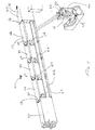
- a monorail switch 10 comprises a moveable guide beam 12 and an actuating mechanism 14.
- the moveable guide beam has a free first end 16 and a second end 18 pivotally connected to a guideway 20.
- the actuating mechanism 14 is connected to the moveable guide beam 12, preferably proximate its first end 16, allowing rotating or bending the moveable guide beam 12 along its whole length.
- the actuating mechanism 14 is operative to laterally displace the moveable guide beam 12 from a tangent position, as shown in Figure 1 , to a turnout position, as shown in Figure 2 .
- the moveable guide beam 12 In the tangent position, the moveable guide beam 12 is aligned with a main portion 22 of the guideway 20 and is oriented according to a first travelling direction 24.
- the turnout position the moveable guide beam 12 is aligned with a diverting portion 26 of the guideway 20 and is oriented with a second travelling direction 28 diverting from the first travelling direction 24.
- the moveable guide beam 12 may be made from an alignment of segments 46 pivotally connected to each other by pivots 50.
- Flexible running surfaces 48 located on each sides of the segments 46, are designed to provide a smooth running surface to a monorail's guide wheels.
- the right and left running surfaces 48 may each be split in two, thereby creating an upper and a lower running surface. This makes for an upper right running surface 48a, a lower right running surface 48b, an upper left running surface 48c and a lower left running surface 48d.
- Creating split running surfaces 48 not only saves weight and material while decreasing lateral stiffness, but also allows the set of upper running surfaces 48a, 48c to behave independently from the set of lower running surfaces 48b and 48d.
- using an alignment of segments 46 makes it easier to manipulate and assemble the segments 46 into the switch when on site, especially considering that this assembly is usually completed at some 15 meters (approximately 49 feet) above the ground.
- the lateral running surfaces 48 extend over at least one of the pivots 50.
- the lateral running surfaces 48 may either be clamped to the guideway 20, as shown in Figure 1 and 2 , may stop at the guideway 20 and be pivotally connected to the guideway 20 or may only be floatingly connected to the moveable guide beam 12.
- the running surfaces 48 provide a smooth transition between the guideway 20 and the moveable guide beam 12, making the monorail entry in the switch 10 much more comfortable for passengers.
- such running surfaces 48 also laterally stiffen the moveable guide beam 12, as the running surfaces 48 act as leaf springs.
- the lateral running surfaces 48 may extend from a position proximate the first end 16 to a position proximate the second end 18 of the moveable guide beam 12.
- the lateral running surfaces 48 may also be split into shorter portions and then assembled together on site. However, it is always preferable that these shorter portions extend at least over one of the pivots 50 connecting two segments 46, and it is also preferable that these shorter portions be rigidly connected to each other so as to provide a continuous smooth curvature of the lateral running surfaces 48.
- the lateral running surfaces 48 located on each side of the moveable guide beam 12 may be interconnected together by a link 52, as best shown in Figures 3 and 4 , now concurrently referred to.
- This link 52 may move laterally with respect to a web 53 of the moveable guide beam 12.
- This interconnection allows providing a more constant distance between two opposed lateral running surfaces 48, thereby preventing loss of guide tire preload and doubling an effective bending stiffness thereby preventing excessive deviation of the guide beam alignment due to dynamic forces as the monorail vehicle traverses the switch.
- the upper right running surface 48a is therefore connected to the upper left running surface 48c and the lower right running surface 48b is connected to the lower left running surface 48d.
- the moveable guide beam 12 may also be equipped with rotation stops 54 between each one of the segments 46.
- the rotation stops 54 prevent two adjacent segments 46 from pivoting beyond a predetermined angle with respect to each other.
- the monorail switch 10 may comprise a similar rotation stop 54 proximate the second end 18 of the moveable guide beam 12 so as to prevent the segment 46 at the second end 18 from pivoting beyond a predetermined angle with respect to the guideway 20.
- Rotation stops 54 may be used on both side of the moveable guide beam 12, thereby prevent two adjacent segments 46 from pivoting beyond a predetermined angle, whether in the turnout position, or in the tangent position.
- the actuating mechanism 14 comprises a lever 30, a counterweight 32 and an actuator 33.
- the lever 30 has a fulcrum 34 and a swinging extremity 36 to which the counterweight 32 is connected.
- the actuator 33 under the control of a controller, is operative to swing the lever 30 around its fulcrum 34, thereby modifying the position of the counterweight 32 and of the moveable guide beam 12.
- the actuator 33 may be any type of known suitable device capable of inducing a motion to the lever 30 and to the counterweight 32 such as, for example, an electromechanical piston, a hydraulic piston, an electric motor, an engine, etc.
- the actuating mechanism 14 is preferably connected proximate the first end 16 of the moveable guide beam 12 and because the lateral running surfaces 48 are connected to each other and extend along the whole length of the moveable guide beam 12, it is possible to use a single actuating mechanism 14, even if the moveable guide beam 12 is made of a linear series of pivotally connected segments 46.
- the lateral running surfaces 48 act as leaf springs smoothly bent when not in their tangent position, precisely guiding the segments 46 in between them.
- the actuating mechanism 14 may be connected to the moveable guide beam 12 either through a linkage 38, through a cable 40 (as best shown in Figure 6 , now concurrently referred to), or through any other known suitable mechanism. If connected with the cable 40, the actuating mechanism 14 uses a cam 42 where the cable 40 interconnects the cam 42 to the moveable guide beam 12. The cable 40 is operative to conform at least partially to a profile 44 of the cam 42 as the moveable guide beam 12 moves from its tangent position to its turnout position.
- the profile of the cam 42 may be designed so that the resulting torque at the fulcrum, developed by the counterweight 32 and a reaction beam flexing force F (the force required to rotate or bend the moveable guide beam 12) of the moveable guide beam 12, is as close to being null as possible.
- F the force required to rotate or bend the moveable guide beam 12
- the actuator 33 needs to develop only a small force to move the moveable guide beam 12. It also means that there is little energy stored in the moveable guide beam 12, thereby reducing risk.
- the counterweight 32 When the actuating mechanism 14 holds the moveable guide beam 12 in the tangent position, as shown in Figure 1 , the counterweight 32 is in a position of high potential energy.
- One such high potential energy position is, for example, when the counterweight 32 is above the fulcrum 34, and more particularly substantially vertically aligned above the fulcrum 34. This is best shown in Figure 3 .
- the counterweight 32 moves downwardly towards a position of low potential energy.
- the potential energy stored in the counterweight 32 is then gradually released and at least partially transferred and stored in the form of elastic potential energy in the lateral running surfaces 48.
- the moveable guide beam 12 reaches the turnout position, as shown in Figure 2 and 4 , the counterweight 32 ends up being vertically offset from the fulcrum 34 in a lower potential energy position, or basically at its lowest potential energy position of its range.
- the elastic potential energy stored in the lateral running surfaces 48 is at least partially gradually transferred and stored in the form of potential energy by the counterweight 32, which then moves from its low potential energy position to its high potential energy position.
- the counterweight 32 is not only offset from the fulcrum 34, but horizontally aligned with the fulcrum 34. This maximizes the moment arm (the perpendicular distance between the fulcrum 34 and a downward vertical force W acting on a center of mass of the counterweight 32). This downward vertical force W corresponds to a weight of the counterweight 32, calculated as the product of its mass M with g, the gravitational constant.
- the linkage 38 is attached approximately 45 degrees offset from the center of mass of the counterweight 32 so that when the counterweight rotates 90 degrees from its starting position directly above the fulcrum 34, the linkage attachment to the actuating mechanism 14 rotates approximately from a -45 degrees to a +45 degrees position with respect to a vertical axis, having as little variation of its effective moment arm as possible.
- the mass M of the counterweight 32 and a length L of the lever 30 are selected so that the sum of torque at the fulcrum 34 is null, or at least relatively low, when the moveable guide beam 12 is in the turnout position, or close to it. This minimizes the force required by the actuator 33 (and consequently reduces its size and its cost) to hold the moveable guide beam 12 in this position.
- the mass M and the length L may be selected so that the sum of torque at the fulcrum 34 is null when the moveable guide beam 12 is at, or proximate, its tangent position. This also minimizes the force required by the actuator 33 to hold the moveable guide beam 12 in this position.
- the counterweight 32 does not have to be exactly vertically above the fulcrum 34 when the moveable guide beam 12 is in the tangent position. Similarly, the counterweight 32 does not have to rotate by exactly 90 degrees around the fulcrum 34 or end up being horizontally aligned with the fulcrum 34 when the moveable guide beam has reached its turnout position. Some variations on the exact position of the counterweight 32 with respect to the fulcrum 34 when the moveable guide beam 12 is in either its tangent or turnout position are possible, as much as variations on the angular displacement of the counterweight 32 around the fulcrum 34, while still providing acceptable results, although maybe not optimal ones.
- Figure 7 depicts a graph of the reaction beam flexing force F and of the weight W as a function of the angular position of the lever 30 (or of the angular position of the counterweight 32 with respect to the fulcrum 34).
- the reaction beam flexing force F or the force required to laterally bend the moveable guide beam 12, results mostly from the effort required to laterally bend lateral running surfaces 48, the rest being some friction between components of the moveable guide beam 12.
- the graph of Figure 7 shows that the reaction beam flexing force F and the weight Ware equal when ⁇ equals 0, 45 and 90 degrees. In between these angular positions, these forces are slightly different, by a factor of approximately 0.08, or 8%.
- the counterweight 32 compensates for at least 92% of the beam flexing force required to move the moveable guide beam 12 from its tangent position to its turnout position. In other words, shall the counterweight 32 be absent, the force required to be developed by the actuator 33 would be much larger.
- a controller 56 receives a command to operate the monorail switch 10 so as to move the moveable guide beam 12 from its tangent position to its turnout position. The controller then sends a signal to the actuator 33 to displace the lever 30 and the counterweight 32 from an initial position where the counterweight 32 is located above the fulcrum 34, as depicted in Figure 3 , to a final position where the counterweight 32 is located beside the fulcrum 34, and approximately horizontally aligned with the fulcrum 34, as depicted in Figure 4 .
- the torque resulting from the product of the weight W and the horizontal distance between the fulcrum 34 and the point of application of the force W (which is applied at the center of mass of the counterweight 32, assuming that the lever 30 and other moveable mass attached to it are relatively negligible with respect to the counterweight 32) gradually increases, at least partially compensating the torque generated by the product of the reaction beam flexing force F with the perpendicular distance between F and the fulcrum 34.
- the controller 56 sends a signal to the actuator 33 to stop. The displacement of the moveable guide beam 12 is then completed.
- the controller 56 may send a signal to the actuator 33 to hold the position and/or a lock may be used to lock the moveable guide beam 12 in place until it has to be moved again.
- the controller 56 sends signals to unlock the moveable guide beam 12 is necessary and to the actuator 33 to move the counterweight 32 back in its original position.
- the controller 56 sends a signal to the actuator 33 to stop. The displacement of the moveable guide beam 12 is then completed.
- the controller 56 may send a signal to the actuator 33 to hold the position and/or a lock may be used to lock the moveable guide beam 12 in place until it has to be moved again.
Landscapes
- Engineering & Computer Science (AREA)
- Mechanical Engineering (AREA)
- Architecture (AREA)
- Civil Engineering (AREA)
- Structural Engineering (AREA)
- Railway Tracks (AREA)
Claims (17)
- Einschienenweiche (10) für eine Einschienen-Führungsbahn (20), wobei die Einschienenweiche (10) umfasst:einen bewegbaren Führungsbalken (12), wobei der bewegbare Führungsbalken (12) ein erstes Ende (16) und ein zweites Ende (18) aufweist, wobei das zweite Ende (18) für eine Verbindung mit der Führungsbahn (20) ausgelegt ist, wobei der bewegbare Führungsbalken (12) laterale Laufflächen (48) auf seiner linken und seiner rechten Seite aufweist;und dadurch gekennzeichnet, dass sie ferner umfasst:einen Betätigungsmechanismus (14), wobei der Betätigungsmechanismus (14) ein Gegengewicht (32) aufweist, wobei der Betätigungsmechanismus (14) so mit dem bewegbaren Führungsbalken (12) verbunden ist, dass er den bewegbaren Führungsbalken (12) von einer tangentialen Position in eine Ausweichposition bewegt,wobei potentielle Energie, die in dem Gegengewicht (32) gespeichert ist, freigegeben und zumindest zum Teil in Form von elastischer potentieller Energie in den lateralen Laufflächen (48) gespeichert wird, wenn der bewegbare Führungsbalken (12) aus der tangentialen Position in die Ausweichposition bewegt wird; undwobei die elastische potentielle Energie, die in den lateralen Laufflächen (48) gespeichert ist, freigegeben und zumindest zum Teil in Form von elastischer potentieller Energie in dem Gegengewicht (32) gespeichert wird, wenn der bewegbare Führungsbalken (12) aus der Ausweichposition in die tangentiale Position bewegt wird.
- Einschienenweiche (10) nach Anspruch 1, wobei das Gegengewicht (32) eine Position mit hoher potentieller Energie einnimmt, wenn der bewegbare Führungsbalken (12) die tangentiale Position einnimmt, und wobei das Gegengewicht (32) eine Position mit niedriger potentieller Energie einnimmt, wenn der bewegbare Führungsbalken (12) die Ausweichposition einnimmt.
- Einschienenweiche (10) nach Anspruch 2, wobei der Betätigungsmechanismus (14) ferner einen Hebel (30) umfasst, wobei der Hebel (30) einen Drehpunkt (34) und einen schwingenden äußeren Teil (36) aufweist, wobei das Gegengewicht (32) mit dem schwingenden äußeren Teil (36) verbunden ist.
- Einschienenweiche (10) nach Anspruch 3, wobei das Gegengewicht (32) im Wesentlichen vertikal über dem Drehpunkt (34) ausgerichtet ist, wenn der bewegbare Führungsbalken (12) die tangentiale Position einnimmt, und wobei das Gegengewicht (32) vertikal von dem Drehpunkt (34) verlagert ist, wenn der bewegbare Führungsbalken (12) die Ausweichposition einnimmt.
- Einschienenweiche (10) nach Anspruch 4, wobei das Gegengewicht (32) horizontal an dem Drehpunkt (34) ausgerichtet ist, wenn der bewegbare Führungsbalken (12) die Ausweichposition einnimmt.
- Einschienenweiche (10) nach Anspruch 3, wobei das Gegengewicht (32) eine Masse M aufweist, und wobei der Hebel eine Länge L aufweist, wobei die Masse M und die Länge L so ausgewählt werden, dass eine Summe eines Drehmoments an dem Drehpunkt (34) null ist, wenn sich der bewegbare Führungsbalken (12) nahe der Ausweichposition befindet.
- Einschienenweiche (10) nach Anspruch 6, wobei die Masse M und die Länge L so ausgewählt werden, dass die Summe eines Drehmoments an dem Drehpunkt null ist, wenn sich der bewegbare Führungsbalken (12) in der Nähe der tangentialen Position befindet.
- Einschienenweiche (10) nach Anspruch 1, wobei der Betätigungsmechanismus mit dem bewegbaren Führungsbalken (12) nahe dem ersten Ende (16) verbunden ist.
- Einschienenweiche (10) nach Anspruch 1, wobei sich die lateralen Laufflächen (48) von einer Position in der Nähe des ersten Endes (16) zu einer Position in der Nähe des zweiten Endes (18) erstrecken.
- Einschienenweiche (10) nach Anspruch 1, wobei die lateralen Laufflächen (48) einen oberen Satz und einen unteren Satz von Laufflächen (48) umfassen, wobei die Laufflächen (48) des oberen Satzes miteinander verbunden sind und die Laufflächen (48) des unteren Satzes miteinander verbunden sind.
- Einschienenweiche (10) nach Anspruch 1, wobei der bewegbare Führungsbalken (12) eine Reihe von Segmenten (46) umfasst, die drehbar Ende-an-Ende durch Drehstifte (50) miteinander verbunden sind, wobei sich die lateralen Laufflächen (48) auf jeder Seite der Segmente (46) erstrecken.
- Einschienenweiche (10) nach Anspruch 11, wobei der bewegbare Führungsbalken (12) ferner Drehanschläge (54) zwischen den einzelnen Segmenten (46) umfasst, wobei die Drehanschläge (54) verhindern, dass zwei benachbarte Segmente (46) über einen vorgegebenen Winkel in Bezug aufeinander hinaus ausschwenken.
- Einschienenweiche (10) nach Anspruch 12, ferner einen anderen Drehanschlag (54) nahe dem zweiten Ende (18) umfassend, um zu verhindern, dass das Segment (46) an dem zweiten Ende (18) über einen vorgegebenen Winkel in Bezug auf die Führungsbahn (20) hinaus ausschwenkt.
- Einschienenweiche (10) nach Anspruch 11, höchstens einen von den Betätigungsmechanismen (14) umfassend, wobei der Betätigungsmechanismus (14) mit einem einzigen von den Segmenten (46) verbunden ist, welches das erste Ende (16) des bewegbaren Führungsbalkens (12) aufweist.
- Einschienenweiche (10) nach Anspruch 1, wobei der Betätigungsmechanismus (14) über eine Verbindung (38) mit dem bewegbaren Führungsbalken (12) verbunden ist.
- Einschienenweiche (10) nach Anspruch 1, wobei der Betätigungsmechanismus (14) ferner einen Nocken (42) und ein Kabel (40) umfasst, wobei das Kabel (40) den Nocken (42) mit dem bewegbaren Führungsbalken (12) verbindet, wobei das Kabel (40) die Funktion hat, zumindest zum Teil einem Profil des Nockens (42) zu entsprechen, wenn sich der bewegbare Führungsbalken (12) von der tangentialen Position zu der Ausweichposition bewegt.
- Einschienenweiche (10) nach Anspruch 1, ferner einen Sperrmechanismus umfassend, wobei der Sperrmechanismus die Funktion hat, den bewegbaren Führungsbalken (12) selektiv in entweder der tangentialen Position oder der Ausweichposition zu verriegeln.
Applications Claiming Priority (2)
| Application Number | Priority Date | Filing Date | Title |
|---|---|---|---|
| US201562218676P | 2015-09-15 | 2015-09-15 | |
| PCT/IB2016/055509 WO2017046741A1 (en) | 2015-09-15 | 2016-09-15 | Monorail switch using a gravity-assisted actuating mechanism |
Publications (2)
| Publication Number | Publication Date |
|---|---|
| EP3380385A1 EP3380385A1 (de) | 2018-10-03 |
| EP3380385B1 true EP3380385B1 (de) | 2020-11-11 |
Family
ID=56990681
Family Applications (1)
| Application Number | Title | Priority Date | Filing Date |
|---|---|---|---|
| EP16770563.1A Not-in-force EP3380385B1 (de) | 2015-09-15 | 2016-09-15 | Einschienenbahnschalter mit schwerkraftgestütztem betätigungsmechanismus |
Country Status (4)
| Country | Link |
|---|---|
| US (1) | US10858788B2 (de) |
| EP (1) | EP3380385B1 (de) |
| CN (1) | CN106795698B (de) |
| WO (1) | WO2017046741A1 (de) |
Families Citing this family (11)
| Publication number | Priority date | Publication date | Assignee | Title |
|---|---|---|---|---|
| CN109204382B (zh) * | 2017-06-30 | 2020-11-06 | 比亚迪股份有限公司 | 道岔转辙驱动装置和道岔 |
| CN109204381B (zh) * | 2017-06-30 | 2020-06-19 | 比亚迪股份有限公司 | 用于道岔的柔性驱动装置 |
| CN109204380B (zh) * | 2017-06-30 | 2020-06-19 | 比亚迪股份有限公司 | 道岔挠曲装置及可挠型道岔 |
| CN109552359A (zh) * | 2018-12-12 | 2019-04-02 | 锡矿山闪星锑业有限责任公司 | 一种手动杠杆式扳道机 |
| CN110565454A (zh) * | 2019-10-12 | 2019-12-13 | 株洲中车特种装备科技有限公司 | 一种用于道岔的滑触线过渡接头 |
| CN112744256B (zh) * | 2019-10-31 | 2023-11-03 | 江苏飞梭智行设备有限公司 | 一种升降式变轨装置 |
| DE102019135569A1 (de) * | 2019-12-20 | 2021-06-24 | Max Bögl Stiftung & Co. Kg | Weichenanordnung für ein spurgebundenes Fahrzeug |
| CN113403893A (zh) * | 2020-03-16 | 2021-09-17 | 中国航天科工飞航技术研究院(中国航天海鹰机电技术研究院) | 挠性u型轨道梁及具有其的真空管道道岔结构 |
| DE102020120653B4 (de) * | 2020-08-05 | 2023-02-23 | Technische Hochschule Ostwestfalen-Lippe, Körperschaft des öffentlichen Rechts | Umsetzen eines Einschienenfahrzeugs |
| CN113353794B (zh) * | 2021-06-04 | 2022-06-24 | 中交二航局第二工程有限公司 | 一种可水平弯折的无缝连接轨道 |
| CN117090085B (zh) * | 2023-08-31 | 2025-11-04 | 羿鹏轨道交通开发(上海)有限公司 | 一种悬挂式单轨交通用道岔的使用方法 |
Family Cites Families (14)
| Publication number | Priority date | Publication date | Assignee | Title |
|---|---|---|---|---|
| GB110420A (en) * | 1916-11-02 | 1917-10-25 | Alfred Morgan | Improvements in Points and Switches for Railways and Tramways. |
| US3472176A (en) * | 1966-12-23 | 1969-10-14 | North American Rockwell | Deflecting beam monorail switch |
| JPH0464509A (ja) * | 1990-04-24 | 1992-02-28 | Nichidai Kogyo Kk | フレキシブルレールとフレキシブル搬送装置、並びに、その部品塗装装置 |
| DE4416820C2 (de) * | 1994-05-16 | 1999-07-01 | Butzbacher Weichenbau Gmbh | Biegeweiche |
| CN2389809Y (zh) * | 1999-11-01 | 2000-08-02 | 铁道部专业设计院 | 多关节道岔转辙驱动装置 |
| US20040225421A1 (en) * | 2003-05-05 | 2004-11-11 | Hengning Wu | Personal transportation system |
| AT502080B1 (de) * | 2005-06-13 | 2007-08-15 | Alexander Dr Lechner | Transportanlage |
| DE102007038498B4 (de) * | 2007-08-14 | 2016-10-20 | Sew-Eurodrive Gmbh & Co Kg | Anlage |
| WO2009059362A1 (en) * | 2007-11-06 | 2009-05-14 | Ubeauti Pty Ltd | A monorail rapid transit system |
| CN201250372Y (zh) * | 2008-06-05 | 2009-06-03 | 重庆齿轮箱有限责任公司 | 跨座式单轨简易可挠式道岔 |
| CN201354081Y (zh) * | 2009-03-02 | 2009-12-02 | 灵宝市金源矿业有限责任公司 | 一种用于道岔变道的操作机构 |
| FI20125085L (fi) * | 2012-01-27 | 2013-07-28 | Vr Track Oy | Järjestely kiskoliikennevaihteeseen |
| US9644325B2 (en) | 2014-04-29 | 2017-05-09 | Bombardier Transportation Gmbh | Cross-over switch for a monorail |
| CN204506927U (zh) * | 2015-02-13 | 2015-07-29 | 山西省长治经坊煤业有限公司 | 地下手动扳道器 |
-
2016
- 2016-09-15 EP EP16770563.1A patent/EP3380385B1/de not_active Not-in-force
- 2016-09-15 CN CN201680002289.8A patent/CN106795698B/zh not_active Expired - Fee Related
- 2016-09-15 US US15/751,891 patent/US10858788B2/en not_active Expired - Fee Related
- 2016-09-15 WO PCT/IB2016/055509 patent/WO2017046741A1/en not_active Ceased
Non-Patent Citations (1)
| Title |
|---|
| None * |
Also Published As
| Publication number | Publication date |
|---|---|
| CN106795698B (zh) | 2018-11-30 |
| US20180230657A1 (en) | 2018-08-16 |
| WO2017046741A1 (en) | 2017-03-23 |
| CN106795698A (zh) | 2017-05-31 |
| US10858788B2 (en) | 2020-12-08 |
| EP3380385A1 (de) | 2018-10-03 |
Similar Documents
| Publication | Publication Date | Title |
|---|---|---|
| EP3380385B1 (de) | Einschienenbahnschalter mit schwerkraftgestütztem betätigungsmechanismus | |
| JP7426014B2 (ja) | レールスイッチングユニット | |
| US9212454B2 (en) | Branching device and center guide-type track-based transportation system | |
| KR20020024767A (ko) | 철도차량 | |
| JPS6132441B2 (de) | ||
| CN107249926B (zh) | 用于运输系统的悬浮控制系统 | |
| AU2018236831B2 (en) | Car with rotatably mounted wheel axle for a fairground ride and method for controlling a rotatably mounted wheel axle of such a car | |
| US5287811A (en) | Flexible branching apparatus in superconducting magnetically levitated railway having variable cross-section main flexible beam | |
| KR20010077501A (ko) | 선형유도모터를 차량바닥에 장착한 피알티시스템 | |
| AU674429B2 (en) | Switches for automated guideway transit systems | |
| US4271765A (en) | Railway car tilting stabilizing system | |
| CA2390909C (en) | Device for radially controlling a rail vehicle | |
| US12540441B2 (en) | Switch arrangement for a track-borne vehicle | |
| EP3898316A1 (de) | Stabilisierungs-und levitationsmechanismus für ein dediziertes fahrzeug unter berücksichtigung der interoperabilität mit bestehenden transportsystemen in der nähe von schaltern und routen herkömmlicher fahrzeuge und wie das fahrzeug in der stabilisierungs-und schwebevorrichtung stabilisiert ist | |
| JP2517792B2 (ja) | 鉄道の分岐装置における案内レ―ルの操作装置 | |
| CN112706630B (zh) | 一种升降装置及充电结构 | |
| RU2248285C2 (ru) | Подвесная канатная дорога | |
| JP2530062B2 (ja) | 鉄道の分岐装置 | |
| JPH04161501A (ja) | 鉄道の分岐装置における案内レールの操作装置 | |
| HK1033842B (zh) | 磁悬浮列车车轨的变线设备 | |
| US748508A (en) | Switch-operating apparatus for tramway or other cars. | |
| HK1033842A1 (en) | Line-changing device for tracks of a magnetic levitation train | |
| WO2018096570A1 (ja) | 跨座型モノレール分岐器 | |
| SE510725C3 (sv) | Vagn foer spaarbundet fordon med lutningsanordning | |
| JPWO1992003616A1 (ja) | 桁式転てつ軌道 |
Legal Events
| Date | Code | Title | Description |
|---|---|---|---|
| STAA | Information on the status of an ep patent application or granted ep patent |
Free format text: STATUS: THE INTERNATIONAL PUBLICATION HAS BEEN MADE |
|
| PUAI | Public reference made under article 153(3) epc to a published international application that has entered the european phase |
Free format text: ORIGINAL CODE: 0009012 |
|
| STAA | Information on the status of an ep patent application or granted ep patent |
Free format text: STATUS: REQUEST FOR EXAMINATION WAS MADE |
|
| 17P | Request for examination filed |
Effective date: 20180719 |
|
| AK | Designated contracting states |
Kind code of ref document: A1 Designated state(s): AL AT BE BG CH CY CZ DE DK EE ES FI FR GB GR HR HU IE IS IT LI LT LU LV MC MK MT NL NO PL PT RO RS SE SI SK SM TR |
|
| AX | Request for extension of the european patent |
Extension state: BA ME |
|
| DAV | Request for validation of the european patent (deleted) | ||
| DAX | Request for extension of the european patent (deleted) | ||
| GRAP | Despatch of communication of intention to grant a patent |
Free format text: ORIGINAL CODE: EPIDOSNIGR1 |
|
| STAA | Information on the status of an ep patent application or granted ep patent |
Free format text: STATUS: GRANT OF PATENT IS INTENDED |
|
| INTG | Intention to grant announced |
Effective date: 20200603 |
|
| GRAS | Grant fee paid |
Free format text: ORIGINAL CODE: EPIDOSNIGR3 |
|
| GRAA | (expected) grant |
Free format text: ORIGINAL CODE: 0009210 |
|
| STAA | Information on the status of an ep patent application or granted ep patent |
Free format text: STATUS: THE PATENT HAS BEEN GRANTED |
|
| AK | Designated contracting states |
Kind code of ref document: B1 Designated state(s): AL AT BE BG CH CY CZ DE DK EE ES FI FR GB GR HR HU IE IS IT LI LT LU LV MC MK MT NL NO PL PT RO RS SE SI SK SM TR |
|
| REG | Reference to a national code |
Ref country code: GB Ref legal event code: FG4D |
|
| REG | Reference to a national code |
Ref country code: CH Ref legal event code: EP |
|
| REG | Reference to a national code |
Ref country code: AT Ref legal event code: REF Ref document number: 1333192 Country of ref document: AT Kind code of ref document: T Effective date: 20201115 |
|
| REG | Reference to a national code |
Ref country code: DE Ref legal event code: R096 Ref document number: 602016047710 Country of ref document: DE |
|
| REG | Reference to a national code |
Ref country code: IE Ref legal event code: FG4D |
|
| REG | Reference to a national code |
Ref country code: DE Ref legal event code: R082 Ref document number: 602016047710 Country of ref document: DE |
|
| REG | Reference to a national code |
Ref country code: NL Ref legal event code: MP Effective date: 20201111 |
|
| REG | Reference to a national code |
Ref country code: AT Ref legal event code: MK05 Ref document number: 1333192 Country of ref document: AT Kind code of ref document: T Effective date: 20201111 |
|
| PG25 | Lapsed in a contracting state [announced via postgrant information from national office to epo] |
Ref country code: RS Free format text: LAPSE BECAUSE OF FAILURE TO SUBMIT A TRANSLATION OF THE DESCRIPTION OR TO PAY THE FEE WITHIN THE PRESCRIBED TIME-LIMIT Effective date: 20201111 Ref country code: PT Free format text: LAPSE BECAUSE OF FAILURE TO SUBMIT A TRANSLATION OF THE DESCRIPTION OR TO PAY THE FEE WITHIN THE PRESCRIBED TIME-LIMIT Effective date: 20210311 Ref country code: NO Free format text: LAPSE BECAUSE OF FAILURE TO SUBMIT A TRANSLATION OF THE DESCRIPTION OR TO PAY THE FEE WITHIN THE PRESCRIBED TIME-LIMIT Effective date: 20210211 Ref country code: FI Free format text: LAPSE BECAUSE OF FAILURE TO SUBMIT A TRANSLATION OF THE DESCRIPTION OR TO PAY THE FEE WITHIN THE PRESCRIBED TIME-LIMIT Effective date: 20201111 Ref country code: GR Free format text: LAPSE BECAUSE OF FAILURE TO SUBMIT A TRANSLATION OF THE DESCRIPTION OR TO PAY THE FEE WITHIN THE PRESCRIBED TIME-LIMIT Effective date: 20210212 |
|
| PG25 | Lapsed in a contracting state [announced via postgrant information from national office to epo] |
Ref country code: AT Free format text: LAPSE BECAUSE OF FAILURE TO SUBMIT A TRANSLATION OF THE DESCRIPTION OR TO PAY THE FEE WITHIN THE PRESCRIBED TIME-LIMIT Effective date: 20201111 Ref country code: IS Free format text: LAPSE BECAUSE OF FAILURE TO SUBMIT A TRANSLATION OF THE DESCRIPTION OR TO PAY THE FEE WITHIN THE PRESCRIBED TIME-LIMIT Effective date: 20210311 Ref country code: PL Free format text: LAPSE BECAUSE OF FAILURE TO SUBMIT A TRANSLATION OF THE DESCRIPTION OR TO PAY THE FEE WITHIN THE PRESCRIBED TIME-LIMIT Effective date: 20201111 Ref country code: LV Free format text: LAPSE BECAUSE OF FAILURE TO SUBMIT A TRANSLATION OF THE DESCRIPTION OR TO PAY THE FEE WITHIN THE PRESCRIBED TIME-LIMIT Effective date: 20201111 Ref country code: BG Free format text: LAPSE BECAUSE OF FAILURE TO SUBMIT A TRANSLATION OF THE DESCRIPTION OR TO PAY THE FEE WITHIN THE PRESCRIBED TIME-LIMIT Effective date: 20210211 Ref country code: SE Free format text: LAPSE BECAUSE OF FAILURE TO SUBMIT A TRANSLATION OF THE DESCRIPTION OR TO PAY THE FEE WITHIN THE PRESCRIBED TIME-LIMIT Effective date: 20201111 |
|
| REG | Reference to a national code |
Ref country code: LT Ref legal event code: MG9D |
|
| PG25 | Lapsed in a contracting state [announced via postgrant information from national office to epo] |
Ref country code: HR Free format text: LAPSE BECAUSE OF FAILURE TO SUBMIT A TRANSLATION OF THE DESCRIPTION OR TO PAY THE FEE WITHIN THE PRESCRIBED TIME-LIMIT Effective date: 20201111 |
|
| PG25 | Lapsed in a contracting state [announced via postgrant information from national office to epo] |
Ref country code: LT Free format text: LAPSE BECAUSE OF FAILURE TO SUBMIT A TRANSLATION OF THE DESCRIPTION OR TO PAY THE FEE WITHIN THE PRESCRIBED TIME-LIMIT Effective date: 20201111 Ref country code: SM Free format text: LAPSE BECAUSE OF FAILURE TO SUBMIT A TRANSLATION OF THE DESCRIPTION OR TO PAY THE FEE WITHIN THE PRESCRIBED TIME-LIMIT Effective date: 20201111 Ref country code: CZ Free format text: LAPSE BECAUSE OF FAILURE TO SUBMIT A TRANSLATION OF THE DESCRIPTION OR TO PAY THE FEE WITHIN THE PRESCRIBED TIME-LIMIT Effective date: 20201111 Ref country code: EE Free format text: LAPSE BECAUSE OF FAILURE TO SUBMIT A TRANSLATION OF THE DESCRIPTION OR TO PAY THE FEE WITHIN THE PRESCRIBED TIME-LIMIT Effective date: 20201111 Ref country code: RO Free format text: LAPSE BECAUSE OF FAILURE TO SUBMIT A TRANSLATION OF THE DESCRIPTION OR TO PAY THE FEE WITHIN THE PRESCRIBED TIME-LIMIT Effective date: 20201111 Ref country code: SK Free format text: LAPSE BECAUSE OF FAILURE TO SUBMIT A TRANSLATION OF THE DESCRIPTION OR TO PAY THE FEE WITHIN THE PRESCRIBED TIME-LIMIT Effective date: 20201111 |
|
| REG | Reference to a national code |
Ref country code: DE Ref legal event code: R097 Ref document number: 602016047710 Country of ref document: DE |
|
| PG25 | Lapsed in a contracting state [announced via postgrant information from national office to epo] |
Ref country code: DK Free format text: LAPSE BECAUSE OF FAILURE TO SUBMIT A TRANSLATION OF THE DESCRIPTION OR TO PAY THE FEE WITHIN THE PRESCRIBED TIME-LIMIT Effective date: 20201111 |
|
| PLBE | No opposition filed within time limit |
Free format text: ORIGINAL CODE: 0009261 |
|
| STAA | Information on the status of an ep patent application or granted ep patent |
Free format text: STATUS: NO OPPOSITION FILED WITHIN TIME LIMIT |
|
| 26N | No opposition filed |
Effective date: 20210812 |
|
| PG25 | Lapsed in a contracting state [announced via postgrant information from national office to epo] |
Ref country code: NL Free format text: LAPSE BECAUSE OF FAILURE TO SUBMIT A TRANSLATION OF THE DESCRIPTION OR TO PAY THE FEE WITHIN THE PRESCRIBED TIME-LIMIT Effective date: 20201111 Ref country code: AL Free format text: LAPSE BECAUSE OF FAILURE TO SUBMIT A TRANSLATION OF THE DESCRIPTION OR TO PAY THE FEE WITHIN THE PRESCRIBED TIME-LIMIT Effective date: 20201111 Ref country code: IT Free format text: LAPSE BECAUSE OF FAILURE TO SUBMIT A TRANSLATION OF THE DESCRIPTION OR TO PAY THE FEE WITHIN THE PRESCRIBED TIME-LIMIT Effective date: 20201111 |
|
| PGFP | Annual fee paid to national office [announced via postgrant information from national office to epo] |
Ref country code: FR Payment date: 20210922 Year of fee payment: 6 |
|
| PG25 | Lapsed in a contracting state [announced via postgrant information from national office to epo] |
Ref country code: SI Free format text: LAPSE BECAUSE OF FAILURE TO SUBMIT A TRANSLATION OF THE DESCRIPTION OR TO PAY THE FEE WITHIN THE PRESCRIBED TIME-LIMIT Effective date: 20201111 |
|
| PGFP | Annual fee paid to national office [announced via postgrant information from national office to epo] |
Ref country code: DE Payment date: 20210920 Year of fee payment: 6 Ref country code: GB Payment date: 20210920 Year of fee payment: 6 |
|
| PG25 | Lapsed in a contracting state [announced via postgrant information from national office to epo] |
Ref country code: ES Free format text: LAPSE BECAUSE OF FAILURE TO SUBMIT A TRANSLATION OF THE DESCRIPTION OR TO PAY THE FEE WITHIN THE PRESCRIBED TIME-LIMIT Effective date: 20201111 |
|
| REG | Reference to a national code |
Ref country code: CH Ref legal event code: PL |
|
| REG | Reference to a national code |
Ref country code: BE Ref legal event code: MM Effective date: 20210930 |
|
| PG25 | Lapsed in a contracting state [announced via postgrant information from national office to epo] |
Ref country code: IS Free format text: LAPSE BECAUSE OF FAILURE TO SUBMIT A TRANSLATION OF THE DESCRIPTION OR TO PAY THE FEE WITHIN THE PRESCRIBED TIME-LIMIT Effective date: 20210311 Ref country code: MC Free format text: LAPSE BECAUSE OF FAILURE TO SUBMIT A TRANSLATION OF THE DESCRIPTION OR TO PAY THE FEE WITHIN THE PRESCRIBED TIME-LIMIT Effective date: 20201111 |
|
| PG25 | Lapsed in a contracting state [announced via postgrant information from national office to epo] |
Ref country code: LU Free format text: LAPSE BECAUSE OF NON-PAYMENT OF DUE FEES Effective date: 20210915 Ref country code: IE Free format text: LAPSE BECAUSE OF NON-PAYMENT OF DUE FEES Effective date: 20210915 Ref country code: BE Free format text: LAPSE BECAUSE OF NON-PAYMENT OF DUE FEES Effective date: 20210930 |
|
| PG25 | Lapsed in a contracting state [announced via postgrant information from national office to epo] |
Ref country code: LI Free format text: LAPSE BECAUSE OF NON-PAYMENT OF DUE FEES Effective date: 20210930 Ref country code: CH Free format text: LAPSE BECAUSE OF NON-PAYMENT OF DUE FEES Effective date: 20210930 |
|
| REG | Reference to a national code |
Ref country code: DE Ref legal event code: R119 Ref document number: 602016047710 Country of ref document: DE |
|
| GBPC | Gb: european patent ceased through non-payment of renewal fee |
Effective date: 20220915 |
|
| PG25 | Lapsed in a contracting state [announced via postgrant information from national office to epo] |
Ref country code: CY Free format text: LAPSE BECAUSE OF FAILURE TO SUBMIT A TRANSLATION OF THE DESCRIPTION OR TO PAY THE FEE WITHIN THE PRESCRIBED TIME-LIMIT Effective date: 20201111 |
|
| PG25 | Lapsed in a contracting state [announced via postgrant information from national office to epo] |
Ref country code: HU Free format text: LAPSE BECAUSE OF FAILURE TO SUBMIT A TRANSLATION OF THE DESCRIPTION OR TO PAY THE FEE WITHIN THE PRESCRIBED TIME-LIMIT; INVALID AB INITIO Effective date: 20160915 Ref country code: FR Free format text: LAPSE BECAUSE OF NON-PAYMENT OF DUE FEES Effective date: 20220930 Ref country code: DE Free format text: LAPSE BECAUSE OF NON-PAYMENT OF DUE FEES Effective date: 20230401 |
|
| PG25 | Lapsed in a contracting state [announced via postgrant information from national office to epo] |
Ref country code: GB Free format text: LAPSE BECAUSE OF NON-PAYMENT OF DUE FEES Effective date: 20220915 |
|
| PG25 | Lapsed in a contracting state [announced via postgrant information from national office to epo] |
Ref country code: MK Free format text: LAPSE BECAUSE OF FAILURE TO SUBMIT A TRANSLATION OF THE DESCRIPTION OR TO PAY THE FEE WITHIN THE PRESCRIBED TIME-LIMIT Effective date: 20201111 |
|
| PG25 | Lapsed in a contracting state [announced via postgrant information from national office to epo] |
Ref country code: TR Free format text: LAPSE BECAUSE OF FAILURE TO SUBMIT A TRANSLATION OF THE DESCRIPTION OR TO PAY THE FEE WITHIN THE PRESCRIBED TIME-LIMIT Effective date: 20201111 |
|
| PG25 | Lapsed in a contracting state [announced via postgrant information from national office to epo] |
Ref country code: MT Free format text: LAPSE BECAUSE OF FAILURE TO SUBMIT A TRANSLATION OF THE DESCRIPTION OR TO PAY THE FEE WITHIN THE PRESCRIBED TIME-LIMIT Effective date: 20201111 |