EP3381027B1 - Simulateur de grues, de machines de chantier ou de chariots de manutention - Google Patents
Simulateur de grues, de machines de chantier ou de chariots de manutention Download PDFInfo
- Publication number
- EP3381027B1 EP3381027B1 EP17700592.3A EP17700592A EP3381027B1 EP 3381027 B1 EP3381027 B1 EP 3381027B1 EP 17700592 A EP17700592 A EP 17700592A EP 3381027 B1 EP3381027 B1 EP 3381027B1
- Authority
- EP
- European Patent Office
- Prior art keywords
- crane
- movement
- control
- machine
- simulator
- Prior art date
- Legal status (The legal status is an assumption and is not a legal conclusion. Google has not performed a legal analysis and makes no representation as to the accuracy of the status listed.)
- Active
Links
Images


Classifications
-
- G—PHYSICS
- G09—EDUCATION; CRYPTOGRAPHY; DISPLAY; ADVERTISING; SEALS
- G09B—EDUCATIONAL OR DEMONSTRATION APPLIANCES; APPLIANCES FOR TEACHING, OR COMMUNICATING WITH, THE BLIND, DEAF OR MUTE; MODELS; PLANETARIA; GLOBES; MAPS; DIAGRAMS
- G09B9/00—Simulators for teaching or training purposes
- G09B9/02—Simulators for teaching or training purposes for teaching control of vehicles or other craft
- G09B9/04—Simulators for teaching or training purposes for teaching control of vehicles or other craft for teaching control of land vehicles
- G09B9/05—Simulators for teaching or training purposes for teaching control of vehicles or other craft for teaching control of land vehicles the view from a vehicle being simulated
-
- B—PERFORMING OPERATIONS; TRANSPORTING
- B66—HOISTING; LIFTING; HAULING
- B66C—CRANES; LOAD-ENGAGING ELEMENTS OR DEVICES FOR CRANES, CAPSTANS, WINCHES, OR TACKLES
- B66C13/00—Other constructional features or details
- B66C13/18—Control systems or devices
- B66C13/40—Applications of devices for transmitting control pulses; Applications of remote control devices
-
- B—PERFORMING OPERATIONS; TRANSPORTING
- B66—HOISTING; LIFTING; HAULING
- B66C—CRANES; LOAD-ENGAGING ELEMENTS OR DEVICES FOR CRANES, CAPSTANS, WINCHES, OR TACKLES
- B66C13/00—Other constructional features or details
- B66C13/18—Control systems or devices
- B66C13/46—Position indicators for suspended loads or for crane elements
-
- B—PERFORMING OPERATIONS; TRANSPORTING
- B66—HOISTING; LIFTING; HAULING
- B66C—CRANES; LOAD-ENGAGING ELEMENTS OR DEVICES FOR CRANES, CAPSTANS, WINCHES, OR TACKLES
- B66C13/00—Other constructional features or details
- B66C13/52—Details of compartments for driving engines or motors or of operator's stands or cabins
- B66C13/54—Operator's stands or cabins
-
- E—FIXED CONSTRUCTIONS
- E02—HYDRAULIC ENGINEERING; FOUNDATIONS; SOIL SHIFTING
- E02F—DREDGING; SOIL-SHIFTING
- E02F9/00—Component parts of dredgers or soil-shifting machines, not restricted to one of the kinds covered by groups E02F3/00 - E02F7/00
- E02F9/16—Cabins, platforms, or the like, for drivers
- E02F9/166—Cabins, platforms, or the like, for drivers movable, tiltable or pivoting, e.g. movable seats, dampening arrangements of cabins
-
- E—FIXED CONSTRUCTIONS
- E02—HYDRAULIC ENGINEERING; FOUNDATIONS; SOIL SHIFTING
- E02F—DREDGING; SOIL-SHIFTING
- E02F9/00—Component parts of dredgers or soil-shifting machines, not restricted to one of the kinds covered by groups E02F3/00 - E02F7/00
- E02F9/20—Drives; Control devices
- E02F9/2004—Control mechanisms, e.g. control levers
-
- E—FIXED CONSTRUCTIONS
- E02—HYDRAULIC ENGINEERING; FOUNDATIONS; SOIL SHIFTING
- E02F—DREDGING; SOIL-SHIFTING
- E02F9/00—Component parts of dredgers or soil-shifting machines, not restricted to one of the kinds covered by groups E02F3/00 - E02F7/00
- E02F9/20—Drives; Control devices
- E02F9/2025—Particular purposes of control systems not otherwise provided for
- E02F9/205—Remotely operated machines, e.g. unmanned vehicles
-
- E—FIXED CONSTRUCTIONS
- E02—HYDRAULIC ENGINEERING; FOUNDATIONS; SOIL SHIFTING
- E02F—DREDGING; SOIL-SHIFTING
- E02F9/00—Component parts of dredgers or soil-shifting machines, not restricted to one of the kinds covered by groups E02F3/00 - E02F7/00
- E02F9/26—Indicating devices
- E02F9/264—Sensors and their calibration for indicating the position of the work tool
-
- G—PHYSICS
- G09—EDUCATION; CRYPTOGRAPHY; DISPLAY; ADVERTISING; SEALS
- G09B—EDUCATIONAL OR DEMONSTRATION APPLIANCES; APPLIANCES FOR TEACHING, OR COMMUNICATING WITH, THE BLIND, DEAF OR MUTE; MODELS; PLANETARIA; GLOBES; MAPS; DIAGRAMS
- G09B9/00—Simulators for teaching or training purposes
- G09B9/02—Simulators for teaching or training purposes for teaching control of vehicles or other craft
- G09B9/08—Simulators for teaching or training purposes for teaching control of vehicles or other craft for teaching control of aircraft, e.g. Link trainer
- G09B9/16—Ambient or aircraft conditions simulated or indicated by instrument or alarm
- G09B9/165—Condition of cabin, cockpit or pilot's accessories
Definitions
- the present invention relates to a simulator for a crane, a construction machine or an industrial truck, with a control stand which has at least one input means for entering control commands, a graphic simulation module for calculating a virtual representation of the machine environment and / or machine components visible from the control stand such as Boom or load hook, as well as a display device for displaying the calculated virtual representation, with a motion simulation module for determining movements and / or deformations of the machine components depending on the input control commands, depending on which the graphic simulation module calculates the virtual representation.
- Cranes and similar large devices such as hammer drills, surface miners or rope shovels are very complex to operate and control and therefore difficult to learn, so that common training and teaching materials such as photos, plans or even films are not sufficient to actually make operation and monitoring clear convey and make it easy to learn.
- This is not just about the multitude of control functions and their interaction as well as the associated ones
- the associated, in their entirety quite complex input means such as joysticks, foot pedals and control switches are a problem, but also the often unfamiliar, machine-specific reactions of the machine structure to movements of the actuators.
- the tower structure and the boom system can, for example, deform the tower structure and the boom system when a load is picked up, or the load can oscillate when rotating around the upright axis and the boom can oscillate accordingly.
- Something similar can occur with rope excavators or hammer drills, so that a crane operator or machine operator becomes unsure if he applies the control processes that have been safely learned in theory in practice and experiences the corresponding crane reactions.
- the graphic simulation module calculates the representation of the crane environment in such a way that it moves on the screen from right to left or vice versa, so that the virtual crane environment shown on the display device is on The crane operator wanders past in a similar way to what happens when a crane is "real" twisted in its crane cabin.
- a control command is entered which, for example, lowers the load hook and / or rocks the boom
- the graphic simulation module changes the virtual representation in such a way that the crane hook moves downwards on the display device or the boom rocks.
- Such a realistic simulation of the crane operation gives the crane operator a sense of what the reactions are to an actuation of the input means of the control station.
- Such a crane simulator is from the document, for example DE 10 2013 011 818 A1 famous.
- a crane operator's cab is provided there as a control stand with appropriate input means, the viewing windows or the glazing of the simulated crane operator's cab being replaced by screens on which the virtual representation of the crane environment is displayed.
- a technical simulation module is used to simulate the dynamic behavior of the control and drive components and to take them into account in the screen display, with the setting movements of crane components such as the hoist that occur during certain crane movements being shown here.
- the present invention is based on the object of creating an improved simulator of the type mentioned at the beginning, which avoids the disadvantages of the prior art and further develops the latter in an advantageous manner.
- a more realistic simulation of the crane or machine operation is to be achieved, which improves the training effect and communicates the actual crane or machine behavior better and makes it easier to learn.
- Such a data emulation module of the simulator can in particular include actuator components and / or power electronics components, by means of which actuating movements are actually carried out that simulate the real crane or machine movements and provide data characterizing these movements, for example in the form of sensor signals that reproduce the actuating movements of the drive components mentioned .
- Such a data emulation allows movement and / or position parameters that can then be used further for the motion simulation, are provided significantly faster and with less computing power, which allows a more realistic simulation in real time or almost real time.
- the mentioned movement simulation module can be designed as a hybrid device or hybrid module, which on the one hand has a computer for simulating movement and / or position parameters and on the other hand, the real crane or machine actuators include at least similar hardware components such as drive units, rotary encoders or frequency converters, by means of which actuating movements are simulated and movement and / or position parameters are determined.
- "real" hardware components are used which are also built into the crane to be simulated or the machine to be simulated as actuator and / or control device components.
- the movement simulation module can include the switch cabinet or at least a part of the switch cabinet and its components, which is also used in the machine to be simulated and forms part of the machine control there.
- the power electronics and / or at least some of the power electronics, such as a frequency converter can be used to simulate the positioning movements that are triggered by control command inputs at the control station.
- actuator units are used, for example in the form of servomotors, which are used to emulate the actuator movements of the machine or machine components to be simulated.
- a drive unit for example in the form of a servo drive unit, is used for a respective actuator axis, which - in particular via the aforementioned frequency converter - is controlled in accordance with a control command, and is also coupled to a further drive unit, for example in the form of a servo drive unit, by means of which a counter-torque and / or a counter-load can be exerted in order to simulate actually occurring loads, resistances or inertia.
- a load can be simulated which counteracts a lifting mechanism, or a wind moment can be simulated which counteracts a slewing mechanism drive.
- the adjusting movement of the first-mentioned drive unit can be recorded by a suitable detection device, with a corresponding detection signal reproducing the actually achieved adjusting movement and being used as a sensor signal in the further simulation, in particular in the aforementioned Way to determine movements and / or positions and / or deformations of the structural parts and / or to simulate the virtual representation of the machine environment and / or the machine components visible therein.
- several such drive units or several such drive unit pairs comprising drive and counter-load drive as well as a respective associated detection device are used to determine the various adjustment movement axes and the related adjustment movements of the machine operation to be simulated.
- the sensor values of the drive units of the actuating movement axes which are actuated and moved depending on the control commands entered at the control station, are not simulated or calculated using a computer model, but rather using hardware components that are as close as possible to the real actuator components of the machine to be simulated come, emulated or readjusted and output directly as actual sensor values.
- the motion simulation module can determine movements and / or positions of the machine components much faster and with less computing power, so that the virtual representation of the machine environment and / or the machine components and the associated positioning movements of the machine status are much quicker and more realistic can be achieved.
- the generated sensor signals can be displayed at the control stand and / or used for further monitoring measures such as load monitoring or work area limitations that can be displayed and / or simulated at the control stand.
- the aforementioned pairs of drive units can correspond to the tower slewing gear - or, in the case of a top slewing, the boom slewing gear -, the hoist gear and the trolley for executing the corresponding adjusting movements and providing the corresponding counter-torque or counter-load .
- the movement simulation module is designed in such a way that the crane or machine structure is not viewed as a rigid, so to speak infinitely rigid structure, but rather as an elastically deformable and / or flexible and / or relatively soft structure that - in addition to the Adjustment movement axes of the machine such as the boom luffing axis or the tower rotation axis - allows movements and / or changes in position due to deformation of the structural components.
- the motion simulation module takes into account such deformations of the machine structure under static or dynamic loads.
- the determination device for determining such structural deformations can have a calculation unit which calculates these structural deformations on the basis of a stored calculation model as a function of the control commands entered at the control station.
- a model can be constructed similarly to a finite element model or a finite element model, but advantageously a model that is significantly simplified compared to a finite element model is used which, for example, empirically by detecting structural deformations under certain control commands and / or load conditions on the real crane or the real machine can be determined.
- Such a calculation model can work, for example, with tables in which certain control commands are assigned certain deformations, with intermediate values of the control commands being able to be converted into corresponding deformations by means of an interpolation device.
- the structural part deformations taken into account by the movement simulation module can on the one hand be taken into account when activating the drive device for moving the control stand, so that the control stand simulates the control stand movements that occur as a result of the structural part deformations.
- the determined structural part deformations can also be used when calculating the virtual representation of the machine environment and / or the machine components visible therein are taken into account, for example to the effect that the deflection of the boom is shown in the virtual representation or the horizon of the crane environment is moved up a little in order to simulate a slight forward nod of the crane operator's cab, for example by deforming the tower.
- control stand which can comprise an operator's chair, is no longer statically rigid in the room or mounted on the floor, but can be moved in the room by a drive device.
- control stand is movably mounted and can be moved by a drive device as a function of the movements and / or deformation of the machine components determined by the movement simulation module. If the motion simulation module determines deflections of machine components such as the crane tower by adjusting movements or deformations that would affect the position of the real crane driver's cab, the drive device is controlled accordingly by a drive control device in order to simulate the movement of the crane driver's cab and move the control station accordingly. If, for example, a command to rotate the crane about an upright axis is entered at the control stand, the control stand is correspondingly rotated about the upright axis by the drive device.
- the drive device can be designed to be movable in multiple axes and / or can perform both rotary and translational movements.
- the control station can be mounted so as to be movable in multiple axes and the drive device can comprise at least one upright axis of rotation and at least one horizontal tilting axis and / or two horizontally oriented translation axes.
- the drive device can have three axes of rotation or tilting or can be designed to work in rotation in three axes and to work in translation on three axes, so that the control station rotates or tilts around all three spatial axes and translationally in all three spatial directions can be proceeded.
- simpler designs of the drive device with fewer axes of movement can also be considered.
- a further aspect provides that the virtual representations from the simulation world provided by the graphic simulation module are superimposed on the display device with live images from the control station, which can show movements of the simulator user, for example become.
- the virtual representations of the machine environment and / or the machine components visible therein generated by the graphic simulation module and, on the other hand, live images of a live camera recorded at the control station can be displayed simultaneously and superimposed on the display device.
- Such a superposition of images from the simulation world and live images gives the simulator user a particularly strong feeling of closeness to reality.
- a display device which can be worn on the head, in particular a glasses-like display device, for example in the form of virtual reality glasses, and a camera which is advantageously also wearable on the head, for example designed as a helmet camera or integrated in the aforementioned virtual reality glasses, can be used as the display device provides the live images mentioned, which are displayed together with the artificially generated, virtual representation on the display device, in particular the virtual reality glasses.
- Said camera for providing the live images can advantageously be a stereoscopic camera, which preferably provides stereoscopic images in a camera viewing direction which at least approximately corresponds to the viewing direction of the pair of eyes of a user and which can be displayed at the appropriate point on the display device, in particular the virtual reality glasses. In this way, a particularly realistic user experience can be achieved.
- the overlay device for overlaying the live images from the camera with the virtual representation from the graphic simulation module can advantageously be designed to work according to the so-called green screen technology, the overlay device recognizing color areas of a predetermined color in the live image and then recognizing these image areas through the virtual representation replaced from the simulation module.
- control station can advantageously a Include driver's cab wall in which window areas - for example corresponding to the viewing windows of a real crane driver's cab - are colored in a key color that differs from the remaining colors of the other components in the camera's field of view, such as the color of the window frames, the input means and the operator's clothing and skin color as clearly as possible, so that the live image recorded in the control station shows the named colored areas in a certain color rendering, while all other image areas are shown in different colors.
- the live image areas or partial areas colored in the key color mentioned - for example green - are then replaced by the virtual representation of the machine environment and / or the machine components visible therein, so that the superimposed image or the superimposed display on the one hand the control station of the simulator, its components and the limbs of the user located in the field of view of the live camera are shown in real life as a live image and, on the other hand, shows the virtual representation of the machine environment and the machine components visible therein in the window areas of the cab wall recorded by the live camera.
- Said virtual representation of the machine environment can advantageously be changed by the graphic simulation module and adapted to various scenarios as a function of various data records that can be imported into the simulation module via an interface.
- planning data such as CAD data of a building to be produced and / or actual construction site data, which reflect the actual state of a building or structure being built depending on the construction progress, can be imported into the simulation module via a corresponding data interface and used by the simulation module to create the virtual representation to generate or adapt to the machine environment in accordance with the imported data record, in particular depending on the imported planning data and / or actual construction site data.
- the linking of the graphic simulation module with construction site or building information makes it possible to use the simulator specifically for training the work to be carried out for a specific building or a specific building site. If, for example, a complicated crane lifting movement is to be carried out, which juggles a load past various obstacles and, for example, has to set it down in an invisible part of the structure, this can also be repeated on the simulator.
- the mentioned construction site or building information can be CAD data or other geometric data of the building or the construction site in the aforementioned manner, digital image data may also be used that reproduce the actual building and its construction progress.
- image data can be imported into the graphic simulation module as machine environment data via the named CAD interface or a suitable image data interface, which then adapts the virtual representation to the CAD and / or image data taken over.
- the modeling of a planned or already existing or partially executed construction site and the corresponding generation of the virtual representation of the machine environment by the graphic simulation module is also a particularly valuable aid to ensure the logistics on a construction site and to be able to simulate and practice critical processes even before the start of construction .
- the simulator can also be used as a remote control device for remote control of a "real" crane, construction machine or industrial truck, a communication link being advantageously provided between the crane, construction machine and / or industrial truck on the one hand and the simulator on the other can be transmitted to the control device of the crane, the construction machine and / or the industrial truck via the control commands entered at the control station of the simulator.
- the "real" crane or the remote-controlled “real” device executes the control commands entered at the control station of the simulator, at the same time the virtual representation of the crane environment and the crane components visible in it shows how the crane implements the control commands. It can be provided that the movement parameters and sensor signals recorded on the real crane are fed back to the simulator and used there to generate the virtual representation of the crane environment in order to ensure that a representation corresponding to the actual crane environment and position is actually displayed on the simulator's display device will.
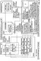
- the simulator 1 can be designed as a crane simulator, which includes a control stand 2 in the form of a crane operator's cab, which is essentially a "real" crane operator's cab, as used on a crane, for example a tower crane, a harbor crane or a maritime crane or mobile telescopic crane Can be found.
- a crane simulator which includes a control stand 2 in the form of a crane operator's cab, which is essentially a "real" crane operator's cab, as used on a crane, for example a tower crane, a harbor crane or a maritime crane or mobile telescopic crane Can be found.
- Said control station 2 can comprise, in a manner known per se, an operator's seat 21, for example in the form of an operator's chair 20, around which various input means 18 for entering control commands are arranged.
- Said input means 18 can for example have a joystick, a touchscreen, control levers, input keys and switches, rotary controls, slide controls and the like.
- a driver's cab wall 22 which can correspond to a cabin housing and can have window areas 23 that are glazed in real crane driver's cabs, but in the present case are colored in a certain color, for example coated with a green film, in order to Screen technology to be able to show a virtual machine environment, as will be explained.
- the control stand 2 is mounted on a movement platform 7, by means of which the control stand 2 can be moved in multiple axes.
- the movement platform 7 is advantageously designed to be movable in multiple axes, in particular tiltable or rotatable about all three spatial axes x, y and z and translationally displaceable along these axes.
- the movement axes x, y and z of the movement platform 7 are assigned actuators of a drive device 8, for example in the form of electric motors and / or hydraulic cylinders and / or hydraulic motors, in order to be able to move the control station 2 around or along the named axes.
- the drive device 8 is controlled by a movement control device 24, which can be implemented, for example, by an industrial PC.
- the mentioned movement control device 24 can in particular be part of a movement simulation module 10, by means of which crane movements and / or positions and / or alignments of crane components such as the boom or the tower and also twisting of structural components such as the boom or the tower depending on the respective at the control station 2 entered control commands can be determined. That said Movement simulation module 10 determines, so to speak, the effects of the input control commands on the crane to be simulated, ie which movements, positions, orientations and twists of the crane components would result on the crane to be simulated as a result of input control commands and outputs corresponding movement signals characterizing the variables mentioned.
- the mentioned movement simulation module 10 does not or does not completely determine the mentioned movement variables by calculation using a computer model, but rather uses actual hardware components in the form of drive and control components that perform actual movements and are simulated on a real crane with the corresponding hardware components.
- the movement simulation module 10 comprises at least the essential components of a crane control 25, as this can be implemented, for example, in the control cabinet of a crane.
- the named crane control 25 includes the frequency converters 15 of various crane drives, for example the slewing gear, the trolley and the hoisting gear.
- the mentioned crane control 25 can optionally include further control and / or power electronic components, in particular load monitoring components, work area restriction components, etc.
- the crane control 25 is communicatively connected to the control station 2 and its input means 18, so that the crane control 25 can further process the input control commands, the frequency converters 15 in particular controlling drive units 12, for example in the form of servo drives, depending on the input control commands.
- the control commands entered at the control station 2 are thus converted into real movements or drive torques and forces of the drive units 12.
- Said drive units 12 can be coupled to counter drive units 14, via which movement resistances can be connected to drive units 12 in order to be able to simulate real resistances such as lifting loads, wind forces, inertia or dynamic loads.
- the aforementioned counter drive units 14 can be controlled by the aforementioned industrial PC, which also implements the movement control device 24.
- the counter drive units 14 can be controlled using various specifications or programs, for example using prescribable lifting loads, prescribable wind programs or using predetermined functions or tables such as dynamic reactions when braking the trolley or the rotary movement.
- corresponding models, tables or functions can be stored in a memory module of the control device for controlling the counter drive units 14.
- the drive units 12 are assigned detection devices 13, for example in the form of rotary encoders or other position and / or movement sensors, by means of which movement or position signals are provided that characterize the actuating movements of the drive units 12.
- the movement simulation module 10 thus provides real sensor signals as movement parameters which, on the one hand, can be displayed on the control stand 2 and, on the other hand, can also be used for more extensive simulation functions.
- the movement simulation module 10 can include a computer unit 11, which in turn can be implemented by the aforementioned industrial PC, by means of which computer unit 11 as a function of the control station 2 input control commands and / or the emulated data generated by the data emulation device 19 or the sensor signals generated by the drive units 12 associated with the drive units 12, structural distortions are determined, in particular bending and torsion in the crane tower and in the crane boom, with the computer unit 11 entering the structural rigidity for this purpose used calculation model, as explained at the beginning.
- the movement control device 24 controls the drive device 8 of the movement platform 7 in order to move the control stand 2 and to simulate real crane operator cabin movements that would occur in a real crane if the corresponding control commands were entered.
- the mentioned movement data and possibly also the mentioned deformation data are used to take crane reactions into account in a virtual representation that is generated by a graphic simulation module 9 and displayed on a display device 3.
- the aforementioned virtual representation shows in particular the crane environment and the crane components visible therein, such as the crane boom and the load hook, and can essentially correspond to the image that a crane operator would see from the crane operator's cab.
- the aforementioned virtual representation can in this case correspond to a photo or film-like digital image, for example a pixel representation in several colors.
- a simplified graphic representation can also be provided, although a representation image that is as realistic as possible, photo- or film-like is preferred.
- the aforementioned virtual representation of the crane environment and the crane components visible therein is superimposed by a live image which shows real components from the control stand 2, in particular components such as the ones visible from the head of the simulator user in his direction of view Input means 18, the hands and forearms of the user and other components in the field of view.
- a camera 16 is advantageously provided, which can be designed as a head camera that can be worn on the head of the user and can have corresponding fastening and / or holding means for fastening on the head, for example in the form of a helmet camera. If the display device 3 is advantageously designed in the form of virtual reality glasses 4 that the user wears, the camera 16 can be integrated into these VR glasses.
- the camera 16 is advantageously designed as a stereoscopic camera in order to be able to provide stereoscopic images corresponding to the viewing axes of the two eyes of the user.
- the overlay device 17 for overlaying the virtual representation of the crane environment generated by the graphic simulation module 9 and the live image from the camera 16 can in particular include a color-based image processing module 26 that can work according to the so-called green screen technology.
- the named color-based image processing module 26 can recognize image areas in the live image of the camera 16 that have a specific color that differs from the remaining partial image areas, and then replace these image areas with the virtual representation from the simulation module 9.
- control station 2 can advantageously comprise a driver's cab wall 22 in which window areas 23 - for example corresponding to the viewing windows of a real crane driver's cab - are colored in a key color that differs from the remaining colors of the other components in the camera's field of view, such as the color of the window frames Input means 18 and the operator's clothing and skin color as clearly as possible, so that the live image recorded in the control stand 2 shows the mentioned colored areas in a specific color rendering, while all other picture areas are shown in different colors.
- window areas 23 - for example corresponding to the viewing windows of a real crane driver's cab - are colored in a key color that differs from the remaining colors of the other components in the camera's field of view, such as the color of the window frames Input means 18 and the operator's clothing and skin color as clearly as possible, so that the live image recorded in the control stand 2 shows the mentioned colored areas in a specific color rendering, while all other picture areas are shown in different colors.
- the live image areas or partial areas colored in the key color mentioned - for example green - are then replaced by the virtual representation of the machine environment and / or the machine components visible therein, which is generated by the graphic simulation module 9, so that the overlaid image or representation on the one hand shows the control station 2 of the simulator, its components and the limbs of the user located in the field of view of the live camera in real life as a live image and on the other hand shows the virtual representation of the machine environment and the machine components visible therein in the window areas 23 of the driver's cab wall 22 recorded by the live camera 16.
- Said virtual representation of the machine environment can advantageously be changed by the graphic simulation module 9 and adapted to various scenarios as a function of various data records that can be imported into the simulation module via an interface.
- planning data such as CAD data of a building to be manufactured and / or actual construction site data and / or image data, which reflect the actual state of a building or structure depending on the construction progress, can be made via a corresponding data interface, for example a CAD interface and / or an image data interface, are imported into the simulation module 9 and used by the simulation module 9 to generate or adapt the virtual representation of the machine environment according to the imported data record, in particular depending on the imported planning data and / or actual construction site data.
Landscapes
- Engineering & Computer Science (AREA)
- Mining & Mineral Resources (AREA)
- Civil Engineering (AREA)
- General Engineering & Computer Science (AREA)
- Structural Engineering (AREA)
- Mechanical Engineering (AREA)
- Theoretical Computer Science (AREA)
- Automation & Control Theory (AREA)
- Aviation & Aerospace Engineering (AREA)
- Educational Administration (AREA)
- Educational Technology (AREA)
- General Physics & Mathematics (AREA)
- Physics & Mathematics (AREA)
- Business, Economics & Management (AREA)
- Control And Safety Of Cranes (AREA)
- Processing Or Creating Images (AREA)
- Jib Cranes (AREA)
- Forklifts And Lifting Vehicles (AREA)
- Management, Administration, Business Operations System, And Electronic Commerce (AREA)
Claims (15)
- Simulateur pour une grue, un engin de construction ou un chariot de manutention, avec un poste de commande (2), qui présente au moins un moyen de saisie (18) pour saisir des instructions de commande, un module de simulation graphique (9) pour calculer une représentation virtuelle de l'environnement d'engin et/ou de composants d'engin visibles depuis le poste de commande (2), ainsi qu'avec un dispositif d'affichage (3) pour afficher la représentation virtuelle calculée, dans lequel un module de simulation de déplacement (10) est prévu pour définir des déplacements et/ou déformations de composants d'engin, tels que la flèche de grue ou des crochets de charge, en fonction des instructions de commande saisies et le module de simulation graphique (9) est réalisé pour calculer la représentation virtuelle en fonction des déplacements et/ou déformations définies, caractérisé en ce que le module de simulation de déplacement (10) comprend un système d'émulation de données (19) pour l'émulation de données de déplacement de l'engin à simuler, dans lequel ledit système d'émulation de données (19) comprend au moins une unité d'entraînement (12) pour exécuter des déplacements d'entraînement de réglage en fonction d'instructions de commande saisies sur le poste de commande (2), au moins une autre unité d'entraînement (14) pour fournir un contre-couple et/ou une contre-charge, laquelle autre unité d'entraînement (14) peut être couplée à l'au moins une unité d'entraînement (12), ainsi qu'un système de détection (13) pour détecter les déplacements de l'unité d'entraînement (12) et fournir un signal de déplacement et/ou de position, dans lequel ledit signal de déplacement et/ou de position reproduit le déplacement de réglage obtenu réellement et est utilisé en tant que signal de capteur dans la simulation ultérieure, et le dispositif de simulation graphique est réalisé pour générer la représentation virtuelle en tenant compte du déplacement d'entraînement de réglage exécuté.
- Simulateur selon la revendication précédente, dans lequel le module de simulation de déplacement (10) présente au moins un composant de commande de puissance, en particulier sous la forme d'un convertisseur de fréquence (15) pour piloter l'au moins une unité d'entraînement (12).
- Simulateur selon la revendication précédente, dans lequel le module de simulation de déplacement (10) comprend l'armoire de distribution et/ou l'unité de commande, qui correspondent à l'armoire de distribution et/ou à l'unité de commande de l'engin à simuler ou sont conformées à celles-ci.
- Simulateur selon le préambule de la revendication 1 ou selon l'une quelconque des revendications précédentes, dans lequel le poste de commande (2) est monté de manière mobile et un dispositif d'entraînement (8) est prévu pour déplacer le poste de commande (2) en fonction des déplacements et/ou déformations définis par le module de simulation de déplacement (10).
- Simulateur selon la revendication précédente, dans lequel le poste de commande (2) est monté de manière mobile sur plusieurs axes et le dispositif d'entraînement (8) présente plusieurs axes de déplacement (x, y, z), de préférence comprenant plusieurs axes de déplacement par rotation et/ou plusieurs axes de déplacement par translation, qui peuvent être actionnés en fonction d'instructions de commande saisies sur le poste de commande (2).
- Simulateur selon l'une quelconque des deux revendications précédentes, dans lequel le poste de commande (2) est monté sur une plate-forme de déplacement (7), dans laquelle le dispositif d'entraînement (8) est intégré.
- Simulateur selon le préambule de la revendication 1 ou selon l'une quelconque des revendications précédentes, dans lequel le module de simulation de déplacement (10) présente un système de définition pour définir des déformations de composants structurels de l'engin à simuler en fonction d'instructions de commande saisies sur le poste de commande (2), dans lequel ledit système de définition présente une unité de calcul (11) pour calculer les déformations à l'aide d'un modèle de déformation mémorisé des composants structurels.
- Simulateur selon la revendication précédente, dans lequel le module de simulation graphique (9) est réalisé pour générer la représentation virtuelle en fonction des déformations calculées des composants structurels et/ou un dispositif de commande est prévu pour piloter le dispositif d'entraînement (8) en fonction des déformations calculées des composants structurels.
- Simulateur selon le préambule de la revendication 1 ou selon l'une quelconque des revendications précédentes, dans lequel au moins une caméra (16) pour détecter des images en direct est prévue sur le poste de commande (2) et est associé à l'au moins un dispositif d'affichage (3) un dispositif de superposition (17), qui est prévu pour superposer sur le dispositif d'affichage (3) la représentation virtuelle générée par le module de simulation graphique (9) avec l'image en direct fournie par la caméra (16).
- Simulateur selon la revendication précédente, dans lequel la caméra (16) présente une fixation de tête pour porter la caméra sur la tête de l'utilisateur du simulateur et/ou est réalisée en tant que caméra portée sur la tête et/ou sur le casque, dans lequel la caméra (16) est réalisée en tant que caméra stéréoscopique pour fournir des images stéréoscopiques au moins approximativement dans la direction du regard de l'utilisateur du simulateur, dans lequel l'au moins un dispositif d'affichage (3) présente une fixation de tête destinée à être portée sur la tête de l'utilisateur de simulateur et/ou est réalisé en tant que lunettes d'affichage, en particulier sous la forme de lunettes de réalité virtuelle avec caméra intégrée (16).
- Simulateur selon la revendication 9 ou 10, dans lequel le poste de commande (2) comprend une paroi de cabine, dans laquelle des fenêtres d'inspection sont réalisées, dans lequel lesdites fenêtres d'inspection sont colorées en une couleur définie, dans lequel le module de simulation graphique (9) et/ou le système de superposition (17) présentent une unité de masquage sensible aux couleurs pour masquer la représentation virtuelle sur les surfaces d'image de l'image en direct fournie par la caméra (16), qui sont colorées dans la couleur définie susmentionnée.
- Simulateur selon le préambule de la revendication 1 ou selon l'une quelconque des revendications précédentes, dans lequel le module de simulation graphique (9) présente une interface de données pour insérer des données d'ouvrage de construction et/ou de site de construction et présente un système de traitement d'images pour générer et/ou adapter la représentation virtuelle de l'environnement de l'engin en fonction des données de site de construction et/ou d'ouvrage de construction insérées.
- Simulateur selon la revendication précédente, dans lequel ladite interface de données est une interface CAD et le système de traitement d'images est réalisé pour générer et/ou adapter la représentation virtuelle de l'environnement de l'engin en fonction des données CAD insérées par l'intermédiaire de l'interface CAD, et/ou est une interface de données d'image et le système de traitement d'image est prévu pour générer et/ou adapter la représentation virtuelle de l'environnement de l'engin en fonction des données d'image de préférence numériques insérées par l'intermédiaire de l'interface de données d'image.
- Utilisation d'un simulateur selon l'une quelconque des revendications précédentes en tant que système de commande à distance pour commander à distance une grue, un engin de construction ou un chariot de manutention.
- Système comprenant un simulateur (1), qui est réalisé selon l'une quelconque des revendications 1 - 13, ainsi qu'une grue, un engin de construction ou un chariot de manutention, dans lequel est prévue entre la grue, l'engin de construction et/ou le chariot de manutention d'une part et le simulateur (1) d'autre part une liaison de communication, par l'intermédiaire de laquelle des instructions de commande saisies sur le poste de commande (2) du simulateur (1) peuvent être transférées au système de commande de la grue, de l'engin de construction et/ou du chariot de manutention.
Applications Claiming Priority (2)
| Application Number | Priority Date | Filing Date | Title |
|---|---|---|---|
| DE102016000353.7A DE102016000353A1 (de) | 2016-01-14 | 2016-01-14 | Kran-, Baumaschinen- oder Flurförderzeug-Simulator |
| PCT/EP2017/000024 WO2017121636A1 (fr) | 2016-01-14 | 2017-01-10 | Simulateur de grues, de machines de chantier ou de chariots de manutention |
Publications (2)
| Publication Number | Publication Date |
|---|---|
| EP3381027A1 EP3381027A1 (fr) | 2018-10-03 |
| EP3381027B1 true EP3381027B1 (fr) | 2021-07-21 |
Family
ID=57838340
Family Applications (2)
| Application Number | Title | Priority Date | Filing Date |
|---|---|---|---|
| EP17700592.3A Active EP3381027B1 (fr) | 2016-01-14 | 2017-01-10 | Simulateur de grues, de machines de chantier ou de chariots de manutention |
| EP21197655.0A Pending EP3950558A1 (fr) | 2016-01-14 | 2017-04-07 | Dispositif de commande à distance pour grues, machines de construction et/ou chariots de manutention |
Family Applications After (1)
| Application Number | Title | Priority Date | Filing Date |
|---|---|---|---|
| EP21197655.0A Pending EP3950558A1 (fr) | 2016-01-14 | 2017-04-07 | Dispositif de commande à distance pour grues, machines de construction et/ou chariots de manutention |
Country Status (8)
| Country | Link |
|---|---|
| US (3) | US10968082B2 (fr) |
| EP (2) | EP3381027B1 (fr) |
| CN (2) | CN108701425B (fr) |
| BR (2) | BR112018013923A2 (fr) |
| DE (2) | DE102016000353A1 (fr) |
| ES (1) | ES2904634T3 (fr) |
| RU (3) | RU2730697C2 (fr) |
| WO (2) | WO2017121636A1 (fr) |
Families Citing this family (49)
| Publication number | Priority date | Publication date | Assignee | Title |
|---|---|---|---|---|
| JP6306552B2 (ja) * | 2015-10-13 | 2018-04-04 | 株式会社タダノ | 遠隔操作装置、及び案内システム |
| DE102016000353A1 (de) * | 2016-01-14 | 2017-07-20 | Liebherr-Components Biberach Gmbh | Kran-, Baumaschinen- oder Flurförderzeug-Simulator |
| DE102017112765A1 (de) * | 2017-06-09 | 2018-12-13 | Liebherr-Werk Biberach Gmbh | Verfahren und Vorrichtung zum Heben einer Last |
| CN107403580B (zh) * | 2017-07-20 | 2023-05-23 | 兰州安信铁路科技有限公司 | 一种铁路信号综合系统实验平台 |
| JP6985519B2 (ja) | 2017-09-26 | 2021-12-22 | パルフィンガー アクチエンゲゼルシャフトPalfinger Ag | 操作装置および操作装置を備えた貨物クレーン |
| JP7087475B2 (ja) * | 2018-03-09 | 2022-06-21 | 株式会社タダノ | 遠隔操作端末および遠隔操作端末を備える移動式クレーン |
| JP7206622B2 (ja) * | 2018-04-20 | 2023-01-18 | コベルコ建機株式会社 | 作業受発注システム、サーバ、及び作業受発注方法 |
| JP7143634B2 (ja) * | 2018-05-29 | 2022-09-29 | コベルコ建機株式会社 | 技能評価システム及び技能評価方法 |
| CN108510831A (zh) * | 2018-06-04 | 2018-09-07 | 上海振华重工(集团)股份有限公司 | 自动化桥吊远程操作模拟器 |
| JP7040304B2 (ja) * | 2018-06-12 | 2022-03-23 | コベルコ建機株式会社 | 施工管理システム |
| CN108877379A (zh) * | 2018-09-10 | 2018-11-23 | 苏州大成有方数据科技有限公司 | 一种活动式工程模拟器的自动控制系统 |
| CN109972674B (zh) * | 2019-03-04 | 2020-10-02 | 华中科技大学 | 基于自然交互的复杂施工环境下的无人挖掘系统及方法 |
| DE102019108689A1 (de) * | 2019-04-03 | 2020-10-08 | Liebherr-Werk Biberach Gmbh | Verfahren und Vorrichtung zum Steuern einer Materialumschlags- und/oder Baumaschine |
| JP2020170474A (ja) * | 2019-04-05 | 2020-10-15 | コベルコ建機株式会社 | スキル情報提示システム及びスキル情報提示方法 |
| JP7302244B2 (ja) * | 2019-04-05 | 2023-07-04 | コベルコ建機株式会社 | スキル情報提示システム及びスキル情報提示方法 |
| CN110555913B (zh) * | 2019-08-27 | 2023-04-14 | 正知(上海)智能技术有限公司 | 一种基于工业人机界面的虚拟成像方法及装置 |
| JP7415480B2 (ja) * | 2019-11-25 | 2024-01-17 | コベルコ建機株式会社 | 作業支援サーバおよび作業支援システム |
| JP7310595B2 (ja) * | 2019-12-24 | 2023-07-19 | コベルコ建機株式会社 | 作業支援サーバおよび作業支援システム |
| US11486115B2 (en) * | 2020-02-13 | 2022-11-01 | Caterpillar Inc. | Remote training system and method |
| CN111402559A (zh) * | 2020-02-28 | 2020-07-10 | 三一重型装备有限公司 | 遥控系统和采矿系统 |
| DE102020108592A1 (de) | 2020-03-27 | 2021-09-30 | Jungheinrich Aktiengesellschaft | Vorrichtung sowie Verfahren zum Fernsteuern eines Flurförderzeugs |
| US11595618B2 (en) | 2020-04-07 | 2023-02-28 | Caterpillar Inc. | Enhanced visibility system for work machines |
| CN111524414A (zh) * | 2020-04-22 | 2020-08-11 | 江苏桅杆电子科技有限公司 | 一种用于汽车雷达的电控模拟系统 |
| JP7484401B2 (ja) * | 2020-05-13 | 2024-05-16 | コベルコ建機株式会社 | 作業機械の遠隔操作支援システム |
| WO2021236658A1 (fr) | 2020-05-19 | 2021-11-25 | Boehringer Ingelheim International Gmbh | Molécules de liaison pour le traitement du cancer |
| US12019150B2 (en) * | 2020-09-25 | 2024-06-25 | Rohde & Schwarz Gmbh & Co. Kg | Radar target simulation system and radar target simulation method |
| CN112479037B (zh) * | 2020-12-01 | 2023-05-09 | 徐州重型机械有限公司 | 一种穿戴式监控系统、起重机及工程机械 |
| EP4033035B1 (fr) * | 2021-01-20 | 2026-02-25 | Volvo Autonomous Solutions AB | Système et procédé associé pour le fonctionnement à distance d'une machine de travail comprenant un outil |
| CN112764357A (zh) * | 2021-01-22 | 2021-05-07 | 郑州捷安高科股份有限公司 | 工程机械仿真方法、装置、设备及存储介质 |
| US12600608B2 (en) | 2021-03-04 | 2026-04-14 | The Raymond Corporation | Assistance systems and methods for a material handling vehicle |
| CN113192382A (zh) * | 2021-03-19 | 2021-07-30 | 徐州九鼎机电总厂 | 一种基于沉浸式人机交互的车辆机动性仿真系统及方法 |
| US11893902B1 (en) | 2021-05-11 | 2024-02-06 | Prabhu Swaminathan | Educational training system using mechanical models |
| US12353205B2 (en) | 2021-08-11 | 2025-07-08 | Doosan Bobcat North America, Inc. | Remote control for a power machine |
| WO2023122742A1 (fr) | 2021-12-22 | 2023-06-29 | Clark Equipment Company | Commande de multiples machines électriques |
| CN114327076B (zh) * | 2022-01-04 | 2024-08-13 | 上海三一重机股份有限公司 | 作业机械与作业环境的虚拟交互方法、装置及系统 |
| JP2024007313A (ja) | 2022-07-05 | 2024-01-18 | 吉谷土木株式会社 | 作付け支援方法と圃場作業支援システム等 |
| CN115376378B (zh) * | 2022-08-15 | 2024-11-19 | 杭州大杰智能传动科技有限公司 | 一种基于虚拟现实的塔式起重机操作方法 |
| US12559352B2 (en) | 2022-09-15 | 2026-02-24 | Olsbergs Electronics AB | Controller and system for simulation of crane operation |
| US12518476B2 (en) * | 2022-11-02 | 2026-01-06 | Adeia Guides Inc. | Systems and methods for emulating a user device in a virtual environment |
| JPWO2024135603A1 (fr) * | 2022-12-20 | 2024-06-27 | ||
| US20240412658A1 (en) * | 2023-06-06 | 2024-12-12 | Kyler Lemery | Virtual reality forklift simulator and methods of use thereof |
| CN116654779B (zh) * | 2023-06-07 | 2024-12-06 | 中建三局信息科技有限公司 | 一种塔式起重机的数字孪生方法及系统 |
| IT202300011913A1 (it) * | 2023-06-12 | 2024-12-12 | Merlo Project Srl | Veicolo sollevatore multifunzionale e relativo dispositivo di visualizzazione intelligente |
| JP2025003004A (ja) * | 2023-06-23 | 2025-01-09 | コベルコ建機株式会社 | 操作装置および操作システム |
| CN116768060A (zh) * | 2023-08-09 | 2023-09-19 | 浙江恒邦电气科技有限公司 | 一种双摄体感式塔机遥控操作系统 |
| WO2025156010A1 (fr) * | 2024-01-23 | 2025-07-31 | Molec Electrical Contractors Pty. Ltd. | Aide à l'entraînement de commande de véhicule ou de machine portable |
| WO2025181913A1 (fr) * | 2024-02-27 | 2025-09-04 | 日本電気株式会社 | Dispositif de création de plan de commande et procédé de création de plan de commande |
| WO2025181914A1 (fr) * | 2024-02-27 | 2025-09-04 | 日本電気株式会社 | Dispositif de création de plan de commande et procédé de création de plan de commande |
| CN118545613B (zh) * | 2024-07-30 | 2024-09-17 | 保利长大工程有限公司 | 基于视觉识别的料斗自动初定位系统 |
Family Cites Families (74)
| Publication number | Priority date | Publication date | Assignee | Title |
|---|---|---|---|---|
| US3557304A (en) * | 1967-10-24 | 1971-01-19 | Richard O Rue | Remote control flying system |
| US4884137A (en) * | 1986-07-10 | 1989-11-28 | Varo, Inc. | Head mounted video display and remote camera system |
| US20030224333A1 (en) * | 2002-05-31 | 2003-12-04 | Jan Vastvedt | Suspended Motion system simulation theater |
| US20060040239A1 (en) * | 2004-08-02 | 2006-02-23 | J. J. Keller & Associates, Inc. | Driving simulator having articial intelligence profiles, replay, hazards, and other features |
| US20060265664A1 (en) * | 2005-05-17 | 2006-11-23 | Hitachi, Ltd. | System, method and computer program product for user interface operations for ad-hoc sensor node tracking |
| US7848698B2 (en) * | 2005-07-22 | 2010-12-07 | Appareo Systems Llc | Flight training and synthetic flight simulation system and method |
| US8333592B2 (en) * | 2005-12-06 | 2012-12-18 | Andrew Warburton Swan | Video-captured model vehicle simulator |
| DE102006044086B4 (de) * | 2006-09-20 | 2013-05-29 | Audi Ag | System und Verfahren zur Simulation von Verkehrssituationen, insbesondere unfallkritischen Gefahrensituationen, sowie ein Fahrsimulator |
| US8139108B2 (en) * | 2007-01-31 | 2012-03-20 | Caterpillar Inc. | Simulation system implementing real-time machine data |
| US20080249756A1 (en) * | 2007-04-06 | 2008-10-09 | Pongsak Chaisuparasmikul | Method and system for integrating computer aided design and energy simulation |
| CN101046926A (zh) * | 2007-04-28 | 2007-10-03 | 武汉科技大学 | 一种起重机虚拟操纵系统 |
| CN101231790A (zh) * | 2007-12-20 | 2008-07-30 | 北京理工大学 | 基于多个固定摄像机的增强现实飞行模拟器 |
| TWI444939B (zh) * | 2008-01-10 | 2014-07-11 | Univ Nat Taiwan | 工程吊車之模擬系統及其方法 |
| CN201172591Y (zh) * | 2008-01-29 | 2008-12-31 | 黎峰 | 塔机远程智能操作装置 |
| WO2010047562A2 (fr) * | 2008-10-23 | 2010-04-29 | Oh Seung-Kug | Simulateur |
| US8195368B1 (en) * | 2008-11-07 | 2012-06-05 | The United States Of America As Represented By The Secretary Of The Navy | Coordinated control of two shipboard cranes for cargo transfer with ship motion compensation |
| CN101419756A (zh) * | 2008-11-24 | 2009-04-29 | 常州基腾电气有限公司 | 港口起重机模拟操作系统 |
| US9206589B2 (en) * | 2009-03-31 | 2015-12-08 | Caterpillar Inc. | System and method for controlling machines remotely |
| EP2280359A1 (fr) * | 2009-07-31 | 2011-02-02 | EADS Construcciones Aeronauticas, S.A. | Procédé de formation et système comprenant à l'aide de la réalité augmentée |
| CN101661676B (zh) * | 2009-09-16 | 2011-07-20 | 山东建筑大学 | 塔式起重机操作模拟培训系统 |
| DE102009045452B4 (de) * | 2009-10-07 | 2011-07-07 | Winter, York, 10629 | Anordnung und Verfahren zur Durchführung einer interaktiven Simulation sowie ein entsprechendes Computerprogramm und ein entsprechendes computerlesbares Speichermedium |
| JP5491516B2 (ja) * | 2009-10-19 | 2014-05-14 | 日立建機株式会社 | 作業機械 |
| BR112012013204A2 (pt) * | 2009-12-03 | 2016-03-01 | John Deere Forestry Oy | método para exibir uma área de trabalho, aparelho, produto de programa de computador armazenado em um meio legível por computador e executável em um dispositivo de processamento de dados, sistema e máquina florestal |
| BRPI0914277A2 (pt) * | 2009-12-11 | 2012-05-02 | Petroleo Brasileiro Sa | simulador de operação de guindastes |
| CN201796514U (zh) * | 2010-03-12 | 2011-04-13 | 中国人民解放军总后勤部建筑工程研究所 | 挖掘机模拟训练平台 |
| DE102010016113A1 (de) * | 2010-03-24 | 2011-09-29 | Krauss-Maffei Wegmann Gmbh & Co. Kg | Verfahren zur Ausbildung eines Besatzungsmitglieds eines insbesondere militärischen Fahrzeugs |
| US8909467B2 (en) * | 2010-06-07 | 2014-12-09 | Industry-Academic Cooperation Foundation, Yonsei University | Tower crane navigation system |
| DE102010034671A1 (de) * | 2010-08-18 | 2012-02-23 | Volkswagen Ag | Fahrzeugbremsanlage mit Pedalsimulator |
| DE102010035814B3 (de) * | 2010-08-30 | 2011-12-29 | Grenzebach Maschinenbau Gmbh | Vorrichtung und Verfahren zum Betrieb eines Flugsimulators mit besonderer Realitäts-Anmutung |
| DE202010014309U1 (de) * | 2010-10-14 | 2012-01-18 | Liebherr-Werk Ehingen Gmbh | Kran, insbesondere Raupen- oder Mobilkran |
| CN201864485U (zh) * | 2010-11-12 | 2011-06-15 | 卫华集团有限公司 | 起重机三维组态仿真控制系统 |
| US20140111648A1 (en) * | 2011-06-02 | 2014-04-24 | Hitachi Contruction Machinery Co., Ltd. | Device For Monitoring Area Around Working Machine |
| CN102360396A (zh) * | 2011-09-27 | 2012-02-22 | 浙江工业大学 | 一种基于Virtools的虚拟双梁桥式起重机的构建方法 |
| JP2013116773A (ja) * | 2011-12-01 | 2013-06-13 | Shimizu Corp | タワークレーンの遠隔操作システム |
| KR101220787B1 (ko) * | 2012-02-01 | 2013-01-09 | 씨제이포디플렉스 주식회사 | 4자유도 모션 장치 |
| DE102012004802A1 (de) * | 2012-03-09 | 2013-09-12 | Liebherr-Werk Nenzing Gmbh | Kransteuerung mit Aufteilung einer kinematisch beschränkten Größe des Hubwerks |
| US9598836B2 (en) * | 2012-03-29 | 2017-03-21 | Harnischfeger Technologies, Inc. | Overhead view system for a shovel |
| DE102012205291A1 (de) * | 2012-03-30 | 2013-10-17 | Siemens Aktiengesellschaft | Sicherstellen der Positioniergenauigkeit von C-Bogensystemen durch numerische Optimierung |
| US10162797B1 (en) * | 2012-04-13 | 2018-12-25 | Design Data Corporation | System for determining structural member liftability |
| DE102012216489A1 (de) | 2012-09-17 | 2014-03-20 | Terex Cranes Germany Gmbh | Verfahren zum Bedienen eines Fernsteuerungssystems sowie derartiges Fernsteuerungssystem |
| US10410124B1 (en) * | 2013-01-21 | 2019-09-10 | Link-Belt Cranes, L.P., Lllp | Display for displaying lifting capacity of a lifting machine and related methods |
| CN103150939B (zh) * | 2013-03-01 | 2014-11-19 | 北京交通大学 | 一种冗余驱动的六自由度运动模拟器 |
| JP6284302B2 (ja) * | 2013-04-02 | 2018-02-28 | 株式会社タダノ | ブームの伸縮パターン選択装置 |
| DE102013011818B4 (de) | 2013-07-15 | 2023-07-06 | Liebherr-Werk Nenzing Gmbh | Simulator für eine Arbeitsmaschine |
| KR101483106B1 (ko) * | 2013-07-31 | 2015-01-16 | 한국항공우주산업 주식회사 | 표시영상화면의 시점변경기능이 구비된 비행시뮬레이터장치 및 그 제어방법 |
| US20150321758A1 (en) * | 2013-08-31 | 2015-11-12 | II Peter Christopher Sarna | UAV deployment and control system |
| CN103531051A (zh) * | 2013-10-21 | 2014-01-22 | 武汉湾流新技术有限公司 | 一种起重机操作的虚拟现实训练方法及模拟器 |
| ITVR20130046U1 (it) * | 2013-10-25 | 2015-04-26 | Giovanni Nicola Lopreiato | Simulatore di volo trasportabile |
| MX363593B (es) * | 2014-02-14 | 2019-03-28 | Sandvik Mining & Construction Oy | Arreglo para iniciar un modo de operación remoto. |
| CN103794103B (zh) | 2014-02-26 | 2016-08-17 | 上海海事大学 | 一种便携式两通道港口起重机模拟器构建方法 |
| DE202014001801U1 (de) * | 2014-02-26 | 2015-05-27 | Liebherr-Components Biberach Gmbh | Kran |
| CN103871291A (zh) * | 2014-04-06 | 2014-06-18 | 门立山 | 一种学驾照用的驾驶模拟系统 |
| WO2015155845A1 (fr) * | 2014-04-09 | 2015-10-15 | 株式会社日立製作所 | Système de commande à distance pour machines de chantier |
| WO2015155878A1 (fr) * | 2014-04-11 | 2015-10-15 | 株式会社日立製作所 | Machine de travail télécommandée |
| US20150310758A1 (en) * | 2014-04-26 | 2015-10-29 | The Travelers Indemnity Company | Systems, methods, and apparatus for generating customized virtual reality experiences |
| US9741169B1 (en) * | 2014-05-20 | 2017-08-22 | Leap Motion, Inc. | Wearable augmented reality devices with object detection and tracking |
| CN103995478B (zh) * | 2014-05-30 | 2016-05-18 | 山东建筑大学 | 基于现实虚拟互动的模块化液压机械臂实验平台及方法 |
| US9227821B1 (en) * | 2014-07-31 | 2016-01-05 | Trimble Navigation Limited | Crane operation simulation |
| US20160035251A1 (en) * | 2014-07-31 | 2016-02-04 | Trimble Navigation Limited | Crane operator guidance |
| US9690375B2 (en) * | 2014-08-18 | 2017-06-27 | Universal City Studios Llc | Systems and methods for generating augmented and virtual reality images |
| CN204143671U (zh) * | 2014-09-15 | 2015-02-04 | 孙波 | 赛车模拟器 |
| DE102014218749A1 (de) * | 2014-09-18 | 2016-03-24 | Bayerische Motoren Werke Aktiengesellschaft | Unterstützung eines Bedieners einer Arbeitsmaschine mittels eines unbemannten Flugobjektes |
| US9446858B2 (en) * | 2014-09-18 | 2016-09-20 | Kevin Hess | Apparatus and methods for tethered aerial platform and system |
| WO2016053220A1 (fr) * | 2014-10-01 | 2016-04-07 | Turgay Gürbüz | Grue à tour commandée au sol dotée d'un système de caméra |
| CN104361781A (zh) * | 2014-11-25 | 2015-02-18 | 上海建工五建集团有限公司 | 塔机仿真模拟系统 |
| US10057534B2 (en) * | 2015-02-27 | 2018-08-21 | Badu Networks, Inc. | Hybrid modular device |
| US9685009B2 (en) * | 2015-04-01 | 2017-06-20 | Caterpillar Inc. | System and method for managing mixed fleet worksites using video and audio analytics |
| CN204557842U (zh) * | 2015-04-13 | 2015-08-12 | 庄荣发 | 驾驶操纵模拟室 |
| JP6496182B2 (ja) * | 2015-04-28 | 2019-04-03 | 株式会社小松製作所 | 施工計画システム |
| CN105185184B (zh) * | 2015-07-17 | 2018-06-12 | 北京大华旺达科技有限公司 | 一种六自由度并联动感平台 |
| DE102016000353A1 (de) * | 2016-01-14 | 2017-07-20 | Liebherr-Components Biberach Gmbh | Kran-, Baumaschinen- oder Flurförderzeug-Simulator |
| DE102016000351A1 (de) * | 2016-01-14 | 2017-07-20 | Liebherr-Werk Biberach Gmbh | Kran-, Baumaschinen- oder Flurförderzeug-Simulator |
| CN107466384A (zh) * | 2016-05-25 | 2017-12-12 | 深圳市大疆创新科技有限公司 | 一种追踪目标的方法及装置 |
| US10242562B2 (en) * | 2017-02-22 | 2019-03-26 | Thames Technology Holdings, Inc. | Control systems with modular configurable devices |
-
2016
- 2016-01-14 DE DE102016000353.7A patent/DE102016000353A1/de active Pending
- 2016-04-08 DE DE202016002295.5U patent/DE202016002295U1/de not_active Expired - Lifetime
-
2017
- 2017-01-10 CN CN201780006880.5A patent/CN108701425B/zh not_active Expired - Fee Related
- 2017-01-10 BR BR112018013923-8A patent/BR112018013923A2/pt not_active Application Discontinuation
- 2017-01-10 WO PCT/EP2017/000024 patent/WO2017121636A1/fr not_active Ceased
- 2017-01-10 EP EP17700592.3A patent/EP3381027B1/fr active Active
- 2017-01-10 RU RU2018128141A patent/RU2730697C2/ru active
- 2017-01-10 US US16/069,384 patent/US10968082B2/en active Active
- 2017-04-07 EP EP21197655.0A patent/EP3950558A1/fr active Pending
- 2017-04-07 WO PCT/EP2017/000460 patent/WO2017174205A2/fr not_active Ceased
- 2017-04-07 CN CN201780024872.3A patent/CN109311639B/zh active Active
- 2017-04-07 RU RU2021100284A patent/RU2021100284A/ru unknown
- 2017-04-07 ES ES17721522T patent/ES2904634T3/es active Active
- 2017-04-07 BR BR112018070471A patent/BR112018070471A2/pt not_active Application Discontinuation
- 2017-04-07 RU RU2018138301A patent/RU2741456C2/ru active
-
2018
- 2018-10-09 US US16/155,534 patent/US10850949B2/en active Active
-
2021
- 2021-01-19 US US17/152,251 patent/US11634306B2/en active Active
Non-Patent Citations (1)
| Title |
|---|
| None * |
Also Published As
| Publication number | Publication date |
|---|---|
| WO2017174205A2 (fr) | 2017-10-12 |
| US20190039862A1 (en) | 2019-02-07 |
| ES2904634T3 (es) | 2022-04-05 |
| CN108701425A (zh) | 2018-10-23 |
| WO2017174205A3 (fr) | 2018-01-25 |
| EP3950558A1 (fr) | 2022-02-09 |
| RU2018138301A3 (fr) | 2020-09-17 |
| US20210139293A1 (en) | 2021-05-13 |
| EP3381027A1 (fr) | 2018-10-03 |
| DE102016000353A1 (de) | 2017-07-20 |
| US10850949B2 (en) | 2020-12-01 |
| RU2021100284A (ru) | 2021-02-03 |
| BR112018013923A2 (pt) | 2018-12-11 |
| CN109311639A (zh) | 2019-02-05 |
| CN108701425B (zh) | 2021-10-19 |
| US10968082B2 (en) | 2021-04-06 |
| BR112018070471A2 (pt) | 2019-01-29 |
| RU2018138301A (ru) | 2020-05-12 |
| RU2018128141A (ru) | 2020-02-03 |
| US20190019429A1 (en) | 2019-01-17 |
| WO2017121636A1 (fr) | 2017-07-20 |
| DE202016002295U1 (de) | 2017-04-20 |
| RU2018128141A3 (fr) | 2020-05-26 |
| US11634306B2 (en) | 2023-04-25 |
| RU2741456C2 (ru) | 2021-01-26 |
| CN109311639B (zh) | 2021-01-12 |
| RU2730697C2 (ru) | 2020-08-25 |
Similar Documents
| Publication | Publication Date | Title |
|---|---|---|
| EP3381027B1 (fr) | Simulateur de grues, de machines de chantier ou de chariots de manutention | |
| EP3403253B1 (fr) | Simulateur de grues | |
| EP3504148B1 (fr) | Dispositif de télécommande pour grue, engin de chantier et/ou chariot élévateur, et système comprenant ledit dispositif de télécommande et une grue, un engin de chantier et/ou un chariot élévateur | |
| EP3437036B1 (fr) | Procédé et dispositif pour planifier et/ou commander et/ou simuler le fonctionnement d'un engin de chantier | |
| EP3904984B1 (fr) | Procédé d'interaction immersive homme-machine | |
| DE102013011818B4 (de) | Simulator für eine Arbeitsmaschine | |
| EP3408210B1 (fr) | Dispositif de commande à distance d'une grue, d'un engin de chantier et/ou d'un chariot de manutention | |
| DE102018109326B4 (de) | Mehrgliedrige aktuierte Kinematik, vorzugsweise Roboter, besonders vorzugsweise Knickarmroboter | |
| EP1700175A1 (fr) | Dispositif et procede de programmation d'un robot industriel | |
| DE102018201589A1 (de) | Verfahren zur Programmierung der Steuerung eines Industrieroboters, Verfahren zum Betreiben eines Industrieroboters, Programmiervorrichtung sowie Industrierobotersystem mit einer solchen Programmiervorrichtung | |
| DE102005003513A1 (de) | Mobile haptische Schnittstelle | |
| DE102022127203A1 (de) | Verfahren und Anordnung zum Betrieb einer Tiefbaumaschine |
Legal Events
| Date | Code | Title | Description |
|---|---|---|---|
| STAA | Information on the status of an ep patent application or granted ep patent |
Free format text: STATUS: UNKNOWN |
|
| STAA | Information on the status of an ep patent application or granted ep patent |
Free format text: STATUS: THE INTERNATIONAL PUBLICATION HAS BEEN MADE |
|
| PUAI | Public reference made under article 153(3) epc to a published international application that has entered the european phase |
Free format text: ORIGINAL CODE: 0009012 |
|
| STAA | Information on the status of an ep patent application or granted ep patent |
Free format text: STATUS: REQUEST FOR EXAMINATION WAS MADE |
|
| 17P | Request for examination filed |
Effective date: 20180628 |
|
| AK | Designated contracting states |
Kind code of ref document: A1 Designated state(s): AL AT BE BG CH CY CZ DE DK EE ES FI FR GB GR HR HU IE IS IT LI LT LU LV MC MK MT NL NO PL PT RO RS SE SI SK SM TR |
|
| AX | Request for extension of the european patent |
Extension state: BA ME |
|
| RIN1 | Information on inventor provided before grant (corrected) |
Inventor name: BRANDT, SVEN Inventor name: STEIB, THOMAS Inventor name: RESCH, JUERGEN Inventor name: PALBERG, MICHAEL |
|
| DAV | Request for validation of the european patent (deleted) | ||
| DAX | Request for extension of the european patent (deleted) | ||
| STAA | Information on the status of an ep patent application or granted ep patent |
Free format text: STATUS: EXAMINATION IS IN PROGRESS |
|
| 17Q | First examination report despatched |
Effective date: 20191219 |
|
| GRAP | Despatch of communication of intention to grant a patent |
Free format text: ORIGINAL CODE: EPIDOSNIGR1 |
|
| STAA | Information on the status of an ep patent application or granted ep patent |
Free format text: STATUS: GRANT OF PATENT IS INTENDED |
|
| RIC1 | Information provided on ipc code assigned before grant |
Ipc: B66C 13/54 20060101ALI20210120BHEP Ipc: G09B 9/05 20060101AFI20210120BHEP Ipc: B66C 13/40 20060101ALI20210120BHEP Ipc: B66C 13/46 20060101ALI20210120BHEP Ipc: E02F 9/16 20060101ALI20210120BHEP Ipc: E02F 9/26 20060101ALI20210120BHEP Ipc: E02F 9/20 20060101ALI20210120BHEP |
|
| INTG | Intention to grant announced |
Effective date: 20210210 |
|
| GRAS | Grant fee paid |
Free format text: ORIGINAL CODE: EPIDOSNIGR3 |
|
| GRAA | (expected) grant |
Free format text: ORIGINAL CODE: 0009210 |
|
| STAA | Information on the status of an ep patent application or granted ep patent |
Free format text: STATUS: THE PATENT HAS BEEN GRANTED |
|
| AK | Designated contracting states |
Kind code of ref document: B1 Designated state(s): AL AT BE BG CH CY CZ DE DK EE ES FI FR GB GR HR HU IE IS IT LI LT LU LV MC MK MT NL NO PL PT RO RS SE SI SK SM TR |
|
| REG | Reference to a national code |
Ref country code: GB Ref legal event code: FG4D Free format text: NOT ENGLISH |
|
| REG | Reference to a national code |
Ref country code: CH Ref legal event code: EP |
|
| REG | Reference to a national code |
Ref country code: DE Ref legal event code: R096 Ref document number: 502017010953 Country of ref document: DE |
|
| REG | Reference to a national code |
Ref country code: AT Ref legal event code: REF Ref document number: 1413307 Country of ref document: AT Kind code of ref document: T Effective date: 20210815 |
|
| REG | Reference to a national code |
Ref country code: IE Ref legal event code: FG4D Free format text: LANGUAGE OF EP DOCUMENT: GERMAN |
|
| REG | Reference to a national code |
Ref country code: LT Ref legal event code: MG9D |
|
| REG | Reference to a national code |
Ref country code: NL Ref legal event code: MP Effective date: 20210721 |
|
| PG25 | Lapsed in a contracting state [announced via postgrant information from national office to epo] |
Ref country code: BG Free format text: LAPSE BECAUSE OF FAILURE TO SUBMIT A TRANSLATION OF THE DESCRIPTION OR TO PAY THE FEE WITHIN THE PRESCRIBED TIME-LIMIT Effective date: 20211021 Ref country code: LT Free format text: LAPSE BECAUSE OF FAILURE TO SUBMIT A TRANSLATION OF THE DESCRIPTION OR TO PAY THE FEE WITHIN THE PRESCRIBED TIME-LIMIT Effective date: 20210721 Ref country code: ES Free format text: LAPSE BECAUSE OF FAILURE TO SUBMIT A TRANSLATION OF THE DESCRIPTION OR TO PAY THE FEE WITHIN THE PRESCRIBED TIME-LIMIT Effective date: 20210721 Ref country code: FI Free format text: LAPSE BECAUSE OF FAILURE TO SUBMIT A TRANSLATION OF THE DESCRIPTION OR TO PAY THE FEE WITHIN THE PRESCRIBED TIME-LIMIT Effective date: 20210721 Ref country code: NL Free format text: LAPSE BECAUSE OF FAILURE TO SUBMIT A TRANSLATION OF THE DESCRIPTION OR TO PAY THE FEE WITHIN THE PRESCRIBED TIME-LIMIT Effective date: 20210721 Ref country code: NO Free format text: LAPSE BECAUSE OF FAILURE TO SUBMIT A TRANSLATION OF THE DESCRIPTION OR TO PAY THE FEE WITHIN THE PRESCRIBED TIME-LIMIT Effective date: 20211021 Ref country code: PT Free format text: LAPSE BECAUSE OF FAILURE TO SUBMIT A TRANSLATION OF THE DESCRIPTION OR TO PAY THE FEE WITHIN THE PRESCRIBED TIME-LIMIT Effective date: 20211122 Ref country code: HR Free format text: LAPSE BECAUSE OF FAILURE TO SUBMIT A TRANSLATION OF THE DESCRIPTION OR TO PAY THE FEE WITHIN THE PRESCRIBED TIME-LIMIT Effective date: 20210721 Ref country code: RS Free format text: LAPSE BECAUSE OF FAILURE TO SUBMIT A TRANSLATION OF THE DESCRIPTION OR TO PAY THE FEE WITHIN THE PRESCRIBED TIME-LIMIT Effective date: 20210721 Ref country code: SE Free format text: LAPSE BECAUSE OF FAILURE TO SUBMIT A TRANSLATION OF THE DESCRIPTION OR TO PAY THE FEE WITHIN THE PRESCRIBED TIME-LIMIT Effective date: 20210721 |
|
| PG25 | Lapsed in a contracting state [announced via postgrant information from national office to epo] |
Ref country code: PL Free format text: LAPSE BECAUSE OF FAILURE TO SUBMIT A TRANSLATION OF THE DESCRIPTION OR TO PAY THE FEE WITHIN THE PRESCRIBED TIME-LIMIT Effective date: 20210721 Ref country code: LV Free format text: LAPSE BECAUSE OF FAILURE TO SUBMIT A TRANSLATION OF THE DESCRIPTION OR TO PAY THE FEE WITHIN THE PRESCRIBED TIME-LIMIT Effective date: 20210721 Ref country code: GR Free format text: LAPSE BECAUSE OF FAILURE TO SUBMIT A TRANSLATION OF THE DESCRIPTION OR TO PAY THE FEE WITHIN THE PRESCRIBED TIME-LIMIT Effective date: 20211022 |
|
| REG | Reference to a national code |
Ref country code: DE Ref legal event code: R097 Ref document number: 502017010953 Country of ref document: DE |
|
| PG25 | Lapsed in a contracting state [announced via postgrant information from national office to epo] |
Ref country code: DK Free format text: LAPSE BECAUSE OF FAILURE TO SUBMIT A TRANSLATION OF THE DESCRIPTION OR TO PAY THE FEE WITHIN THE PRESCRIBED TIME-LIMIT Effective date: 20210721 |
|
| PLBE | No opposition filed within time limit |
Free format text: ORIGINAL CODE: 0009261 |
|
| STAA | Information on the status of an ep patent application or granted ep patent |
Free format text: STATUS: NO OPPOSITION FILED WITHIN TIME LIMIT |
|
| PG25 | Lapsed in a contracting state [announced via postgrant information from national office to epo] |
Ref country code: SM Free format text: LAPSE BECAUSE OF FAILURE TO SUBMIT A TRANSLATION OF THE DESCRIPTION OR TO PAY THE FEE WITHIN THE PRESCRIBED TIME-LIMIT Effective date: 20210721 Ref country code: SK Free format text: LAPSE BECAUSE OF FAILURE TO SUBMIT A TRANSLATION OF THE DESCRIPTION OR TO PAY THE FEE WITHIN THE PRESCRIBED TIME-LIMIT Effective date: 20210721 Ref country code: RO Free format text: LAPSE BECAUSE OF FAILURE TO SUBMIT A TRANSLATION OF THE DESCRIPTION OR TO PAY THE FEE WITHIN THE PRESCRIBED TIME-LIMIT Effective date: 20210721 Ref country code: EE Free format text: LAPSE BECAUSE OF FAILURE TO SUBMIT A TRANSLATION OF THE DESCRIPTION OR TO PAY THE FEE WITHIN THE PRESCRIBED TIME-LIMIT Effective date: 20210721 Ref country code: CZ Free format text: LAPSE BECAUSE OF FAILURE TO SUBMIT A TRANSLATION OF THE DESCRIPTION OR TO PAY THE FEE WITHIN THE PRESCRIBED TIME-LIMIT Effective date: 20210721 Ref country code: AL Free format text: LAPSE BECAUSE OF FAILURE TO SUBMIT A TRANSLATION OF THE DESCRIPTION OR TO PAY THE FEE WITHIN THE PRESCRIBED TIME-LIMIT Effective date: 20210721 |
|
| 26N | No opposition filed |
Effective date: 20220422 |
|
| PG25 | Lapsed in a contracting state [announced via postgrant information from national office to epo] |
Ref country code: IT Free format text: LAPSE BECAUSE OF FAILURE TO SUBMIT A TRANSLATION OF THE DESCRIPTION OR TO PAY THE FEE WITHIN THE PRESCRIBED TIME-LIMIT Effective date: 20210721 |
|
| PG25 | Lapsed in a contracting state [announced via postgrant information from national office to epo] |
Ref country code: MC Free format text: LAPSE BECAUSE OF FAILURE TO SUBMIT A TRANSLATION OF THE DESCRIPTION OR TO PAY THE FEE WITHIN THE PRESCRIBED TIME-LIMIT Effective date: 20210721 |
|
| GBPC | Gb: european patent ceased through non-payment of renewal fee |
Effective date: 20220110 |
|
| REG | Reference to a national code |
Ref country code: BE Ref legal event code: MM Effective date: 20220131 |
|
| PG25 | Lapsed in a contracting state [announced via postgrant information from national office to epo] |
Ref country code: LU Free format text: LAPSE BECAUSE OF NON-PAYMENT OF DUE FEES Effective date: 20220110 Ref country code: GB Free format text: LAPSE BECAUSE OF NON-PAYMENT OF DUE FEES Effective date: 20220110 |
|
| REG | Reference to a national code |
Ref country code: DE Ref legal event code: R081 Ref document number: 502017010953 Country of ref document: DE Owner name: LIEBHERR-WERK BIBERACH GMBH, DE Free format text: FORMER OWNER: LIEBHERR-COMPONENTS BIBERACH GMBH, 88400 BIBERACH, DE |
|
| PG25 | Lapsed in a contracting state [announced via postgrant information from national office to epo] |
Ref country code: BE Free format text: LAPSE BECAUSE OF NON-PAYMENT OF DUE FEES Effective date: 20220131 |
|
| REG | Reference to a national code |
Ref country code: AT Ref legal event code: PC Ref document number: 1413307 Country of ref document: AT Kind code of ref document: T Owner name: LIEBHERR-WERK BIBERACH GMBH, DE Effective date: 20221018 |
|
| PG25 | Lapsed in a contracting state [announced via postgrant information from national office to epo] |
Ref country code: IE Free format text: LAPSE BECAUSE OF NON-PAYMENT OF DUE FEES Effective date: 20220110 |
|
| P01 | Opt-out of the competence of the unified patent court (upc) registered |
Effective date: 20230630 |
|
| P02 | Opt-out of the competence of the unified patent court (upc) changed |
Effective date: 20230906 |
|
| PG25 | Lapsed in a contracting state [announced via postgrant information from national office to epo] |
Ref country code: HU Free format text: LAPSE BECAUSE OF FAILURE TO SUBMIT A TRANSLATION OF THE DESCRIPTION OR TO PAY THE FEE WITHIN THE PRESCRIBED TIME-LIMIT; INVALID AB INITIO Effective date: 20170110 |
|
| PG25 | Lapsed in a contracting state [announced via postgrant information from national office to epo] |
Ref country code: MK Free format text: LAPSE BECAUSE OF FAILURE TO SUBMIT A TRANSLATION OF THE DESCRIPTION OR TO PAY THE FEE WITHIN THE PRESCRIBED TIME-LIMIT Effective date: 20210721 Ref country code: CY Free format text: LAPSE BECAUSE OF FAILURE TO SUBMIT A TRANSLATION OF THE DESCRIPTION OR TO PAY THE FEE WITHIN THE PRESCRIBED TIME-LIMIT Effective date: 20210721 |
|
| PG25 | Lapsed in a contracting state [announced via postgrant information from national office to epo] |
Ref country code: TR Free format text: LAPSE BECAUSE OF FAILURE TO SUBMIT A TRANSLATION OF THE DESCRIPTION OR TO PAY THE FEE WITHIN THE PRESCRIBED TIME-LIMIT Effective date: 20210721 |
|
| PG25 | Lapsed in a contracting state [announced via postgrant information from national office to epo] |
Ref country code: MT Free format text: LAPSE BECAUSE OF FAILURE TO SUBMIT A TRANSLATION OF THE DESCRIPTION OR TO PAY THE FEE WITHIN THE PRESCRIBED TIME-LIMIT Effective date: 20210721 |
|
| REG | Reference to a national code |
Ref country code: CH Ref legal event code: U11 Free format text: ST27 STATUS EVENT CODE: U-0-0-U10-U11 (AS PROVIDED BY THE NATIONAL OFFICE) Effective date: 20260201 |
|
| PGFP | Annual fee paid to national office [announced via postgrant information from national office to epo] |
Ref country code: DE Payment date: 20260203 Year of fee payment: 10 |
|
| PGFP | Annual fee paid to national office [announced via postgrant information from national office to epo] |
Ref country code: AT Payment date: 20260115 Year of fee payment: 10 |
|
| PGFP | Annual fee paid to national office [announced via postgrant information from national office to epo] |
Ref country code: FR Payment date: 20260125 Year of fee payment: 10 |
|
| PGFP | Annual fee paid to national office [announced via postgrant information from national office to epo] |
Ref country code: CH Payment date: 20260201 Year of fee payment: 10 |