EP3381328A1 - Caisse pour marchandise de détail et procédé de livraison et de stockage des marchandise de détail dans une caisse pour marchandise de détail - Google Patents
Caisse pour marchandise de détail et procédé de livraison et de stockage des marchandise de détail dans une caisse pour marchandise de détail Download PDFInfo
- Publication number
- EP3381328A1 EP3381328A1 EP18161726.7A EP18161726A EP3381328A1 EP 3381328 A1 EP3381328 A1 EP 3381328A1 EP 18161726 A EP18161726 A EP 18161726A EP 3381328 A1 EP3381328 A1 EP 3381328A1
- Authority
- EP
- European Patent Office
- Prior art keywords
- holder
- piece goods
- cargo
- transfer
- flap
- Prior art date
- Legal status (The legal status is an assumption and is not a legal conclusion. Google has not performed a legal analysis and makes no representation as to the accuracy of the status listed.)
- Granted
Links
Images





Classifications
-
- B—PERFORMING OPERATIONS; TRANSPORTING
- B65—CONVEYING; PACKING; STORING; HANDLING THIN OR FILAMENTARY MATERIAL
- B65G—TRANSPORT OR STORAGE DEVICES, e.g. CONVEYORS FOR LOADING OR TIPPING, SHOP CONVEYOR SYSTEMS OR PNEUMATIC TUBE CONVEYORS
- B65G1/00—Storing articles, individually or in orderly arrangement, in warehouses or magazines
- B65G1/02—Storage devices
- B65G1/04—Storage devices mechanical
- B65G1/0407—Storage devices mechanical using stacker cranes
- B65G1/0435—Storage devices mechanical using stacker cranes with pulling or pushing means on either stacking crane or stacking area
-
- A—HUMAN NECESSITIES
- A47—FURNITURE; DOMESTIC ARTICLES OR APPLIANCES; COFFEE MILLS; SPICE MILLS; SUCTION CLEANERS IN GENERAL
- A47B—TABLES; DESKS; OFFICE FURNITURE; CABINETS; DRAWERS; GENERAL DETAILS OF FURNITURE
- A47B96/00—Details of cabinets, racks or shelf units not covered by a single one of groups A47B43/00 - A47B95/00; General details of furniture
- A47B96/16—Drawers or movable shelves coupled to doors
-
- B—PERFORMING OPERATIONS; TRANSPORTING
- B60—VEHICLES IN GENERAL
- B60P—VEHICLES ADAPTED FOR LOAD TRANSPORTATION OR TO TRANSPORT, TO CARRY, OR TO COMPRISE SPECIAL LOADS OR OBJECTS
- B60P1/00—Vehicles predominantly for transporting loads and modified to facilitate loading, consolidating the load, or unloading
- B60P1/44—Vehicles predominantly for transporting loads and modified to facilitate loading, consolidating the load, or unloading having a loading platform thereon raising the load to the level of the load-transporting element
- B60P1/4471—General means for controlling movements of the loading platform, e.g. hydraulic systems
-
- B—PERFORMING OPERATIONS; TRANSPORTING
- B60—VEHICLES IN GENERAL
- B60P—VEHICLES ADAPTED FOR LOAD TRANSPORTATION OR TO TRANSPORT, TO CARRY, OR TO COMPRISE SPECIAL LOADS OR OBJECTS
- B60P3/00—Vehicles adapted to transport, to carry or to comprise special loads or objects
- B60P3/007—Vehicles adapted to transport, to carry or to comprise special loads or objects for delivery of small articles, e.g. milk, frozen articles
-
- B—PERFORMING OPERATIONS; TRANSPORTING
- B65—CONVEYING; PACKING; STORING; HANDLING THIN OR FILAMENTARY MATERIAL
- B65G—TRANSPORT OR STORAGE DEVICES, e.g. CONVEYORS FOR LOADING OR TIPPING, SHOP CONVEYOR SYSTEMS OR PNEUMATIC TUBE CONVEYORS
- B65G1/00—Storing articles, individually or in orderly arrangement, in warehouses or magazines
- B65G1/02—Storage devices
- B65G1/04—Storage devices mechanical
-
- B—PERFORMING OPERATIONS; TRANSPORTING
- B65—CONVEYING; PACKING; STORING; HANDLING THIN OR FILAMENTARY MATERIAL
- B65G—TRANSPORT OR STORAGE DEVICES, e.g. CONVEYORS FOR LOADING OR TIPPING, SHOP CONVEYOR SYSTEMS OR PNEUMATIC TUBE CONVEYORS
- B65G1/00—Storing articles, individually or in orderly arrangement, in warehouses or magazines
- B65G1/02—Storage devices
- B65G1/04—Storage devices mechanical
- B65G1/0407—Storage devices mechanical using stacker cranes
- B65G1/0421—Storage devices mechanical using stacker cranes with control for stacker crane operations
-
- G—PHYSICS
- G07—CHECKING-DEVICES
- G07F—COIN-FREED OR LIKE APPARATUS
- G07F11/00—Coin-freed apparatus for dispensing, or the like, discrete articles
- G07F11/46—Coin-freed apparatus for dispensing, or the like, discrete articles from movable storage containers or supports
- G07F11/60—Coin-freed apparatus for dispensing, or the like, discrete articles from movable storage containers or supports the storage containers or supports being rectilinearly movable
Definitions
- the invention relates to a cargo box, with at least one cargo compartment for receiving at least one piece goods, wherein the at least one cargo compartment at least one of a storage position for storing the at least one cargo in the cargo compartment in an at least partially outside of the cargo compartment arranged transfer position for transferring the cargo of the Piece goods box and / or is associated with the piece goods box adjustable holder and wherein the holder has at least in the transfer position two, in particular lateral holding areas for at least indirectly holding the at least one piece goods at least in the transfer position. Furthermore, the invention relates to a method for transferring and storing piece goods in such a cargo box.
- Piece goods boxes with at least one cargo compartment for receiving at least one piece goods are already known in different configurations.
- the corresponding cargo compartment is opened by a user who then manually loads a cargo in the cargo compartment or takes out of the cargo compartment.
- the present invention is therefore based on the object, the general cargo box and the method of the aforementioned and previously explained in such a way and further develop that the handling of piece goods for loading, interim storage and removal of piece goods in piece goods chambers of general cargo more efficiently and inexpensively can.
- a cargo box according to the preamble of claim 1, characterized in that in the transfer position between the holding portions of the at least one holder at least one in the horizontal direction from outside the at least one cargo compartment accessible and outside the cargo compartment is arranged free space.
- the transfer and / or transfer of cargo to the cargo compartment and / or from the cargo chamber can be done by machine. It is therefore no longer necessarily an operator required.
- the mechanical transfer and / or takeover of parcels can be done by means of a transfer device that can be moved when passing or taking over the piece goods through the free space.
- the transfer device is preferably designed similar to an arm that can carry piece goods directly or indirectly. If the transfer device carries the piece goods directly, then the parcel lies, for example, on the transfer device, while the transfer device, the parcel only carries indirectly when the transfer device carries a tray or a container on which or in which the parcel is placed.
- the transfer device can take the shipment, the tray or the container from the holder to transport the shipment, for example, in a vehicle and intermediately store there.
- the transfer device moves from the bottom to the top through the space between the holding areas, in particular pivoted, is.
- the consignment, the tray or the container can then, if necessary, positively, in particular in the direction of gravity of the transfer device are taken over, for example, to transfer the consignment, the tray or the container to a vehicle.
- the consignment can thus be stored in the general cargo compartment, for example, until a vehicle arrives and takes over the consignment and then takes it with it.
- the shipment can then be delivered in a desired manner at another location.
- a piece goods which is supplied as needed by a vehicle, passed to the cargo compartment and it is also required, as delivered. Then the transfer device will hold a piece goods, a tray or a container and in particular be moved from top to bottom through the space between the holding portions of the holder. In this way, a positive connection arises at least in the direction of gravity between the shipment, the tray or the container so that selbiger is lifted from the transfer device. In other words, the transfer device can be pulled down through the space while leaving the shipment with or without tray or container.
- the transfer device can be mounted on a vehicle.
- the transfer device is then carried along with the vehicle as well as the acquired and / or the general cargo to be transferred.
- the transfer device may also be from the vehicle be pressed off, be it manually or automatically. For example, it is no longer necessary for an operator to get out of the vehicle and to manually load the piece goods into the piece goods box and / or remove them manually from the piece goods box. This can be accomplished, for example, by the driver of the vehicle with the aid of the transfer device without the driver having to leave the vehicle.
- vehicle can be understood very broadly in the present case. Although it is for the sake of simplicity, preferably motor-driven vehicles meant, but also not motor-driven vehicles in question, which are moved, for example, manually or by another motor-driven vehicle. Especially in the case of motor-driven vehicles, these can be driven or controlled by a driver. However, it may also be completely or partially autonomously driving vehicles that can completely or partially dispense with a driver. In this case, for example, offer so-called land drones, which are unmanned autonomously driving over land vehicles. These can be much smaller than manned land vehicles, but this is not required.
- general cargo is basically understood to mean articles which can be transported in one piece, and in particular at manageable expense.
- the piece goods are therefore preferably individual items.
- a container such as a box, a loaded pallet, a roll or a barrel can be understood.
- a container containing bulk material, liquid or gas is also general cargo.
- a piece goods can also be a specific good or container as well as a repackaged goods or containers. Repackaged goods or general cargo are also referred to as packages.
- the size and weight of piece goods where due to the size and / or weight of the piece goods the piece goods can not be transported without further notice.
- these may in particular be piece goods whose maximum dimension is less than 3 m, preferably less than 2 m, in particular less than 1 m and / or whose maximum volume is less than 2 m 3 , preferably less than 1 m 3 , in particular less than 0.5 m 3 , is.
- an upper limit of the weight may be 100 kg, preferably 10 kg, in particular 1 kg.
- the piece goods can be, for example, everyday items such as consumables or food or technical items and equipment.
- piece goods can also be consignments which are typically handed over to specific addressees at certain locations, deposited for specific addressees or delivered to specific addressees.
- Regularly shipments are preferably represent smaller and lighter cargo.
- Shipments can be distributed for example with a parcel service, an express service or a courier service.
- shipments are often packages, so packaged cargo.
- the shipments are preferably letter items, parcels and / or print products.
- Package parcels also include parcels, while print products can also be leaflets, brochures and magazines. In addition to letters, postcards are also among the correspondence.
- the piece goods box for the transfer and storage of general cargo preferably a mailing box for the transfer and storage of shipments.
- a mailing box also preferably has mailing chambers for receiving at least one mail item.
- the invention can play its advantages in particular in connection with the shipment handling, which in the present consignments can be understood as possible types of general cargo.
- the shipments are mail items to be delivered by a postal company, which may be referred to as mail.
- the shipment handling can also be carried out by at least one parcel service, express service or courier service.
- the shipments are letter items, parcels and / or print products.
- Package parcels also include parcels, while print products can also be leaflets, brochures and magazines.
- a letter can be next to a letter and a postcard.
- the at least one free space is provided on a front side of the piece goods box.
- the at least one piece goods can also be easily removed from the front of the cargo box from the cargo compartment or inserted into the cargo compartment.
- the space is accessible from a room adjacent to the front of the cargo box in the horizontal direction. This facilitates the at least partial passage of the transfer device through the clearance, in particular in such a way that the as needed mounted on a vehicle transfer device can move at least substantially vertically through the space, whether from the bottom up or from top to bottom.
- the corresponding movement of the transfer device through the free space can also be realized particularly easily as a pivoting movement. Then it may be sufficient if the pivoted by the free space part of the transfer device is pivoted about at least one pivot axis. This is especially easy in addition, when the at least one pivot axis is aligned at least substantially horizontally.
- the holder can be structurally simple to provide and also easy to handle if the holder is at least substantially U-shaped in the transfer position. In this way, the free space between the holding areas can be easily realized.
- the outer legs of the U-shaped holder can be used. It is then depending on the orientation of the holder in particular lateral holding areas of the holder.
- the transverse web of the holder connecting the outer limbs of the U-shaped holder can also be used as a holding region. In addition, this holding region can then in particular form a rear holding region.
- Each of these holding areas can then serve to securely hold the at least one consignment, the tray and / or the container.
- the holder is connected via at least one rail system from the storage position to the transfer position and / or from the transfer position to the storage position displaced with the cargo box, the corresponding adjustment of the holder can be very easily and quite wear.
- this embodiment is preferred from a design and cost perspective.
- the holder can be provided by the storage position in the transfer position and / or from the transfer position to the storage position at least substantially horizontally displaceable, whereby a reliable and space-saving adjustment of the holder when transferring and / or Apply can be ensured by general cargo.
- the holder can be oriented at least substantially horizontally, at least in the transfer position.
- the Reliability of the transfer and a compensation of moderate alignment deviations between the holder and the transfer device can be fundamentally improved if the holder, in particular at least one holding region, has at least one chamfer sloping towards the free space.
- the consignment, the tray and / or the container can then slip off when passing to the holder on the at least one bevel and so positioned in the desired manner, if necessary, also centered, be.
- the shipment, the tray and / or the container have a wider bearing surface on the holder, such as to avoid unwanted bending of the consignment, the tray and / or the container, between the free space and the at least one bevel and below the at least a chamfer a support structure for carrying the at least one shipment may be provided.
- the support structure has to increase the support surface preferably a flat, in particular at least substantially horizontal support surface.
- the transfer and / or the assumption of general cargo is otherwise simplified when the at least one cargo of at least one tray and / or container and the at least one tray and / or the at least one container in the direction of gravity is positively supported by the holder. It may be added that the tray and / or the container rests on the at least one bevel. In any case, can be passed by the use of a tray and / or a container for handling general cargo with very different dimensions and / or taken over. At least excessive standardization of the piece goods is then not required. However, it may be convenient to standardize the trays and / or containers to be used with certain holders.
- the tray and / or the container detachably connected to the holder, in particular the chamfer and / or the support structure is connected.
- a permanent connection does not have to be added then.
- a positive connection for example, in the direction of gravity can then suffice.
- the mail item, the tray and / or the container may alternatively or additionally be connected in a form-fitting manner to the holder, in particular the chamfer and / or the support structure, in at least one horizontal direction. Then it can be avoided, for example, that the shipment, the tray and / or the container accidentally slips off the holder.
- the at least one cargo compartment in the storage position of the at least one holder may have an access opening closed by a flap.
- the access would be simplified if the flap releases the access opening in the transfer position.
- the consignment can simply be removed from the piece goods compartment or simply inserted into the piece goods compartment.
- the interaction with the holder for exchanging piece goods between the holder and a transfer device can be simplified if the at least one holder is at least partially adjustable through the access opening. For example, the holder can then be moved at least partially through the access opening to the outside of the cargo compartment. For safe storage of at least one shipment of the holder can then be partially adjusted by the access opening completely in the cargo compartment, if necessary, moved.
- the opening of the access opening and the adjustment of the holder can be coupled from the storage position to the transfer position and / or back, optionally forcibly.
- the at least one flap can be adjusted for example in this way by adjusting the at least one holder from the storage position to the transfer position from the closed position to the open position and vice versa. It then only requires the adjustment of the holder or the Flap to adjust both the flap and the holder. Alternatively or additionally, it can of course be provided that the adjustment of the at least one holder from the transfer position to the storage position causes the adjustment of the at least one flap from the open position to the closed position and vice versa.
- the adjustment of the at least one flap is quite fundamentally then constructively easy to implement, when the flap is pivotally held on the piece goods box.
- the at least one holder and / or the at least one rail system is associated with a drive to the holder from the storage position to the transfer position and / or from the transfer position to the storage position adjust.
- the use of at least one spindle drive or a linear drive is appropriate in this connection.
- the at least one flap can be assigned a drive, in particular a spindle drive, for adjusting the at least one flap from the closed position to the open position and / or from the open position to the closed position. In principle, the same advantages are realized.
- a first particularly preferred embodiment it may be such that with the adjustment of the holder from the storage position to the transfer position, at least one flap is forcibly moved from a closed position closing an access opening of the piece goods chamber to an open position releasing the access opening.
- the pivoting of the flap is a simple and reliable realizable adjustment.
- with the adjustment of the holder from the transfer position to the storage position forcibly at least one flap of the access opening of the cargo compartment releasing open position in a closed access opening closed Position adjusted, if necessary to be panned. So a structurally simple and reliable operation of the cargo box is possible.
- the handling of the piece goods when the at least one holder is driven via a drive for adjusting the holder from the storage position to the transfer position and / or from the transfer position to the storage position.
- a manual operation of the holder is thus unnecessary as needed.
- the at least one flap can be driven via a drive for adjusting the flap from the closed position to the open position and / or from the open position to the closed position, which leads to the same advantages.
- the adjustment of the holder can be procedurally easily accomplished if the at least one holder is pulled out via a rail system from the storage position to the transfer position or inserted in the reverse direction.
- the extraction for a better transfer of the piece goods is preferably carried out at least partially from the cargo compartment or the cargo box.
- the holder is then preferably at least partially inserted into the cargo compartment or the cargo box.
- the at least one piece goods, at least one tray carrying at least one piece and / or at least one at least one piece having goods from the at least one transfer device to the at least one holder passed and alternatively or additionally from the at least one transfer device are taken over by the at least one holder.
- the use of at least one tray and / or at least one container easy handling of cargo with quite different dimensions.
- the tray and / or the container can be handled, the / at least carry a piece goods or may have.
- the at least one piece goods, at least one tray carrying at least one piece goods and / or at least one container having at least one piece goods is placed on at least one bevel of the holder by the at least one transfer device.
- the mail item, tray or container may then at least partially slip off the chamfers, whereby the mail item, tray and / or container may be positioned and / or centered.
- inaccuracies in the alignment of holder and transfer device can be compensated. If necessary, this is achieved by the fact that the at least one cargo, at least one tray carrying at least one article and / or at least one container having at least one article slips at least partially independently on the at least one bevel.
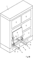
- a piece goods box 1 preferably in the form of a mailbox, in different positions with a series of flaps 2, behind each of which a cargo compartment 3, in particular in the form of a mailer, for receiving and temporary storage of at least one cargo 4, in particular in the form of at least one shipment is arranged.
- the flaps 2 from the in the Fig. 1A illustrated closed position can be adjusted to an open position, which is for one of the flaps 2 in the Fig. 1B is shown.
- the flap 2 closes an access opening 5, which allows access to the associated cargo compartment 3.
- the flap 2 is the access opening 5 and thus the access to the associated cargo compartment 3 free.
- a flap 2 In the in the Fig. 1B illustrated open position of a flap 2 is also a holder 6 of the associated article 3 in a transfer position at least partially disposed outside the cargo compartment 3, which is arranged in the closed position of the flap 2 in a storage position in the article 1.
- the holder 6 is connected via a rail system 7 with the cargo box 1, via which the holder 6 can be adjusted between the storage position and the transfer position and in the reverse direction.
- the adjustment of the holder 6 is effected as a result of the elongate rail system 7 in the form of a displacement of the holder 6.
- Fig. 1C schematically shows the transfer of at least one piece 4 to the at least one holder 6 in the transfer position.
- the transfer takes place in the illustrated preferred method with the aid of a vehicle 8, which is parked next to the cargo box 1 and by means of a transfer device 9, which is formed in the illustrated and so far preferred vehicle 8 in the form of an arm.
- the transferred cargo 4 can be pushed after passing over the holder 6 in the associated cargo compartment 3 and the flap 2 are closed to store the cargo 4 temporarily in the cargo compartment 3 and later return from the cargo compartment 3.
- the vehicle can be driven by a driver or at least partially autonomous. If necessary, it can also be an unmanned vehicle, for example in the sense of a land hazard.
- the holder 6 as in particular in the Fig. 1B is shown, on lateral holding areas 10 bevels 11, which serve the positioning and, if necessary, centering of the shipment 4 on the holder 6 in the transfer of the piece goods 4 to the holder 6.
- lateral holding areas 10 bevels 11 At the chamfers 11 close in the direction of a free space 12 between the holding portions 10 support structures 13 for supporting the at least one piece 4 or to provide a sufficient support surface.
- the holder is U-shaped, with a free space 12 is provided in the center between the lateral legs 14 and the lateral leg 14 connecting crosspiece.
- This free space 12 is in the transfer position of the holder 6 at least partially, in the illustrated and so far preferred cargo box 1 completely, arranged outside the cargo compartment 3 outside.
- the space 12 fulfilled in this position of the holder 6 is an important function for the transfer of the piece goods 4 to the holder 6 and for the acquisition of cargo 4 from the holder. 6
- a pivot joint 16 for pivoting a connecting means 17 of the flap 2 to a relative to the cargo box 1 stationarily arranged pivot axis 18 with the cargo box 1.
- the connection of the flap 2 and the holder 6 is realized in the illustrated and so far preferred cargo box 1 via a pivot fitting 19.
- This pivot fitting 19 forms between the flap 2 and the holder 6, a four-bar chain 20, so that the flap 2 is formed pivotably relative to the holder 6.
- the flap 6 is also displaced as a result of coupled to the holder 6 rail system 7, namely together with the holder. 6
- the rail system 7 may comprise at least one rail 21 of the holder 6 and at least one rail 22 of the piece goods box 1, which are mutually extendable and retractable connected to each other.
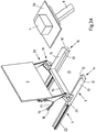
- a rail system 7 the holder 6, the flap 2 and the connection between the holder 6 and the flap 2 of a cargo compartment 3 of the sake of clarity separately shown.
- the holder 6 is shown in the arranged in the cargo box 1 storage position. In this storage position of the holder 6, the flap 2 is arranged in the closed position. Now, if the holder 6 is moved along the rail system 7 forward, the flap 2 pivots upwards and forwards to first release the access opening 5 of the cargo compartment 3 for the holder 6, which can consequently at least partially push through the access opening 5 to the outside, like this in the Fig. 2B is shown.
- the flap 2 pivots further upwards and forwards, wherein the adjusting movement of the flap 2 via the four-bar chain 20 in the connection between the flap 2 and the holder 6 is precisely adapted to the adjustment movement of the holder 6.
- the flap 2 is fixed on the swivel fitting 19 and the pivot joint 16 on the stationary pivot axis 18.
- the rail system 7 is equipped for moving the holder 6 with a stationary fixed to the cargo box 1 rail 22 and on the other hand slidably and fixedly provided with the holder 6 rail 21.
- the holder 6 is fully extended and arranged in the transfer position. Furthermore, the flap 2 is pivoted all the way up and arranged approximately over the rear end of the holder 2 or near the front of the parcel 1. Therefore, the holder 6 is highly accessible to a transfer device 9 for transferring or taking over at least one piece 4.
- each side of the holder 6 may be assigned a drive 23.
- the illustrated and insofar preferred drive 23 is shown as a linear drive in the form of a spindle drive, in which a threaded rod 24 with respect to a drive housing 25 off and retracted again or in the longitudinal direction of the rail system 7 back and forth can be moved. Will the threaded rod 24 in the Fig.
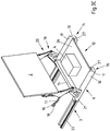
- the method for transferring and / or taking over parcel 4, in particular in the form of consignments, can be determined on the basis of Fig. 3A-C be explained, in which the holder 6 is arranged in each case in the transfer position and the holder 6 forms a free space 12 between holding portions 10, which is arranged at least substantially outside the cargo compartment 3. This is important for the interaction of the holder 6 with a suitable transfer device 9.
- the Indian Fig. 3A illustrated and so far preferred holder 6 is U-shaped and has two lateral holding portions 10 which are formed by the lateral legs 14 of the holder 6, which in turn are connected to each other via a rear cross bar 15.
- the illustrated and so far preferred holder 6 forms the free space 12 in its center.
- the holder 6 as far pushed out of the cargo compartment 3 and / or the cargo box 1 that the space 12 at least partially, in particular completely, in front of the cargo compartment 3 and / or the cargo box 1 is arranged.
- the flap 2, which is positioned in the open position is arranged horizontally in the direction of the transverse web 15 or of the piece goods box 1 at least partially, in particular completely behind the free space 12.
- the free space 12 of the holder 6 for the transfer device 9 for transferring piece goods 4 is accessible.
- the transfer device 9 carries a preferably standardized tray 26 on which Piece 4 is located, which may have 26 very different dimensions as a result of the use of the tray.
- the transfer device 9, which is designed in the manner of an arm shown in the preferred method and thus far, moves from top to bottom through the space defined by the holder 6 12. This can be done at least substantially in the vertical direction. However, this is not mandatory.
- the in the Fig. 3B shown position 4, in which the tray 26 rests on the holder 6, but is still supported by the transfer device 9.
- the tray 26 at least in the event that the tray 26 should be aligned somewhat inaccurate with respect to the holder 6, initially abut against at least one of the bevels 11 and then in the direction of Gravity at least partially slide down on the at least one bevel 11.
- the tray 26 comes in the illustrated and so far preferred example on support structures 13 to lie, which adjoin the chamfers 11 in the direction of the free space 12.
- a wide support surface 27 is provided between the tray 26 and the holder 6.
- a positioning and / or centering of the tray 26 and / or the piece goods 4 is achieved.
- the transfer device 9 is described below, as shown in the Fig. 3C is shown, further down and away from the holder 6 moves, but the tray 26 is further held on the holder 6, in a form-fitting manner in the direction of gravity.
- 26 may optionally be arranged on the tray 26 a cargo 4 or more piece goods.
- very different dimensions of cargo 4 are possible, wherein the cargo 4 is preferably narrower and shorter than the tray 26.
- the holder 6 is moved back into the storage position in the cargo box 1.
- the holder 6 can again be adjusted from the storage position in which the flap 2 closes the access opening 5 of the cargo compartment 3, in the transfer position, in which the flap 2 in the open position is arranged and the access opening 5 of the cargo compartment 3 releases. This is in the Fig. 3C shown.
- a transfer device 9 can be moved from the bottom to the free space 12 of the holder 6, in particular pivoted, wherein the position according to Fig. 3B established.
- the transfer device 9 engages under the tray 26, wherein the tray 26 but still rests on the holder 6. If the transfer device 9 is moved further up, the transfer device 9 raises the tray 26 together with cargo 4 from the holder 6.
- the transfer device 9, the tray 26 together with cargo 4 then, if necessary, carry in a vehicle 8.
- the holder 6 remains in the in Fig. 3A shown transfer position without tray 26 and without cargo 4 back.
- the holder 6 can then be moved back to the storage position and remain there until again cargo 4 is to be transferred to the associated cargo compartment 3, be it with tray 26 or without.
- a container can also be used, in which case the at least one piece 4 is arranged in the container.
- the cargo 4 can not slip so easily from the tray 26. Since nothing else must fundamentally change in the method and the person skilled in the art, instead of the tray 26, can imagine a container with parcel 4 whose base area or the floor can have at least substantially the same dimensions in the plane of the holder 6, a separate representation appears dispensable of the container.
Landscapes
- Engineering & Computer Science (AREA)
- Mechanical Engineering (AREA)
- Transportation (AREA)
- Physics & Mathematics (AREA)
- General Physics & Mathematics (AREA)
- Health & Medical Sciences (AREA)
- Public Health (AREA)
- Warehouses Or Storage Devices (AREA)
- Cartons (AREA)
- Details Of Rigid Or Semi-Rigid Containers (AREA)
- Vehicle Step Arrangements And Article Storage (AREA)
Applications Claiming Priority (1)
| Application Number | Priority Date | Filing Date | Title |
|---|---|---|---|
| DE102017106602.0A DE102017106602A1 (de) | 2017-03-28 | 2017-03-28 | Stückgutkasten und Verfahren zur Übergabe und Lagerung von Stückgut in einem Stückgutkasten |
Publications (2)
| Publication Number | Publication Date |
|---|---|
| EP3381328A1 true EP3381328A1 (fr) | 2018-10-03 |
| EP3381328B1 EP3381328B1 (fr) | 2023-03-08 |
Family
ID=61692192
Family Applications (1)
| Application Number | Title | Priority Date | Filing Date |
|---|---|---|---|
| EP18161726.7A Active EP3381328B1 (fr) | 2017-03-28 | 2018-03-14 | Caisse pour marchandise de détail et procédé de livraison et de stockage des marchandise de détail dans une caisse pour marchandise de détail |
Country Status (4)
| Country | Link |
|---|---|
| US (1) | US11772891B2 (fr) |
| EP (1) | EP3381328B1 (fr) |
| CN (1) | CN108657706B (fr) |
| DE (1) | DE102017106602A1 (fr) |
Families Citing this family (4)
| Publication number | Priority date | Publication date | Assignee | Title |
|---|---|---|---|---|
| CN109157068A (zh) * | 2018-10-25 | 2019-01-08 | 浙江百福玛制冷科技有限公司 | 一种方便放置物品的三明治柜 |
| WO2020227215A1 (fr) * | 2019-05-03 | 2020-11-12 | Eidsmore Paul G | Système ayant un ensemble de levage automatisé et procédé pour charger et décharger une cargaison à partir d'un véhicule de livraison |
| CN112849871A (zh) * | 2020-12-30 | 2021-05-28 | 西湖大学(杭州)智能产业研究院有限公司 | 货架、货物自动装填系统及方法 |
| DE102021006362B4 (de) * | 2021-12-28 | 2024-04-04 | Gebhardt Fördertechnik GmbH | Zentrierstation und Verfahren zum Handhaben zumindest eines Ladungsträgers |
Citations (8)
| Publication number | Priority date | Publication date | Assignee | Title |
|---|---|---|---|---|
| US838194A (en) * | 1906-03-27 | 1906-12-11 | John M Larsh | Mail-box. |
| US1050252A (en) * | 1912-02-23 | 1913-01-14 | Gustave N Thorson | Mail-box. |
| US1220251A (en) * | 1916-06-01 | 1917-03-27 | Claude F Martin | Letter-holder. |
| GB725757A (en) * | 1953-06-09 | 1955-03-09 | Morris Summers | Improvements relating to cabinets and similar articles of furniture |
| WO1992020259A1 (fr) * | 1991-05-17 | 1992-11-26 | Perstorp Ab | Garniture pour element de cuisine ou analogue |
| DE4335742A1 (de) * | 1993-10-20 | 1995-04-27 | Optiplan Gmbh & Co Kg | Schrankauszug für herausnehmbare Einsätze, insbesondere Korbeinsätze für Wäsche etc. |
| US7210616B1 (en) * | 2006-08-23 | 2007-05-01 | Dan Van Watermulen | Extendable curbside mailbox |
| US20170024687A1 (en) * | 2015-07-20 | 2017-01-26 | Deutsche Post Ag | Method and Transfer Apparatus for Transferring Person-related Shipments |
Family Cites Families (28)
| Publication number | Priority date | Publication date | Assignee | Title |
|---|---|---|---|---|
| US338194A (en) * | 1886-03-16 | seeson | ||
| US1728946A (en) * | 1927-08-19 | 1929-09-24 | Fred W Tobey | Card-tray cabinet |
| US1993477A (en) * | 1934-09-14 | 1935-03-05 | Gen Fireproofing Co | Card cabinet |
| US2361525A (en) * | 1944-01-03 | 1944-10-31 | Gen Fireproofing Co | Combination drop door and sliding shelf |
| US2405668A (en) * | 1945-01-04 | 1946-08-13 | Paxton John Warren | Filing cabinet |
| US2814545A (en) * | 1951-12-26 | 1957-11-26 | Irving R Cornish | Filing cabinet |
| US2872267A (en) * | 1958-03-05 | 1959-02-03 | Gen Fireproofing Co | Bookcase |
| US3212835A (en) * | 1962-01-16 | 1965-10-19 | Whirlpool Co | Drop down cabinet door and associated removable receptacle |
| US3200983A (en) * | 1963-04-10 | 1965-08-17 | Akro Mils Inc | Plastic drawer construction |
| US3462208A (en) * | 1966-12-27 | 1969-08-19 | William Horace Black | Drawer form |
| US3582174A (en) * | 1969-10-10 | 1971-06-01 | Recreational Components Inc | Molded drawer |
| US3890024A (en) * | 1972-05-12 | 1975-06-17 | Tomco Plastic Inc | Molded plastic drawer |
| US4174034A (en) * | 1978-04-17 | 1979-11-13 | Hoo William K C | Safety container having a slideable closure |
| US4190004A (en) * | 1978-09-22 | 1980-02-26 | Shure Manufacturing Corporation | Transaction drawer |
| US5211461A (en) * | 1992-04-10 | 1993-05-18 | Artromick International, Inc. | Vertically adjustable extension drawers |
| DE4432820B4 (de) * | 1994-09-15 | 2007-03-22 | MEPLA-WERKE LAUTENSCHLäGER GMBH & CO. KG | Beschlag zur Höhenverstellung von Schubladen |
| US5802991A (en) * | 1996-01-02 | 1998-09-08 | E. F. Bavis & Associates, Inc. | Transaction drawer assembly and method |
| DE29724713U1 (de) * | 1996-10-15 | 2003-03-20 | Protoned B.V., Amsterdam | Mobile Büroeinrichtung |
| US6789860B1 (en) * | 2000-11-06 | 2004-09-14 | Diebold, Incorporated | Deal drawer apparatus |
| DE10312127B4 (de) * | 2003-03-13 | 2006-07-13 | K&S Technologien Gmbh | Kleinteile- und Werkzeugmagazin mit Aus- und Eingabeeinrichtung |
| US7004380B2 (en) * | 2003-04-28 | 2006-02-28 | Gunvaldson Gaylord M | Guided mailbox tray |
| CN201176380Y (zh) | 2008-02-20 | 2009-01-07 | 贸鸿工业股份有限公司 | 升降推车 |
| DE202008008661U1 (de) * | 2008-06-27 | 2008-09-04 | Düperthal Sicherheitstechnik Gmbh & Co. Kg | Schrank, insbesondere Sicherheitsschrank |
| ATE479360T1 (de) * | 2008-06-27 | 2010-09-15 | Dueperthal Sicherheitstechnik | Schrank, insbesondere sicherheitsschrank |
| DE202008011335U1 (de) * | 2008-08-26 | 2008-10-23 | Paul, Dieter, Dipl.-Ing. | Schubboden-Regal |
| PL2636339T3 (pl) * | 2012-03-09 | 2015-04-30 | Peka Metall Ag | Wysuwana część elementu szafki |
| CN205275142U (zh) | 2015-12-23 | 2016-06-01 | 安徽扬帆机械股份有限公司 | 一种叉车用叉夹 |
| TWI594711B (zh) * | 2016-05-31 | 2017-08-11 | 川湖科技股份有限公司 | 滑軌裝置 |
-
2017
- 2017-03-28 DE DE102017106602.0A patent/DE102017106602A1/de not_active Ceased
-
2018
- 2018-03-14 EP EP18161726.7A patent/EP3381328B1/fr active Active
- 2018-03-27 US US15/937,322 patent/US11772891B2/en active Active
- 2018-03-28 CN CN201810263607.7A patent/CN108657706B/zh active Active
Patent Citations (8)
| Publication number | Priority date | Publication date | Assignee | Title |
|---|---|---|---|---|
| US838194A (en) * | 1906-03-27 | 1906-12-11 | John M Larsh | Mail-box. |
| US1050252A (en) * | 1912-02-23 | 1913-01-14 | Gustave N Thorson | Mail-box. |
| US1220251A (en) * | 1916-06-01 | 1917-03-27 | Claude F Martin | Letter-holder. |
| GB725757A (en) * | 1953-06-09 | 1955-03-09 | Morris Summers | Improvements relating to cabinets and similar articles of furniture |
| WO1992020259A1 (fr) * | 1991-05-17 | 1992-11-26 | Perstorp Ab | Garniture pour element de cuisine ou analogue |
| DE4335742A1 (de) * | 1993-10-20 | 1995-04-27 | Optiplan Gmbh & Co Kg | Schrankauszug für herausnehmbare Einsätze, insbesondere Korbeinsätze für Wäsche etc. |
| US7210616B1 (en) * | 2006-08-23 | 2007-05-01 | Dan Van Watermulen | Extendable curbside mailbox |
| US20170024687A1 (en) * | 2015-07-20 | 2017-01-26 | Deutsche Post Ag | Method and Transfer Apparatus for Transferring Person-related Shipments |
Also Published As
| Publication number | Publication date |
|---|---|
| US20180282061A1 (en) | 2018-10-04 |
| US11772891B2 (en) | 2023-10-03 |
| DE102017106602A1 (de) | 2018-10-04 |
| EP3381328B1 (fr) | 2023-03-08 |
| CN108657706A (zh) | 2018-10-16 |
| CN108657706B (zh) | 2022-07-15 |
Similar Documents
| Publication | Publication Date | Title |
|---|---|---|
| EP3254893B1 (fr) | Véhicule de livraison et procédé de livraison d'envois à différents endroits le long d'un itinéraire | |
| EP3511886B1 (fr) | Véhicule de livraison destiné à la livraison d'une boîte d'expédition comportant des expéditions et boîte d'expédition destinée à la réception, au stockage et à la distribution d'expéditions | |
| EP3381328B1 (fr) | Caisse pour marchandise de détail et procédé de livraison et de stockage des marchandise de détail dans une caisse pour marchandise de détail | |
| DE102016106456A1 (de) | Zustellfahrzeug und Verfahren zum Abliefern von Sendungen an unterschiedlichen Orten entlang einer Zustellroute | |
| EP2144830B1 (fr) | Procédé et dispositif pour emballer des grands emballages pour bouteilles | |
| EP2256038B1 (fr) | Installation de chargement de bagages dans un conteneur | |
| EP3461753B1 (fr) | Procédé d'ouverture automatique d'un moyen de support ainsi que dispositif de mise en oeuvre dudit procédé | |
| EP2322290A2 (fr) | Dispositif et procédé de tri d'objets | |
| DE102021207911A1 (de) | Vorrichtung und Verfahren zum automatischen Entladen einer hängend geförderten Transporttasche sowie Hängeförderanlage mit einer derartigen Vorrichtung | |
| CH686952A5 (de) | Verfahren und Vorrichtung zum mechanisierten Auf- und Abladen. | |
| DE2817094A1 (de) | Vorrichtung zum zusammenpressen und verpacken von gegenstaenden | |
| DE102022104177A1 (de) | Verpackungsanlage und Verfahren zur Zuführung von flächigen Verpackungsmitteln zu einer Verpackungsanlage | |
| WO2015173040A1 (fr) | Poste de transfert permettant le transfert de marchandises au détail entre un véhicule et un support | |
| DE10012090A1 (de) | Verfahren und Einrichtung zum Beladen von in Flugzeugen mitführbaren Containern | |
| DE102017005261A1 (de) | Behälter zur vereinzelten Abgabe von Schüttgut und Verfahren zum Betrieb mit einem Transport-Roboter oder einem Längsförderer | |
| EP0256403B1 (fr) | Procédé de transfert automatique de muselets en fil métallique pour bouteilles à champagne d'une station d'usinage à un empilage ou d'un empilage à une station d'usinage ultérieure et dispositif pour la mise en oeuvre de ce procédé | |
| EP2596708B1 (fr) | Agencement de manipulation de récipients de transport pour des articles en forme de tige de l'industrie de traitement du tabac et procédé destiné à modifier le niveau de remplissage de récipients de transport | |
| DE1088877B (de) | Behaelter zur Aufnahme eines Stapels flacher Gegenstaende | |
| DE202010012374U1 (de) | Stückgutfördereinrichtung | |
| EP0924144B1 (fr) | Magasin à rayonnage | |
| DE102018100734B4 (de) | Transportwagen-Beladestation | |
| CH708471A2 (de) | Container-Station für ISO-Container und Wechselbehälter. | |
| DE3816448C2 (fr) | ||
| DE202015102809U1 (de) | Fahrzeug, insbesondere Lastentransportrad | |
| DE1781469C2 (de) | Verschiebewagen eines automatischen Speichersystems mit einem Ladeschlitten und diesem zugeordneter Ausrichtvorrichtung |
Legal Events
| Date | Code | Title | Description |
|---|---|---|---|
| PUAI | Public reference made under article 153(3) epc to a published international application that has entered the european phase |
Free format text: ORIGINAL CODE: 0009012 |
|
| STAA | Information on the status of an ep patent application or granted ep patent |
Free format text: STATUS: THE APPLICATION HAS BEEN PUBLISHED |
|
| AK | Designated contracting states |
Kind code of ref document: A1 Designated state(s): AL AT BE BG CH CY CZ DE DK EE ES FI FR GB GR HR HU IE IS IT LI LT LU LV MC MK MT NL NO PL PT RO RS SE SI SK SM TR |
|
| AX | Request for extension of the european patent |
Extension state: BA ME |
|
| STAA | Information on the status of an ep patent application or granted ep patent |
Free format text: STATUS: REQUEST FOR EXAMINATION WAS MADE |
|
| 17P | Request for examination filed |
Effective date: 20190327 |
|
| RBV | Designated contracting states (corrected) |
Designated state(s): AL AT BE BG CH CY CZ DE DK EE ES FI FR GB GR HR HU IE IS IT LI LT LU LV MC MK MT NL NO PL PT RO RS SE SI SK SM TR |
|
| STAA | Information on the status of an ep patent application or granted ep patent |
Free format text: STATUS: EXAMINATION IS IN PROGRESS |
|
| 17Q | First examination report despatched |
Effective date: 20201102 |
|
| RAP1 | Party data changed (applicant data changed or rights of an application transferred) |
Owner name: STREETSCOOTER GMBH |
|
| GRAP | Despatch of communication of intention to grant a patent |
Free format text: ORIGINAL CODE: EPIDOSNIGR1 |
|
| STAA | Information on the status of an ep patent application or granted ep patent |
Free format text: STATUS: GRANT OF PATENT IS INTENDED |
|
| INTG | Intention to grant announced |
Effective date: 20220916 |
|
| GRAS | Grant fee paid |
Free format text: ORIGINAL CODE: EPIDOSNIGR3 |
|
| GRAA | (expected) grant |
Free format text: ORIGINAL CODE: 0009210 |
|
| STAA | Information on the status of an ep patent application or granted ep patent |
Free format text: STATUS: THE PATENT HAS BEEN GRANTED |
|
| AK | Designated contracting states |
Kind code of ref document: B1 Designated state(s): AL AT BE BG CH CY CZ DE DK EE ES FI FR GB GR HR HU IE IS IT LI LT LU LV MC MK MT NL NO PL PT RO RS SE SI SK SM TR |
|
| REG | Reference to a national code |
Ref country code: CH Ref legal event code: EP Ref country code: AT Ref legal event code: REF Ref document number: 1551996 Country of ref document: AT Kind code of ref document: T Effective date: 20230315 |
|
| REG | Reference to a national code |
Ref country code: IE Ref legal event code: FG4D Free format text: LANGUAGE OF EP DOCUMENT: GERMAN |
|
| REG | Reference to a national code |
Ref country code: DE Ref legal event code: R096 Ref document number: 502018011718 Country of ref document: DE |
|
| P01 | Opt-out of the competence of the unified patent court (upc) registered |
Effective date: 20230517 |
|
| REG | Reference to a national code |
Ref country code: LT Ref legal event code: MG9D |
|
| REG | Reference to a national code |
Ref country code: NL Ref legal event code: MP Effective date: 20230308 |
|
| PG25 | Lapsed in a contracting state [announced via postgrant information from national office to epo] |
Ref country code: RS Free format text: LAPSE BECAUSE OF FAILURE TO SUBMIT A TRANSLATION OF THE DESCRIPTION OR TO PAY THE FEE WITHIN THE PRESCRIBED TIME-LIMIT Effective date: 20230308 Ref country code: NO Free format text: LAPSE BECAUSE OF FAILURE TO SUBMIT A TRANSLATION OF THE DESCRIPTION OR TO PAY THE FEE WITHIN THE PRESCRIBED TIME-LIMIT Effective date: 20230608 Ref country code: LV Free format text: LAPSE BECAUSE OF FAILURE TO SUBMIT A TRANSLATION OF THE DESCRIPTION OR TO PAY THE FEE WITHIN THE PRESCRIBED TIME-LIMIT Effective date: 20230308 Ref country code: LT Free format text: LAPSE BECAUSE OF FAILURE TO SUBMIT A TRANSLATION OF THE DESCRIPTION OR TO PAY THE FEE WITHIN THE PRESCRIBED TIME-LIMIT Effective date: 20230308 Ref country code: HR Free format text: LAPSE BECAUSE OF FAILURE TO SUBMIT A TRANSLATION OF THE DESCRIPTION OR TO PAY THE FEE WITHIN THE PRESCRIBED TIME-LIMIT Effective date: 20230308 Ref country code: ES Free format text: LAPSE BECAUSE OF FAILURE TO SUBMIT A TRANSLATION OF THE DESCRIPTION OR TO PAY THE FEE WITHIN THE PRESCRIBED TIME-LIMIT Effective date: 20230308 |
|
| PG25 | Lapsed in a contracting state [announced via postgrant information from national office to epo] |
Ref country code: SE Free format text: LAPSE BECAUSE OF FAILURE TO SUBMIT A TRANSLATION OF THE DESCRIPTION OR TO PAY THE FEE WITHIN THE PRESCRIBED TIME-LIMIT Effective date: 20230308 Ref country code: NL Free format text: LAPSE BECAUSE OF FAILURE TO SUBMIT A TRANSLATION OF THE DESCRIPTION OR TO PAY THE FEE WITHIN THE PRESCRIBED TIME-LIMIT Effective date: 20230308 Ref country code: GR Free format text: LAPSE BECAUSE OF FAILURE TO SUBMIT A TRANSLATION OF THE DESCRIPTION OR TO PAY THE FEE WITHIN THE PRESCRIBED TIME-LIMIT Effective date: 20230609 Ref country code: FI Free format text: LAPSE BECAUSE OF FAILURE TO SUBMIT A TRANSLATION OF THE DESCRIPTION OR TO PAY THE FEE WITHIN THE PRESCRIBED TIME-LIMIT Effective date: 20230308 |
|
| PG25 | Lapsed in a contracting state [announced via postgrant information from national office to epo] |
Ref country code: SM Free format text: LAPSE BECAUSE OF FAILURE TO SUBMIT A TRANSLATION OF THE DESCRIPTION OR TO PAY THE FEE WITHIN THE PRESCRIBED TIME-LIMIT Effective date: 20230308 Ref country code: RO Free format text: LAPSE BECAUSE OF FAILURE TO SUBMIT A TRANSLATION OF THE DESCRIPTION OR TO PAY THE FEE WITHIN THE PRESCRIBED TIME-LIMIT Effective date: 20230308 Ref country code: PT Free format text: LAPSE BECAUSE OF FAILURE TO SUBMIT A TRANSLATION OF THE DESCRIPTION OR TO PAY THE FEE WITHIN THE PRESCRIBED TIME-LIMIT Effective date: 20230710 Ref country code: EE Free format text: LAPSE BECAUSE OF FAILURE TO SUBMIT A TRANSLATION OF THE DESCRIPTION OR TO PAY THE FEE WITHIN THE PRESCRIBED TIME-LIMIT Effective date: 20230308 Ref country code: CZ Free format text: LAPSE BECAUSE OF FAILURE TO SUBMIT A TRANSLATION OF THE DESCRIPTION OR TO PAY THE FEE WITHIN THE PRESCRIBED TIME-LIMIT Effective date: 20230308 |
|
| REG | Reference to a national code |
Ref country code: CH Ref legal event code: PL |
|
| PG25 | Lapsed in a contracting state [announced via postgrant information from national office to epo] |
Ref country code: SK Free format text: LAPSE BECAUSE OF FAILURE TO SUBMIT A TRANSLATION OF THE DESCRIPTION OR TO PAY THE FEE WITHIN THE PRESCRIBED TIME-LIMIT Effective date: 20230308 Ref country code: PL Free format text: LAPSE BECAUSE OF FAILURE TO SUBMIT A TRANSLATION OF THE DESCRIPTION OR TO PAY THE FEE WITHIN THE PRESCRIBED TIME-LIMIT Effective date: 20230308 Ref country code: IS Free format text: LAPSE BECAUSE OF FAILURE TO SUBMIT A TRANSLATION OF THE DESCRIPTION OR TO PAY THE FEE WITHIN THE PRESCRIBED TIME-LIMIT Effective date: 20230708 Ref country code: AL Free format text: LAPSE BECAUSE OF FAILURE TO SUBMIT A TRANSLATION OF THE DESCRIPTION OR TO PAY THE FEE WITHIN THE PRESCRIBED TIME-LIMIT Effective date: 20230308 |
|
| REG | Reference to a national code |
Ref country code: BE Ref legal event code: MM Effective date: 20230331 |
|
| REG | Reference to a national code |
Ref country code: DE Ref legal event code: R097 Ref document number: 502018011718 Country of ref document: DE |
|
| PG25 | Lapsed in a contracting state [announced via postgrant information from national office to epo] |
Ref country code: LU Free format text: LAPSE BECAUSE OF NON-PAYMENT OF DUE FEES Effective date: 20230314 |
|
| PLBE | No opposition filed within time limit |
Free format text: ORIGINAL CODE: 0009261 |
|
| STAA | Information on the status of an ep patent application or granted ep patent |
Free format text: STATUS: NO OPPOSITION FILED WITHIN TIME LIMIT |
|
| PG25 | Lapsed in a contracting state [announced via postgrant information from national office to epo] |
Ref country code: MC Free format text: LAPSE BECAUSE OF FAILURE TO SUBMIT A TRANSLATION OF THE DESCRIPTION OR TO PAY THE FEE WITHIN THE PRESCRIBED TIME-LIMIT Effective date: 20230308 |
|
| REG | Reference to a national code |
Ref country code: IE Ref legal event code: MM4A |
|
| PG25 | Lapsed in a contracting state [announced via postgrant information from national office to epo] |
Ref country code: SI Free format text: LAPSE BECAUSE OF FAILURE TO SUBMIT A TRANSLATION OF THE DESCRIPTION OR TO PAY THE FEE WITHIN THE PRESCRIBED TIME-LIMIT Effective date: 20230308 Ref country code: MC Free format text: LAPSE BECAUSE OF FAILURE TO SUBMIT A TRANSLATION OF THE DESCRIPTION OR TO PAY THE FEE WITHIN THE PRESCRIBED TIME-LIMIT Effective date: 20230308 Ref country code: LI Free format text: LAPSE BECAUSE OF NON-PAYMENT OF DUE FEES Effective date: 20230331 Ref country code: IE Free format text: LAPSE BECAUSE OF NON-PAYMENT OF DUE FEES Effective date: 20230314 Ref country code: DK Free format text: LAPSE BECAUSE OF FAILURE TO SUBMIT A TRANSLATION OF THE DESCRIPTION OR TO PAY THE FEE WITHIN THE PRESCRIBED TIME-LIMIT Effective date: 20230308 Ref country code: CH Free format text: LAPSE BECAUSE OF NON-PAYMENT OF DUE FEES Effective date: 20230331 |
|
| 26N | No opposition filed |
Effective date: 20231211 |
|
| PG25 | Lapsed in a contracting state [announced via postgrant information from national office to epo] |
Ref country code: BE Free format text: LAPSE BECAUSE OF NON-PAYMENT OF DUE FEES Effective date: 20230331 |
|
| REG | Reference to a national code |
Ref country code: AT Ref legal event code: MM01 Ref document number: 1551996 Country of ref document: AT Kind code of ref document: T Effective date: 20230314 |
|
| PG25 | Lapsed in a contracting state [announced via postgrant information from national office to epo] |
Ref country code: IT Free format text: LAPSE BECAUSE OF FAILURE TO SUBMIT A TRANSLATION OF THE DESCRIPTION OR TO PAY THE FEE WITHIN THE PRESCRIBED TIME-LIMIT Effective date: 20230308 |
|
| PG25 | Lapsed in a contracting state [announced via postgrant information from national office to epo] |
Ref country code: AT Free format text: LAPSE BECAUSE OF NON-PAYMENT OF DUE FEES Effective date: 20230314 |
|
| PG25 | Lapsed in a contracting state [announced via postgrant information from national office to epo] |
Ref country code: AT Free format text: LAPSE BECAUSE OF NON-PAYMENT OF DUE FEES Effective date: 20230314 |
|
| PG25 | Lapsed in a contracting state [announced via postgrant information from national office to epo] |
Ref country code: BG Free format text: LAPSE BECAUSE OF FAILURE TO SUBMIT A TRANSLATION OF THE DESCRIPTION OR TO PAY THE FEE WITHIN THE PRESCRIBED TIME-LIMIT Effective date: 20230308 |
|
| PG25 | Lapsed in a contracting state [announced via postgrant information from national office to epo] |
Ref country code: BG Free format text: LAPSE BECAUSE OF FAILURE TO SUBMIT A TRANSLATION OF THE DESCRIPTION OR TO PAY THE FEE WITHIN THE PRESCRIBED TIME-LIMIT Effective date: 20230308 |
|
| PG25 | Lapsed in a contracting state [announced via postgrant information from national office to epo] |
Ref country code: CY Free format text: LAPSE BECAUSE OF FAILURE TO SUBMIT A TRANSLATION OF THE DESCRIPTION OR TO PAY THE FEE WITHIN THE PRESCRIBED TIME-LIMIT; INVALID AB INITIO Effective date: 20180314 |
|
| PG25 | Lapsed in a contracting state [announced via postgrant information from national office to epo] |
Ref country code: HU Free format text: LAPSE BECAUSE OF FAILURE TO SUBMIT A TRANSLATION OF THE DESCRIPTION OR TO PAY THE FEE WITHIN THE PRESCRIBED TIME-LIMIT; INVALID AB INITIO Effective date: 20180314 |
|
| PG25 | Lapsed in a contracting state [announced via postgrant information from national office to epo] |
Ref country code: TR Free format text: LAPSE BECAUSE OF FAILURE TO SUBMIT A TRANSLATION OF THE DESCRIPTION OR TO PAY THE FEE WITHIN THE PRESCRIBED TIME-LIMIT Effective date: 20230308 |
|
| PGFP | Annual fee paid to national office [announced via postgrant information from national office to epo] |
Ref country code: GB Payment date: 20260326 Year of fee payment: 9 |
|
| PGFP | Annual fee paid to national office [announced via postgrant information from national office to epo] |
Ref country code: DE Payment date: 20260327 Year of fee payment: 9 |
|
| PGFP | Annual fee paid to national office [announced via postgrant information from national office to epo] |
Ref country code: FR Payment date: 20260326 Year of fee payment: 9 |