EP3382101A2 - Dispositif de nettoyage et procédé de nettoyage correspondant - Google Patents
Dispositif de nettoyage et procédé de nettoyage correspondant Download PDFInfo
- Publication number
- EP3382101A2 EP3382101A2 EP18152570.0A EP18152570A EP3382101A2 EP 3382101 A2 EP3382101 A2 EP 3382101A2 EP 18152570 A EP18152570 A EP 18152570A EP 3382101 A2 EP3382101 A2 EP 3382101A2
- Authority
- EP
- European Patent Office
- Prior art keywords
- suction
- cleaning device
- nozzle tubes
- spray jets
- impact area
- Prior art date
- Legal status (The legal status is an assumption and is not a legal conclusion. Google has not performed a legal analysis and makes no representation as to the accuracy of the status listed.)
- Granted
Links
Images



Classifications
-
- E—FIXED CONSTRUCTIONS
- E01—CONSTRUCTION OF ROADS, RAILWAYS, OR BRIDGES
- E01H—STREET CLEANING; CLEANING OF PERMANENT WAYS; CLEANING BEACHES; DISPERSING OR PREVENTING FOG IN GENERAL CLEANING STREET OR RAILWAY FURNITURE OR TUNNEL WALLS
- E01H1/00—Removing undesirable matter from roads or like surfaces, with or without moistening of the surface
- E01H1/10—Hydraulically loosening or dislodging undesirable matter; Raking or scraping apparatus ; Removing liquids or semi-liquids e.g., absorbing water, sliding-off mud
- E01H1/101—Hydraulic loosening or dislodging, combined or not with mechanical loosening or dislodging, e.g. road washing machines with brushes or wipers
- E01H1/103—Hydraulic loosening or dislodging, combined or not with mechanical loosening or dislodging, e.g. road washing machines with brushes or wipers in which the soiled loosening or washing liquid is removed, e.g. by suction
-
- E—FIXED CONSTRUCTIONS
- E01—CONSTRUCTION OF ROADS, RAILWAYS, OR BRIDGES
- E01H—STREET CLEANING; CLEANING OF PERMANENT WAYS; CLEANING BEACHES; DISPERSING OR PREVENTING FOG IN GENERAL CLEANING STREET OR RAILWAY FURNITURE OR TUNNEL WALLS
- E01H1/00—Removing undesirable matter from roads or like surfaces, with or without moistening of the surface
- E01H1/10—Hydraulically loosening or dislodging undesirable matter; Raking or scraping apparatus ; Removing liquids or semi-liquids e.g., absorbing water, sliding-off mud
- E01H1/105—Raking, scraping or other mechanical loosening devices, e.g. for caked dirt ; Apparatus for mechanically moving dirt on road surfaces, e.g. wipers for evacuating mud
Definitions
- the invention relates to a cleaning device for a substrate and a cleaning method for a substrate, in particular flat substrates with non-closed surface can be cleaned, such as artificial turf.
- a method is known with which a substrate such as artificial turf can be cleaned.
- a nozzle tube is provided with a plurality of individual nozzles, which form a liquid curtain by adjacent sprays. This meets at an adjustable angle to the ground in a strip-like or line-like impact area. The angle can be in a range of 15 ° to 30 °. Dirt particles entrained by the spray jets are thrown or rinsed on a pick-up lamp arranged just behind the impact area, ie moved, and can easily be transported away from there.
- the disadvantage here is that the removal of dirt particles after the recording lamp may be difficult under certain circumstances.
- the invention has for its object to provide an aforementioned cleaning device and a corresponding cleaning method for substrates with which problems of the prior art can be solved and it is possible in particular, from or from the ground dissolved or entrained dirt particles as simple and as complete as possible to be able to remove.
- a cleaning device having the features of claim 1 and by a method for cleaning a substrate with such a cleaning device with the features of claim 14.
- Advantageous and preferred embodiments of the invention are the subject of further claims and are explained in more detail below. In this case, some of the features are described only for the cleaning device or only the method for cleaning. However, they should be able to apply independently and independently of each other both for a cleaning device as well as for a method for cleaning independently.
- the wording of the claims is incorporated herein by express reference.
- the cleaning device with the particularly advantageous flat surfaces can be cleaned with non-closed surface, such as artificial turf, has two nozzle tubes, each having a plurality of individual nozzles for generating juxtaposed spray jets per nozzle tube. These individual nozzles may under certain circumstances form a liquid curtain.
- the spray jets of the two nozzle tubes meet from different or opposite directions in a common impact area on the ground, the directions can be opposite viewed from above. Such an impact area is advantageously strip-shaped or linear.
- the spray can hit each other directly. Alternatively, they can hit the ground with a distance of no more than 5 cm or no more than 3 cm from each other.
- a suction device is arranged in order to be able to remove or suck off liquid spouting upwards and, above all, to be able to remove or suck off dirt particles or impurities which have been removed from the underground or from the substrate by the spray jets and entrained. These dirt particles or impurities can also splash up, so to speak, advantageously to a height of 3 cm or more above the ground. There they can then be detected well by the suction device arranged above or be sucked off.
- the suction device has an elongated suction slot, which is advantageously approximately as long as the impact area.
- the suction slot can be adjusted in height relative to the impact area. Additionally or alternatively, the suction slot can be adjusted in its width.
- the first measure of the height adjustment can influence how many dirt particles or impurities or upwardly splashing liquid are sucked off.
- the second measure of the adjustment of the width of the suction slot can essentially be used to set the speed of the air at the suction, which ultimately also influences the suction power for liquid and dirt particles or impurities.
- the height and / or width of the suction slot can also be adjusted or adjusted during a cleaning process, for example, to changing factors such as the nature of the substrate or the amount of dirt particles.
- height and width of the suction slot can be adjusted simultaneously and / or synchronously. This makes an adjustment easier with respect to finding an optimum value, possibly also with respect to the mechanical complexity of such adjustability.
- Such an adjustability can be realized such that the suction slot automatically becomes wider when moving upwards, and at a Movement down automatically becomes narrower. As the suction slot moves downwards, it comes closer to the impact area, so that dirt particles released from the spray jets or entrained upward can spray less far to the side, so that they can also be caught by a relatively narrow suction slot. It should be added that in a narrow suction slot, the flow velocity near the suction slot is considerably higher, so that in turn means that the dirt particles sucked more towards the narrow suction slot and then sucked through this and thus can be removed.
- the suction slot extends over the impact area or just above it, ie vertically above it. This is especially true for a line-like or linear impact area, which can be particularly advantageous exactly in the middle between the two nozzle tubes.
- the suction slot may be substantially formed by the lower edges of two opposing Absaugwangen, which may be, so to speak elongated and parallel to the nozzle tubes extending surface components.
- the suction cheeks can thereby be moved or moved linearly in such a way, in particular with a vertical component, that both suction cheeks can be moved toward a common line which runs parallel to their lower edge and parallel to the ground.
- this common line the suction cheeks can be moved to or from her. It is possible that the suction cheeks are simultaneously and similarly displaced, so that, for example, only a single actuator is necessary and in particular problems with synchronization can be avoided.
- this common line can also be below the impact of the spray jets, but it is advantageous above it. This makes it possible to make the suction slot actually very narrow, for example, with a width of less than 1 cm or even only 5 mm, the suction slot is still above the impact area and thus actually bring dirt or impurities up can be from the underground.
- the lower ends of the suction cheeks are specially designed. It is thus possible for the outer edges facing away from the suction slot to be rounded.
- Such a rounding can be wide or generous, possibly with a radius of 50% to 100% of the thickness of the suction cheek at this lower end. Through this wide rounding, so to speak, from the side approaching air very well and preferably without turbulence, so as quickly as possible, to flow around the lower end of the suction and thus also with great speed and therefore good suction the air above the impingement up swept up and so well sucked up dirt particles entrained.
- An inner edge of the lower ends of the suction cheeks directly forming the suction slot can not have any rounding or only a slight rounding. This form is less crucial for the suction effect.
- the aforementioned Absaugwangen are arranged on opposite sides of a downwardly open suction box. These outer sides can diverge from bottom to top and thus be inclined so that this inclination causes the path of movement of the suction cheeks towards each other during a downward movement or away from each other in an upward movement.
- the inclination may in particular be mirror-symmetrical to a vertical. This is particularly advantageous, although the arrangement of the nozzle tubes with respect to distance to this vertical and height above the ground is the same.
- linear guides or the like be provided on the outer sides of the suction box, where they are movable upwards or downwards.
- these may be elongated slots in the suction cheeks, into which guide pins or guide projections extend, which protrude from the outer sides of the suction box.
- the elongated slots are formed exactly along the desired direction of movement or define them. It is possible to interchange the arrangement of longitudinal slots in the Absaugwangen and guide projections on the outer sides of the suction box also.
- the outer sides of the suction box do not necessarily have to simultaneously form the inner sides of a suction channel or suction chamber of the suction box. Rather, they advantageously form a structural unit or a structural unit with these inner sides, so that separate components can also be provided for the formation of the inner sides.
- the suction box can have a plurality of suction connections at the top or at an upper side. These can be guided by means of one or more pipes to a suction device, as it is known per se for such cleaning devices. In such a suction device and dirt particles and liquid can be separated, so that in particular the liquid can be used later or directly again for the cleaning process. The dirt particles are advantageously collected in a separate store.
- the Suction connections preferably go upwards from the suction box, wherein they can then also be angled relatively short behind it and if necessary can also be brought together, so that overall only one or two suction pipes lead to the suction device itself.
- suction box subdivisions are provided such that they lead from an inner side wall of the suction box to another opposite inner side wall or extend.
- These subdivisions extend not only from an inner side to the opposite, but also from top to bottom and in particular up to an upper side of the interior of the suction box.
- This interior may be formed such that the subdivisions from the bottom up are strictly monotonously narrow or reduce their width.
- the inner sides of the suction box may even be inclined in opposite directions to the respective aforementioned outer sides with the suction cheeks thereon.
- This has the advantage that the flow velocity increases as a result of a reduction in the overall cross-section to a suction connection on the upper side, and thus liquid and dirt particles can be reliably sucked off and thus transported away.
- the speed of the dirt particles is high due to the leaching by the hitting the ground spray, it decreases naturally on the way up or mandatory, in particular even after the cross section above the narrow suction slot can widen slightly again.
- a renewed acceleration upwards is beneficial.
- a suction connection is provided at the top of the suction box.
- this may be three to six or even eight suction ports on the top, wherein suction regions below these suction ports, which are adjacent to each other, may be separated from each other by the partitions.
- the nozzle tubes are adjustable in height above the ground and / or in their distance from one another.
- This can be achieved by basically any guides or brackets for the nozzle tubes.
- This is achieved by guide slots for the nozzle tubes in side walls or side plates, which are arranged at the beginning and at the end of the suction slot or the suction box.
- the nozzle tubes have an adjustable angle of the spray jets to be cleaned underground.
- the nozzle tubes can be rotated, for example, about a central longitudinal axis, so that at the same time changes the angle for all its spray jets at each nozzle tube.
- the nozzle tubes may be moved in a guide or guide slot such that the orientation and thus the angle of the spray jets change to the ground. If the angle is larger, the spray jets can penetrate deeper into the ground and thus also transport deeper impurities or dirt particles upwards or tear them up so that they can be sucked off.
- the danger may increase that, for example, in the case of a synthetic turf filled with sand or granules, too much of the backfilling is carried along as suction and suction and thus removed from the underground, which would obviously be detrimental.
- This effect can, of course, be counteracted by a flatter angle of incidence and by the pressure of the spray jets being somewhat reduced.
- a guide device for the nozzle tubes may be formed such that the nozzle tubes are adjusted identically and in opposite directions.
- they are adjusted such that they are always arranged mirror-symmetrically to a vertical center plane, which extends through the impact area.
- the nozzle tubes with their nozzles therein, in particular flat-jet nozzles can always also be arranged and aligned mirror-symmetrically to this center plane.
- the guide device for the nozzle tubes have a vertically movable guide carriage, advantageously on both sides of the nozzle tubes.
- the guide device may comprise a holding rod which extends from the guide carriage to each nozzle tube and advantageously has a connection with the nozzle tube, which lies in the extension thereof.
- the guide device may comprise an adjusting rod, which also from the guide carriage to each nozzle tube runs, but advantageously by means of an articulated lever or the like. is connected to the nozzle tube, said compound is not in the extension of the nozzle tube.
- Holding rod and adjusting rod can run parallel to each other, so form a kind of parallel guide for the nozzle tubes and their movement.
- An articulation lever should be rotatably connected to the nozzle tube and ensure that this moves in a movement due to the support rod or twisted so that the angle of incidence behaves as desired, advantageously does not change.
- the guide device and thus also holding rod and adjusting rod are advantageously designed such that upon adjustment of the guide carriage and thus changing the position of the nozzle tubes an angle of incidence of their spray jets on the ground always remains the same and does not change.
- a cleaning and thus also a cleaning result can be optimized by changing the position of the nozzle tubes.
- the two nozzle tubes move simultaneously and identically, ie always run symmetrically to a vertical center plane.
- the spray jets are influenced by the height and width of the suction slot and possibly by a pressure on the nozzle tubes.
- the guide carriage can be adjusted and the nozzle tubes can change their position, but advantageously such that the angle of incidence remains the same.
- an angle of incidence of the spray jets in both nozzle tubes also differ, under certain circumstances it can also be adjustable.
- an adaptation to different substrates or their degree of contamination can be achieved.
- the nozzle tubes have flat jet nozzles, more preferably 5 to 15 flat jet nozzles.
- the spray jets are flat jets, which lie essentially in one plane. A flat jet can therefore be fan-shaped or fanned out, so to speak.
- the flat jets form a liquid curtain per nozzle tube, which radiates into the impact area. Due to the particularly advantageous symmetrical irradiation of the spray jets on or in the ground, the dirt particles are not only in the direction of the corresponding nozzle tube away slightly upwards or slightly slanted upwards, but so to speak, mainly upwards or even vertically upwards. They reach in a relatively narrow area above the impact area a sufficient height above the ground, for example, at least 3 cm, from which they can then be very effectively sucked by means of the above-described suction slot.
- the individual flat jet nozzles can be designed to be adjustable, for example with regard to the cross section or width of the respective spray jet. So a profile can be set.
- the respective spray jets formed by them from the two different directions can be symmetrical to a vertical plane along the impact area, preferably at the same angle to the ground.
- a treatment device for treating the surface with liquid can be provided by applying this liquid.
- a care liquid can be applied, advantageously a disinfecting liquid in order to disinfect the surface or an artificial turf during or after cleaning.
- the treatment device has a tank and at least one discharge device with at least one discharge opening for the liquid and a line from the tank to the discharge device.
- the discharge device may advantageously be a tube, for example a kind of spray bar, with a plurality of discharge openings thereon, particularly advantageously in the form of nozzle openings.
- the discharge can be carried out with high pressure or with a slight overpressure, depending on the desired penetration depth.
- a pump or a similar device for generating pressure can be provided, for example on the tank or on the said line.
- the discharge device may preferably be arranged in the direction of travel of the cleaning device behind the suction device, in particular behind the rear nozzle tube. This prevents the liquid from being washed out again. It can be arranged on a chassis or frame, which also carries the nozzle tubes.
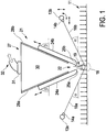
- FIG. 1 is a schematic side view of a suction device 21 of a cleaning device according to the invention shown, with reference to the basic principle of the cleaning method according to the invention is explained.
- a cleaning device then shown overall in the other figures has two nozzle tubes 13a and 13b which are arranged at a distance from one another and have approximately the same height above a surface to be cleaned, in this case an artificial turf 11. This can be a few centimeters, for example 5 cm to 20 cm or even 30 cm.
- the nozzle tubes 13a and 13b respectively have flat-jet nozzles 14a and 14b which generate flat jets or fan-out flat spray jets 16a and 16b which can form a kind of flat liquid curtain. They are facing each other and directed diagonally downwards.
- the nozzle tubes 13a and 13b may each have five to thirty such flat jet nozzles 14a and 14b.
- the nozzle tubes 13a and 13b are the same design and arranged symmetrically to each other.
- the angle ⁇ of the sprays 16a and 16b to the horizontal or to the Kunststoffrasten 11 should be the same for both sides and may for example be 20 °, but generally in a range between 15 ° and 25 ° or even reach 30 °.
- the angle ⁇ may under certain circumstances also be adjusted or be adjustable, as will be explained in more detail below.
- the angle ⁇ for the two spray jets 16a and 16b may be different, it is advantageous for them to be the same.
- the spray jets 16 a and 16 b meet in an impact area 18, which is shown in dashed lines and which extends approximately along a line parallel to the nozzle tubes 13 and the artificial turf 11.
- the impact area 18 can, depending on the height of the nozzle tubes 13 and angle ⁇ of the spray jets 16, in the upper region of the artificial turf 11 or in the lower region, ie where a usual for artificial turf 11 filling in its lower region, formed of sand and / or granules or the like., Is.
- the penetration depth of the spray jets 16 can be adjusted in the artificial turf 11 and thus also a cleaning effect.
- About the impact area 18 is indicated by upward strokes, as liquid and dirt particles 19 are thrown upwards. This is the effect of the spray jets 16 spraying into the impact area 18, usually with great pressure.
- the upwardly thrown dirt particles 19, together with the water or the liquid, can also form a kind of cloud which, although not only, but mainly, is thrown upwards.
- a suction device 21 is provided above the impact area 18, for which in particular the lower suction slot 22 is relevant or important for the function according to the invention.
- the suction slot 22 is arranged above and above the impact area 18 and thus the dirt particles 19.
- it is directly vertically arranged above it, so in a vertical line above it.
- the height of the suction slot 22 above the impact area 18 or above the artificial turf 11 is adjustable and should advantageously be in a range of 2 cm to 10 cm or a maximum of 15 cm.
- the spray jets 16 can still spray unhindered into the impact area 18 and at the same time sufficient air can flow into the clearance area to entrain the upwardly thrown dirt particles 19 and the sprayed water upwards and thus to be able to aspirate.
- the width of the suction slot 22 is adjustable.
- the flow velocity in the vicinity and also directly at the suction slot 22 can be adjusted, which exerts on the suction effect.
- oblique suction cheeks 24a and 24b are provided which are inclined at the same angle ⁇ to the ground or to the artificial turf 11. This angle is about 70 ° here, but can generally in a range of 60 ° to 80 °.
- the suction cheeks 24 are arranged on outer sides 28a and 28b of a suction box 27 in a manner which will be explained in more detail later. Are advantageous they move simultaneously and in the same direction, as indicated by the arrows. If they are moved down, the suction slot 22 is moved so to speak downward, so closer to the impact area 18, but at the same time narrower due to the inclination.
- this adjustment of the width of the suction slot 22 and its height above the impact area 18 could also be formed separately adjustable. But then also increase the mechanical and design effort and the control effort. Optimum height and width of the suction slot 22 may also need to be adjusted in the particular application, since this depends on the type of artificial turf 11 and the degree of its contamination and the desired degree of cleaning.
- suction cheeks 24 are strongly rounded at the outer lower edges 25a and 25b, so that they have the outer shape of a quarter circle. As a result, sucked in air from the left and right outside next to the Absaugwangen 24 flow better and faster to flow around the outer lower edges 25a and 25b, which improves the suction.
- the inner lower edges are here relatively sharp-edged, but may also be rounded or otherwise adapted to be specially adapted.
- the extracted mixture of dirt particles 19 and water can be removed by means of suction connections 31 at its upper side and an exhaust 32, which may be formed in a manner known per se.
- the suction box 27 itself can have a height of 20 cm to 30 cm.
- Fig. 1 From the Fig. 1 is easy to see that due to the possible small distance of the suction slot 22 to the impact area 18 and thus to the thrown up dirt particles 19 together with water whose extraction is very good and largely or even completely possible.
- the distance can be a few centimeters, for example 3 cm to 15 cm. The adjustability is very important.
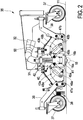
- a cleaning device according to the invention 35 is shown overall in the side view.
- it still has an outer cover and can be attached to the front of a specially designed vehicle, especially a truck.
- this is basically known from the prior art mentioned above and therefore does not need to be specified here.
- the cleaning device 35 has a chassis 36 as a kind of frame, at the corners of four wheels 37 are rotatably arranged.
- the direction of travel or movement direction of the cleaning device 35 in operation is here from right to left on the artificial turf 11.
- a downwardly projecting bottom comb 38 is provided with a plurality of resiliently mounted, downwardly facing metal tips or metal wires , This serves to larger items such as balls or the like. to push in front of them, so they do not interfere with the operation of the suction device 21.
- the artificial turf 11 can be combed and loosened so to speak, in particular a backfilling in the artificial turf 11 with the dirt particles on it and in it.
- the suction device itself is not shown in detail here, only a suction connection 31 with a suction 32 at the top in the manner of large pipes or hoses.
- a guide device 40 for the nozzle tubes 13 is shown in detail.
- the guide device 40 has a vertically movable guide carriage 41, which is movable along vertical guide rods 42, for example, by a top of the guide rods 42 patch drive. This can be a spindle drive or another drive. Also possible is a manual adjustment.
- Of the guide carriage 41 go two retaining levers 43a and 43b hingedly inclined downwards and outwards. At their lower ends they are connected to the nozzle tubes 13, namely rotatable.
- offset from the guide slide 41 is slightly offset from adjusting levers 45a and 45b parallel to the holding levers 43 from. They are rotatably connected to the ends of adjusting arms 46a and 46b, said adjusting arms 46a and 46b being rotationally connected to the nozzle pipes.
- the nozzle tubes themselves are slidably mounted in link slots 48a and 48b with slight flexing provided in link plates 47a and 47b. These link plates 47 are attached to the left and the right side of the chassis 36 or on a kind of cover box odgl ..
- the arc shape of the link slots 48 determines a path of movement of the nozzle tubes 13 during movement. If the guide carriage 41 is moved upward, as for example by comparison with the enlarged view in FIG Fig.
- the adjusting lever 45 ensure by their articulation of the adjusting arms 46 for alignment of the spray jets of the nozzle tubes or rotating the nozzle tubes 13. Since the holding lever 43 and the lever 45 are parallel to each other, the alignment of the nozzle tubes 13 and thus also their flat jet nozzles 14 and the spray jets 16 in the adjustment always the same. Otherwise this would not be guaranteed.
- the adjusting lever 45 are either adjusted, for example shortened or lengthened in length, or changed their points of articulation on the guide carriage 41 or on the adjustment arms 46 become. This can be controlled by a motor, alternatively manually.
- all the levers are rigid and length-invariant, so that when the nozzle tubes 13 move, their angle ⁇ to the artificial turf 11 remains the same.
- link slots 48 can be configured differently in the link plates 47. By replacing these link plates 47 with each other slot slots other paths of movement for the nozzle tubes can be provided. Furthermore, it could also be provided that in each case different slide slots 48 are provided for the two nozzle tubes, so that possibly the angle of their sprays to artificial turf are no longer the same or no longer change the same way.
- a treatment device 56 for disinfection or the like is at the top of the right chassis 36 a treatment device 56 for disinfection or the like.
- the treatment device 56 has a tank 58 on top, which contains the liquid for treatment or disinfection.
- the liquid can be pumped from the tank 58 to a discharge 64.
- Tank 58 and pump 62 may also be integrated as a unit.
- the discharge device 64 has a tube 65 with a plurality of discharge openings 66 thereon, which may also be formed as a kind of nozzles.
- the discharge of the liquid for treatment especially when dealing with a disinfecting liquid, does not require a certain high pressure, except to produce a spray curtain 68 for a better and more uniform distribution. So can be done after cleaning the artificial turf 11 disinfection.
- Fig. 3 From the oblique view of Fig. 3 is the outer structure of the cleaning device 35 except for a cover or the like. good to see.
- the cleaning device 35 With a solid arm 50, the cleaning device 35 is connected by means of a provided at its right end coupling plate or the like. The like on an aforementioned truck or the like. can be attached.
- four suction connections 31 are provided, of which two in each case join together to form a total of two pipes which lead to an extraction 32. This extraction is advantageously arranged on the aforementioned truck, which leads the entire cleaning device.
- a prescribed guide device 40 is provided for the nozzle tubes 13.
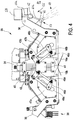
- FIG. 5 an enlarged oblique view of a suction box 27 of a suction device 21 is shown.
- the suction box 27 has inclined outer sides 28, see also the sectional view of Fig. 6 , Within the outer sides 28, the suction box 27 has two inner sides 29a and 29b, which are also slightly inclined and thus diverge slightly from bottom to top. Their angle to the horizontal is about 80 ° to 85 °. They are mainly intended to make the interior 30 slightly smaller than it would be according to the position of the outside 28. This serves to improve the effectiveness of the suction.
- the angle of the outer sides 28 is due to the desired adjustment path or movement path for the outer suction cheeks 24a and 24b.
- the suction box 27 is divided in its interior 30 by means of inclined and in angled subdivisions 54 in four areas. Although these individual areas are in width according to the section of Fig. 6 slightly widened from bottom to top, but greatly shortened in length according to the longitudinal axis of the suction box and run exactly to the suction connections 31 at the top of the suction box 27.
- the four chambers formed by the partitions 54 are completed against each other. Aspirated upwardly thrown dirt particles 19 and liquid or water are so very efficient and very efficiently sucked to the suction ports 31 out and moved and thus completely removed so that nothing falls through the suction slot 22 back down to the substrate 11.
- Fig. 6 From the oblique view of Fig. 6 can also be seen how the spray jets 16a and 16b of the flat jet nozzles 14a and 14b of the nozzle tubes 13a and 13b respectively form largely closed liquid curtains, which are relatively thin and rectified, but closed in width across the working width of the cleaning device 35. You just meet in the here also indicated impact area 18 on the artificial turf 11. It can also be seen how the suction slot 22 is here above the impact area 18.
- an adjustment of the angle ⁇ or the height or general position of the nozzle tubes 13 can also be done directly during the cleaning process for an artificial turf 11.
- an operator of the cleaning device performs some experiments to test out what the nature of the surface to be cleaned or artificial turf 11 and how much dirt it has and how much and what kind of backfill is included. Then the operator may make an adjustment.
- a control of the cleaning result by the operator is hardly possible and therefore an adjustment not particularly useful.
Landscapes
- Engineering & Computer Science (AREA)
- Architecture (AREA)
- Civil Engineering (AREA)
- Structural Engineering (AREA)
- Cleaning In General (AREA)
- Cleaning Of Streets, Tracks, Or Beaches (AREA)
- Soil Working Implements (AREA)
Applications Claiming Priority (1)
| Application Number | Priority Date | Filing Date | Title |
|---|---|---|---|
| DE102017205196.5A DE102017205196A1 (de) | 2017-03-28 | 2017-03-28 | Reinigungsvorrichtung und Vorrichtung zur Reinigung |
Publications (3)
| Publication Number | Publication Date |
|---|---|
| EP3382101A2 true EP3382101A2 (fr) | 2018-10-03 |
| EP3382101A3 EP3382101A3 (fr) | 2018-12-05 |
| EP3382101B1 EP3382101B1 (fr) | 2021-03-03 |
Family
ID=61017824
Family Applications (1)
| Application Number | Title | Priority Date | Filing Date |
|---|---|---|---|
| EP18152570.0A Active EP3382101B1 (fr) | 2017-03-28 | 2018-01-19 | Dispositif de nettoyage et procédé de nettoyage corespondant |
Country Status (2)
| Country | Link |
|---|---|
| EP (1) | EP3382101B1 (fr) |
| DE (1) | DE102017205196A1 (fr) |
Cited By (1)
| Publication number | Priority date | Publication date | Assignee | Title |
|---|---|---|---|---|
| EP3872264A1 (fr) | 2020-02-28 | 2021-09-01 | Sandmaster Gesellschaft für Spielsandpflege und Umwelthygiene mbH | Dispositif filtrant mobile et procédé de filtrage d'un liquide contaminé |
Citations (1)
| Publication number | Priority date | Publication date | Assignee | Title |
|---|---|---|---|---|
| DE102010011418A1 (de) | 2010-03-15 | 2011-09-15 | Wolfgang Seeholzer | Vorrichtung, System und Verfahren zur Reinigung von Kunstrasen |
Family Cites Families (3)
| Publication number | Priority date | Publication date | Assignee | Title |
|---|---|---|---|---|
| AT340992B (de) * | 1975-07-21 | 1978-01-10 | Ruf Anton | Waschsauger zum reinigen von verkehrsflachen |
| DE4128879A1 (de) * | 1991-08-30 | 1993-03-04 | Schoerling Waggonbau | Verfahren zur reinigung von strassenoberflaechen oder dergleichen mit einem kehrfahrzeug sowie kehrfahrzeug |
| US7290307B1 (en) * | 2004-05-27 | 2007-11-06 | Victor Chao | Implement for removing pavement cleaner |
-
2017
- 2017-03-28 DE DE102017205196.5A patent/DE102017205196A1/de not_active Withdrawn
-
2018
- 2018-01-19 EP EP18152570.0A patent/EP3382101B1/fr active Active
Patent Citations (1)
| Publication number | Priority date | Publication date | Assignee | Title |
|---|---|---|---|---|
| DE102010011418A1 (de) | 2010-03-15 | 2011-09-15 | Wolfgang Seeholzer | Vorrichtung, System und Verfahren zur Reinigung von Kunstrasen |
Cited By (1)
| Publication number | Priority date | Publication date | Assignee | Title |
|---|---|---|---|---|
| EP3872264A1 (fr) | 2020-02-28 | 2021-09-01 | Sandmaster Gesellschaft für Spielsandpflege und Umwelthygiene mbH | Dispositif filtrant mobile et procédé de filtrage d'un liquide contaminé |
Also Published As
| Publication number | Publication date |
|---|---|
| EP3382101B1 (fr) | 2021-03-03 |
| EP3382101A3 (fr) | 2018-12-05 |
| DE102017205196A1 (de) | 2018-10-04 |
Similar Documents
| Publication | Publication Date | Title |
|---|---|---|
| DE19718773B4 (de) | Lackierkopf | |
| DE3805162C2 (de) | Saugreiniger | |
| EP2835471B2 (fr) | Fraiseuse routière et procédé de fraisage et de transport du flux de matériau fraisé | |
| DE602004000708T2 (de) | Tunnelspritzgerät für Reihen von Obstgärten, Weingärten oder andere Pflanzen | |
| AT512704B1 (de) | Vorrichtung mit einer Abscheidefläche und einem beweglichen Zusatzrost zum Entfernen von Siebgut aus einer strömenden Flüssigkeit | |
| EP1552781B1 (fr) | Lave-vaisselle avec glissières d'extraction du panier. | |
| EP3382101B1 (fr) | Dispositif de nettoyage et procédé de nettoyage corespondant | |
| DE19916654A1 (de) | Trocknungsvorrichtung zum Trocknen von Fahrzeugen in Fahrzeugwaschanlagen | |
| DE10154885A1 (de) | Verfahren zur Behandlung von Gegenständen mittels einer Flüssigkeit | |
| DE2919945C2 (fr) | ||
| WO2011009917A2 (fr) | Procédé et dispositif pour nettoyer des substrats sur un support | |
| EP1884588A2 (fr) | Dispositif de nettoyage | |
| DE102007046804B4 (de) | Reinigungsvorrichtung für den Rahmen einer Koksofenkammer | |
| WO2003009945A1 (fr) | Dispositif de nettoyage d'une cellule de revetement par poudre | |
| DE102016100597B4 (de) | Vorrichtung und Verfahren zum Reinigen von Pinseln | |
| DE102016118903A1 (de) | Bürstenkopf für einen Staubsauger oder einen Saugroboter | |
| DE102007006110A1 (de) | Vorrichtung zur Profilierung eines Wegkörpers | |
| EP3613643B1 (fr) | Installation de lavage de véhicules | |
| CH674331A5 (en) | Belt type grinding machine - has two endless belts with abrasive surfaces which pass around guide rollers and pressed against workpiece by shoes | |
| EP3378369A1 (fr) | Pied à dépression pour une machine de nettoyage du sol | |
| DE2928481A1 (de) | Vorrichtung zum reinigen von drahtbehaeltern o.dgl. | |
| DE2716070C3 (de) | Vorrichtung zum Räumen von abgelagertem Strahlmittel | |
| DE3144222C2 (de) | Einrichtung zum Behandeln von Türen und Türrahmen von Horizontalkammer-Verkokungsöfen | |
| DE1652246B1 (de) | Abblasvorrichtung an einer Strahlanlage zum Entfernen von auf Walzprodukten verbliebenem Strahlmittel und Staub | |
| DE2245116C3 (de) | Vorrichtung zum Aufsprühen von Flüssigkeiten |
Legal Events
| Date | Code | Title | Description |
|---|---|---|---|
| PUAI | Public reference made under article 153(3) epc to a published international application that has entered the european phase |
Free format text: ORIGINAL CODE: 0009012 |
|
| STAA | Information on the status of an ep patent application or granted ep patent |
Free format text: STATUS: THE APPLICATION HAS BEEN PUBLISHED |
|
| AK | Designated contracting states |
Kind code of ref document: A2 Designated state(s): AL AT BE BG CH CY CZ DE DK EE ES FI FR GB GR HR HU IE IS IT LI LT LU LV MC MK MT NL NO PL PT RO RS SE SI SK SM TR |
|
| AX | Request for extension of the european patent |
Extension state: BA ME |
|
| PUAL | Search report despatched |
Free format text: ORIGINAL CODE: 0009013 |
|
| AK | Designated contracting states |
Kind code of ref document: A3 Designated state(s): AL AT BE BG CH CY CZ DE DK EE ES FI FR GB GR HR HU IE IS IT LI LT LU LV MC MK MT NL NO PL PT RO RS SE SI SK SM TR |
|
| AX | Request for extension of the european patent |
Extension state: BA ME |
|
| RIC1 | Information provided on ipc code assigned before grant |
Ipc: E01H 1/10 20060101AFI20181029BHEP |
|
| STAA | Information on the status of an ep patent application or granted ep patent |
Free format text: STATUS: REQUEST FOR EXAMINATION WAS MADE |
|
| 17P | Request for examination filed |
Effective date: 20190604 |
|
| RBV | Designated contracting states (corrected) |
Designated state(s): AL AT BE BG CH CY CZ DE DK EE ES FI FR GB GR HR HU IE IS IT LI LT LU LV MC MK MT NL NO PL PT RO RS SE SI SK SM TR |
|
| STAA | Information on the status of an ep patent application or granted ep patent |
Free format text: STATUS: EXAMINATION IS IN PROGRESS |
|
| 17Q | First examination report despatched |
Effective date: 20190801 |
|
| GRAP | Despatch of communication of intention to grant a patent |
Free format text: ORIGINAL CODE: EPIDOSNIGR1 |
|
| STAA | Information on the status of an ep patent application or granted ep patent |
Free format text: STATUS: GRANT OF PATENT IS INTENDED |
|
| INTG | Intention to grant announced |
Effective date: 20200915 |
|
| GRAS | Grant fee paid |
Free format text: ORIGINAL CODE: EPIDOSNIGR3 |
|
| RAP1 | Party data changed (applicant data changed or rights of an application transferred) |
Owner name: SANDMASTER GESELLSCHAFT FUER SPIELSANDPFLEGE UND UMWELTHYGIENE MBH |
|
| GRAA | (expected) grant |
Free format text: ORIGINAL CODE: 0009210 |
|
| STAA | Information on the status of an ep patent application or granted ep patent |
Free format text: STATUS: THE PATENT HAS BEEN GRANTED |
|
| AK | Designated contracting states |
Kind code of ref document: B1 Designated state(s): AL AT BE BG CH CY CZ DE DK EE ES FI FR GB GR HR HU IE IS IT LI LT LU LV MC MK MT NL NO PL PT RO RS SE SI SK SM TR |
|
| REG | Reference to a national code |
Ref country code: GB Ref legal event code: FG4D Free format text: NOT ENGLISH |
|
| REG | Reference to a national code |
Ref country code: CH Ref legal event code: EP Ref country code: AT Ref legal event code: REF Ref document number: 1367332 Country of ref document: AT Kind code of ref document: T Effective date: 20210315 |
|
| REG | Reference to a national code |
Ref country code: DE Ref legal event code: R096 Ref document number: 502018004086 Country of ref document: DE |
|
| REG | Reference to a national code |
Ref country code: IE Ref legal event code: FG4D Free format text: LANGUAGE OF EP DOCUMENT: GERMAN |
|
| REG | Reference to a national code |
Ref country code: NL Ref legal event code: FP |
|
| REG | Reference to a national code |
Ref country code: SE Ref legal event code: TRGR |
|
| REG | Reference to a national code |
Ref country code: LT Ref legal event code: MG9D |
|
| PG25 | Lapsed in a contracting state [announced via postgrant information from national office to epo] |
Ref country code: BG Free format text: LAPSE BECAUSE OF FAILURE TO SUBMIT A TRANSLATION OF THE DESCRIPTION OR TO PAY THE FEE WITHIN THE PRESCRIBED TIME-LIMIT Effective date: 20210603 Ref country code: LT Free format text: LAPSE BECAUSE OF FAILURE TO SUBMIT A TRANSLATION OF THE DESCRIPTION OR TO PAY THE FEE WITHIN THE PRESCRIBED TIME-LIMIT Effective date: 20210303 Ref country code: GR Free format text: LAPSE BECAUSE OF FAILURE TO SUBMIT A TRANSLATION OF THE DESCRIPTION OR TO PAY THE FEE WITHIN THE PRESCRIBED TIME-LIMIT Effective date: 20210604 Ref country code: HR Free format text: LAPSE BECAUSE OF FAILURE TO SUBMIT A TRANSLATION OF THE DESCRIPTION OR TO PAY THE FEE WITHIN THE PRESCRIBED TIME-LIMIT Effective date: 20210303 Ref country code: FI Free format text: LAPSE BECAUSE OF FAILURE TO SUBMIT A TRANSLATION OF THE DESCRIPTION OR TO PAY THE FEE WITHIN THE PRESCRIBED TIME-LIMIT Effective date: 20210303 Ref country code: NO Free format text: LAPSE BECAUSE OF FAILURE TO SUBMIT A TRANSLATION OF THE DESCRIPTION OR TO PAY THE FEE WITHIN THE PRESCRIBED TIME-LIMIT Effective date: 20210603 |
|
| PG25 | Lapsed in a contracting state [announced via postgrant information from national office to epo] |
Ref country code: PL Free format text: LAPSE BECAUSE OF FAILURE TO SUBMIT A TRANSLATION OF THE DESCRIPTION OR TO PAY THE FEE WITHIN THE PRESCRIBED TIME-LIMIT Effective date: 20210303 Ref country code: LV Free format text: LAPSE BECAUSE OF FAILURE TO SUBMIT A TRANSLATION OF THE DESCRIPTION OR TO PAY THE FEE WITHIN THE PRESCRIBED TIME-LIMIT Effective date: 20210303 Ref country code: RS Free format text: LAPSE BECAUSE OF FAILURE TO SUBMIT A TRANSLATION OF THE DESCRIPTION OR TO PAY THE FEE WITHIN THE PRESCRIBED TIME-LIMIT Effective date: 20210303 |
|
| PG25 | Lapsed in a contracting state [announced via postgrant information from national office to epo] |
Ref country code: SM Free format text: LAPSE BECAUSE OF FAILURE TO SUBMIT A TRANSLATION OF THE DESCRIPTION OR TO PAY THE FEE WITHIN THE PRESCRIBED TIME-LIMIT Effective date: 20210303 Ref country code: EE Free format text: LAPSE BECAUSE OF FAILURE TO SUBMIT A TRANSLATION OF THE DESCRIPTION OR TO PAY THE FEE WITHIN THE PRESCRIBED TIME-LIMIT Effective date: 20210303 Ref country code: CZ Free format text: LAPSE BECAUSE OF FAILURE TO SUBMIT A TRANSLATION OF THE DESCRIPTION OR TO PAY THE FEE WITHIN THE PRESCRIBED TIME-LIMIT Effective date: 20210303 |
|
| PG25 | Lapsed in a contracting state [announced via postgrant information from national office to epo] |
Ref country code: PT Free format text: LAPSE BECAUSE OF FAILURE TO SUBMIT A TRANSLATION OF THE DESCRIPTION OR TO PAY THE FEE WITHIN THE PRESCRIBED TIME-LIMIT Effective date: 20210705 Ref country code: RO Free format text: LAPSE BECAUSE OF FAILURE TO SUBMIT A TRANSLATION OF THE DESCRIPTION OR TO PAY THE FEE WITHIN THE PRESCRIBED TIME-LIMIT Effective date: 20210303 Ref country code: SK Free format text: LAPSE BECAUSE OF FAILURE TO SUBMIT A TRANSLATION OF THE DESCRIPTION OR TO PAY THE FEE WITHIN THE PRESCRIBED TIME-LIMIT Effective date: 20210303 Ref country code: IS Free format text: LAPSE BECAUSE OF FAILURE TO SUBMIT A TRANSLATION OF THE DESCRIPTION OR TO PAY THE FEE WITHIN THE PRESCRIBED TIME-LIMIT Effective date: 20210703 |
|
| REG | Reference to a national code |
Ref country code: DE Ref legal event code: R097 Ref document number: 502018004086 Country of ref document: DE |
|
| PLBE | No opposition filed within time limit |
Free format text: ORIGINAL CODE: 0009261 |
|
| STAA | Information on the status of an ep patent application or granted ep patent |
Free format text: STATUS: NO OPPOSITION FILED WITHIN TIME LIMIT |
|
| PG25 | Lapsed in a contracting state [announced via postgrant information from national office to epo] |
Ref country code: ES Free format text: LAPSE BECAUSE OF FAILURE TO SUBMIT A TRANSLATION OF THE DESCRIPTION OR TO PAY THE FEE WITHIN THE PRESCRIBED TIME-LIMIT Effective date: 20210303 Ref country code: DK Free format text: LAPSE BECAUSE OF FAILURE TO SUBMIT A TRANSLATION OF THE DESCRIPTION OR TO PAY THE FEE WITHIN THE PRESCRIBED TIME-LIMIT Effective date: 20210303 Ref country code: AL Free format text: LAPSE BECAUSE OF FAILURE TO SUBMIT A TRANSLATION OF THE DESCRIPTION OR TO PAY THE FEE WITHIN THE PRESCRIBED TIME-LIMIT Effective date: 20210303 |
|
| 26N | No opposition filed |
Effective date: 20211206 |
|
| PG25 | Lapsed in a contracting state [announced via postgrant information from national office to epo] |
Ref country code: SI Free format text: LAPSE BECAUSE OF FAILURE TO SUBMIT A TRANSLATION OF THE DESCRIPTION OR TO PAY THE FEE WITHIN THE PRESCRIBED TIME-LIMIT Effective date: 20210303 |
|
| PG25 | Lapsed in a contracting state [announced via postgrant information from national office to epo] |
Ref country code: IT Free format text: LAPSE BECAUSE OF FAILURE TO SUBMIT A TRANSLATION OF THE DESCRIPTION OR TO PAY THE FEE WITHIN THE PRESCRIBED TIME-LIMIT Effective date: 20210303 |
|
| PG25 | Lapsed in a contracting state [announced via postgrant information from national office to epo] |
Ref country code: IS Free format text: LAPSE BECAUSE OF FAILURE TO SUBMIT A TRANSLATION OF THE DESCRIPTION OR TO PAY THE FEE WITHIN THE PRESCRIBED TIME-LIMIT Effective date: 20210703 |
|
| PG25 | Lapsed in a contracting state [announced via postgrant information from national office to epo] |
Ref country code: MC Free format text: LAPSE BECAUSE OF FAILURE TO SUBMIT A TRANSLATION OF THE DESCRIPTION OR TO PAY THE FEE WITHIN THE PRESCRIBED TIME-LIMIT Effective date: 20210303 |
|
| REG | Reference to a national code |
Ref country code: CH Ref legal event code: PL |
|
| GBPC | Gb: european patent ceased through non-payment of renewal fee |
Effective date: 20220119 |
|
| PG25 | Lapsed in a contracting state [announced via postgrant information from national office to epo] |
Ref country code: LU Free format text: LAPSE BECAUSE OF NON-PAYMENT OF DUE FEES Effective date: 20220119 Ref country code: GB Free format text: LAPSE BECAUSE OF NON-PAYMENT OF DUE FEES Effective date: 20220119 |
|
| PG25 | Lapsed in a contracting state [announced via postgrant information from national office to epo] |
Ref country code: LI Free format text: LAPSE BECAUSE OF NON-PAYMENT OF DUE FEES Effective date: 20220131 Ref country code: CH Free format text: LAPSE BECAUSE OF NON-PAYMENT OF DUE FEES Effective date: 20220131 |
|
| PG25 | Lapsed in a contracting state [announced via postgrant information from national office to epo] |
Ref country code: IE Free format text: LAPSE BECAUSE OF NON-PAYMENT OF DUE FEES Effective date: 20220119 |
|
| PG25 | Lapsed in a contracting state [announced via postgrant information from national office to epo] |
Ref country code: HU Free format text: LAPSE BECAUSE OF FAILURE TO SUBMIT A TRANSLATION OF THE DESCRIPTION OR TO PAY THE FEE WITHIN THE PRESCRIBED TIME-LIMIT; INVALID AB INITIO Effective date: 20180119 |
|
| PG25 | Lapsed in a contracting state [announced via postgrant information from national office to epo] |
Ref country code: MK Free format text: LAPSE BECAUSE OF FAILURE TO SUBMIT A TRANSLATION OF THE DESCRIPTION OR TO PAY THE FEE WITHIN THE PRESCRIBED TIME-LIMIT Effective date: 20210303 Ref country code: CY Free format text: LAPSE BECAUSE OF FAILURE TO SUBMIT A TRANSLATION OF THE DESCRIPTION OR TO PAY THE FEE WITHIN THE PRESCRIBED TIME-LIMIT Effective date: 20210303 |
|
| PG25 | Lapsed in a contracting state [announced via postgrant information from national office to epo] |
Ref country code: MT Free format text: LAPSE BECAUSE OF FAILURE TO SUBMIT A TRANSLATION OF THE DESCRIPTION OR TO PAY THE FEE WITHIN THE PRESCRIBED TIME-LIMIT Effective date: 20210303 |
|
| PG25 | Lapsed in a contracting state [announced via postgrant information from national office to epo] |
Ref country code: TR Free format text: LAPSE BECAUSE OF FAILURE TO SUBMIT A TRANSLATION OF THE DESCRIPTION OR TO PAY THE FEE WITHIN THE PRESCRIBED TIME-LIMIT Effective date: 20210303 |
|
| PGFP | Annual fee paid to national office [announced via postgrant information from national office to epo] |
Ref country code: NL Payment date: 20260121 Year of fee payment: 9 |
|
| PGFP | Annual fee paid to national office [announced via postgrant information from national office to epo] |
Ref country code: SE Payment date: 20260121 Year of fee payment: 9 |
|
| PGFP | Annual fee paid to national office [announced via postgrant information from national office to epo] |
Ref country code: DE Payment date: 20260127 Year of fee payment: 9 |
|
| PGFP | Annual fee paid to national office [announced via postgrant information from national office to epo] |
Ref country code: AT Payment date: 20260119 Year of fee payment: 9 |
|
| PGFP | Annual fee paid to national office [announced via postgrant information from national office to epo] |
Ref country code: BE Payment date: 20260121 Year of fee payment: 9 |
|
| PGFP | Annual fee paid to national office [announced via postgrant information from national office to epo] |
Ref country code: FR Payment date: 20260123 Year of fee payment: 9 |