EP3382111A2 - Keramisches becken - Google Patents
Keramisches becken Download PDFInfo
- Publication number
- EP3382111A2 EP3382111A2 EP18161283.9A EP18161283A EP3382111A2 EP 3382111 A2 EP3382111 A2 EP 3382111A2 EP 18161283 A EP18161283 A EP 18161283A EP 3382111 A2 EP3382111 A2 EP 3382111A2
- Authority
- EP
- European Patent Office
- Prior art keywords
- basin
- spigot
- adaptor
- bore
- bowl
- Prior art date
- Legal status (The legal status is an assumption and is not a legal conclusion. Google has not performed a legal analysis and makes no representation as to the accuracy of the status listed.)
- Withdrawn
Links
- 239000000919 ceramic Substances 0.000 title claims abstract description 13
- 239000002699 waste material Substances 0.000 claims abstract description 48
- 238000004519 manufacturing process Methods 0.000 claims description 9
- 238000000034 method Methods 0.000 claims description 8
- 229910010293 ceramic material Inorganic materials 0.000 claims description 4
- 230000007704 transition Effects 0.000 claims description 3
- XLYOFNOQVPJJNP-UHFFFAOYSA-N water Substances O XLYOFNOQVPJJNP-UHFFFAOYSA-N 0.000 description 13
- 239000002351 wastewater Substances 0.000 description 12
- 238000009434 installation Methods 0.000 description 4
- 239000004033 plastic Substances 0.000 description 4
- 229920003023 plastic Polymers 0.000 description 4
- 239000000654 additive Substances 0.000 description 3
- 230000000996 additive effect Effects 0.000 description 3
- 238000004140 cleaning Methods 0.000 description 3
- 239000004433 Thermoplastic polyurethane Substances 0.000 description 2
- 238000012986 modification Methods 0.000 description 2
- 230000004048 modification Effects 0.000 description 2
- 229920002803 thermoplastic polyurethane Polymers 0.000 description 2
- 239000011800 void material Substances 0.000 description 2
- BQCADISMDOOEFD-UHFFFAOYSA-N Silver Chemical compound [Ag] BQCADISMDOOEFD-UHFFFAOYSA-N 0.000 description 1
- 230000000845 anti-microbial effect Effects 0.000 description 1
- 239000004599 antimicrobial Substances 0.000 description 1
- 238000010276 construction Methods 0.000 description 1
- 230000003670 easy-to-clean Effects 0.000 description 1
- 230000000694 effects Effects 0.000 description 1
- 238000003780 insertion Methods 0.000 description 1
- 230000037431 insertion Effects 0.000 description 1
- 238000011900 installation process Methods 0.000 description 1
- 238000000465 moulding Methods 0.000 description 1
- 230000008569 process Effects 0.000 description 1
- 230000000717 retained effect Effects 0.000 description 1
- 229910052709 silver Inorganic materials 0.000 description 1
- 239000004332 silver Substances 0.000 description 1
Images






Classifications
-
- E—FIXED CONSTRUCTIONS
- E03—WATER SUPPLY; SEWERAGE
- E03C—DOMESTIC PLUMBING INSTALLATIONS FOR FRESH WATER OR WASTE WATER; SINKS
- E03C1/00—Domestic plumbing installations for fresh water or waste water; Sinks
- E03C1/12—Plumbing installations for waste water; Basins or fountains connected thereto; Sinks
- E03C1/18—Sinks, whether or not connected to the waste-pipe
- E03C1/182—Sinks, whether or not connected to the waste-pipe connected to the waste-pipe
-
- E—FIXED CONSTRUCTIONS
- E03—WATER SUPPLY; SEWERAGE
- E03C—DOMESTIC PLUMBING INSTALLATIONS FOR FRESH WATER OR WASTE WATER; SINKS
- E03C1/00—Domestic plumbing installations for fresh water or waste water; Sinks
- E03C1/12—Plumbing installations for waste water; Basins or fountains connected thereto; Sinks
- E03C1/14—Wash-basins connected to the waste-pipe
-
- E—FIXED CONSTRUCTIONS
- E03—WATER SUPPLY; SEWERAGE
- E03C—DOMESTIC PLUMBING INSTALLATIONS FOR FRESH WATER OR WASTE WATER; SINKS
- E03C1/00—Domestic plumbing installations for fresh water or waste water; Sinks
- E03C1/12—Plumbing installations for waste water; Basins or fountains connected thereto; Sinks
- E03C1/32—Holders or supports for basins
- E03C1/33—Fastening sinks or basins in an apertured support
Definitions
- the present invention relates to a ceramic basin, a basin assembly, a method of installing a basin assembly, and a method of manufacturing a basin.
- a known basin assembly is shown in Fig. 1 in sectional view.
- a ceramic basin 1 has a bowl 100 and a back outlet 101 for transporting waste water from the bowl 100.
- the basin assembly also includes a trap 102 which receives waste water from the waste outlet 101 via rigid plastic pipe 103.
- the trap 102 may be connected to a waste pipe (not shown).
- the ceramic basin 1 is formed in a mould using a mould part to form the bore of the waste outlet 101, and that mould part tapers in the direction of its insertion from the rear of the basin.
- the mould part produces a downward step 104 in the waste outlet 101 which, in conjunction an upward step 105 at the entrance to the pipe 103, means that there is a depression 106 in which dirt may become trapped.
- the mould part extends in the direction 107, it has a tip which, in conjunction with the mould part(s) that form the bowl 100, may result in a surface discontinuity (a dip or a joint) in the floor 108 at the entrance to the waste outlet 101. Such a surface discontinuity may cause poor drainage from the bowl 100.
- the pipe 103 is rigid, there can be difficulty when fixing the basin 1 to the front of a panel.
- the pipe 103 needs to extend through a hole in the panel from the rear of the panel to the front of the panel. If the pipe 103 is installed before the basin 1 is fixed to the panel, the installer must connect the pipe 103 to the basin 1 when fixing the basin in position, and access to the pipe 103 for this purpose can be difficult. If the basin 1 is installed first, the installer must then gain access to the back of the panel to fix in position the pipe 103 and to extend the end of the pipe 103 through the hole in the panel to seal against the outlet hole of the back outlet 101 of the basin 1. Again, this can be difficult for the installer to accomplish.
- a ceramic basin having a bowl and a waste outlet leading from the bowl, wherein: the waste outlet is a back outlet; and the waste outlet comprises a spigot.
- an adaptor may be fitted to the basin to connect the waste outlet to a trap.
- the spigot projects rearwardly from a rear wall of the bowl.
- the basin is of the back outlet type.
- a back outlet basin may not need a plug, but may be provided with a grate or grid at the entrance to the waste outlet which is removable when the basin is being cleaned.
- a bore of the spigot has a first, proximal end at a waste hole of the bowl and a second, distal end at an outlet hole of the spigot.
- the lowest point of the bowl may lead directly into the inlet end of the bore of the spigot.
- the bore of the spigot is smooth and step-free. This helps to prevent dirt from lingering in the waste outlet of the basin and also makes the basin easier to clean.
- the bore of the spigot tapers (continuously and without steps) in the direction from the first end to the second end of the bore. This tapering in the flow direction of the waste water helps the flow of the waste water.
- the outlet hole of the spigot is circular.
- the free end of the spigot may be circular, and this helps with the fitting and adjustment of an adaptor being fitted onto the free end of the spigot because the adaptor may be easily fitted and then rotated on the spigot to the correct, desired final orientation.
- the waste hole of the bowl (the inlet hole of the waste outlet) is circular.
- the waste hole of the bowl is non-circular.
- the waste hole of the bowl may be generally triangular, and the bore of the spigot may transition from being generally triangular at its first end to being circular at its second end. With an apex of the generally triangular shape at the bottom, the configuration gives an increased speed of waste water flow for a given volumetric flow rate.
- the circle of the circular second end of the bore has a size which fits inside the generally triangular shape of the first end of the bore. This enables a mould part which forms the bore of the spigot to be withdrawn into the mould when the basin is being manufactured.
- the spigot has a smooth, step-free outer wall surface adjacent to the free end of the spigot. This may help to facilitate fitting (a socket end of) an adaptor onto the outer surface of the free end of the spigot.
- the spigot comprises a tubular wall.
- a simple tubular wall projecting back from, for example, the rear wall of the bowl has a simple construction and is easy to manufacture.
- the free end of the spigot stops short of a rear face of the basin.
- the spigot may be protected from knocks and potential damage prior to installation of the basin as the spigot is sheltered inside the overall volume or shape of the basin.
- a basin assembly comprising: a ceramic basin having a bowl and a waste outlet leading from the bowl, wherein the waste outlet comprises a spigot; and a flexible adaptor having a first, proximal end which is arranged to fit onto the spigot and a second, distal end which is connectable to a trap.
- a flexible adaptor facilitates installation of the basin as the adaptor may be flexed and manipulated during the installation process of the basin and the adaptor.
- the waste outlet is a back outlet leading from the back of the bowl.
- the flexible adaptor comprises a flexible moulded pipe.
- first (e.g. front) end of the adaptor and a central (e.g. curved) section of the adaptor may be provided by the moulded pipe.
- the second (e.g. rear) end of the adaptor may be provided by a rigid plastic threaded connector ring.
- the moulded pipe may be given a non-white (e.g. blue) colour to make it easier for the installer to see the pipe and to manipulate the pipe because the pipe will be visually distinctive compared with the other main components in the vicinity (e.g. the basin and a trap) which are often white in colour.
- a non-white colour e.g. blue
- a bore of the flexible adaptor includes an internal abutment at the first end of the flexible adaptor for abutting against an end face of the spigot. This helps to give the installer a tactile feel for when the first end of the adaptor has been fully pushed on to the spigot to provide the correct amount of overlap of the first end of the adaptor on the external surface of the spigot. The correct amount of overlap helps to provide a satisfactory seal between the adaptor and the spigot.
- the internal abutment at the first end of the flexible adaptor is provided at only the top of the bore of the flexible adaptor, and the opposite, bottom part of the bore is smooth and step free (free of an upward step).
- the surface over which the waste water flows does not have an upward step which might trap dirt.
- the internal abutment is a moulded abutment of the pipe. This is a convenient way in which to provide the abutment in the flexible adaptor.
- the basin assembly may further comprise a clamp positioned at the first end of the flexible adaptor for clamping the first end of the flexible adaptor to the spigot.
- the clamp may be a circumferential clamp incorporating means for reducing the length of the circumference of the clamp to produce a clamping effect.
- Such means may be, for example, a butterfly type rotatable knob or a thumbwheel which the installer may rotate to tighten up the clamp, and this may be done by feel by the installer without having to have sight of the clamp itself.
- the spigot projects rearwardly from a rear bowl wall.
- the spigot has a smooth, step-free bore.
- the bore of the spigot has a first, proximal end at a waste hole of the bowl and a second, distal end; and the bore of the spigot tapers in the direction from the first end to the second end of the bore.
- the spigot has a smooth, step-free outer wall surface adjacent to (at least) the free end of the spigot.
- the entire (generally cylindrical) outer surface of the spigot is smooth and step-free.
- the spigot comprises a tubular wall. Such a spigot shape facilitates the manufacture of the spigot during the moulding process to produce the basin.
- the adaptor has a first (normal or un-flexed) state in which a central section of the adaptor is curved between the first and second ends of the adaptor; and the adaptor has a second (flexed or temporary) state in which the central section of the adaptor is less curved between the first and second ends of the adaptor.
- a method of installing a basin assembly comprising the steps of: fitting a flexible adaptor to a spigot of a ceramic basin; with the adaptor in a flexed state, inserting the adaptor through a hole in a panel; allowing the adaptor to return to an unflexed state; securing the basin to the panel; and fitting a trap to a free end of the adaptor.
- a method of manufacturing a ceramic basin having a bowl and a waste outlet by using a multi-part mould comprising the steps of: setting up the mould including positioning a first mould part which is tapered and which is for forming a bore of a spigot of the waste outlet of the basin; introducing ceramic material into the mould; and, after the ceramic material has set sufficiently to give the basin a stable shape, disassembling the mould including removing the first mould part into the bowl of the basin.
- Such a manufacturing method may be used to produce a basin without locations in the bore of the spigot in which dirt may become trapped.
- the first mould part also forms part of the floor of the bowl of the basin adjacent to the bore of the spigot. This eliminates surface discontinuities in the vicinity of the entrance to the spigot bore which might disrupt or slow the flow of waste water into the spigot bore.
- an anti-microbial additive e.g. silver based
- an additive may be included in a two-layer glaze.
- an additive may be incorporated in or applied to the internal surfaces of the pipe.
- Fig. 1 is a sectional view of a prior art basin assembly.
- Fig. 2 shows, in diagrammatic form, a sectional view of an embodiment of a basin assembly in accordance with the present invention.
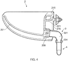
- the basin assembly comprises a moulded ceramic basin 2 and a flexible adaptor 3.
- the basin 2 has a bowl 201 defined by a front and side inner (bowl) wall 202 and a rear bowl wall 203.
- the basin also has a front and side outer (basin) wall 204 with a void 205 between the inner and outer walls 202, 204.
- the bowl 201 may include an anti-splash fin such as a front-to-back anti-splash fin 206.
- the basin 2 is of the back outlet type and includes a (back) waste outlet 207 for draining waste water from the bowl 201.
- the waste outlet 207 is in the form of a projection having a male shape.
- the waste outlet 207 comprises a spigot 208 which has a central longitudinal bore 209 having a first end 210 (proximal to the bowl 201) and a second end 211 (distal from the bowl 201).
- the first end 210 provides a waste hole 212 of the bowl 201, and the second end 211 provides an outlet hole 213 of the spigot 208.
- the bore 209 tapers in the direction 214 which is the flow direction of the waste water. If the holes 212, 213 are circular, the diameter of the hole 212 is greater than the diameter of the hole 213. During manufacture of the basin 2, this facilitates withdrawal of a mould part into the bowl 201 as will be described later.
- the basin 2 includes a rear top deck 215 (a tap deck) on which taps may be mounted.
- a rear face 216 may be mounted flush against a vertical panel during installation of the basin to the panel.
- the rear (free) end 217 of the spigot 208 includes a circular end face 218 around the outlet hole 213 which functions as an abutment for the flexible adaptor 3 as will be described later.
- the spigot 208 comprises a circumferential (tubular) wall 219 and the inner surface of the wall 219 provides the slightly tapered bore 209, and the outer surface 220 provides a circumferential male surface onto which a female socket portion of the flexible adaptor 3 may be clamped as will be described later.
- the basin 2 includes spacing structure 221 for spacing the rear bowl wall 203 away from the rear face 216 of the basin 2, and the spacing structure 221 may be in the form of, for example, webs which extend in the front to rear direction. These webs may leave a centrally located void underneath the tap deck 215 in which the spigot 208 is positioned.
- the flexible adaptor 3 comprises a flexible moulded pipe 301 having a first end 302 which functions as a female component (a socket) for receiving the male shape of the spigot 208.
- the pipe 301 also has a second end 303 onto which is moulded a rigid plastic threaded connector ring 304.
- a bore 305 runs through the pipe 301 from the first end 302 to the second end 303.
- the bore 305 is not rotationally symmetric in shape.
- the upper part of the bore 305 at the first end 302 incorporates an abutment 306 in the form of a step portion which reduces the diameter of the bore 305 in the water flow direction.
- the inner surface of the pipe 301 is smooth and step free.
- the pipe 301 may be moulded from TPU (thermoplastic polyurethane) having the desired degree of flexibility.
- the flexible adaptor 3 also includes a circumferential clamp 308 (a pipe clamp or hose clamp) for clamping the socket of the first end 302 of the pipe 301 onto the ceramic spigot 208, as will be described later.
- the clamp 308 includes rotatable means 309 for tightening up (reducing the circumference of) the main, circumferential clamping portion of the clamp.
- the function of the connector ring 304 at the second (distal) end 303 of the pipe 301 is to enable the adaptor to be connected to a suitable trap or trapway 4 which is made of rigid plastic and has a threaded proximal end 401 onto which the connector ring 304 may be screwed.
- the trap 4 may include a valve 402 so as to be of the anti-syphon type.
- a distal end 403 may also be threaded and is connectable to a downstream waste water pipe 5.
- FIG. 3 is a perspective view of a section through a first version of the basin assembly (wherein the basin 2 does include an anti-splash fin 206).
- Fig. 4 is a side view of a section through a second version of the basin assembly (wherein the basin 2 does not include an anti-splash fin).
- Fig. 5 is an enlargement of the flexible adaptor 3 shown in Fig. 4 .
- the clamp 308 is omitted from the flexible adaptor 3 for reasons of clarity.
- abutment 306 of the moulded pipe 301 abuts against the end face 218 of the spigot 208. This abutment determines how far the moulded pipe 301 may be pushed onto the spigot 208.
- the water flow path from the bowl 201 along the waste outlet 207 and along the pipe 301 involves smooth water flow with one step down (at the end of the waste outlet 207). There are no steps up which might trap dirt.
- the pipe 301 starts off with a relatively large internal diameter (at its first end 302) and the internal diameter steadily reduces towards the second end 303.
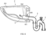
- Fig. 6 is a sectional view of the basin assembly shown in Fig. 3 , but in Fig. 6 there is a diagrammatic indication of how a mould part 6 may, in the manufacturing process of the basin 2, be withdrawn into the bowl 201 after the basin 2 has been formed in an overall mould which includes the mould part 6 and other relevant mould parts.
- the mould part 6 includes a first portion 601 which is tapered and which forms the shape of the tapered bore 209 of the spigot 208, and a second portion 602 which forms a part of the bottom surface (the floor) of the bowl 201 adjacent to the entrance to the waste hole 212.
- Fig. 7 is a perspective view of a basin in accordance with the present invention which has a non-circular waste hole 212.
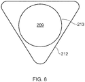
- Fig. 8 is a diagrammatic representation of how the waste hole 212 (which is generally triangular) is bigger than the outlet hole 213 at the exit of the bore 209 of the spigot 208.
- the outlet hole 213 fits within the outline of the shape of the waste hole 212.
- This enables a tapered mould part (of the same general style as the mould part 6 of Fig. 6 ) to be used to form the bore 209 with its non-circular entrance hole (the generally triangular waste hole 212).
- the generally triangular shape at the entrance enables increased speed of water flow for a given volumetric flow rate, because the water is concentrated in the bottommost apex of the triangular shape.
- the outlet hole 213 is retained as having a circular shape so that the free end 217 of the spigot 208 may remain circular, which facilities fitting the moulded pipe 301 onto the spigot 208 and then rotationally adjusting the orientation of the pipe 301 on the spigot 208 by twisting the pipe 301 into the desired, final position.
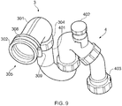
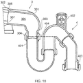
- Fig. 9 is a perspective view of just the flexible adaptor 3 and the trap 4 of the basin assembly of Fig. 3 .
- the clamp 308 and its tightening means 309 are shown.
- Fig. 10 is a sectional view through the flexible adaptor 3 and the trap 4 of Fig. 9 and shows that the water level 404 of the trap 4 is arranged to be at or just above the junction between the proximal end 401 of the trap 4 and the second, distal end 303 of the moulded pipe 301.
- Figs. 11A to 11D show a sequence of steps for fitting an embodiment of a basin assembly in accordance with the present invention onto a vertical panel 7.
- Fig. 11A before the basin 2 is fitted to the panel 7, the flexible adaptor 3 is pushed onto the spigot 208 of the basin 2.
- the flexible adaptor 3 is pushed on until the abutment 306 of the flexible pipe 301 abuts against the end face 218 of the free end 217 of the spigot 208.
- the pipe 301 is rotated (twisted) on the spigot 208 until the connector ring 304 at the second end 303 of the pipe 301 is generally horizontal.
- the clamp 308 is then tightened by rotating the tightening means 309 to lock the pipe 301 in position on the spigot 208.
- the installer may then check the water-tightness of the seal between the pipe 301 and the spigot 208.
- Fig. 11B the basin assembly is offered up to the panel 7.
- Mounting studs 222 projecting rearwardly from the rear face 216 of the basin 2 are passed through holes 701 which have been pre-drilled in the panel 7.
- the panel 7 also has a hole 702 pre-drilled (e.g. with a 79mm diameter) between the holes 701.
- the hole 702 is for receiving the adaptor 3, but in order for this to happen the flexible pipe 301 must be flexed upwards (see arrow 310) to give the pipe 301 a flexed (e.g. generally horizontal) state or configuration.
- the connector ring 304 and the second end 303 of the adaptor may then pass through the hole 702.
- the flexing of the pipe 301 may then be released, and the pipe 301 returns to its original (un-flexed) state or configuration (as in Fig. 11A ).
- washers 223 and nuts 224 are fitted onto the studs 222 to hold the basin 2 in position on the panel 7.
- the trap 4 is fitted to the flexible adaptor 3 by screwing the connector ring 304 of the adaptor 3 onto the proximal end 401 of the trap 4.
- the trap 4 is of the adjustable type having rotatable sections, and (as shown in Fig. 11D ) the trap 4 may now be adjusted to suit the positioning of the waste water pipe 5 to which the trap 4 is to be connected.
- Figs. 12A to 12D show possible alternative shapes for the waste hole 212.
- the circular shape of Fig. 12A benefits from known water flow characteristics.
- the settling area for dirt at the bottom of the shape is small, and the shape is easy to clean with a finger.
- the generally triangular shape of Fig. 12B (inverted, rounded triangle shape) has a smaller area than the round shape of Fig. 12A for dirt to settle at the bottom of the shape. It has a higher flow speed than the shape of Fig. 12A for a given volumetric flow rate, and this improves the self-cleaning function. As the volumetric flow rate increases, the water level rises and the constantly increasing width of the shape can accommodate the increase in flow rate. The shape is good at generating turbulence in the water flow, which helps with the self-cleaning function.
- the elliptical shape of Fig. 12C has a high and smooth flow characteristic, which helps with the speed of drainage of the bowl 201 because, even at low volumetric flow rates, the available width is large for carrying the water flow.
- the slot shape (horizontal slot with rounded ends) of Fig. 12D improves on the speed of drainage of the elliptical shape of Fig. 12C , and offers easy access for cleaning across the full width of the slot shape.
- the (inlet) shape of the waste hole 212 would transition, along the length of the bore 209, to the circular (outlet) shape of the outlet hole 213.
Landscapes
- Engineering & Computer Science (AREA)
- Environmental & Geological Engineering (AREA)
- Health & Medical Sciences (AREA)
- Life Sciences & Earth Sciences (AREA)
- Hydrology & Water Resources (AREA)
- Public Health (AREA)
- Water Supply & Treatment (AREA)
- Sewage (AREA)
- Joints Allowing Movement (AREA)
Applications Claiming Priority (1)
| Application Number | Priority Date | Filing Date | Title |
|---|---|---|---|
| GB1703895.1A GB2561337A (en) | 2017-03-10 | 2017-03-10 | Basin |
Publications (2)
| Publication Number | Publication Date |
|---|---|
| EP3382111A2 true EP3382111A2 (de) | 2018-10-03 |
| EP3382111A3 EP3382111A3 (de) | 2018-12-19 |
Family
ID=58605451
Family Applications (1)
| Application Number | Title | Priority Date | Filing Date |
|---|---|---|---|
| EP18161283.9A Withdrawn EP3382111A3 (de) | 2017-03-10 | 2018-03-12 | Keramisches becken |
Country Status (2)
| Country | Link |
|---|---|
| EP (1) | EP3382111A3 (de) |
| GB (1) | GB2561337A (de) |
Families Citing this family (1)
| Publication number | Priority date | Publication date | Assignee | Title |
|---|---|---|---|---|
| DE102023130203A1 (de) * | 2023-11-01 | 2025-05-08 | Universitätsklinikum Jena | Waschbecken |
Family Cites Families (12)
| Publication number | Priority date | Publication date | Assignee | Title |
|---|---|---|---|---|
| DE1609107A1 (de) * | 1965-10-08 | 1970-07-30 | Kera Werke Ag | Sanitaerer Apparat,wie Waschbecken,Spuelbecken,Bidet u.dgl.mit keramischem Siphon |
| DE1253794B (de) * | 1965-11-25 | 1967-11-09 | Zeiss Carl Fa | Vorrichtung zur Fernverstellung von Mess- oder Arbeitstischen |
| DE7231936U (de) * | 1971-09-07 | 1973-09-20 | Contessi G | Waschvorrichtung mit ausserhalb ihres beckens angeordneter abflussarmatur |
| US3913928A (en) * | 1973-05-09 | 1975-10-21 | Seiichi Yamaguchi | Resilient joint |
| DE2334572C2 (de) * | 1973-07-07 | 1975-07-03 | Friedrichsfeld Gmbh Steinzeugund Kunststoffwerke, 6800 Mannheim | Verfahren zum Herstellen eines Keramik-Labor-Beckens und Labor-Becken, hergestellt nach diesem Verfahren |
| BE1008069A3 (nl) * | 1994-02-09 | 1996-01-09 | Ericson Kurt Sture Birger | Sanitair toestel met indirekte afvoer. |
| DE19547620A1 (de) * | 1995-12-20 | 1997-06-26 | Villeroy & Boch | Keramisches Sanitärteil |
| JPH11200444A (ja) * | 1998-01-14 | 1999-07-27 | Daiken Trade & Ind Co Ltd | 流し台 |
| DE20019579U1 (de) * | 2000-11-15 | 2001-02-01 | Scherer, Norbert, 66773 Schwalbach | Beckenablauf |
| JP2007032022A (ja) * | 2005-07-25 | 2007-02-08 | Janis Ltd | 水洗器 |
| WO2010029136A1 (en) * | 2008-09-12 | 2010-03-18 | Karine Zoons | Removable washing basin |
| CN203640013U (zh) * | 2013-11-20 | 2014-06-11 | 九牧厨卫股份有限公司 | 一种面盆 |
-
2017
- 2017-03-10 GB GB1703895.1A patent/GB2561337A/en not_active Withdrawn
-
2018
- 2018-03-12 EP EP18161283.9A patent/EP3382111A3/de not_active Withdrawn
Also Published As
| Publication number | Publication date |
|---|---|
| GB2561337A (en) | 2018-10-17 |
| EP3382111A3 (de) | 2018-12-19 |
| GB201703895D0 (en) | 2017-04-26 |
Similar Documents
| Publication | Publication Date | Title |
|---|---|---|
| AU2009200296B2 (en) | Spa fittings | |
| US11668085B2 (en) | Rim jet nozzle system for toilets | |
| CN111663621A (zh) | 马桶形式的卫生设备 | |
| DE9108260U1 (de) | Ablaufanschluß an einem Sanitärartikel | |
| CN108421651A (zh) | 花洒 | |
| CN104114782A (zh) | 用于盥洗台的弹跳装置的设置构件以及设置方法 | |
| GB2561337A (en) | Basin | |
| KR101789940B1 (ko) | 수전 연결식 구강세정기 | |
| EP3064663A1 (de) | Sanitäreinrichtung | |
| US6623045B2 (en) | Fastening device for fitting parts | |
| EP1953439A2 (de) | Anordnung zum Anschluss eines flexiblen Wasserrohrs | |
| JP7603253B2 (ja) | 排水ユニット | |
| JP7114023B2 (ja) | 水栓装置 | |
| CN216867645U (zh) | 一种穿管龙头 | |
| JP6381237B2 (ja) | 配管カバー、その取り付け方法及び水栓 | |
| CN108474204A (zh) | 冲洗装置 | |
| GB2409009A (en) | A telescopic connection structure | |
| CH714828A2 (de) | Toilette. | |
| JP2023155479A (ja) | 水洗大便器 | |
| JP2004232374A (ja) | 水洗式大便器 | |
| CN209791795U (zh) | 花洒 | |
| CN216405624U (zh) | 坐便器 | |
| US7596865B1 (en) | Method and apparatus for connecting sink off set from sewer | |
| JP2004124578A (ja) | 遠隔操作式排水栓装置とそれに用いられる引き上げ用治具 | |
| WO1983001266A1 (en) | Concealed, liquid flow aerator |
Legal Events
| Date | Code | Title | Description |
|---|---|---|---|
| PUAI | Public reference made under article 153(3) epc to a published international application that has entered the european phase |
Free format text: ORIGINAL CODE: 0009012 |
|
| STAA | Information on the status of an ep patent application or granted ep patent |
Free format text: STATUS: THE APPLICATION HAS BEEN PUBLISHED |
|
| AK | Designated contracting states |
Kind code of ref document: A2 Designated state(s): AL AT BE BG CH CY CZ DE DK EE ES FI FR GB GR HR HU IE IS IT LI LT LU LV MC MK MT NL NO PL PT RO RS SE SI SK SM TR |
|
| AX | Request for extension of the european patent |
Extension state: BA ME |
|
| PUAL | Search report despatched |
Free format text: ORIGINAL CODE: 0009013 |
|
| AK | Designated contracting states |
Kind code of ref document: A3 Designated state(s): AL AT BE BG CH CY CZ DE DK EE ES FI FR GB GR HR HU IE IS IT LI LT LU LV MC MK MT NL NO PL PT RO RS SE SI SK SM TR |
|
| AX | Request for extension of the european patent |
Extension state: BA ME |
|
| RIC1 | Information provided on ipc code assigned before grant |
Ipc: E03C 1/33 20060101ALI20181114BHEP Ipc: E03C 1/14 20060101AFI20181114BHEP |
|
| STAA | Information on the status of an ep patent application or granted ep patent |
Free format text: STATUS: THE APPLICATION IS DEEMED TO BE WITHDRAWN |
|
| 18D | Application deemed to be withdrawn |
Effective date: 20190620 |