EP3385187B1 - Stapelbehälter - Google Patents
Stapelbehälter Download PDFInfo
- Publication number
- EP3385187B1 EP3385187B1 EP18161316.7A EP18161316A EP3385187B1 EP 3385187 B1 EP3385187 B1 EP 3385187B1 EP 18161316 A EP18161316 A EP 18161316A EP 3385187 B1 EP3385187 B1 EP 3385187B1
- Authority
- EP
- European Patent Office
- Prior art keywords
- teeth
- walls
- stackable container
- recesses
- container
- Prior art date
- Legal status (The legal status is an assumption and is not a legal conclusion. Google has not performed a legal analysis and makes no representation as to the accuracy of the status listed.)
- Active
Links
Images



Classifications
-
- B—PERFORMING OPERATIONS; TRANSPORTING
- B65—CONVEYING; PACKING; STORING; HANDLING THIN OR FILAMENTARY MATERIAL
- B65D—CONTAINERS FOR STORAGE OR TRANSPORT OF ARTICLES OR MATERIALS, e.g. BAGS, BARRELS, BOTTLES, BOXES, CANS, CARTONS, CRATES, DRUMS, JARS, TANKS, HOPPERS, FORWARDING CONTAINERS; ACCESSORIES, CLOSURES, OR FITTINGS THEREFOR; PACKAGING ELEMENTS; PACKAGES
- B65D21/00—Nestable, stackable or joinable containers; Containers of variable capacity
- B65D21/02—Containers specially shaped, or provided with fittings or attachments, to facilitate nesting, stacking, or joining together
- B65D21/0209—Containers specially shaped, or provided with fittings or attachments, to facilitate nesting, stacking, or joining together stackable or joined together one-upon-the-other in the upright or upside-down position
- B65D21/0213—Containers presenting a continuous stacking profile along the upper or lower edge of at least two opposite side walls
-
- B—PERFORMING OPERATIONS; TRANSPORTING
- B65—CONVEYING; PACKING; STORING; HANDLING THIN OR FILAMENTARY MATERIAL
- B65D—CONTAINERS FOR STORAGE OR TRANSPORT OF ARTICLES OR MATERIALS, e.g. BAGS, BARRELS, BOTTLES, BOXES, CANS, CARTONS, CRATES, DRUMS, JARS, TANKS, HOPPERS, FORWARDING CONTAINERS; ACCESSORIES, CLOSURES, OR FITTINGS THEREFOR; PACKAGING ELEMENTS; PACKAGES
- B65D21/00—Nestable, stackable or joinable containers; Containers of variable capacity
- B65D21/02—Containers specially shaped, or provided with fittings or attachments, to facilitate nesting, stacking, or joining together
- B65D21/0209—Containers specially shaped, or provided with fittings or attachments, to facilitate nesting, stacking, or joining together stackable or joined together one-upon-the-other in the upright or upside-down position
- B65D21/0212—Containers presenting local stacking elements protruding from the upper or lower edge of a side wall, e.g. handles, lugs, ribs, grooves
-
- B—PERFORMING OPERATIONS; TRANSPORTING
- B65—CONVEYING; PACKING; STORING; HANDLING THIN OR FILAMENTARY MATERIAL
- B65D—CONTAINERS FOR STORAGE OR TRANSPORT OF ARTICLES OR MATERIALS, e.g. BAGS, BARRELS, BOTTLES, BOXES, CANS, CARTONS, CRATES, DRUMS, JARS, TANKS, HOPPERS, FORWARDING CONTAINERS; ACCESSORIES, CLOSURES, OR FITTINGS THEREFOR; PACKAGING ELEMENTS; PACKAGES
- B65D81/00—Containers, packaging elements, or packages, for contents presenting particular transport or storage problems, or adapted to be used for non-packaging purposes after removal of contents
- B65D81/24—Adaptations for preventing deterioration or decay of contents; Applications to the container or packaging material of food preservatives, fungicides, pesticides or animal repellants
- B65D81/26—Adaptations for preventing deterioration or decay of contents; Applications to the container or packaging material of food preservatives, fungicides, pesticides or animal repellants with provision for draining away, or absorbing, or removing by ventilation, fluids, e.g. exuded by contents; Applications of corrosion inhibitors or desiccators
- B65D81/261—Adaptations for preventing deterioration or decay of contents; Applications to the container or packaging material of food preservatives, fungicides, pesticides or animal repellants with provision for draining away, or absorbing, or removing by ventilation, fluids, e.g. exuded by contents; Applications of corrosion inhibitors or desiccators for draining or collecting liquids without absorbing them
Definitions
- the invention relates to a stackable container according to the preamble of claim 1.
- Known stacking containers are usually used for the transport of piece goods.
- the piece goods are placed in the receiving space, and the stacking containers are stacked on top of one another, with the receiving space of a lower stacking container being closed by the next upper stacking container.
- the stacking containers are usually placed on pallets, and the receiving space of the topmost stacking container is closed by means of a cover.
- the respective upper stackable container engages with a shoulder on its bottom in an area surrounded by a stacking edge and rests there on the upper sides of the walls.
- vibration during transport it may result in a container lifting up at one end. It is then possible for the container to slip towards this end.
- the invention is based on the idea that the teeth of a stackable container according to the invention engage in the recesses on the underside of the bottom of a further, structurally identical stackable container stacked on top of it, thereby creating a toothing of the stacked containers. Together with the surrounding stacking edge, this creates a stable connection between the containers stacked on top of one another. If the upper stacking container is lifted at one of its ends by vibrations during transport, it cannot easily slip in relation to the lower stacking container because the teeth of the lower stacking container are still in engagement with the recesses of the upper stacking container at its other end.
- the circumferential stacking edge not only additionally inhibits slipping, it also gives the teeth, which are preferably integrally connected to it, greater stability and also prevents dust or moisture from penetrating between the teeth.
- the plastic straps used for securing and mostly also the tensioning straps are superfluous in most cases.
- the teeth expediently protrude from the upper sides of all walls, so that slipping in both horizontal spatial directions is made more difficult.
- the stackable container according to the invention is designed in one piece with preferably rigidly molded onto the floor and rigidly connected to one another Walls.
- the material is a particle foam, with expanded polypropylene (EPP) and expanded polyurethane (EPU) being preferred.
- the outer surfaces of the stacking edge facing away from the receiving space are advantageously aligned with the outer surfaces of the walls, so that the stacking container has a smooth outer surface.
- the edge of the stack extends up to the same height above the top of the wall as the teeth, so that the sealing function is improved.
- the stack edge expediently has a circumferential bevel, which forms a circumferential surface that rises from its outer surfaces in the direction of the receiving space. This measure also improves the sealing effect in that liquid running off the outer surface of a stack of containers, such as rainwater, is drained to the outside through the bevel, the bevel acting like a drip edge.
- the recesses are expediently arranged vertically below one of the teeth. There is thus a recess in the vertical direction exactly under each tooth, which is dimensioned so that it is suitable for receiving such a tooth.
- the stacking containers can then be stacked on top of one another with the outer walls aligned with one another.
- each of the teeth measured in the longitudinal direction of the upper sides of the wall, corresponds approximately to the length of the recess arranged below it.
- the teeth are then received in the recesses with little or no play.
- Each of the teeth is expediently complementary in shape to the recess arranged below it.
- the teeth on at least one of the walls do not all have the same length. This preferably applies to each wall, so that at least one tooth is arranged on each wall, the length of which is different from the length of the other teeth arranged on this wall.
- the recesses are expediently open at the edge towards the outer contour of the floor. They are preferably surrounded by a circumferential shoulder, which is expediently complementary in its dimensions to the stacking edge and rests on the stacking edge of a next lower structurally identical stacking container.
- a bevel is advantageously arranged between the floor and the walls and / or between two adjacent walls on the side facing the receiving space.
- the bevel fills the angle between the floor and the wall in question or the angle between two walls and thereby stabilizes the stacking container in this area. This is particularly relevant since the connection area between the floor and the walls is weakened by the recesses on the outside. In the event of a high load acting on the stacking container, the bevels between the adjacent walls counteract an expansion of the lower stacking container, which can lead to the upper stacking container sinking a little into the lower one.
- each container stack 14 has three stacking containers 10a, each of which is made in one piece from a particle foam.
- Each of the stacking containers 10a has a base 16 with a substantially rectangular plan and four walls 18 extending upwards from the base 16. The walls 18 enclose a receiving space 20 delimited at the bottom by the floor 16, which is open at the top and has an opening 22 on its upper side.
- the next upper stacking container 10a placed on it forms a type of lid by completely closing the opening 22.
- the two uppermost stacking containers 10 are closed by a common cover 24.
- teeth 28 protrude upward, between which gaps 30 are arranged.
- the bottom 16 has a recess 34 on its underside 32, which is designed complementary to the relevant tooth 28 and in its shape and size the shape and size of tooth 28 corresponds.
- the length of each tooth 28 measured in the longitudinal direction of the relevant wall top 26 corresponds approximately to the length of the associated recess 34.
- the teeth 28 are also opposite an outer contour formed by the outer surfaces 36 of the walls 18 facing away from the receiving space , which corresponds to the rectangular plan of the floor 16, arranged offset a little inward in the direction of the receiving space 20.
- the recesses 34 in the stacking container 10 are for through the rectangular outline of the bottom 16 defined outer contour of the bottom 16 open-edged, and a circumferential shoulder 40 extends from the outer contour of the bottom 16 a little inward, which rests on the stacking edge 38 of the next lower stacking container 10.
- Underside surfaces 42 of the recesses 34 are aligned with a circumferential underside surface 44 formed by the shoulder 40.
- the stacking edge 38 has a bevel 46 on its outer surfaces 48 which are aligned with the outer surfaces 36 of the walls 18 and which forms a drip edge and the inlet of liquid in the stacking container 10 made difficult.
- the stacking container 10 has both between the base 16 and each of the walls 18 and between two adjacent walls 18 bevels 52 which fill the angle between the base 16 and the wall 18 in question or the angle between the walls 18 and a Form transversely to the relevant inner wall surfaces 50 or transversely to the surface 54 of the base 16 and transversely to the relevant inner wall surface 50, the receiving space 20 facing surface.
- the bevels 52 reinforce the stacking container 10 and extend over the entire wall length or the entire wall height either up to the wall top, as in FIG Fig. 2a shown, or up to an upper side 56 of the tooth 28 arranged there.
- the invention relates to a one-piece stacking container 10 with a base 16 and with walls 18 extending upwards from the base 16 and surrounding an upwardly open receiving space 20, with teeth 28 facing upwards from the wall tops 26 facing away from the base 16 protrude and wherein in an underside 32 of the base 16 facing away from the receiving space 20 a number of recesses 34 corresponding to the number of teeth 28 for receiving the teeth 28 of an identical stacking container 10 are arranged and the teeth 28 and the recesses 34 at a distance from the outer contour of the Walls 18 or of the bottom 16 are arranged and wherein around the teeth 28 between the teeth 28 and the outer surfaces facing away from the receiving space 20 36 of the walls 18 is surrounded by a stacking edge 38 extending upward from the wall tops 26.
- the stacking container consists of a particle foam, in particular of expanded polypropylene (EPP) or expanded polyurethane (EPU).
Landscapes
- Engineering & Computer Science (AREA)
- Mechanical Engineering (AREA)
- Food Science & Technology (AREA)
- Stackable Containers (AREA)
Description
- Die Erfindung betrifft einen Stapelbehälter gemäß Oberbegriff des Anspruchs 1.
- Bekannte Stapelbehälter werden gewöhnlich zum Transport von Stückgütern benutzt. Die Stückgüter werden in den Aufnahmeraum eingelegt, und die Stapelbehälter werden aufeinander gestapelt, wobei jeweils der Aufnahmeraum eines unteren Stapelbehälters durch den nächstoberen Stapelbehälter verschlossen wird. Zum Transport werden die Stapelbehälter meist auf Paletten gestellt, und der Aufnahmeraum des jeweils obersten Stapelbehälters wird mittels eines Deckels verschlossen. Bei den aufeinander gestapelten Stapelbehältern greift der jeweils obere Stapelbehälter mit einem Absatz an seinem Boden in einen von einem Stapelrand umrandeten Bereich ein und ruht dort auf den Oberseiten der Wände. Wenn beim Transport jedoch Erschütterungen auftreten, kann dies dazu führen, dass ein Behälter an einem Ende nach oben gehoben wird. Dann ist es möglich, dass der Behälter in Richtung zu diesem Ende verrutscht. Aus diesem Grund müssen die aufeinander gestapelten Behälter beim Transport regelmäßig gesichert werden, was meistens dadurch geschieht, dass ein oder mehrere Kunststoffbänder um den Behälterstapel sowie die den Behälterstapel tragende Palette geschlungen wird bzw. werden. Zusätzlich werden die Paletten auf einer Ladefläche meist mittels Spanngurten fixiert. Dies ist aufwendig. Aus der
US 5,060,819 B ist ein Stapelbehälter bekannt, von dessen Wänden an deren Wandoberseiten nach oben Zähne vorstehen, die beim Stapeln in Ausnehmungen an der Unterseite des nächstoberen Behälters eingreifen. Diese Anordnung ist jedoch wenig stabil und erfordert ein genaues Aufsetzen der Behälter auf die Wandoberseiten des jeweils nächstunteren Behälters. - Aus der
US 2007/0144931 A1 ist ein Stapelbehälter der eingangs genannten Art bekannt, der einen Boden und Seitenwände mit jeweils einer gitterförmigen Struktur aufweist. Boden und Wände des vorbekannten Stapelbehälters sind somit durchlässig. - Es ist Aufgabe der Erfindung, einen Stapelbehälter der eingangs genannten Art derart weiterzubilden, dass er eine bessere thermische Isolierwirkung aufweist.
- Diese Aufgabe wird erfindungsgemäß durch einen Stapelbehälter mit den Merkmalen des Anspruchs 1 gelöst. Vorteilhafte Weiterbildungen der Erfindung sind Gegenstand der abhängigen Ansprüche.
- Der Erfindung liegt der Gedanke zugrunde, dass die Zähne eines erfindungsgemäßen Stapelbehälters in die Ausnehmungen an der Unterseite des Bodens eines weiteren, auf ihn gestapelten, baugleichen Stapelbehälters eingreifen und dadurch eine Verzahnung der aufeinander gestapelten Stapelbehälter entsteht. Diese bewirkt zusammen mit dem umlaufenden Stapelrand eine stabile Verbindung zwischen den aufeinander gestapelten Behältern. Wird der obere Stapelbehälter durch Erschütterungen beim Transport an einem seiner Enden angehoben, so kann er nicht ohne weiteres gegenüber dem unteren Stapelbehälter verrutschen, da an seinem anderen Ende die Zähne des unteren Stapelbehälters noch in Eingriff mit den Ausnehmungen des oberen Stapelbehälters sind. Der umlaufende Stapelrand hemmt nicht nur das Verrutschen zusätzlich, er verleiht den vorzugsweise einstückig mit ihm verbundenen Zähnen zudem eine höhere Stabilität und verhindert dazu ein Eindringen von Staub oder Feuchtigkeit zwischen den Zähnen. Durch diese erfindungsgemäße Maßnahme werden in den meisten Fällen die zur Sicherung verwendeten Kunststoffbänder und meist auch die Spanngurte überflüssig. Zweckmäßig stehen die Zähne aus den Oberseiten aller Wände hervor, so dass ein Verrutschen in beiden horizontalen Raumrichtungen erschwert wird. Der erfindungsgemäße Stapelbehälter ist einstückig ausgebildet mit vorzugsweise starr an den Boden angeformten und starr miteinander verbundenen Wänden. Das Material ist ein Partikelschaumstoff, wobei expandiertes Polypropylen (EPP) und expandiertes Polyurethan (EPU) bevorzugt werden.
- Vorteilhaft fluchten die dem Aufnahmeraum abgewandten Außenflächen des Stapelrands mit den Außenflächen der Wände, so dass der Stapelbehälter eine glatte Außenfläche aufweist. Zudem wird bevorzugt, dass sich der Stapelrand bis zur gleichen Höhe über den Wandoberseiten erstreckt wie die Zähne, so dass die Dichtfunktion verbessert wird. Zudem weist der Stapelrand zweckmäßig eine umlaufende Fase auf, die eine ausgehend von seinen Außenflächen in Richtung zum Aufnahmeraum ansteigende umlaufende Fläche bildet. Auch diese Maßnahme verbessert die Dichtwirkung, indem an der Außenfläche eines Behälterstapels ablaufende Flüssigkeit wie Regenwasser durch die Fase nach außen abgeleitet wird, wobei die Fase wie eine Tropfkante wirkt.
- Zweckmäßig sind die Ausnehmungen jeweils senkrecht unter einem der Zähne angeordnet. Damit befindet sich in vertikaler Richtung exakt unter jedem Zahn eine Ausnehmung, die so dimensioniert ist, dass sie für die Aufnahme eines solchen Zahns geeignet ist. Die Stapelbehälter können dann mit zueinander fluchtenden Außenwänden übereinander gestapelt werden.
- Es wird bevorzugt, dass die in Längsrichtung der Wandoberseiten gemessene Länge jedes der Zähne etwa der Länge der unter ihm angeordneten Ausnehmung entspricht. Die Zähne sind dann ohne oder mit nur wenig Spiel in den Ausnehmungen aufgenommen. Zweckmäßig ist jeder der Zähne in seiner Form komplementär zur unter ihm angeordneten Ausnehmung. Des weiteren wird bevorzugt, dass die Zähne an zumindest einer der Wände nicht alle dieselbe Länge aufweisen. Vorzugsweise trifft dies auf jede Wand zu, so dass an jeder Wand mindestens ein Zahn angeordnet ist, dessen Länge sich von der Länge der anderen, an dieser Wand angeordneten Zähne unterscheidet. Durch diese Maßnahme wird sichergestellt, dass die Stapelbehälter stets in der richtigen Position in Bezug aufeinander, nämlich mit zumindest im wesentlichen zueinander fluchtenden Außenflächen der Wände, aufeinander gestapelt werden, da sonst ein Ineinandergreifen der Zähne und Ausnehmungen nicht möglich ist. Zudem ist es möglich, dass die Zähne in der Mitte der Wände eine größere Länge aufweisen als an den an die jeweils benachbarten Wände angrenzenden Wandenden und/oder dass die Zähne und die Ausnehmungen so dimensioniert sind, dass die Zähne mit Spiel in den Ausnehmungen eines baugleichen Stapelbehälters aufnehmbar sind und dass das Spiel in der Mitte der Wände größer ist als an den an die jeweils benachbarten Wände angrenzenden Wandenden. Diese Maßnahme erhöht die Fertigungstoleranzen, während ein Einpassen der Zähne in der Mitte der Wände in die entsprechenden Ausnehmungen mit wenig Spiel die Behälter in ihrer Position zueinander schon gut festlegt.
- Zweckmäßig sind die Ausnehmungen zur Außenkontur des Bodens hin randoffen. Sie werden vorzugsweise von einem umlaufenden Absatz umrandet, der zweckmäßig in seinen Abmessungen dem Stapelrand komplementär ist und auf dem Stapelrand eines nächstunteren baugleichen Stapelbehälters aufliegt.
- Vorteilhaft ist zwischen dem Boden und den Wänden und/oder zwischen jeweils zwei aneinander angrenzenden Wänden an der dem Aufnahmeraum zugewandten Seite jeweils eine Fase angeordnet. Die Fase füllt den Winkel zwischen dem Boden und der betreffenden Wand bzw. den Winkel zwischen zwei Wänden aus und stabilisiert dadurch den Stapelbehälter in diesem Bereich. Dies ist insbesondere relevant, da der Verbindungsbereich zwischen dem Boden und den Wänden durch die außenseitigen Ausnehmungen geschwächt ist. Bei auf die Stapelbehälter wirkender hoher Auflast wirken die Fasen zwischen den aneinander angrenzenden Wänden einem Aufdehnen des unteren Stapelbehälters entgegen, das dazu führen kann, dass der obere Stapelbehälter ein Stück weit in den unteren einsinkt.
- Im Folgenden wird die Erfindung anhand eines in der Zeichnung schematisch dargestellten Ausführungsbeispiels näher erläutert. Es zeigen
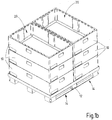
- Fig. 1a, 1b
- auf eine Palette gestapelte Stapelbehälter mit und ohne Deckel und
- Fig. 2a, 2b
- einen der Stapelbehälter gemäß
Fig. 1a ,1b in perspektivischer Ansicht von oben und von unten. - In
Fig. 1a ,1b sind mehrere Stapelbehälter 10 dargestellt, die in zwei nebeneinander auf einer Palette 12 aufgesetzten Behälterstapeln 14 angeordnet sind. Im gezeigten Ausführungsbeispiel weist jeder Behälterstapel 14 drei Stapelbehälter 10a auf, welche jeweils einstückig aus einem Partikelschaumstoff hergestellt sind. Jeder der Stapelbehälter 10a weist einen Boden 16 mit im Wesentlichen rechteckigem Grundriss sowie vier sich vom Boden 16 aus nach oben erstreckende Wände 18 auf. Die Wände 18 umschließen einen nach unten durch den Boden 16 begrenzten Aufnahmeraum 20, der nach oben offen ist und an seiner Oberseite eine Öffnung 22 aufweist. Zu jedem Stapelbehälter 10 bildet der nächstobere, auf ihn aufgesetzte Stapelbehälter 10a eine Art Deckel, indem er die Öffnung 22 vollständig verschließt. Die beiden obersten Stapelbehälter 10 werden durch einen gemeinsamen Deckel 24 verschlossen. - Aus den dem Boden 16 abgewandten Wandoberseiten 26 stehen nach oben Zähne 28 vor, zwischen denen Lücken 30 angeordnet sind. Direkt unter jedem Zahn 28, also in vertikaler Richtung gegenüber dem Zahn 28 nach unten versetzt, weist der Boden 16 an seiner Unterseite 32 jeweils eine Ausnehmung 34 auf, die komplementär zum betreffenden Zahn 28 ausgestaltet ist und in ihrer Form und Größe der Form und Größe des Zahns 28 entspricht. Insbesondere entspricht die in Längsrichtung der betreffenden Wandoberseite 26 gemessene Länge jedes Zahns 28 in etwa der Länge der zugehörigen Ausnehmung 34. Bei dem Stapelbehälter 10a gemäß dem ersten Ausführungsbeispiel sind die Zähne 28 zudem gegenüber einer durch die dem Aufnahmeraum abgewandten Außenflächen 36 der Wände 18 gebildete Außenkontur, die dem rechteckigen Grundriss des Bodens 16 entspricht, ein Stück weit nach innen in Richtung zum Aufnahmeraum 20 versetzt angeordnet. Zwischen den Zähnen 28 und der Außenkontur der Wände 18 befindet sich ein von den Wandoberseiten 26 nach oben vorstehender, rings umlaufender und an die Zähne 28 direkt angrenzender Stapelrand 38. Dementsprechend sind die Ausnehmungen 34 beim Stapelbehälter 10 zur durch den rechteckigen Grundriss des Bodens 16 definierten Außenkontur des Bodens 16 randoffen, und es erstreckt sich ein umlaufender Absatz 40 von der Außenkontur des Bodens 16 ein Stück weit nach innen, der auf dem Stapelrand 38 des nächstunteren Stapelbehälters 10 ruht. Unterseitige Flächen 42 der Ausnehmungen 34 fluchten dabei mit einer durch den Absatz 40 gebildeten rings umlaufenden unterseitigen Fläche 44. Zudem weist der Stapelrand 38 eine Fase 46 an seinen mit den Außenflächen 36 der Wände 18 fluchtenden Außenflächen 48 auf, die eine Tropfkante bildet und den Eintritt von Flüssigkeit in den Stapelbehälter 10 erschwert.
- Der Stapelbehälter 10 weist sowohl zwischen dem Boden 16 und jeder der Wände 18 als auch zwischen jeweils zwei aneinander angrenzenden Wänden 18 Fasen 52 auf, die den Winkel zwischen dem Boden 16 und der betreffenden Wand 18 bzw. den Winkel zwischen den Wänden 18 ausfüllen und eine quer zu den betreffenden Wandinnenflächen 50 bzw. quer zur Oberfläche 54 des Bodens 16 und quer zur betreffenden Wandinnenfläche 50 verlaufende, dem Aufnahmeraum 20 zugewandte Fläche bilden. Die Fasen 52 verstärken den Stapelbehälter 10 und erstrecken sich über die gesamte Wandlänge bzw. die gesamte Wandhöhe entweder bis zur Wandoberseite, wie in
Fig. 2a gezeigt, oder bis zu einer Oberseite 56 des dort angeordneten Zahns 28. - Zusammenfassend ist Folgendes festzuhalten: Die Erfindung betrifft einen einstückigen Stapelbehälter 10 mit einem Boden 16 und mit sich vom Boden 16 nach oben erstreckenden, einen nach oben offenen Aufnahmeraum 20 rings umschließenden Wänden 18, wobei aus den dem Boden 16 abgewandten Wandoberseiten 26 nach oben Zähne 28 vorstehen und wobei in einer dem Aufnahmeraum 20 abgewandten Unterseite 32 des Bodens 16 eine der Anzahl der Zähne 28 entsprechende Anzahl von Ausnehmungen 34 zur Aufnahme der Zähne 28 eines baugleichen Stapelbehälters 10 angeordnet sind und wobei die Zähne 28 und die Ausnehmungen 34 im Abstand zur Außenkontur der Wände 18 bzw. des Bodens 16 angeordnet sind und wobei um die Zähne 28 zwischen den Zähnen 28 und den dem Aufnahmeraum 20 abgewandten Außenflächen 36 der Wände 18 ein sich von den Wandoberseiten 26 nach oben erstreckender Stapelrand 38 umläuft. Erfindungsgemäß besteht der Stapelbehälter aus einem Partikelschaumstoff, insbesondere aus expandiertem Polypropylen (EPP) oder expandiertem Polyurethan (EPU).
Claims (13)
- Einstückiger Stapelbehälter (10) mit einem Boden (16) und mit sich vom Boden (16) nach oben erstreckenden, einen nach oben offenen Aufnahmeraum (20) rings umschließenden Wänden (18), wobei aus den dem Boden (16) abgewandten Wandoberseiten (26) nach oben Zähne (28) vorstehen, wobei in einer dem Aufnahmeraum (20) abgewandten Unterseite (32) des Bodens (16) eine der Anzahl der Zähne (28) entsprechende Anzahl von Ausnehmungen (34) zur Aufnahme der Zähne (28) eines baugleichen Stapelbehälters (10) angeordnet sind, wobei die Zähne (28) und die Ausnehmungen (34) im Abstand zur Außenkontur der Wände (18) bzw. des Bodens (16) angeordnet sind und wobei um die Zähne (28) zwischen den Zähnen (28) und den dem Aufnahmeraum (20) abgewandten Außenflächen (36) der Wände (18) ein sich von den Wandoberseiten (26) nach oben erstreckender Stapelrand (38) umläuft, dadurch gekennzeichnet, dass der Stapelbehälter aus einem Partikelschaumstoff, insbesondere aus expandiertem Polypropylen (EPP) oder expandiertem Polyurethan (EPU) besteht.
- Stapelbehälter (10) nach Anspruch 1, dadurch gekennzeichnet, dass dem Aufnahmeraum (20) abgewandte Außenflächen (48) des Stapelrands (38) mit den Außenflächen (36) der Wände (18) fluchten.
- Stapelbehälter (10) nach Anspruch 1 oder 2, dadurch gekennzeichnet, dass sich der Stapelrand (38) bis zur gleichen Höhe über den Wandoberseiten (26) erstreckt wie die Zähne (28).
- Stapelbehälter (10) nach einem der vorangehenden Ansprüche, dadurch gekennzeichnet, dass der Stapelrand (38) eine umlaufende Fase (46) aufweist, die eine ausgehend von seinen Außenflächen in Richtung zum Aufnahmeraum (20) ansteigende Fläche bildet.
- Stapelbehälter (10) nach einem der vorangehenden Ansprüche, dadurch gekennzeichnet, dass die Ausnehmungen (34) jeweils senkrecht unter einem der Zähne (28) angeordnet sind.
- Stapelbehälter (10) nach Anspruch 5, dadurch gekennzeichnet, dass die in Längsrichtung der Wandoberseiten (26) gemessene Länge jedes der Zähne (28) etwa der Länge der unter ihm angeordneten Ausnehmung (34) entspricht.
- Stapelbehälter (10) nach einem der Ansprüche 5 oder 6, dadurch gekennzeichnet, dass jeder der Zähne (28) in seiner Form komplementär zur unter ihm angeordneten Ausnehmung (34) ist.
- Stapelbehälter (10) nach einem der vorangehenden Ansprüche, dadurch gekennzeichnet, dass die Zähne (28) an zumindest einer der Wände (18) und vorzugsweise an jeder der Wände (18) nicht alle dieselbe Länge aufweisen.
- Stapelbehälter (10) nach Anspruch 8, dadurch gekennzeichnet, dass die Zähne (28) in der Mitte der Wände (18) eine größere Länge aufweisen als an den an die jeweils benachbarten Wände (18) angrenzenden Wandenden.
- Stapelbehälter (10) nach einem der vorangehenden Ansprüche, dadurch gekennzeichnet, dass die Zähne (28) und die Ausnehmungen (34) so dimensioniert sind, dass die Zähne (28) mit Spiel in den Ausnehmungen (34) eines baugleichen Stapelbehälters (10) aufnehmbar sind und dass das Spiel in der Mitte der Wände (18) größer ist als an den an die jeweils benachbarten Wände (18) angrenzenden Wandenden.
- Stapelbehälter (10) nach einem der vorangehenden Ansprüche, dadurch gekennzeichnet, dass die Ausnehmungen (34) zur Außenkontur des Bodens (16) randoffen sind.
- Stapelbehälter (10) nach Anspruch 11, dadurch gekennzeichnet, dass die Ausnehmungen (34) zu einem umlaufenden Absatz an der Unterseite (32) randoffen sind und eine unterseitige Fläche (42) jeder Ausnehmung (34) mit einer unterseitigen Fläche (44) des Absatzes (40) fluchtet.
- Stapelbehälter (10) nach einem der vorangehenden Ansprüche, dadurch gekennzeichnet, dass zwischen dem Boden (16) und den Wänden (18) und/oder zwischen jeweils zwei aneinander angrenzenden Wänden (18) an der dem Aufnahmeraum (20) zugewandten Seite jeweils eine Fase (52) angeordnet ist.
Priority Applications (1)
| Application Number | Priority Date | Filing Date | Title |
|---|---|---|---|
| PL18161316T PL3385187T3 (pl) | 2017-04-08 | 2018-03-12 | Pojemnik do ustawiania w stos |
Applications Claiming Priority (1)
| Application Number | Priority Date | Filing Date | Title |
|---|---|---|---|
| DE102017107598.4A DE102017107598A1 (de) | 2017-04-08 | 2017-04-08 | Stapelbehälter |
Publications (2)
| Publication Number | Publication Date |
|---|---|
| EP3385187A1 EP3385187A1 (de) | 2018-10-10 |
| EP3385187B1 true EP3385187B1 (de) | 2020-10-14 |
Family
ID=61628137
Family Applications (1)
| Application Number | Title | Priority Date | Filing Date |
|---|---|---|---|
| EP18161316.7A Active EP3385187B1 (de) | 2017-04-08 | 2018-03-12 | Stapelbehälter |
Country Status (5)
| Country | Link |
|---|---|
| EP (1) | EP3385187B1 (de) |
| DE (1) | DE102017107598A1 (de) |
| ES (1) | ES2842877T3 (de) |
| HU (1) | HUE052996T2 (de) |
| PL (1) | PL3385187T3 (de) |
Citations (1)
| Publication number | Priority date | Publication date | Assignee | Title |
|---|---|---|---|---|
| EP2860128A1 (de) * | 2013-10-02 | 2015-04-15 | Feurer Febra GmbH | Thermischer Isolierbehälter |
Family Cites Families (10)
| Publication number | Priority date | Publication date | Assignee | Title |
|---|---|---|---|---|
| US2753077A (en) * | 1952-10-20 | 1956-07-03 | Greco Albert | Alignable cans |
| US2849151A (en) * | 1955-01-27 | 1958-08-26 | American Viscose Corp | Stacking container |
| GB1116049A (en) * | 1964-12-12 | 1968-06-06 | Charles Tennant & Company Ltd | Improvements relating to containers of synthetic resinous material |
| DE1586638B1 (de) * | 1967-11-10 | 1971-01-21 | Freya Plastic Delbrouck F | Stapelbarer Flaschenkasten |
| US3481502A (en) * | 1968-06-27 | 1969-12-02 | Mitchell J Slayman | Containers with interfitted cleats |
| US5060819A (en) * | 1988-04-26 | 1991-10-29 | Rehrig-Pacific Company, Inc. | Nestable low depth tray |
| DE3822338C2 (de) * | 1988-07-01 | 1999-06-17 | Thoma Robert Rotho Kunststoff | Stapelbarer und in der Stapellage verriegelbarer Behälter |
| DE29904563U1 (de) * | 1999-03-12 | 1999-06-10 | Ruch Novaplast GmbH + Co. KG., 77704 Oberkirch | Stapelbare Verpackung |
| DE20104892U1 (de) * | 2001-03-21 | 2001-09-27 | neoLab Migge Laborbedarf-Vertriebs GmbH, 69123 Heidelberg | neoStapelRack, Stapelsystem zur Aufnahme von Boxen für den labortechnischen Bedarf |
| US20070144931A1 (en) * | 2005-12-22 | 2007-06-28 | Drader Manufacturing Industries Ltd. | Two stacking position square container |
-
2017
- 2017-04-08 DE DE102017107598.4A patent/DE102017107598A1/de active Pending
-
2018
- 2018-03-12 HU HUE18161316A patent/HUE052996T2/hu unknown
- 2018-03-12 ES ES18161316T patent/ES2842877T3/es active Active
- 2018-03-12 PL PL18161316T patent/PL3385187T3/pl unknown
- 2018-03-12 EP EP18161316.7A patent/EP3385187B1/de active Active
Patent Citations (1)
| Publication number | Priority date | Publication date | Assignee | Title |
|---|---|---|---|---|
| EP2860128A1 (de) * | 2013-10-02 | 2015-04-15 | Feurer Febra GmbH | Thermischer Isolierbehälter |
Also Published As
| Publication number | Publication date |
|---|---|
| PL3385187T3 (pl) | 2021-04-19 |
| EP3385187A1 (de) | 2018-10-10 |
| ES2842877T3 (es) | 2021-07-15 |
| HUE052996T2 (hu) | 2021-06-28 |
| DE102017107598A1 (de) | 2018-10-11 |
Similar Documents
| Publication | Publication Date | Title |
|---|---|---|
| EP1730042B1 (de) | Kombination von drehstapelbehältern unterschiedlicher grösse | |
| EP2582585B1 (de) | Transportbehälter | |
| DE4117159A1 (de) | Transport- und/oder lagerbehaelter | |
| EP2552794B1 (de) | Formteil zur aufnahme und fixierung von im umriss rechteckigen lagerbehältern | |
| EP2727854A1 (de) | Vorrichtung zur Ausrichtung eines Stapels von Behältern | |
| DE2254724A1 (de) | Ineinandergreifendes paletten- und behaeltersystem | |
| EP3290347B1 (de) | Vorrichtung zum transport von stückgütern | |
| EP0436783A1 (de) | Palette mit einer aufgelegten Platte zur Verhinderung des Verrutschens des aus Transportkästen bestehenden Ladegutes und aus diesen Teilen bestehender Stapel | |
| WO2016192700A1 (de) | Pipettenspitzenverpackung | |
| DE19641686C2 (de) | Stapelbarer Behälter, insbesondere Lager- und Transportbehälter sowie Behältersystem | |
| DE102019125071B3 (de) | Transportsystem für Stückgüter | |
| DE19628373A1 (de) | Transportbehälter aus Kunststoff, der nach dem Drehstapelprinzip stapelbar ist | |
| DE29513797U1 (de) | Stapelbare Transportverpackung für Große Hausgeräte | |
| EP3385187A1 (de) | Stapelbehälter | |
| EP3543158B1 (de) | Transportbehälter | |
| EP4217277A1 (de) | Transportbehälter | |
| DE3934800A1 (de) | Stapeltransportkasten aus metallischem schichtmaterial | |
| DE4000724C2 (de) | Vorrichtung zur Verhinderung des Verrutschens von Transportkästen auf Paletten und aus diesen Paletten und Transportkästen bestehender Stapel | |
| EP4192751B1 (de) | Kunststoffbehälter | |
| DE102010019620B4 (de) | Anordnung mit einer Palette, mit einer von der Palette getragenen Ladung und mit einer Ladeabschlussplatte | |
| EP4612061A1 (de) | Transportpalette | |
| DE9413518U1 (de) | Zusammenlegbarer Behälter | |
| DE19646608A1 (de) | Mehrweg-Transportpackung für technische Geräte | |
| DE102005021170A1 (de) | Transport- und Lagerbehälter | |
| WO2020035457A1 (de) | Palette aus kunststoff mit einem oberdeck, einem unterteil und verstärkungsgliedern |
Legal Events
| Date | Code | Title | Description |
|---|---|---|---|
| PUAI | Public reference made under article 153(3) epc to a published international application that has entered the european phase |
Free format text: ORIGINAL CODE: 0009012 |
|
| STAA | Information on the status of an ep patent application or granted ep patent |
Free format text: STATUS: THE APPLICATION HAS BEEN PUBLISHED |
|
| AK | Designated contracting states |
Kind code of ref document: A1 Designated state(s): AL AT BE BG CH CY CZ DE DK EE ES FI FR GB GR HR HU IE IS IT LI LT LU LV MC MK MT NL NO PL PT RO RS SE SI SK SM TR |
|
| AX | Request for extension of the european patent |
Extension state: BA ME |
|
| STAA | Information on the status of an ep patent application or granted ep patent |
Free format text: STATUS: REQUEST FOR EXAMINATION WAS MADE |
|
| 17P | Request for examination filed |
Effective date: 20190401 |
|
| RBV | Designated contracting states (corrected) |
Designated state(s): AL AT BE BG CH CY CZ DE DK EE ES FI FR GB GR HR HU IE IS IT LI LT LU LV MC MK MT NL NO PL PT RO RS SE SI SK SM TR |
|
| STAA | Information on the status of an ep patent application or granted ep patent |
Free format text: STATUS: EXAMINATION IS IN PROGRESS |
|
| 17Q | First examination report despatched |
Effective date: 20191119 |
|
| GRAP | Despatch of communication of intention to grant a patent |
Free format text: ORIGINAL CODE: EPIDOSNIGR1 |
|
| STAA | Information on the status of an ep patent application or granted ep patent |
Free format text: STATUS: GRANT OF PATENT IS INTENDED |
|
| INTG | Intention to grant announced |
Effective date: 20200624 |
|
| GRAS | Grant fee paid |
Free format text: ORIGINAL CODE: EPIDOSNIGR3 |
|
| GRAA | (expected) grant |
Free format text: ORIGINAL CODE: 0009210 |
|
| STAA | Information on the status of an ep patent application or granted ep patent |
Free format text: STATUS: THE PATENT HAS BEEN GRANTED |
|
| AK | Designated contracting states |
Kind code of ref document: B1 Designated state(s): AL AT BE BG CH CY CZ DE DK EE ES FI FR GB GR HR HU IE IS IT LI LT LU LV MC MK MT NL NO PL PT RO RS SE SI SK SM TR |
|
| REG | Reference to a national code |
Ref country code: GB Ref legal event code: FG4D Free format text: NOT ENGLISH |
|
| REG | Reference to a national code |
Ref country code: AT Ref legal event code: REF Ref document number: 1323347 Country of ref document: AT Kind code of ref document: T Effective date: 20201015 Ref country code: CH Ref legal event code: EP |
|
| REG | Reference to a national code |
Ref country code: DE Ref legal event code: R096 Ref document number: 502018002705 Country of ref document: DE |
|
| REG | Reference to a national code |
Ref country code: IE Ref legal event code: FG4D Free format text: LANGUAGE OF EP DOCUMENT: GERMAN |
|
| REG | Reference to a national code |
Ref country code: NL Ref legal event code: FP |
|
| REG | Reference to a national code |
Ref country code: SK Ref legal event code: T3 Ref document number: E 36469 Country of ref document: SK |
|
| PG25 | Lapsed in a contracting state [announced via postgrant information from national office to epo] |
Ref country code: FI Free format text: LAPSE BECAUSE OF FAILURE TO SUBMIT A TRANSLATION OF THE DESCRIPTION OR TO PAY THE FEE WITHIN THE PRESCRIBED TIME-LIMIT Effective date: 20201014 Ref country code: RS Free format text: LAPSE BECAUSE OF FAILURE TO SUBMIT A TRANSLATION OF THE DESCRIPTION OR TO PAY THE FEE WITHIN THE PRESCRIBED TIME-LIMIT Effective date: 20201014 Ref country code: PT Free format text: LAPSE BECAUSE OF FAILURE TO SUBMIT A TRANSLATION OF THE DESCRIPTION OR TO PAY THE FEE WITHIN THE PRESCRIBED TIME-LIMIT Effective date: 20210215 Ref country code: NO Free format text: LAPSE BECAUSE OF FAILURE TO SUBMIT A TRANSLATION OF THE DESCRIPTION OR TO PAY THE FEE WITHIN THE PRESCRIBED TIME-LIMIT Effective date: 20210114 Ref country code: GR Free format text: LAPSE BECAUSE OF FAILURE TO SUBMIT A TRANSLATION OF THE DESCRIPTION OR TO PAY THE FEE WITHIN THE PRESCRIBED TIME-LIMIT Effective date: 20210115 |
|
| REG | Reference to a national code |
Ref country code: LT Ref legal event code: MG4D |
|
| PG25 | Lapsed in a contracting state [announced via postgrant information from national office to epo] |
Ref country code: BG Free format text: LAPSE BECAUSE OF FAILURE TO SUBMIT A TRANSLATION OF THE DESCRIPTION OR TO PAY THE FEE WITHIN THE PRESCRIBED TIME-LIMIT Effective date: 20210114 Ref country code: LV Free format text: LAPSE BECAUSE OF FAILURE TO SUBMIT A TRANSLATION OF THE DESCRIPTION OR TO PAY THE FEE WITHIN THE PRESCRIBED TIME-LIMIT Effective date: 20201014 Ref country code: IS Free format text: LAPSE BECAUSE OF FAILURE TO SUBMIT A TRANSLATION OF THE DESCRIPTION OR TO PAY THE FEE WITHIN THE PRESCRIBED TIME-LIMIT Effective date: 20210214 Ref country code: SE Free format text: LAPSE BECAUSE OF FAILURE TO SUBMIT A TRANSLATION OF THE DESCRIPTION OR TO PAY THE FEE WITHIN THE PRESCRIBED TIME-LIMIT Effective date: 20201014 |
|
| REG | Reference to a national code |
Ref country code: HU Ref legal event code: AG4A Ref document number: E052996 Country of ref document: HU |
|
| PG25 | Lapsed in a contracting state [announced via postgrant information from national office to epo] |
Ref country code: HR Free format text: LAPSE BECAUSE OF FAILURE TO SUBMIT A TRANSLATION OF THE DESCRIPTION OR TO PAY THE FEE WITHIN THE PRESCRIBED TIME-LIMIT Effective date: 20201014 |
|
| REG | Reference to a national code |
Ref country code: DE Ref legal event code: R097 Ref document number: 502018002705 Country of ref document: DE Ref country code: ES Ref legal event code: FG2A Ref document number: 2842877 Country of ref document: ES Kind code of ref document: T3 Effective date: 20210715 |
|
| PG25 | Lapsed in a contracting state [announced via postgrant information from national office to epo] |
Ref country code: RO Free format text: LAPSE BECAUSE OF FAILURE TO SUBMIT A TRANSLATION OF THE DESCRIPTION OR TO PAY THE FEE WITHIN THE PRESCRIBED TIME-LIMIT Effective date: 20201014 Ref country code: LT Free format text: LAPSE BECAUSE OF FAILURE TO SUBMIT A TRANSLATION OF THE DESCRIPTION OR TO PAY THE FEE WITHIN THE PRESCRIBED TIME-LIMIT Effective date: 20201014 Ref country code: EE Free format text: LAPSE BECAUSE OF FAILURE TO SUBMIT A TRANSLATION OF THE DESCRIPTION OR TO PAY THE FEE WITHIN THE PRESCRIBED TIME-LIMIT Effective date: 20201014 Ref country code: SM Free format text: LAPSE BECAUSE OF FAILURE TO SUBMIT A TRANSLATION OF THE DESCRIPTION OR TO PAY THE FEE WITHIN THE PRESCRIBED TIME-LIMIT Effective date: 20201014 |
|
| PLBE | No opposition filed within time limit |
Free format text: ORIGINAL CODE: 0009261 |
|
| STAA | Information on the status of an ep patent application or granted ep patent |
Free format text: STATUS: NO OPPOSITION FILED WITHIN TIME LIMIT |
|
| PG25 | Lapsed in a contracting state [announced via postgrant information from national office to epo] |
Ref country code: DK Free format text: LAPSE BECAUSE OF FAILURE TO SUBMIT A TRANSLATION OF THE DESCRIPTION OR TO PAY THE FEE WITHIN THE PRESCRIBED TIME-LIMIT Effective date: 20201014 |
|
| 26N | No opposition filed |
Effective date: 20210715 |
|
| PG25 | Lapsed in a contracting state [announced via postgrant information from national office to epo] |
Ref country code: AL Free format text: LAPSE BECAUSE OF FAILURE TO SUBMIT A TRANSLATION OF THE DESCRIPTION OR TO PAY THE FEE WITHIN THE PRESCRIBED TIME-LIMIT Effective date: 20201014 Ref country code: MC Free format text: LAPSE BECAUSE OF FAILURE TO SUBMIT A TRANSLATION OF THE DESCRIPTION OR TO PAY THE FEE WITHIN THE PRESCRIBED TIME-LIMIT Effective date: 20201014 |
|
| REG | Reference to a national code |
Ref country code: CH Ref legal event code: PL |
|
| PG25 | Lapsed in a contracting state [announced via postgrant information from national office to epo] |
Ref country code: SI Free format text: LAPSE BECAUSE OF FAILURE TO SUBMIT A TRANSLATION OF THE DESCRIPTION OR TO PAY THE FEE WITHIN THE PRESCRIBED TIME-LIMIT Effective date: 20201014 |
|
| REG | Reference to a national code |
Ref country code: BE Ref legal event code: MM Effective date: 20210331 |
|
| PG25 | Lapsed in a contracting state [announced via postgrant information from national office to epo] |
Ref country code: LU Free format text: LAPSE BECAUSE OF NON-PAYMENT OF DUE FEES Effective date: 20210312 Ref country code: IE Free format text: LAPSE BECAUSE OF NON-PAYMENT OF DUE FEES Effective date: 20210312 Ref country code: LI Free format text: LAPSE BECAUSE OF NON-PAYMENT OF DUE FEES Effective date: 20210331 Ref country code: CH Free format text: LAPSE BECAUSE OF NON-PAYMENT OF DUE FEES Effective date: 20210331 |
|
| PG25 | Lapsed in a contracting state [announced via postgrant information from national office to epo] |
Ref country code: IS Free format text: LAPSE BECAUSE OF FAILURE TO SUBMIT A TRANSLATION OF THE DESCRIPTION OR TO PAY THE FEE WITHIN THE PRESCRIBED TIME-LIMIT Effective date: 20210214 |
|
| PG25 | Lapsed in a contracting state [announced via postgrant information from national office to epo] |
Ref country code: BE Free format text: LAPSE BECAUSE OF NON-PAYMENT OF DUE FEES Effective date: 20210331 |
|
| PG25 | Lapsed in a contracting state [announced via postgrant information from national office to epo] |
Ref country code: CY Free format text: LAPSE BECAUSE OF FAILURE TO SUBMIT A TRANSLATION OF THE DESCRIPTION OR TO PAY THE FEE WITHIN THE PRESCRIBED TIME-LIMIT Effective date: 20201014 |
|
| PG25 | Lapsed in a contracting state [announced via postgrant information from national office to epo] |
Ref country code: MK Free format text: LAPSE BECAUSE OF FAILURE TO SUBMIT A TRANSLATION OF THE DESCRIPTION OR TO PAY THE FEE WITHIN THE PRESCRIBED TIME-LIMIT Effective date: 20201014 |
|
| REG | Reference to a national code |
Ref country code: AT Ref legal event code: MM01 Ref document number: 1323347 Country of ref document: AT Kind code of ref document: T Effective date: 20230312 |
|
| PG25 | Lapsed in a contracting state [announced via postgrant information from national office to epo] |
Ref country code: TR Free format text: LAPSE BECAUSE OF FAILURE TO SUBMIT A TRANSLATION OF THE DESCRIPTION OR TO PAY THE FEE WITHIN THE PRESCRIBED TIME-LIMIT Effective date: 20201014 |
|
| PG25 | Lapsed in a contracting state [announced via postgrant information from national office to epo] |
Ref country code: AT Free format text: LAPSE BECAUSE OF NON-PAYMENT OF DUE FEES Effective date: 20230312 |
|
| PG25 | Lapsed in a contracting state [announced via postgrant information from national office to epo] |
Ref country code: AT Free format text: LAPSE BECAUSE OF NON-PAYMENT OF DUE FEES Effective date: 20230312 |
|
| PG25 | Lapsed in a contracting state [announced via postgrant information from national office to epo] |
Ref country code: MT Free format text: LAPSE BECAUSE OF FAILURE TO SUBMIT A TRANSLATION OF THE DESCRIPTION OR TO PAY THE FEE WITHIN THE PRESCRIBED TIME-LIMIT Effective date: 20201014 |
|
| PGFP | Annual fee paid to national office [announced via postgrant information from national office to epo] |
Ref country code: ES Payment date: 20250429 Year of fee payment: 8 |
|
| PGFP | Annual fee paid to national office [announced via postgrant information from national office to epo] |
Ref country code: GB Payment date: 20260324 Year of fee payment: 9 |
|
| PGFP | Annual fee paid to national office [announced via postgrant information from national office to epo] |
Ref country code: DE Payment date: 20260226 Year of fee payment: 9 |
|
| PGFP | Annual fee paid to national office [announced via postgrant information from national office to epo] |
Ref country code: AT Payment date: 20260410 Year of fee payment: 5 |
|
| PGFP | Annual fee paid to national office [announced via postgrant information from national office to epo] |
Ref country code: IT Payment date: 20260324 Year of fee payment: 9 |
|
| PGFP | Annual fee paid to national office [announced via postgrant information from national office to epo] |
Ref country code: HU Payment date: 20260323 Year of fee payment: 9 Ref country code: NL Payment date: 20260319 Year of fee payment: 9 |
|
| PGFP | Annual fee paid to national office [announced via postgrant information from national office to epo] |
Ref country code: FR Payment date: 20260320 Year of fee payment: 9 |
|
| PGFP | Annual fee paid to national office [announced via postgrant information from national office to epo] |
Ref country code: CZ Payment date: 20260310 Year of fee payment: 9 |
|
| PGFP | Annual fee paid to national office [announced via postgrant information from national office to epo] |
Ref country code: PL Payment date: 20260306 Year of fee payment: 9 |
|
| PGFP | Annual fee paid to national office [announced via postgrant information from national office to epo] |
Ref country code: SK Payment date: 20260310 Year of fee payment: 9 |