EP3385209B1 - Machine de levage et ascenseur - Google Patents
Machine de levage et ascenseur Download PDFInfo
- Publication number
- EP3385209B1 EP3385209B1 EP18165780.0A EP18165780A EP3385209B1 EP 3385209 B1 EP3385209 B1 EP 3385209B1 EP 18165780 A EP18165780 A EP 18165780A EP 3385209 B1 EP3385209 B1 EP 3385209B1
- Authority
- EP
- European Patent Office
- Prior art keywords
- hoist machine
- support base
- housing
- main shaft
- elevator
- Prior art date
- Legal status (The legal status is an assumption and is not a legal conclusion. Google has not performed a legal analysis and makes no representation as to the accuracy of the status listed.)
- Active
Links
Images

Classifications
-
- F—MECHANICAL ENGINEERING; LIGHTING; HEATING; WEAPONS; BLASTING
- F16—ENGINEERING ELEMENTS AND UNITS; GENERAL MEASURES FOR PRODUCING AND MAINTAINING EFFECTIVE FUNCTIONING OF MACHINES OR INSTALLATIONS; THERMAL INSULATION IN GENERAL
- F16C—SHAFTS; FLEXIBLE SHAFTS; ELEMENTS OR CRANKSHAFT MECHANISMS; ROTARY BODIES OTHER THAN GEARING ELEMENTS; BEARINGS
- F16C35/00—Rigid support of bearing units; Housings, e.g. caps, covers
- F16C35/04—Rigid support of bearing units; Housings, e.g. caps, covers in the case of ball or roller bearings
- F16C35/042—Housings for rolling element bearings for rotary movement
- F16C35/045—Housings for rolling element bearings for rotary movement with a radial flange to mount the housing
-
- B—PERFORMING OPERATIONS; TRANSPORTING
- B66—HOISTING; LIFTING; HAULING
- B66B—ELEVATORS; ESCALATORS OR MOVING WALKWAYS
- B66B11/00—Main component parts of lifts in, or associated with, buildings or other structures
- B66B11/04—Driving gear ; Details thereof, e.g. seals
- B66B11/043—Driving gear ; Details thereof, e.g. seals actuated by rotating motor; Details, e.g. ventilation
- B66B11/0438—Driving gear ; Details thereof, e.g. seals actuated by rotating motor; Details, e.g. ventilation with a gearless driving, e.g. integrated sheave, drum or winch in the stator or rotor of the cage motor
-
- B—PERFORMING OPERATIONS; TRANSPORTING
- B66—HOISTING; LIFTING; HAULING
- B66B—ELEVATORS; ESCALATORS OR MOVING WALKWAYS
- B66B9/00—Kinds or types of lifts in, or associated with, buildings or other structures
-
- F—MECHANICAL ENGINEERING; LIGHTING; HEATING; WEAPONS; BLASTING
- F16—ENGINEERING ELEMENTS AND UNITS; GENERAL MEASURES FOR PRODUCING AND MAINTAINING EFFECTIVE FUNCTIONING OF MACHINES OR INSTALLATIONS; THERMAL INSULATION IN GENERAL
- F16C—SHAFTS; FLEXIBLE SHAFTS; ELEMENTS OR CRANKSHAFT MECHANISMS; ROTARY BODIES OTHER THAN GEARING ELEMENTS; BEARINGS
- F16C2326/00—Articles relating to transporting
-
- F—MECHANICAL ENGINEERING; LIGHTING; HEATING; WEAPONS; BLASTING
- F16—ENGINEERING ELEMENTS AND UNITS; GENERAL MEASURES FOR PRODUCING AND MAINTAINING EFFECTIVE FUNCTIONING OF MACHINES OR INSTALLATIONS; THERMAL INSULATION IN GENERAL
- F16C—SHAFTS; FLEXIBLE SHAFTS; ELEMENTS OR CRANKSHAFT MECHANISMS; ROTARY BODIES OTHER THAN GEARING ELEMENTS; BEARINGS
- F16C35/00—Rigid support of bearing units; Housings, e.g. caps, covers
- F16C35/04—Rigid support of bearing units; Housings, e.g. caps, covers in the case of ball or roller bearings
- F16C35/06—Mounting or dismounting of ball or roller bearings; Fixing them onto shaft or in housing
- F16C35/07—Fixing them on the shaft or housing with interposition of an element
- F16C35/077—Fixing them on the shaft or housing with interposition of an element between housing and outer race ring
Definitions
- the present invention relates to a hoist machine and an elevator.
- Patent Literature 1 discloses a hoist machine.
- the Patent Literature 1 explains the hoist machine as follows. "A hoist machine includes a housing constituted by a pair of support walls, and a top board. The support walls face with each other at intervals while standing from a floor board. Each support wall includes a hollow cylindrical boss. The bosses are coaxially arranged in a horizontal direction. A rotary shaft is spanned over the bosses. The rotary shaft is horizontally disposed so as to be orthogonal to a hoistway. One end of the rotary shaft is rotatably supported with one of the bosses via a first roll bearing. The other end of the rotary shaft is rotatably supported with the other boss via a second roll bearing.”
- DE 10 2005 047404 A1 proposes a lifting transmission including a rotor element on a fixed axis extending from a stator element and an adjustment element.
- WO 2011/023559 A1 proposes a bearing arrangement comprising a bearing support, wherein the bearing support comprises at least one receptacle for a bearing.
- EP 1 886 962 A1 proposes a traction machine for elevators.
- EP 1 705 148 A1 proposes an elevator hoisting machine having a rotary portion rotatably supported by a base member.
- a bearing housing for supporting the end of the rotary shaft of the hoist machine at the sheave device side (the side opposite the casing) is disposed in the support wall. Accordingly, the rotary shaft extends to the end of the support wall at the sheave device side.
- the hoist machine is brought and installed in the existing building while having the support section for the rotary shaft kept attached.
- the dimension of the hoist machine in the axial direction of the rotary shaft upon carry-in and installation corresponds to the length from the outer end of the casing to the outer end of the support section.
- a hoist machine as set out in claim 1.
- an elevator as set out in claim 5.
- the present invention is capable of reducing the axial dimension of the hoist machine by removing at least a part of the support section.
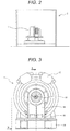
- Fig. 1 is a view schematically illustrating an elevator according to an embodiment of the present invention.
- Fig. 2 is a side view of a hoist machine disposed in a machine chamber.
- An elevator 2 using a hoist machine 1 is configured to allow a car 4 and a counter weight 5 which are linked with a main rope 3 to be liftable in a hoistway.
- the hoist machine 1 is disposed between the car 4 and the counter weight 5 via the main rope 3.
- Fig. 3 is a front view of the hoist machine as shown in Fig. 2 .
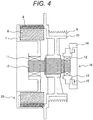
- Fig. 4 is a horizontal sectional view of the hoist machine as shown in Fig. 3 .
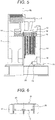
- Fig. 5 is a sectional view of the hoist machine taken along line A-O-B of Fig. 3 .
- Fig. 6 is a sectional view of the hoist machine taken along line C-C of Fig. 3 .
- the hoist machine 1 includes a casing 7 in which a stator 6 constituting a motor 23 is stored, a rotor 8 constituting the motor 23 while being arranged to face the stator 6, a frame 22 to which the rotor 8 is attached, a sheave device 9 attached to the frame 22, and a brake 17 brought into contact with the frame 22 for braking rotating motions of the sheave device 9.
- the main rope 3 is wound around the sheave device 9 which rotates together with the rotor 8.
- the hoist machine 1 placed on a machine base 19 is configured to drive the car 4 for moving up and down via the main rope 3.
- the frame 22 rotates together with a main shaft 10 having one end at the casing side in the axial direction attached to the casing 7 via a casing side bearing 11, and the other end at the sheave device side supported with a support section 16.
- the support section 16 will be explained.
- the support section 16 includes a support base side bearing 12, a housing 13, a support base 14, and a bolt 15.
- the support base side bearing 12 is attached to the other end of the main shaft 10, and disposed inside the housing 13.
- the housing 13 as a part of the support section 16 is disposed closer to the casing than the support base 14 in the axial direction of the main shaft 10.
- the housing 13 as a part of the support section 16 is configured to be disposed in the inner space of the sheave device 9.
- the inner space refers to the space defined by the main shaft 10 and the surface of the frame 22, which faces the main shaft 10.
- At least a part of the housing 13 is at a position interposed between the main shaft 10 and the frame 22.
- the housing 13 and the support base 14 are assembled with the bolt 15 so as to allow the casing side bearing 11 and the support base side bearing 12 to bear the suspension load of the car 4, the counter weight 5 and the like, which is applied to the sheave device 9 via the main rope 3.
- the casing 7 bears the suspension load via the casing side bearing 11.
- the support base 14 is fixed (connected) to the housing 13 with the bolt 15.
- the frictional force is generated between the housing 13 and the support base 14 under the axial force as a result of fastening the bolt 15 for bearing the suspension load.
- the hoist machine according to the embodiment of the present invention is configured to have the housing 13 closer to the casing than the support base 14. Further, it is sufficient that the end of the main shaft 10 at sheave device side is located at a position which the support base side bearing 12 is able to support the end of the main shaft 10. It is, therefore, possible to shorten the length of the extended end of the main shaft 10 at sheave device side by the amount corresponding to the distance reduced as a result of the positional difference between the housing 13 and the support base 14. The above-described reduction hardly hinders the support base side bearing 12 from supporting the end of the main shaft 10.
- Removal of the support section 16, or the support base 14 as a part of the support section 16 makes it possible to make both the weight and the axial dimension of the hoist machine 1 smaller than the case before removal.
- the hoist machine In the case of carry-in and installation of the hoist machine 1 in the disassembled state by removing at least a part of the support section 16, the hoist machine has to be reassembled in the machine chamber of the building.
- the hoist machine is installed in the existing building in such cases as renewal or failure of the elevator. In either case, it is preferable to make the days for deactivating the elevator fewer. Therefore, the hoist machine has to be configured to be easily reassembled.
- the bearing housing of the heavily weighed support base 14 has to be directly fitted with the support base side bearing 12 as the precision component, resulting in deteriorated workability.
- the housing 13 is separable from the support base 14. They can be assembled and fastened with the bolt 15.
- the present invention ensures to reduce the axial dimension of the hoist machine expected to be brought and installed in the disassembled state, and to facilitate the assembly work in the building.
- At least a part of the housing 13 which partially constitutes the support section 16 is disposed in the inner space of the sheave device 9. This makes it possible to shorten the length of the extended end of the main shaft 10 at the sheave device side compared with the structure having the housing 13 disposed outside the inner space of the sheave device 9.
- the hoist machine 1 further includes an oil reservoir 21 on a leg 24 of the support base 14, extending toward the casing.
- the oil reservoir 21 is constituted by a recess 25 formed in the leg 24, and a lid 20 that covers the end of the recess 25 at the casing side.
- the lid 20 is fixed to the support base 14 with the bolt.
- the support base 14 has an opening 18 located at the level higher than the oil reservoir 21.
- the above described structure allows the oil reservoir 21 to catch the oil leaked through the housing 13 closer to the casing than the support base 14.
- the opening 18 allows the operator to inspect the oil leakage from the outside.
- the structure according to the embodiment of the present invention has the opening 18 formed in the support base 14 so that the oil reservoir 21 is cleaned from the opening 18.
- the present invention is not restricted to the embodiment as described above, and allows various modifications.
- the structure having the rotatable main shaft 10 has been described as the example.
- the fixed shaft as the main shaft.
- the support section 16 by assembling the component formed by integrating the housing 13 and the support base 14, and the support base side bearing attached to the inside of the housing of the integrated component.
- the axial dimension of the hoist machine may be reduced in the state where the support base is removed.
Landscapes
- Engineering & Computer Science (AREA)
- Mechanical Engineering (AREA)
- Structural Engineering (AREA)
- Civil Engineering (AREA)
- General Engineering & Computer Science (AREA)
- Automation & Control Theory (AREA)
- Cage And Drive Apparatuses For Elevators (AREA)
- Lift-Guide Devices, And Elevator Ropes And Cables (AREA)
Claims (5)
- Machine de levage d'ascenseur (1) comprenant :un dispositif à poulie (9) ;un cadre (22) auquel le dispositif à poulie (9) est fixé ;un arbre principal (10) pour supporter le cadre (22) ;un carter (7) pour supporter une extrémité de l'arbre principal (10) ; etune section de support (16) pour supporter l'autre extrémité de l'arbre principal (10),dans lequel la section de support (16) comprend un palier (12) fixé à l'arbre principal (10) au niveau d'un côté de l'autre extrémité, un logement (13) ayant le palier (12) disposé dans un espace intérieur, et une base de support (14) auquel est fixé le logement (13),caractérisé en ce que :le logement (13) est disposé plus près du carter (7) que de la base de support (14) dans une direction axiale de l'arbre principal (10) ; etdans une vue en coupe latérale de la machine de levage d'ascenseur, au moins une partie du logement (13) est disposée dans une position interposée entre l'arbre principal (10) et le cadre (22).
- Machine de levage d'ascenseur (1) selon la revendication 1, comprenant en outre un boulon (15) pour fixer le logement (13) et la base de support (14) qui sont séparés l'un de l'autre.
- Machine de levage d'ascenseur (1) selon la revendication 1 ou la revendication 2, dans laquelle :la base de support (14) est munie d'un réservoir d'huile (21) ; etle réservoir d'huile (21) est configuré avec un évidement (25) formé dans une jambe (24) de la base de support (14), s'étendant vers le carter (7), et un couvercle (20) fixé à une extrémité de la jambe (24).
- Machine de levage d'ascenseur (1) selon la revendication 3, dans laquelle la base de support (14) comprend une ouverture (18) à un niveau supérieur au réservoir d'huile (21).
- Ascenseur (2) comprenant :une cabine (4) configurée pour se déplacer verticalement dans une cage ;un contrepoids (5) configuré pour se déplacer verticalement dans la cage ;un câble principal (3) pour relier la cabine (4) et le contrepoids (5) ; etune machine de levage (1) pour déplacer la cabine (4) et le contrepoids (5) verticalement en hissant le câble principal (3), caractérisée en ce quela machine de levage selon l'une quelconque des revendications 1 à 4 est utilisée comme machine de levage (1).
Applications Claiming Priority (1)
| Application Number | Priority Date | Filing Date | Title |
|---|---|---|---|
| JP2017076402A JP6742269B2 (ja) | 2017-04-07 | 2017-04-07 | 巻上機およびエレベーター |
Publications (2)
| Publication Number | Publication Date |
|---|---|
| EP3385209A1 EP3385209A1 (fr) | 2018-10-10 |
| EP3385209B1 true EP3385209B1 (fr) | 2020-01-22 |
Family
ID=61906709
Family Applications (1)
| Application Number | Title | Priority Date | Filing Date |
|---|---|---|---|
| EP18165780.0A Active EP3385209B1 (fr) | 2017-04-07 | 2018-04-04 | Machine de levage et ascenseur |
Country Status (3)
| Country | Link |
|---|---|
| EP (1) | EP3385209B1 (fr) |
| JP (1) | JP6742269B2 (fr) |
| CN (1) | CN108689283B (fr) |
Families Citing this family (4)
| Publication number | Priority date | Publication date | Assignee | Title |
|---|---|---|---|---|
| US20220025525A1 (en) | 2018-09-21 | 2022-01-27 | Asahi Kasei Kabushiki Kaisha | Jig for laminate production, method for laminate production, package, laminate, electrolyzer, and method for producing electrolyzer |
| CN109250614A (zh) * | 2018-11-27 | 2019-01-22 | 中实洛阳重型机械有限公司 | 一种新型单绳摩擦式矿井提升机 |
| EP3659955A1 (fr) * | 2018-11-30 | 2020-06-03 | Inventio AG | Machine synchrone direct à aimant permanent pour un ascenseur |
| WO2020255285A1 (fr) * | 2019-06-19 | 2020-12-24 | 株式会社日立製作所 | Palan, dispositif d'ascenseur l'utilisant et dispositif de poulie |
Family Cites Families (14)
| Publication number | Priority date | Publication date | Assignee | Title |
|---|---|---|---|---|
| JP2005053672A (ja) * | 2003-08-06 | 2005-03-03 | Mitsubishi Electric Corp | エレベータ用巻上機のブレーキ装置 |
| WO2005068338A1 (fr) * | 2004-01-15 | 2005-07-28 | Mitsubishi Denki Kabushiki Kaisha | Treuil d'ascenseur |
| EP1719731A4 (fr) * | 2004-02-25 | 2009-11-11 | Mitsubishi Electric Corp | Treuil d'élévateur |
| JP4636362B2 (ja) * | 2004-08-23 | 2011-02-23 | 株式会社安川電機 | 電動機 |
| JP4365345B2 (ja) * | 2004-10-20 | 2009-11-18 | 三菱電機株式会社 | 巻上機及びその据付方法 |
| JP2006219274A (ja) * | 2005-02-14 | 2006-08-24 | Mitsubishi Electric Corp | エレベータ用巻上機及びエレベータ用巻上機の軸受交換方法 |
| KR100932587B1 (ko) * | 2005-05-30 | 2009-12-17 | 미쓰비시덴키 가부시키가이샤 | 엘리베이터용 권상기 |
| JP5229860B2 (ja) | 2007-08-10 | 2013-07-03 | 東芝エレベータ株式会社 | エレベータ用巻上機 |
| JP4550120B2 (ja) * | 2008-01-28 | 2010-09-22 | 株式会社日立製作所 | エレベータ用巻上機 |
| JP2010100373A (ja) * | 2008-10-22 | 2010-05-06 | Mitsubishi Electric Corp | エレベータ巻上機及びエレベータ装置 |
| JP5238473B2 (ja) * | 2008-12-16 | 2013-07-17 | 株式会社日立産機システム | エレベータ用巻上機及びその駆動モータ |
| US20120207416A1 (en) * | 2009-08-24 | 2012-08-16 | Berthold Beyfuss | Bearing assembly |
| CN201574018U (zh) * | 2010-01-08 | 2010-09-08 | 浙江玛拓驱动设备有限公司 | 一种无座永磁同步曳引机 |
| WO2015132850A1 (fr) * | 2014-03-03 | 2015-09-11 | 三菱電機株式会社 | Treuil d'ascenseur |
-
2017
- 2017-04-07 JP JP2017076402A patent/JP6742269B2/ja active Active
-
2018
- 2018-04-03 CN CN201810288242.3A patent/CN108689283B/zh active Active
- 2018-04-04 EP EP18165780.0A patent/EP3385209B1/fr active Active
Non-Patent Citations (1)
| Title |
|---|
| None * |
Also Published As
| Publication number | Publication date |
|---|---|
| JP2018177415A (ja) | 2018-11-15 |
| CN108689283B (zh) | 2020-07-14 |
| JP6742269B2 (ja) | 2020-08-19 |
| EP3385209A1 (fr) | 2018-10-10 |
| CN108689283A (zh) | 2018-10-23 |
Similar Documents
| Publication | Publication Date | Title |
|---|---|---|
| EP3385209B1 (fr) | Machine de levage et ascenseur | |
| CN101423167B (zh) | 电梯以及该电梯使用的卷扬机和电动机 | |
| EP1630120A1 (fr) | Treuil et moteur d'ascenseur | |
| KR100740390B1 (ko) | 권상기 및 권상기 본체의 제조 방법 | |
| KR101332584B1 (ko) | 베어링 카트리지 및 엘리베이터 머신 조립체 | |
| JP5798029B2 (ja) | エレベータ用巻上機 | |
| KR20070065318A (ko) | 엘리베이터용 권상기 및 엘리베이터용 권상기의 베어링교환방법 | |
| JP5951038B2 (ja) | エレベータの吊り車装置 | |
| JP2020075794A (ja) | 巻上機及びエレベーター | |
| US20020139619A1 (en) | Hoistwayless elevator system | |
| JP7378656B1 (ja) | エレベータ巻上機 | |
| JP2003267648A (ja) | エレベーター巻上機 | |
| BRPI0416900A (pt) | disposição de suspensão para um elevador e máquina de içamento para elevador | |
| CN109205443B (zh) | 卷扬机以及电梯 | |
| KR20040019493A (ko) | 엘리베이터용 박형 권상기 | |
| CN1694840A (zh) | 电梯用薄形卷扬机 | |
| KR100343982B1 (ko) | 엘리베이터용 권상기 | |
| EP3444218B1 (fr) | Moteur d'ascenseur à aimant permanent à flux radial | |
| WO2017212576A1 (fr) | Dispositif de type palier pour machine de levage d'ascenseur | |
| KR100798988B1 (ko) | 엘리베이터용 권상기 | |
| CN102951528B (zh) | 卷扬机以及电梯 | |
| KR100621242B1 (ko) | 박형의 엘리베이터용 권상기 | |
| JP3787570B2 (ja) | エレベーター装置 | |
| JP2014156308A (ja) | エレベータ巻上機のブレーキカバー | |
| JP4032071B2 (ja) | エレベーター装置 |
Legal Events
| Date | Code | Title | Description |
|---|---|---|---|
| PUAI | Public reference made under article 153(3) epc to a published international application that has entered the european phase |
Free format text: ORIGINAL CODE: 0009012 |
|
| STAA | Information on the status of an ep patent application or granted ep patent |
Free format text: STATUS: REQUEST FOR EXAMINATION WAS MADE |
|
| 17P | Request for examination filed |
Effective date: 20180404 |
|
| AK | Designated contracting states |
Kind code of ref document: A1 Designated state(s): AL AT BE BG CH CY CZ DE DK EE ES FI FR GB GR HR HU IE IS IT LI LT LU LV MC MK MT NL NO PL PT RO RS SE SI SK SM TR |
|
| AX | Request for extension of the european patent |
Extension state: BA ME |
|
| GRAP | Despatch of communication of intention to grant a patent |
Free format text: ORIGINAL CODE: EPIDOSNIGR1 |
|
| STAA | Information on the status of an ep patent application or granted ep patent |
Free format text: STATUS: GRANT OF PATENT IS INTENDED |
|
| INTG | Intention to grant announced |
Effective date: 20190820 |
|
| GRAS | Grant fee paid |
Free format text: ORIGINAL CODE: EPIDOSNIGR3 |
|
| GRAA | (expected) grant |
Free format text: ORIGINAL CODE: 0009210 |
|
| STAA | Information on the status of an ep patent application or granted ep patent |
Free format text: STATUS: THE PATENT HAS BEEN GRANTED |
|
| AK | Designated contracting states |
Kind code of ref document: B1 Designated state(s): AL AT BE BG CH CY CZ DE DK EE ES FI FR GB GR HR HU IE IS IT LI LT LU LV MC MK MT NL NO PL PT RO RS SE SI SK SM TR |
|
| REG | Reference to a national code |
Ref country code: GB Ref legal event code: FG4D |
|
| REG | Reference to a national code |
Ref country code: CH Ref legal event code: EP |
|
| REG | Reference to a national code |
Ref country code: AT Ref legal event code: REF Ref document number: 1226790 Country of ref document: AT Kind code of ref document: T Effective date: 20200215 |
|
| REG | Reference to a national code |
Ref country code: IE Ref legal event code: FG4D |
|
| REG | Reference to a national code |
Ref country code: DE Ref legal event code: R096 Ref document number: 602018002068 Country of ref document: DE |
|
| REG | Reference to a national code |
Ref country code: NL Ref legal event code: MP Effective date: 20200122 |
|
| REG | Reference to a national code |
Ref country code: LT Ref legal event code: MG4D |
|
| PG25 | Lapsed in a contracting state [announced via postgrant information from national office to epo] |
Ref country code: RS Free format text: LAPSE BECAUSE OF FAILURE TO SUBMIT A TRANSLATION OF THE DESCRIPTION OR TO PAY THE FEE WITHIN THE PRESCRIBED TIME-LIMIT Effective date: 20200122 Ref country code: PT Free format text: LAPSE BECAUSE OF FAILURE TO SUBMIT A TRANSLATION OF THE DESCRIPTION OR TO PAY THE FEE WITHIN THE PRESCRIBED TIME-LIMIT Effective date: 20200614 Ref country code: FI Free format text: LAPSE BECAUSE OF FAILURE TO SUBMIT A TRANSLATION OF THE DESCRIPTION OR TO PAY THE FEE WITHIN THE PRESCRIBED TIME-LIMIT Effective date: 20200122 Ref country code: NL Free format text: LAPSE BECAUSE OF FAILURE TO SUBMIT A TRANSLATION OF THE DESCRIPTION OR TO PAY THE FEE WITHIN THE PRESCRIBED TIME-LIMIT Effective date: 20200122 Ref country code: NO Free format text: LAPSE BECAUSE OF FAILURE TO SUBMIT A TRANSLATION OF THE DESCRIPTION OR TO PAY THE FEE WITHIN THE PRESCRIBED TIME-LIMIT Effective date: 20200422 |
|
| PG25 | Lapsed in a contracting state [announced via postgrant information from national office to epo] |
Ref country code: LV Free format text: LAPSE BECAUSE OF FAILURE TO SUBMIT A TRANSLATION OF THE DESCRIPTION OR TO PAY THE FEE WITHIN THE PRESCRIBED TIME-LIMIT Effective date: 20200122 Ref country code: SE Free format text: LAPSE BECAUSE OF FAILURE TO SUBMIT A TRANSLATION OF THE DESCRIPTION OR TO PAY THE FEE WITHIN THE PRESCRIBED TIME-LIMIT Effective date: 20200122 Ref country code: BG Free format text: LAPSE BECAUSE OF FAILURE TO SUBMIT A TRANSLATION OF THE DESCRIPTION OR TO PAY THE FEE WITHIN THE PRESCRIBED TIME-LIMIT Effective date: 20200422 Ref country code: IS Free format text: LAPSE BECAUSE OF FAILURE TO SUBMIT A TRANSLATION OF THE DESCRIPTION OR TO PAY THE FEE WITHIN THE PRESCRIBED TIME-LIMIT Effective date: 20200522 Ref country code: GR Free format text: LAPSE BECAUSE OF FAILURE TO SUBMIT A TRANSLATION OF THE DESCRIPTION OR TO PAY THE FEE WITHIN THE PRESCRIBED TIME-LIMIT Effective date: 20200423 Ref country code: HR Free format text: LAPSE BECAUSE OF FAILURE TO SUBMIT A TRANSLATION OF THE DESCRIPTION OR TO PAY THE FEE WITHIN THE PRESCRIBED TIME-LIMIT Effective date: 20200122 |
|
| REG | Reference to a national code |
Ref country code: DE Ref legal event code: R097 Ref document number: 602018002068 Country of ref document: DE |
|
| PG25 | Lapsed in a contracting state [announced via postgrant information from national office to epo] |
Ref country code: CZ Free format text: LAPSE BECAUSE OF FAILURE TO SUBMIT A TRANSLATION OF THE DESCRIPTION OR TO PAY THE FEE WITHIN THE PRESCRIBED TIME-LIMIT Effective date: 20200122 Ref country code: RO Free format text: LAPSE BECAUSE OF FAILURE TO SUBMIT A TRANSLATION OF THE DESCRIPTION OR TO PAY THE FEE WITHIN THE PRESCRIBED TIME-LIMIT Effective date: 20200122 Ref country code: SK Free format text: LAPSE BECAUSE OF FAILURE TO SUBMIT A TRANSLATION OF THE DESCRIPTION OR TO PAY THE FEE WITHIN THE PRESCRIBED TIME-LIMIT Effective date: 20200122 Ref country code: SM Free format text: LAPSE BECAUSE OF FAILURE TO SUBMIT A TRANSLATION OF THE DESCRIPTION OR TO PAY THE FEE WITHIN THE PRESCRIBED TIME-LIMIT Effective date: 20200122 Ref country code: DK Free format text: LAPSE BECAUSE OF FAILURE TO SUBMIT A TRANSLATION OF THE DESCRIPTION OR TO PAY THE FEE WITHIN THE PRESCRIBED TIME-LIMIT Effective date: 20200122 Ref country code: EE Free format text: LAPSE BECAUSE OF FAILURE TO SUBMIT A TRANSLATION OF THE DESCRIPTION OR TO PAY THE FEE WITHIN THE PRESCRIBED TIME-LIMIT Effective date: 20200122 Ref country code: LT Free format text: LAPSE BECAUSE OF FAILURE TO SUBMIT A TRANSLATION OF THE DESCRIPTION OR TO PAY THE FEE WITHIN THE PRESCRIBED TIME-LIMIT Effective date: 20200122 Ref country code: ES Free format text: LAPSE BECAUSE OF FAILURE TO SUBMIT A TRANSLATION OF THE DESCRIPTION OR TO PAY THE FEE WITHIN THE PRESCRIBED TIME-LIMIT Effective date: 20200122 |
|
| REG | Reference to a national code |
Ref country code: AT Ref legal event code: MK05 Ref document number: 1226790 Country of ref document: AT Kind code of ref document: T Effective date: 20200122 |
|
| PLBE | No opposition filed within time limit |
Free format text: ORIGINAL CODE: 0009261 |
|
| STAA | Information on the status of an ep patent application or granted ep patent |
Free format text: STATUS: NO OPPOSITION FILED WITHIN TIME LIMIT |
|
| PG25 | Lapsed in a contracting state [announced via postgrant information from national office to epo] |
Ref country code: MC Free format text: LAPSE BECAUSE OF FAILURE TO SUBMIT A TRANSLATION OF THE DESCRIPTION OR TO PAY THE FEE WITHIN THE PRESCRIBED TIME-LIMIT Effective date: 20200122 |
|
| 26N | No opposition filed |
Effective date: 20201023 |
|
| PG25 | Lapsed in a contracting state [announced via postgrant information from national office to epo] |
Ref country code: AT Free format text: LAPSE BECAUSE OF FAILURE TO SUBMIT A TRANSLATION OF THE DESCRIPTION OR TO PAY THE FEE WITHIN THE PRESCRIBED TIME-LIMIT Effective date: 20200122 Ref country code: LU Free format text: LAPSE BECAUSE OF NON-PAYMENT OF DUE FEES Effective date: 20200404 Ref country code: IT Free format text: LAPSE BECAUSE OF FAILURE TO SUBMIT A TRANSLATION OF THE DESCRIPTION OR TO PAY THE FEE WITHIN THE PRESCRIBED TIME-LIMIT Effective date: 20200122 |
|
| REG | Reference to a national code |
Ref country code: BE Ref legal event code: MM Effective date: 20200430 |
|
| PG25 | Lapsed in a contracting state [announced via postgrant information from national office to epo] |
Ref country code: BE Free format text: LAPSE BECAUSE OF NON-PAYMENT OF DUE FEES Effective date: 20200430 Ref country code: SI Free format text: LAPSE BECAUSE OF FAILURE TO SUBMIT A TRANSLATION OF THE DESCRIPTION OR TO PAY THE FEE WITHIN THE PRESCRIBED TIME-LIMIT Effective date: 20200122 Ref country code: PL Free format text: LAPSE BECAUSE OF FAILURE TO SUBMIT A TRANSLATION OF THE DESCRIPTION OR TO PAY THE FEE WITHIN THE PRESCRIBED TIME-LIMIT Effective date: 20200122 |
|
| PG25 | Lapsed in a contracting state [announced via postgrant information from national office to epo] |
Ref country code: IE Free format text: LAPSE BECAUSE OF NON-PAYMENT OF DUE FEES Effective date: 20200404 |
|
| PG25 | Lapsed in a contracting state [announced via postgrant information from national office to epo] |
Ref country code: LI Free format text: LAPSE BECAUSE OF NON-PAYMENT OF DUE FEES Effective date: 20210430 Ref country code: CH Free format text: LAPSE BECAUSE OF NON-PAYMENT OF DUE FEES Effective date: 20210430 |
|
| PG25 | Lapsed in a contracting state [announced via postgrant information from national office to epo] |
Ref country code: TR Free format text: LAPSE BECAUSE OF FAILURE TO SUBMIT A TRANSLATION OF THE DESCRIPTION OR TO PAY THE FEE WITHIN THE PRESCRIBED TIME-LIMIT Effective date: 20200122 Ref country code: MT Free format text: LAPSE BECAUSE OF FAILURE TO SUBMIT A TRANSLATION OF THE DESCRIPTION OR TO PAY THE FEE WITHIN THE PRESCRIBED TIME-LIMIT Effective date: 20200122 Ref country code: CY Free format text: LAPSE BECAUSE OF FAILURE TO SUBMIT A TRANSLATION OF THE DESCRIPTION OR TO PAY THE FEE WITHIN THE PRESCRIBED TIME-LIMIT Effective date: 20200122 |
|
| PG25 | Lapsed in a contracting state [announced via postgrant information from national office to epo] |
Ref country code: MK Free format text: LAPSE BECAUSE OF FAILURE TO SUBMIT A TRANSLATION OF THE DESCRIPTION OR TO PAY THE FEE WITHIN THE PRESCRIBED TIME-LIMIT Effective date: 20200122 Ref country code: AL Free format text: LAPSE BECAUSE OF FAILURE TO SUBMIT A TRANSLATION OF THE DESCRIPTION OR TO PAY THE FEE WITHIN THE PRESCRIBED TIME-LIMIT Effective date: 20200122 |
|
| GBPC | Gb: european patent ceased through non-payment of renewal fee |
Effective date: 20220404 |
|
| PG25 | Lapsed in a contracting state [announced via postgrant information from national office to epo] |
Ref country code: GB Free format text: LAPSE BECAUSE OF NON-PAYMENT OF DUE FEES Effective date: 20220404 |
|
| PGFP | Annual fee paid to national office [announced via postgrant information from national office to epo] |
Ref country code: DE Payment date: 20250305 Year of fee payment: 8 |
|
| PGFP | Annual fee paid to national office [announced via postgrant information from national office to epo] |
Ref country code: FR Payment date: 20260320 Year of fee payment: 9 |