EP3385960A1 - Selbstschmelzbarer isolierter draht, spule und elektrische/elektronische vorrichtung - Google Patents
Selbstschmelzbarer isolierter draht, spule und elektrische/elektronische vorrichtung Download PDFInfo
- Publication number
- EP3385960A1 EP3385960A1 EP16870726.3A EP16870726A EP3385960A1 EP 3385960 A1 EP3385960 A1 EP 3385960A1 EP 16870726 A EP16870726 A EP 16870726A EP 3385960 A1 EP3385960 A1 EP 3385960A1
- Authority
- EP
- European Patent Office
- Prior art keywords
- resin
- layer
- fusing
- insulated wire
- hardening
- Prior art date
- Legal status (The legal status is an assumption and is not a legal conclusion. Google has not performed a legal analysis and makes no representation as to the accuracy of the status listed.)
- Withdrawn
Links
Images

Classifications
-
- H—ELECTRICITY
- H01—ELECTRIC ELEMENTS
- H01B—CABLES; CONDUCTORS; INSULATORS; SELECTION OF MATERIALS FOR THEIR CONDUCTIVE, INSULATING OR DIELECTRIC PROPERTIES
- H01B7/00—Insulated conductors or cables characterised by their form
- H01B7/02—Disposition of insulation
- H01B7/0208—Cables with several layers of insulating material
- H01B7/0216—Two layers
-
- H—ELECTRICITY
- H01—ELECTRIC ELEMENTS
- H01B—CABLES; CONDUCTORS; INSULATORS; SELECTION OF MATERIALS FOR THEIR CONDUCTIVE, INSULATING OR DIELECTRIC PROPERTIES
- H01B7/00—Insulated conductors or cables characterised by their form
- H01B7/02—Disposition of insulation
-
- B—PERFORMING OPERATIONS; TRANSPORTING
- B32—LAYERED PRODUCTS
- B32B—LAYERED PRODUCTS, i.e. PRODUCTS BUILT-UP OF STRATA OF FLAT OR NON-FLAT, e.g. CELLULAR OR HONEYCOMB, FORM
- B32B27/00—Layered products comprising a layer of synthetic resin
- B32B27/28—Layered products comprising a layer of synthetic resin comprising synthetic resins not wholly covered by any one of the sub-groups B32B27/30 - B32B27/42
- B32B27/281—Layered products comprising a layer of synthetic resin comprising synthetic resins not wholly covered by any one of the sub-groups B32B27/30 - B32B27/42 comprising polyimides
-
- B—PERFORMING OPERATIONS; TRANSPORTING
- B32—LAYERED PRODUCTS
- B32B—LAYERED PRODUCTS, i.e. PRODUCTS BUILT-UP OF STRATA OF FLAT OR NON-FLAT, e.g. CELLULAR OR HONEYCOMB, FORM
- B32B15/00—Layered products comprising a layer of metal
- B32B15/04—Layered products comprising a layer of metal comprising metal as the main or only constituent of a layer, which is next to another layer of the same or of a different material
- B32B15/08—Layered products comprising a layer of metal comprising metal as the main or only constituent of a layer, which is next to another layer of the same or of a different material of synthetic resin
-
- B—PERFORMING OPERATIONS; TRANSPORTING
- B32—LAYERED PRODUCTS
- B32B—LAYERED PRODUCTS, i.e. PRODUCTS BUILT-UP OF STRATA OF FLAT OR NON-FLAT, e.g. CELLULAR OR HONEYCOMB, FORM
- B32B15/00—Layered products comprising a layer of metal
- B32B15/04—Layered products comprising a layer of metal comprising metal as the main or only constituent of a layer, which is next to another layer of the same or of a different material
- B32B15/08—Layered products comprising a layer of metal comprising metal as the main or only constituent of a layer, which is next to another layer of the same or of a different material of synthetic resin
- B32B15/082—Layered products comprising a layer of metal comprising metal as the main or only constituent of a layer, which is next to another layer of the same or of a different material of synthetic resin comprising vinyl resins; comprising acrylic resins
-
- B—PERFORMING OPERATIONS; TRANSPORTING
- B32—LAYERED PRODUCTS
- B32B—LAYERED PRODUCTS, i.e. PRODUCTS BUILT-UP OF STRATA OF FLAT OR NON-FLAT, e.g. CELLULAR OR HONEYCOMB, FORM
- B32B15/00—Layered products comprising a layer of metal
- B32B15/04—Layered products comprising a layer of metal comprising metal as the main or only constituent of a layer, which is next to another layer of the same or of a different material
- B32B15/08—Layered products comprising a layer of metal comprising metal as the main or only constituent of a layer, which is next to another layer of the same or of a different material of synthetic resin
- B32B15/085—Layered products comprising a layer of metal comprising metal as the main or only constituent of a layer, which is next to another layer of the same or of a different material of synthetic resin comprising polyolefins
-
- B—PERFORMING OPERATIONS; TRANSPORTING
- B32—LAYERED PRODUCTS
- B32B—LAYERED PRODUCTS, i.e. PRODUCTS BUILT-UP OF STRATA OF FLAT OR NON-FLAT, e.g. CELLULAR OR HONEYCOMB, FORM
- B32B15/00—Layered products comprising a layer of metal
- B32B15/04—Layered products comprising a layer of metal comprising metal as the main or only constituent of a layer, which is next to another layer of the same or of a different material
- B32B15/08—Layered products comprising a layer of metal comprising metal as the main or only constituent of a layer, which is next to another layer of the same or of a different material of synthetic resin
- B32B15/088—Layered products comprising a layer of metal comprising metal as the main or only constituent of a layer, which is next to another layer of the same or of a different material of synthetic resin comprising polyamides
-
- B—PERFORMING OPERATIONS; TRANSPORTING
- B32—LAYERED PRODUCTS
- B32B—LAYERED PRODUCTS, i.e. PRODUCTS BUILT-UP OF STRATA OF FLAT OR NON-FLAT, e.g. CELLULAR OR HONEYCOMB, FORM
- B32B15/00—Layered products comprising a layer of metal
- B32B15/04—Layered products comprising a layer of metal comprising metal as the main or only constituent of a layer, which is next to another layer of the same or of a different material
- B32B15/08—Layered products comprising a layer of metal comprising metal as the main or only constituent of a layer, which is next to another layer of the same or of a different material of synthetic resin
- B32B15/09—Layered products comprising a layer of metal comprising metal as the main or only constituent of a layer, which is next to another layer of the same or of a different material of synthetic resin comprising polyesters
-
- B—PERFORMING OPERATIONS; TRANSPORTING
- B32—LAYERED PRODUCTS
- B32B—LAYERED PRODUCTS, i.e. PRODUCTS BUILT-UP OF STRATA OF FLAT OR NON-FLAT, e.g. CELLULAR OR HONEYCOMB, FORM
- B32B15/00—Layered products comprising a layer of metal
- B32B15/20—Layered products comprising a layer of metal comprising aluminium or copper
-
- B—PERFORMING OPERATIONS; TRANSPORTING
- B32—LAYERED PRODUCTS
- B32B—LAYERED PRODUCTS, i.e. PRODUCTS BUILT-UP OF STRATA OF FLAT OR NON-FLAT, e.g. CELLULAR OR HONEYCOMB, FORM
- B32B27/00—Layered products comprising a layer of synthetic resin
- B32B27/28—Layered products comprising a layer of synthetic resin comprising synthetic resins not wholly covered by any one of the sub-groups B32B27/30 - B32B27/42
- B32B27/285—Layered products comprising a layer of synthetic resin comprising synthetic resins not wholly covered by any one of the sub-groups B32B27/30 - B32B27/42 comprising polyethers
-
- B—PERFORMING OPERATIONS; TRANSPORTING
- B32—LAYERED PRODUCTS
- B32B—LAYERED PRODUCTS, i.e. PRODUCTS BUILT-UP OF STRATA OF FLAT OR NON-FLAT, e.g. CELLULAR OR HONEYCOMB, FORM
- B32B27/00—Layered products comprising a layer of synthetic resin
- B32B27/28—Layered products comprising a layer of synthetic resin comprising synthetic resins not wholly covered by any one of the sub-groups B32B27/30 - B32B27/42
- B32B27/286—Layered products comprising a layer of synthetic resin comprising synthetic resins not wholly covered by any one of the sub-groups B32B27/30 - B32B27/42 comprising polysulphones; polysulfides
-
- B—PERFORMING OPERATIONS; TRANSPORTING
- B32—LAYERED PRODUCTS
- B32B—LAYERED PRODUCTS, i.e. PRODUCTS BUILT-UP OF STRATA OF FLAT OR NON-FLAT, e.g. CELLULAR OR HONEYCOMB, FORM
- B32B27/00—Layered products comprising a layer of synthetic resin
- B32B27/28—Layered products comprising a layer of synthetic resin comprising synthetic resins not wholly covered by any one of the sub-groups B32B27/30 - B32B27/42
- B32B27/288—Layered products comprising a layer of synthetic resin comprising synthetic resins not wholly covered by any one of the sub-groups B32B27/30 - B32B27/42 comprising polyketones
-
- B—PERFORMING OPERATIONS; TRANSPORTING
- B32—LAYERED PRODUCTS
- B32B—LAYERED PRODUCTS, i.e. PRODUCTS BUILT-UP OF STRATA OF FLAT OR NON-FLAT, e.g. CELLULAR OR HONEYCOMB, FORM
- B32B27/00—Layered products comprising a layer of synthetic resin
- B32B27/30—Layered products comprising a layer of synthetic resin comprising vinyl (co)polymers; comprising acrylic (co)polymers
-
- B—PERFORMING OPERATIONS; TRANSPORTING
- B32—LAYERED PRODUCTS
- B32B—LAYERED PRODUCTS, i.e. PRODUCTS BUILT-UP OF STRATA OF FLAT OR NON-FLAT, e.g. CELLULAR OR HONEYCOMB, FORM
- B32B27/00—Layered products comprising a layer of synthetic resin
- B32B27/30—Layered products comprising a layer of synthetic resin comprising vinyl (co)polymers; comprising acrylic (co)polymers
- B32B27/302—Layered products comprising a layer of synthetic resin comprising vinyl (co)polymers; comprising acrylic (co)polymers comprising aromatic vinyl (co)polymers, e.g. styrenic (co)polymers
-
- B—PERFORMING OPERATIONS; TRANSPORTING
- B32—LAYERED PRODUCTS
- B32B—LAYERED PRODUCTS, i.e. PRODUCTS BUILT-UP OF STRATA OF FLAT OR NON-FLAT, e.g. CELLULAR OR HONEYCOMB, FORM
- B32B27/00—Layered products comprising a layer of synthetic resin
- B32B27/30—Layered products comprising a layer of synthetic resin comprising vinyl (co)polymers; comprising acrylic (co)polymers
- B32B27/306—Layered products comprising a layer of synthetic resin comprising vinyl (co)polymers; comprising acrylic (co)polymers comprising vinyl acetate or vinyl alcohol (co)polymers
-
- B—PERFORMING OPERATIONS; TRANSPORTING
- B32—LAYERED PRODUCTS
- B32B—LAYERED PRODUCTS, i.e. PRODUCTS BUILT-UP OF STRATA OF FLAT OR NON-FLAT, e.g. CELLULAR OR HONEYCOMB, FORM
- B32B27/00—Layered products comprising a layer of synthetic resin
- B32B27/32—Layered products comprising a layer of synthetic resin comprising polyolefins
-
- B—PERFORMING OPERATIONS; TRANSPORTING
- B32—LAYERED PRODUCTS
- B32B—LAYERED PRODUCTS, i.e. PRODUCTS BUILT-UP OF STRATA OF FLAT OR NON-FLAT, e.g. CELLULAR OR HONEYCOMB, FORM
- B32B27/00—Layered products comprising a layer of synthetic resin
- B32B27/32—Layered products comprising a layer of synthetic resin comprising polyolefins
- B32B27/322—Layered products comprising a layer of synthetic resin comprising polyolefins comprising halogenated polyolefins, e.g. PTFE
-
- B—PERFORMING OPERATIONS; TRANSPORTING
- B32—LAYERED PRODUCTS
- B32B—LAYERED PRODUCTS, i.e. PRODUCTS BUILT-UP OF STRATA OF FLAT OR NON-FLAT, e.g. CELLULAR OR HONEYCOMB, FORM
- B32B27/00—Layered products comprising a layer of synthetic resin
- B32B27/34—Layered products comprising a layer of synthetic resin comprising polyamides
-
- B—PERFORMING OPERATIONS; TRANSPORTING
- B32—LAYERED PRODUCTS
- B32B—LAYERED PRODUCTS, i.e. PRODUCTS BUILT-UP OF STRATA OF FLAT OR NON-FLAT, e.g. CELLULAR OR HONEYCOMB, FORM
- B32B27/00—Layered products comprising a layer of synthetic resin
- B32B27/36—Layered products comprising a layer of synthetic resin comprising polyesters
-
- B—PERFORMING OPERATIONS; TRANSPORTING
- B32—LAYERED PRODUCTS
- B32B—LAYERED PRODUCTS, i.e. PRODUCTS BUILT-UP OF STRATA OF FLAT OR NON-FLAT, e.g. CELLULAR OR HONEYCOMB, FORM
- B32B27/00—Layered products comprising a layer of synthetic resin
- B32B27/36—Layered products comprising a layer of synthetic resin comprising polyesters
- B32B27/365—Layered products comprising a layer of synthetic resin comprising polyesters comprising polycarbonates
-
- B—PERFORMING OPERATIONS; TRANSPORTING
- B32—LAYERED PRODUCTS
- B32B—LAYERED PRODUCTS, i.e. PRODUCTS BUILT-UP OF STRATA OF FLAT OR NON-FLAT, e.g. CELLULAR OR HONEYCOMB, FORM
- B32B27/00—Layered products comprising a layer of synthetic resin
- B32B27/38—Layered products comprising a layer of synthetic resin comprising epoxy resins
-
- B—PERFORMING OPERATIONS; TRANSPORTING
- B32—LAYERED PRODUCTS
- B32B—LAYERED PRODUCTS, i.e. PRODUCTS BUILT-UP OF STRATA OF FLAT OR NON-FLAT, e.g. CELLULAR OR HONEYCOMB, FORM
- B32B3/00—Layered products comprising a layer with external or internal discontinuities or unevennesses, or a layer of non-planar shape; Layered products comprising a layer having particular features of form
- B32B3/02—Layered products comprising a layer with external or internal discontinuities or unevennesses, or a layer of non-planar shape; Layered products comprising a layer having particular features of form characterised by features of form at particular places, e.g. in edge regions
-
- H—ELECTRICITY
- H01—ELECTRIC ELEMENTS
- H01B—CABLES; CONDUCTORS; INSULATORS; SELECTION OF MATERIALS FOR THEIR CONDUCTIVE, INSULATING OR DIELECTRIC PROPERTIES
- H01B3/00—Insulators or insulating bodies characterised by the insulating materials; Selection of materials for their insulating or dielectric properties
- H01B3/18—Insulators or insulating bodies characterised by the insulating materials; Selection of materials for their insulating or dielectric properties mainly consisting of organic substances
- H01B3/30—Insulators or insulating bodies characterised by the insulating materials; Selection of materials for their insulating or dielectric properties mainly consisting of organic substances plastics; resins; waxes
- H01B3/303—Macromolecular compounds obtained by reactions forming a linkage containing nitrogen with or without oxygen or carbon in the main chain of the macromolecule, not provided for in groups H01B3/38 or H01B3/302
- H01B3/306—Polyimides or polyesterimides
-
- H—ELECTRICITY
- H01—ELECTRIC ELEMENTS
- H01B—CABLES; CONDUCTORS; INSULATORS; SELECTION OF MATERIALS FOR THEIR CONDUCTIVE, INSULATING OR DIELECTRIC PROPERTIES
- H01B3/00—Insulators or insulating bodies characterised by the insulating materials; Selection of materials for their insulating or dielectric properties
- H01B3/18—Insulators or insulating bodies characterised by the insulating materials; Selection of materials for their insulating or dielectric properties mainly consisting of organic substances
- H01B3/30—Insulators or insulating bodies characterised by the insulating materials; Selection of materials for their insulating or dielectric properties mainly consisting of organic substances plastics; resins; waxes
- H01B3/308—Wires with resins
-
- H—ELECTRICITY
- H01—ELECTRIC ELEMENTS
- H01B—CABLES; CONDUCTORS; INSULATORS; SELECTION OF MATERIALS FOR THEIR CONDUCTIVE, INSULATING OR DIELECTRIC PROPERTIES
- H01B3/00—Insulators or insulating bodies characterised by the insulating materials; Selection of materials for their insulating or dielectric properties
- H01B3/18—Insulators or insulating bodies characterised by the insulating materials; Selection of materials for their insulating or dielectric properties mainly consisting of organic substances
- H01B3/30—Insulators or insulating bodies characterised by the insulating materials; Selection of materials for their insulating or dielectric properties mainly consisting of organic substances plastics; resins; waxes
- H01B3/36—Insulators or insulating bodies characterised by the insulating materials; Selection of materials for their insulating or dielectric properties mainly consisting of organic substances plastics; resins; waxes condensation products of phenols with aldehydes or ketones
-
- H—ELECTRICITY
- H01—ELECTRIC ELEMENTS
- H01B—CABLES; CONDUCTORS; INSULATORS; SELECTION OF MATERIALS FOR THEIR CONDUCTIVE, INSULATING OR DIELECTRIC PROPERTIES
- H01B3/00—Insulators or insulating bodies characterised by the insulating materials; Selection of materials for their insulating or dielectric properties
- H01B3/18—Insulators or insulating bodies characterised by the insulating materials; Selection of materials for their insulating or dielectric properties mainly consisting of organic substances
- H01B3/30—Insulators or insulating bodies characterised by the insulating materials; Selection of materials for their insulating or dielectric properties mainly consisting of organic substances plastics; resins; waxes
- H01B3/40—Insulators or insulating bodies characterised by the insulating materials; Selection of materials for their insulating or dielectric properties mainly consisting of organic substances plastics; resins; waxes epoxy resins
-
- H—ELECTRICITY
- H01—ELECTRIC ELEMENTS
- H01B—CABLES; CONDUCTORS; INSULATORS; SELECTION OF MATERIALS FOR THEIR CONDUCTIVE, INSULATING OR DIELECTRIC PROPERTIES
- H01B3/00—Insulators or insulating bodies characterised by the insulating materials; Selection of materials for their insulating or dielectric properties
- H01B3/18—Insulators or insulating bodies characterised by the insulating materials; Selection of materials for their insulating or dielectric properties mainly consisting of organic substances
- H01B3/30—Insulators or insulating bodies characterised by the insulating materials; Selection of materials for their insulating or dielectric properties mainly consisting of organic substances plastics; resins; waxes
- H01B3/42—Insulators or insulating bodies characterised by the insulating materials; Selection of materials for their insulating or dielectric properties mainly consisting of organic substances plastics; resins; waxes polyesters; polyethers; polyacetals
- H01B3/427—Polyethers
-
- H—ELECTRICITY
- H01—ELECTRIC ELEMENTS
- H01F—MAGNETS; INDUCTANCES; TRANSFORMERS; SELECTION OF MATERIALS FOR THEIR MAGNETIC PROPERTIES
- H01F27/00—Details of transformers or inductances, in general
- H01F27/28—Coils; Windings; Conductive connections
-
- H—ELECTRICITY
- H01—ELECTRIC ELEMENTS
- H01F—MAGNETS; INDUCTANCES; TRANSFORMERS; SELECTION OF MATERIALS FOR THEIR MAGNETIC PROPERTIES
- H01F5/00—Coils
- H01F5/06—Insulation of windings
-
- H—ELECTRICITY
- H02—GENERATION; CONVERSION OR DISTRIBUTION OF ELECTRIC POWER
- H02K—DYNAMO-ELECTRIC MACHINES
- H02K15/00—Processes or apparatus specially adapted for manufacturing, assembling, maintaining or repairing of dynamo-electric machines
- H02K15/10—Applying solid insulation to windings, stators or rotors, e.g. applying insulating tapes
- H02K15/105—Applying solid insulation to windings, stators or rotors, e.g. applying insulating tapes to the windings
-
- H—ELECTRICITY
- H02—GENERATION; CONVERSION OR DISTRIBUTION OF ELECTRIC POWER
- H02K—DYNAMO-ELECTRIC MACHINES
- H02K3/00—Details of windings
- H02K3/30—Windings characterised by the insulating material
-
- B—PERFORMING OPERATIONS; TRANSPORTING
- B32—LAYERED PRODUCTS
- B32B—LAYERED PRODUCTS, i.e. PRODUCTS BUILT-UP OF STRATA OF FLAT OR NON-FLAT, e.g. CELLULAR OR HONEYCOMB, FORM
- B32B2250/00—Layers arrangement
- B32B2250/02—2 layers
-
- B—PERFORMING OPERATIONS; TRANSPORTING
- B32—LAYERED PRODUCTS
- B32B—LAYERED PRODUCTS, i.e. PRODUCTS BUILT-UP OF STRATA OF FLAT OR NON-FLAT, e.g. CELLULAR OR HONEYCOMB, FORM
- B32B2255/00—Coating on the layer surface
- B32B2255/06—Coating on the layer surface on metal layer
-
- B—PERFORMING OPERATIONS; TRANSPORTING
- B32—LAYERED PRODUCTS
- B32B—LAYERED PRODUCTS, i.e. PRODUCTS BUILT-UP OF STRATA OF FLAT OR NON-FLAT, e.g. CELLULAR OR HONEYCOMB, FORM
- B32B2255/00—Coating on the layer surface
- B32B2255/10—Coating on the layer surface on synthetic resin layer or on natural or synthetic rubber layer
-
- B—PERFORMING OPERATIONS; TRANSPORTING
- B32—LAYERED PRODUCTS
- B32B—LAYERED PRODUCTS, i.e. PRODUCTS BUILT-UP OF STRATA OF FLAT OR NON-FLAT, e.g. CELLULAR OR HONEYCOMB, FORM
- B32B2255/00—Coating on the layer surface
- B32B2255/26—Polymeric coating
-
- B—PERFORMING OPERATIONS; TRANSPORTING
- B32—LAYERED PRODUCTS
- B32B—LAYERED PRODUCTS, i.e. PRODUCTS BUILT-UP OF STRATA OF FLAT OR NON-FLAT, e.g. CELLULAR OR HONEYCOMB, FORM
- B32B2255/00—Coating on the layer surface
- B32B2255/28—Multiple coating on one surface
-
- B—PERFORMING OPERATIONS; TRANSPORTING
- B32—LAYERED PRODUCTS
- B32B—LAYERED PRODUCTS, i.e. PRODUCTS BUILT-UP OF STRATA OF FLAT OR NON-FLAT, e.g. CELLULAR OR HONEYCOMB, FORM
- B32B2270/00—Resin or rubber layer containing a blend of at least two different polymers
-
- B—PERFORMING OPERATIONS; TRANSPORTING
- B32—LAYERED PRODUCTS
- B32B—LAYERED PRODUCTS, i.e. PRODUCTS BUILT-UP OF STRATA OF FLAT OR NON-FLAT, e.g. CELLULAR OR HONEYCOMB, FORM
- B32B2307/00—Properties of the layers or laminate
- B32B2307/20—Properties of the layers or laminate having particular electrical or magnetic properties, e.g. piezoelectric
- B32B2307/202—Conductive
-
- B—PERFORMING OPERATIONS; TRANSPORTING
- B32—LAYERED PRODUCTS
- B32B—LAYERED PRODUCTS, i.e. PRODUCTS BUILT-UP OF STRATA OF FLAT OR NON-FLAT, e.g. CELLULAR OR HONEYCOMB, FORM
- B32B2307/00—Properties of the layers or laminate
- B32B2307/20—Properties of the layers or laminate having particular electrical or magnetic properties, e.g. piezoelectric
- B32B2307/206—Insulating
-
- B—PERFORMING OPERATIONS; TRANSPORTING
- B32—LAYERED PRODUCTS
- B32B—LAYERED PRODUCTS, i.e. PRODUCTS BUILT-UP OF STRATA OF FLAT OR NON-FLAT, e.g. CELLULAR OR HONEYCOMB, FORM
- B32B2307/00—Properties of the layers or laminate
- B32B2307/30—Properties of the layers or laminate having particular thermal properties
- B32B2307/306—Resistant to heat
-
- B—PERFORMING OPERATIONS; TRANSPORTING
- B32—LAYERED PRODUCTS
- B32B—LAYERED PRODUCTS, i.e. PRODUCTS BUILT-UP OF STRATA OF FLAT OR NON-FLAT, e.g. CELLULAR OR HONEYCOMB, FORM
- B32B2307/00—Properties of the layers or laminate
- B32B2307/50—Properties of the layers or laminate having particular mechanical properties
- B32B2307/546—Flexural strength; Flexion stiffness
-
- B—PERFORMING OPERATIONS; TRANSPORTING
- B32—LAYERED PRODUCTS
- B32B—LAYERED PRODUCTS, i.e. PRODUCTS BUILT-UP OF STRATA OF FLAT OR NON-FLAT, e.g. CELLULAR OR HONEYCOMB, FORM
- B32B2307/00—Properties of the layers or laminate
- B32B2307/70—Other properties
- B32B2307/704—Crystalline
-
- B—PERFORMING OPERATIONS; TRANSPORTING
- B32—LAYERED PRODUCTS
- B32B—LAYERED PRODUCTS, i.e. PRODUCTS BUILT-UP OF STRATA OF FLAT OR NON-FLAT, e.g. CELLULAR OR HONEYCOMB, FORM
- B32B2307/00—Properties of the layers or laminate
- B32B2307/70—Other properties
- B32B2307/732—Dimensional properties
-
- B—PERFORMING OPERATIONS; TRANSPORTING
- B32—LAYERED PRODUCTS
- B32B—LAYERED PRODUCTS, i.e. PRODUCTS BUILT-UP OF STRATA OF FLAT OR NON-FLAT, e.g. CELLULAR OR HONEYCOMB, FORM
- B32B2457/00—Electrical equipment
-
- H—ELECTRICITY
- H01—ELECTRIC ELEMENTS
- H01F—MAGNETS; INDUCTANCES; TRANSFORMERS; SELECTION OF MATERIALS FOR THEIR MAGNETIC PROPERTIES
- H01F27/00—Details of transformers or inductances, in general
- H01F27/28—Coils; Windings; Conductive connections
- H01F27/2823—Wires
Definitions
- the present invention relates to an insulated wire, a coil, and an electrical/electronic equipment.
- insulated electric wires composed of a so-called enamel wire
- insulated wires having multi-covering layers including a layer composed of an enamel resin and a covering layer composed of another kind of resin other than the enamel resin, and the like as a magnet wire.
- Patent Literature 1 describes a self-fusing enamel wire having a fusing layer composed of a coating material in which an antioxidant has been added to a copolymer polyamide resin having a melting point of 170°C or more, provided on an upper layer of the enamel wire.
- Patent Literature 2 describes a self-fusing enamel wire having a fusing layer provided on a conductor directly or through another insulator, in which the fusing layer is composed of a particular structure sulfone group-containing polyhydroxypolyether resin and an aromatic acid anhydride.
- the insulated wire used for the rotating electrical machine or the like has been increasingly required to achieve such properties that, even if subjected to a high temperature, for example, at 200°C or more, a solidified state (firmly fixed state) of the winding wire can be stably maintained, whereby an initial performance is continually realized.
- the rotating electrical machine or the like is exposed to oil in its usage environment. Therefore, such a property that even if exposed to oil, the firmly fixed state of the winding wire is stably maintained, is required.
- a way of using a winding wire (coil) manufactured by a processing of an insulated wire (for example, winding processing (coil processing)) by cramming it into a very narrow portion has been commonly seen.
- winding processing coil processing
- the electrical equipment such as a rotating electrical machine and a transformer
- winding processing coil processing
- its performance is determined depending on how many coils can be installed into a slot of the stator core.
- the insulated wire used in such electrical equipment is subjected to a bending processing in a sophisticated manner and in a small bending radius. Accordingly, an advanced folding endurance is required for the resin covering layer.
- the present invention is contemplated to provide: an insulated wire having a fusing layer as an outermost covering layer, in which the covering layer is hard to crack even by a bending processing, and is excellent in folding endurance, and also even if a firmly fixed fusing layer is exposed to a high-temperature environment, the firmly fixed fusing layer is able to stably maintain a solid fixation state, and also even if soaked in oil, the firmly fixed fusing layer is able to stably maintain the fixation state; a coil using the insulated wire; and an electrical/electronic equipment using the coil.
- an insulated wire having a thermoplastic resin layer provided on a conductor having a rectangular cross-section and further having, provided on the outer periphery of the thermoplastic resin layer, a thermosetting fusing layer containing an epoxy-group-containing phenoxy resin and a particular epoxy resin in a particular ratio of these resins, and also containing an imidazole-series hardening agent achieves such advantages: that even if folded, the insulated wire is hard to crack and is excellent in folding endurance; that even if exposed to a high-temperature environment, a firmly fixed state of the fusing layer firmly fixed due to a thermosetting can be stably maintained; and that even if soaked in oil, the above-described firmly fixed state can be stably maintained.
- the present invention was completed on the basis of the above findings.
- any numerical expressions in a style of "...to" will be used to indicate a range including the lower and upper limits represented by the numerals given before and after "to", respectively.
- the self-fusing insulated wire of the present invention has a thermosetting fusing layer as an outermost covering layer, and even if folded, the insulated wire is hard to crack in the covering layer and is excellent in folding endurance. Further, the fusing layer that is firmly fixed with an object due to a thermal hardening is able to stably maintain the firmly fixed state even if exposed to a high-temperature environment, and even if soaked in oil. Further, the coil of the present invention and electrical/electronic equipment using the coil are able to stably maintain the rigid fixation state of the winding wire even in a high-temperature environment, whereby an excellent performance can be continually achieved even when used under extreme environmental condition.
- the self-fusing insulated wire of the present invention (hereinafter, may be also referred to as "the insulated wire of the present invention") has a layer composed of a thermoplastic resin (referred to as a thermoplastic resin layer) provided on the outer periphery of a conductor having a rectangular cross-section, and a thermosetting fusing layer provided on the outer periphery of the thermoplastic resin layer.
- a thermoplastic resin layer referred to as a thermoplastic resin layer
- the above-described thermoplastic resin layer may be provided directly on the outer periphery of the above-described conductor, or may be provided through an insulating layer (namely, the insulated wire may have an insulating layer between the conductor and the thermoplastic resin layer).
- thermosetting resin layer a layer composed of a thermosetting resin (referred to as a thermosetting resin layer) (namely, the insulated wire may have a thermosetting resin layer between the thermoplastic resin layer and the fusing layer).
- a layer composed of a resin in a case where the expression "a layer composed of a resin (resin Z)" is used, this expression is used as a meaning including both embodiments of a layer formed only from the resin Z and a layer formed from the resin Z together with other components (for example, resins other than the resin Z, or additives).
- the content of the above-described "other component" in the layer composed of the resin Z is not particularly limited, as long as it does not impair the effect of the present invention. Ordinarily, the content thereof is more than 0% by mass and 5% by mass or less.
- a preferable insulated wire 1 of the present invention whose cross-sectional view is shown in Fig. 1 has a conductor 11 and a resin covering layer 14 formed on the outer periphery of the conductor 11.
- the conductor 11 its cross-sectional shape is rectangular (flat angular shape).
- the conductor having a rectangular cross-section includes a conductor having an oblong cross-section and a conductor having a square cross-section.
- the resin covering layer 14 has double-layered structure composed of a thermoplastic resin layer 12 as an innermost resin layer in contact with the outer periphery of the conductor 11 and a fusing layer 13 in contact with the outer periphery of the thermoplastic resin layer 12.
- a total thickness of the resin covering layer 14 is preferably set to a range of 40 to 250 ⁇ m.
- the thickness of the resin covering layer or each of the resin layers which constitute the resin covering layer is a value calculated as an average from the values of measurement in accordance with the following measuring method of: observing the cross-section of the wire cut at right angle with respect to the longitudinal direction thereof by using a microscope; then arbitrarily selecting 16 points of the shortest distance of from the outer periphery of the inner layer in contact with the resin layer of the measuring object (a conductor in a case where the resin layer of the measuring object is in contact with the conductor) to the outer periphery of the resin layer of the measuring object; and then measuring the distances at the arbitrarily selected 16 points.
- a preferable insulated wire 2 of the present invention whose cross-sectional view is shown in Fig. 2 has the same constitution as the insulated wire 1, except for an insulating layer 22 interposed between a conductor 21 and a thermoplastic resin layer 23.
- the insulated wire 2 has the conductor 21 and a resin covering layer 25 formed on the periphery of the conductor 21.
- the resin covering layer 25 has three-layered structure composed of the insulating layer 22 as an innermost resin layer in contact with the outer periphery of the conductor 11, the thermoplastic resin layer 23 in contact with the outer periphery of the insulating layer 22, and a fusing layer 24 in contact with the outer periphery of the thermoplastic resin layer 23.
- a total thickness of the resin covering layer 25 is preferably set to a range of 50 to 300 ⁇ m.
- a preferable insulated wire 3 of the present invention whose cross-sectional view is shown in Fig. 3 has the same constitution as the insulated wire 1, except for a thermosetting resin layer 33 interposed between a thermoplastic resin layer 32 and a fusing layer 34.
- the insulated wire 3 has the conductor 31 and a resin covering layer 35 formed on the periphery of the conductor 31.
- the resin covering layer 35 has three-layered structure composed of the thermoplastic resin layer 32 as an innermost resin layer in contact with the outer periphery of the conductor 11, the thermosetting resin layer 33 in contact with the outer periphery of the thermoplastic resin layer 32, and a fusing layer 34 in contact with the outer periphery of the thermosetting resin layer 33.
- a total thickness of the resin covering layer 35 is preferably set to a range of 50 to 300 ⁇ m.
- a form having the above-described insulating layer (not shown in Fig. 3 ) between the conductor 31 and the thermoplastic resin layer 32, may be also preferably adopted as the insulated wire of the present invention.
- the conductor used in the present invention use may be made of any conductor that is usually used in insulated wires and examples thereof include a metal conductor such as a copper wire and an aluminum wire.
- the conductor is preferably a low-oxygen copper whose oxygen content is 30 ppm or less, and furthermore preferably a low-oxygen copper whose oxygen content is 20 ppm or less or oxygen-free copper.
- the conductor is melted by heat for the purpose of welding if the oxygen content is 30 ppm or less, voids caused by contained oxygen are not occurred at a welded portion, the deterioration of the electrical resistance of the welded portion can be prevented, and the strength of the welded portion can be also secured.
- the conductor used in the present invention its cross-sectional shape is rectangular (flat angular shape).
- the flat angular shaped conductor is able to increase a space factor with respect to the stator core at the winding, when compared to a circular conductor.
- the conductor of the flat angular shape has preferably such a shape that chamfered edges (curvature radius r) are provided at four corners as shown in Figs. 1 to 3 .
- the curvature radius r is preferably 0.6 mm or less, and more preferably in a range from 0.2 to 0.4 mm.
- the size of the conductor is not particularly limited.
- the width (long side) thereof is preferably from 1 to 5 mm, and more preferably from 1.4 to 4.0 mm, and the thickness (short side) is preferably from 0.4 to 3.0 mm, and more preferably from 0.5 to 2.5 mm.
- the ratio of length (thickness:width) of the width (long side) to the thickness (short side) is preferably from 1:1 to 4:1.
- the size is preferably 0.3 to 3.0 mm, and preferably 0.4 to 2.7 mm in terms of a diameter.
- thermoplastic resin constituting the thermoplastic resin layers 12, 23 and 32 examples include: commodity engineering plastics such as polyamide (also referred to as nylon), polyacetal (POM), polycarbonate (PC), syndiotactic polystyrene resin (SPS), polybutylene terephthalate (PBT), polyethylene terephthalate (PET), polyethylene naphthalate (PEN), and ultrahigh molecular weight polyethylene; and in addition, super engineering plastics such as polysulfone (PSF), polyphenylene sulfide, polyether ketone (PEK), polyarylether ketone (PAEK), tetrafluoroethylene/ethylene copolymer (ETFE), polyether ether ketone (PEEK), modified PEEK, polyetherketoneketone (PEKK), tetrafluoroethylene/perfluoalkylvinylether copolymer (PFA), polytetrafluoroethylene (PTFE), a thermoplastic polyimide (TPI),
- thermoplastic resins are preferable.
- examples of the crystalline thermoplastic resins include: general-purpose engineering plastics such as polyamide, polyacetal, polybutylene terephthalate, polyethylene terephthalate, and ultrahigh molecular weight polyethylene; and a syndiotactic polystyrene resin, polyphenylene sulfide, polyether ketone, PEEK, modified PEEK, polyarylether ketone, polyether ketone ketone, and a thermoplastic polyimide resin.
- thermoplastic resin having high heat resistance a melting point equal to or higher than 250°C
- a syndiotactic polystyrene resin, polyphenylene sulfide, polyarylether ketone, PEEK, modified PEEK, polyether ketone ketone, polyamide (particularly nylon 6,6), polyether ketone, or a thermoplastic polyimide is preferably used. It is more preferable that a resin selected from the group consisting of polyphenylene sulfide, PEEK, modified PEEK, and a thermoplastic polyimide is used.
- thermoplastic resin one kind may be used alone, or two or more kinds may be used in mixture.
- the thickness of the thermoplastic resin layers 12, 23 and 32 is not particularly limited. For example, it is preferably 30 to 200 ⁇ m, more preferably 50 to 150 ⁇ m.
- the fusing layers 13, 24, and 34 are each a thermosetting layer. By hardening the fusing layer due to heating, the fusing layer and an object in contact with the fusing layer can be firmly fixed. As a result, the insulated wire can be solidified to the object.
- the fusing layers 13, 24, and 34 are each composed of a hardening resin composition containing an epoxy-group-containing phenoxy resin and an epoxy resin having a particular softening point, as a combination in a particular ratio of these resins, and also containing an imidazole-series hardening agent. Such composition allows a stable maintenance of the fixing strength after firmly fixing the fusing layer, even if the firmly fixed state is exposed to a high-temperature environment or is soaked in oil.
- the resins which constitute the fusing layers 13, 24, and 34 are described below.
- the epoxy-group-containing phenoxy resin (a1) (hereinafter, may be also referred to simply as "the resin (a1)") means a resin obtained by reacting a bisphenol compound and an epichlorohydrin.
- the resin (a1) has an epoxy group in the molecule (preferably has 2 or more epoxy groups in the molecule) and has a property that the resin is hardened by a cross-linking structure formed through this epoxy group.
- the weight average molecular weight (Mw) of the resin (a1) is preferably 10,000 to 100,000, more preferably 30,000 to 80,000.
- the weight average molecular weight can be determined by using GPC (gel filtration chromatography).
- its epoxy equivalent (the number of grams of the resin containing 1 gram equivalent of the epoxy group) is preferably from 3,000 to 20,000 g/equivalent (eq), and more preferably from 3,000 to 16,000 g/equivalent (eq).
- the glass transition point (Tg) of the resin (a1) is preferably 120 to 250°C, more preferably 130 to 180°C.
- the glass transition point is determined by the method described in the [EXAMPLES] described below.
- the resin (a1) having the above-described properties can be prepared in accordance with an ordinarily method and also its commercial products can be used.
- Examples of commercially-available products that can be used as the resin (a1) include YX7200B35 (trade name, manufactured by Mitsubishi Chemical Corporation), YX6954BH30 (trade name, manufactured by Mitsubishi Chemical Corporation), PhenoTohto YP-50S (trade name, manufactured by NIPPON STEEL & SUMIKIN CHEMICAL CO., LTD.), and PhenoTohto YP-70 (trade name, manufactured by NIPPON STEEL & SUMIKIN CHEMICAL CO., LTD.).
- one kind may be used alone, or two or more kinds may be used in mixture.
- the fusing layers 13, 24, and 34 each contain, in addition to the above-described resin (a1), an epoxy resin (a2) having a softening point of 50°C or more and 250°C or less (namely a solid at room temperature (25°C)) (hereinafter, may be also referred to simply as "the resin (a2)").
- the resin (a1) and the resin (a2) are a different resin from each other.
- the softening point of the resin (a2) is preferably 50 to 150°C, more preferably 60 to 120°C. The softening point is determined by the method described in the [EXAMPLES] described below.
- the epoxy equivalent of the resin (a2) is preferably 150 to 2500 g/(eq), more preferably 400 to 2000 g/eq.
- the resin (a2) is not particularly limited, as long as it has the above-described softening point.
- Examples thereof include bisphenol A-type, bisphenol F-type, bisphenol S-type, brominated bisphenol A-type, hydrogenated bisphenol A-type, hydrogenated bisphenol F-type, biphenyl-type, phenol novolac-type, cresol novolac-type, trisphenol methane-type, tetraphenol methane-type, glycidyl ester-type, glycidyl amine-type, and alicyclic epoxy resin.
- a cresol novolac-type epoxy resin and a bisphenol A-type epoxy resin are preferred.
- the weight average molecular weight of the resin (a2) is preferably 300 to 6,000.
- the resin (a2) having the above-described properties can be prepared in accordance with an ordinarily method and also its commercial products can be used.
- Examples of commercially-available products that can be used as the resin (a2) include 1001 (trade name, manufactured by Mitsubishi Chemical Corporation), ECN1299 (trade name, manufactured by Ciba-Geigy), 1002 (trade name, manufactured by Mitsubishi Chemical Corporation), 1003 (trade name, manufactured by Mitsubishi Chemical Corporation), 1004 (trade name, manufactured by Mitsubishi Chemical Corporation), and 1007 (trade name, manufactured by Mitsubishi Chemical Corporation).
- one kind may be used alone, or two or more kinds may be used in mixture.
- the content of the resin (a1) is more or less than the ratio stipulated above, it becomes hard to achieve a desired fixing strength.
- a total content of the resin (a1) and the resin (a2) is preferably 80% by mass or more, more preferably 90% by mass or more, furthermore preferably from 95 to 99.5% by mass, and still more preferably from 97 to 99.2% by mass.
- the imidazole-series hardening agent means a hardening agent having an imidazole ring in the molecule.
- imidazole-series hardening agent used in the present invention examples include 2-ethyl-4-methylimidazole, 1,2-dimethylimidazole, 1-benzyl-2-methylimidazole, 1-cyanoethyl-2-methylimidazole, 1-cyanoethyl-2-undecylimidazole, and 1-cyanoethyl-2-ethyl-4-methylimidazole.
- the content of the imidazole-series hardening agent used in the present invention, which is present in the above-described fusing layer, is less than 2 parts by mass and more preferably from 0.5 to 1.5 parts by mass, with respect to 100 parts by mass as a total content of the resin (a1) and the resin (a2) in the fusing layer.
- the above-described content of the imidazole-series hardening agent used in the present invention, which is present in the above-described fusing layer allows a stable maintenance of the rigid fixation state of the firmly fixed fusing layer, even if exposed to a high-temperature environment, or soaked in oil. If the content of the imidazole-series hardening agent is too small, the hardening of the fusing layer is likely to become insufficient. On the other hand, if the content is too much, the fixing strength or the oil resistance tends to decay.
- the fusing layer namely, the hardening resin composition which constitutes the fusing layer
- its peak exothermic temperature is preferably 120°C or more and more preferably from 130 to 180°C. Adjustment of the peak exothermic temperature to the above range allows improvement in folding endurance of the insulated wire to a large extent.
- the peak exothermic temperature can be determined by obtaining a DSC chart of the hardening resin composition which constitutes a fusing layer as a sample, as described in the [EXAMPLES] described below.
- the hardening resin composition which constitutes the above-described fusing layer is controlled so that its storage elastic modulus at 85°C after hardening (namely, of the hardened material) is from 100 to 2,500 MPa, preferably from 100 to 2,000 MPa, more preferably from 100 to 1,800 MPa, furthermore preferably from 100 to 1,500 MPa, still more preferably from 100 to 1,200 MPa, and particularly preferably from 100 to 1,000 MPa.
- the above-described storage elastic modulus at 85°C may be adjusted to the range of 100 to 700 MPa, or the range of 100 to 500 MPa, or the range of 100 to 400 MPa.
- the hardening resin composition which constitutes the above-described fusing layer is controlled so that its storage elastic modulus at 130°C after hardening (namely, of the hardened material) is from 100 to 2,500 MPa, preferably from 120 to 2,000 MPa, more preferably from 120 to 1,000 MPa, and further preferably from 150 to 500 MPa.
- the hardening resin composition which constitutes the above-described fusing layer is preferably controlled so that its storage elastic modulus at 85°C after hardening (namely, of the hardened material) is from 100 to 1,500 MPa (preferably from 100 to 1,000 MPa, or alternatively it may be controlled to a range of 100 to 700 MPa, or from 100 to 500 MPa, or from 100 to 400 MPa) and its storage elastic modulus at 130°C after hardening the composition (namely, of the hardened material) is from 100 to 1,000 MPa (preferably from 120 to 1,000 MPa, more preferably from 150 to 500 MPa).
- the storage elastic modulus at 85°C and the storage elastic modulus at 130°C of the hardening resin composition which constitutes the fusing layer can be measured by a method described in the [EXAMPLES] described below.
- each of the fusing layers 13, 24, and 34 is not particularly limited. However, it is preferably from 2 to 100 ⁇ m and more preferably from 5 to 50 ⁇ m from the viewpoint of combining a sufficient fixing strength and densification (space factor) of the coil.
- the insulated wire of the present invention may have an insulating layer between a conductor and a thermoplastic resin layer.
- the insulating layer 22 is preferably formed by a thermosetting resin, and is preferably a so-called enamel (resin) layer.
- thermosetting resin used in the insulating layer 22 is not particularly limited and examples thereof include polyimide (PI), polyurethane, polyamideimide (PAI), polyester (PEst), polybenzimidazole, polyesterimide (PEsI), a melamine resin, and an epoxy resin.
- PI polyimide
- PAI polyurethane
- PET polyester
- PEsI polybenzimidazole
- PET polyesterimide
- a melamine resin a melamine resin
- epoxy resin an epoxy resin.
- at least one kind selected from the group consisting of polyimide, polyamideimide, polyester, and polyesterimide is preferred, and at least one kind selected from the group consisting of polyimide, polyamideimide, and polyester is more preferred.
- thermosetting resin In the insulating layer 22, one kind of the thermosetting resin may be used alone, or alternatively two or more kinds thereof may be used in combination.
- the polyimide capable of constituting the insulating layer is not particularly limited, and ordinarily polyimide such as a whole aromatic polyimide and a thermosetting aromatic polyimide can be used.
- the polyamideimide is not particularly limited. Examples thereof include polyamideimides obtained by a usual method, for example, a method in which a tricarboxylic anhydride and a diisocyanate compound are directly reacted in a polar solvent, or a method in which a diamine compound are reacted with a tricarboxylic anhydride in a polar solvent to previously introduce an imide bond to the reaction product, and then the reaction product is subjected to amidation using a diisocyanate compound.
- the polyester which may constitute the insulating layer is not particularly limited, as long as it is a polymer having an ester bond in the molecule and a thermosetting property.
- the polyester is preferably a Class H polyester (HPE).
- HPE Class H polyester
- Examples of the Class H polyester include an aromatic polyester resin having been modified by adding thereto a phenol resin or the like, and also having Class H heat resistance.
- the polyesterimide capable of constituting the insulating layer is not particularly limited, as long as it is a polymer having an ester bond and an imide bond in the molecule and a thermosetting property.
- a polymer having an ester bond and an imide bond in the molecule and a thermosetting property For example, use may be made of: one, obtained by forming the imide bond from a tricarboxylic anhydride and an amine compound, forming the ester bond from alcohol and a carboxylic acid or an alkyl ester thereof, and then joining of a free acid group or an anhydride group of the imide bond in an ester-forming reaction.
- polyesterimide use may be also made of: one, obtained by allowing, for example, a tricarboxylic anhydride, a dicarboxylic acid compound or an alkyl ester thereof to react with an alcohol compound and a diamine compound in a known method.
- the thickness of the insulating layer 22 is not particularly limited. For example, it is ordinarily 20 to 120 ⁇ m, more preferably 40 to 100 ⁇ m.
- the insulating layer 22 is ordinarily formed by bake coating on the surface of the conductor 21. Specifically, the insulating layer 22 is preferably formed by bake-coating of a varnish which contains a thermosetting resin on the surface of the conductor 21.
- thermosetting resin used in the insulating layer 22 commercial products may be used.
- the polyimide include U IMIDE (trade name, manufactured by Unitika Ltd.), U-VARNISH (trade name, manufactured by Ube Industries, Ltd.), and the like.
- the polyamideimide include HI406 and HCI-series (each trade name, manufactured by Hitachi Chemical Co., Ltd.) and the like.
- the Class H polyesters include Isonel200 (trade name, manufactured by Schenectady International Inc.), and the like.
- the polyesterimide include Neoheat 8600A (trade name, manufactured by Toutoku Toryo Co., Ltd.), and the like.
- the insulated wire of the present invention may have a thermosetting resin layer between a thermoplastic resin layer and a fusing layer.
- thermosetting resin layer 33 those described as the resins which constitute the above-described insulating layer 22 can be used.
- a preferable form of the resin is also the same as the above.
- the thickness of the thermosetting resin layer 33 is not particularly limited. For example, it is ordinarily 20 to 120 ⁇ m, more preferably 40 to 100 ⁇ m.
- the insulated wire of the present invention is produced by forming a resin covering layer which includes at least a thermoplastic resin layer and a fusing layer, on the outer periphery of a conductor.
- the insulated wire can be produced by sequentially or simultaneously forming a thermoplastic resin layer 12, 23, or 32 and a fusing layer 13, 24, or 34 on the outer periphery of a conductor 11, 21, or 31. Further, if needed, steps of forming the above-described insulating layer 22 or thermosetting resin layer 33 may be incorporated into the production step.
- each layer may be formed in order from the side close to the outer periphery of the conductor, or alternatively a part or all of the layers may be formed at the same time. Further, in forming each layer, a method of preparing a resin-containing varnish and forming a layer by using this varnish, and then drying, can be also adopted.
- each of layers except for a fusing layer is sequentially subjected to bake-coating on the outer periphery of the conductor and then the fusing layer is formed as an outermost layer.
- the fusing layer is a layer formed by a thermosetting composition (a composition containing an epoxy-group-containing phenoxy resin, an epoxy resin having a softening point of 50°C or more, and an imidazole-series hardening agent), it is not usually practiced to form the fusing layer by baking.
- a varnish containing a resin which constitutes an objective resin layer is prepared and then the resin layer is formed by coating and baking the varnish.
- a conventional method is applied to the method of coating the varnish without any particular limitation. Examples thereof include: a method of using a die for coating a varnish, whose shape is similar to a cross-sectional shape of the conductor; and in a case where the cross-sectional shape of the conductor is rectangular, a method of using a die which is referred to as a "universal die" formed in the curb-like form.
- the baking after a varnish coating can be performed by an ordinary method.
- the baking can be conducted in a baking furnace.
- a specific baking condition in this case depends on the shape of the furnace to be used and therefore is not unambiguously determined.
- the examples of the condition include those of 10 to 90 sec-transit time at 400 to 650°C of in-furnace temperature.
- additives may be added in a degree which does not adversely affect the properties of each layer.
- additives are not particularly limited. Examples thereof include a cell nucleating agent, an oxidation inhibitor, an antistatic agent, an anti-ultraviolet agent, a light stabilizer, a fluorescent brightening agent, a pigment, a dye, a compatibilizing agent, a lubricating agent, a reinforcing agent, a flame retardant, a crosslinking agent, a crosslinking aid, a plasticizer, a thickening agent, a thinning agent, and an elastomer
- the varnish contains an organic solvent or the like in the making of a varnish of a thermoplastic resin or a thermosetting resin.
- organic solvent examples include amide-based solvents such as N-methyl-2-pyrrolidone (NMP), N,N-dimethylacetamide (DMAC), and N,N-dimethylformamide; urea-based solvents such as N,N-dimethylethyleneurea, N,N-dimethylpropyleneurea, and tetramethylurea; lactone-based solvents such as ⁇ -butyrolactone and ⁇ -caprolactone; carbonate-based solvents such as propylene carbonate; ketone-based solvents such as methyl ethyl ketone, methyl isobutyl ketone, and cyclohexanone; ester-based solvents such as ethyl acetate, n-butyl acetate, butyl cellosolve acetate, butyl carbitol a
- organic solvent or the like only one kind may be used alone, or two or more kinds may be used in combination.
- the insulated wire of the present invention is applicable to a field which requires electrical properties (resistance to voltage) and heat resistance, such as various kinds of electrical/electronic equipment, as coil.
- the insulated wire of the present invention is used for a motor, a transformer and the like, which can compose high-performance electrical/electronic equipment.
- the insulated wire is preferably used as a winding wire for a driving motor of HV and EV.
- the coil of the present invention is not particularly limited, as long as it has a form suitable for various kinds of electrical/electronic equipment and examples thereof include items formed by a coil processing of the insulated wire of the present invention, and items formed by making an electrical connection of prescribed parts after subjecting the insulated wire of the present invention to a bending processing.
- the items formed by a coil processing of the insulated wire of the present invention are not particularly limited and examples thereof include a roll formed by spirally winding around a long insulated wire.
- the winding wire number or the like of the insulated wire is not particularly limited. Ordinarily, in winding around the insulated wire, an iron core or the like is used.
- Example of the items formed by making an electrical connection of prescribed parts after subjecting the insulated wire of the present invention to a bending processing include coils used in a stator for rotating electrical machines or the like.
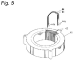
- Examples of these coils include a coil 43 (see Fig.4 ) prepared by cutting the insulated wire of the present invention in a prescribed length, and then subjecting it to a bending processing in the U-shaped form or the like, thereby preparing a plurality of wire segments 44, and then alternately connecting two open ends (terminals) 44a in the U-shaped form or the like of each wire segment 44, as shown in Fig. 5 .
- By heating the coil 43 at the temperature equal to or more than the hardening-starting temperature of the fusing layer adjacent fusing layers or the fusing layer and a slot 42 can be firmly fixed, so that the coil is fixed.
- the electrical/electronic equipment formed by using this coil is not particularly limited and examples of one preferable embodiment of such electrical/electronic equipment include a rotating electric machine equipped with a stator 40 shown in Fig. 4 (in particular, driving motors of HV and EV).
- This rotating electric machine can be made in the same constitution as the conventional one, except for equipment of the stator 40.
- the stator 40 can be made in the same constitution as the conventional one, except for its wire segment 44 being formed by the insulated wire of the present invention.
- the stator 40 has a stator core 41, and a coil 43 in which, as shown in such as Fig. 3 , wire segments 44 formed of the insulated wire of the present invention are incorporated in a slot 42 of the stator core 41 and open ends 44a of the wire segments 44 are electrically connected.
- This coil 43 is in the solidified state such that adjacent fusing layers, or the fusing layer and the slot 42 are firmly fixed.
- the wire segment 44 may be incorporated in the slot 42 with one segment. However, it is preferable that as shown in Fig. 4 , two segments are incorporated in pairs.
- the coil 43 formed by alternately connecting the open ends 44a that are two ends of the wire segments 44 which have been subjected to a bending processing as described above, is incorporated in the slot 42 of the stator core 41.
- the wire segment 44 may be incorporated in the slot 42 after connecting the open ends 44a thereof.
- the open ends 44a of the wire segment 44 may be subjected to a bending processing, thereby to connect them.
- the use of the conductor having a rectangular cross-sectional shape allows, for example, increase in a ratio (space factor) of the cross-sectional area of the conductor to the slot cross-sectional area of the stator core, whereby properties of the electrical/electronic equipment can be improved.
- the insulated wire shown in Fig. 1 was produced.
- C1, C2, and C3 indicate a cylinder temperature in the extruder, and respectively indicate 3-zone temperatures of the C1, C2 and C3 in the order from the resin-casting section.
- H indicates a temperature of the head section
- D indicates a temperature of the die section.
- a pre-wire (length: 500 mm) having a structure having the thermoplastic resin layer (thickness: 80 ⁇ m) on the outer periphery of the conductor 11 was prepared.
- each of the resins and a hardening agent were dissolved in methyl ethyl ketone (MEK) in the blend ratios shown in Table 1 to prepare a fusing layer-forming solution in which a total content of the resin and the hardening agent is the concentration of 20% by mass.
- MEK methyl ethyl ketone
- the 300 m-long pre-wire was soaked in the fusing layer-forming solution (25°C, 10 sec.), thereby to coat the fusing layer-forming solution on the outer periphery of the pre-wire.
- the pre-wire having the fusing layer-forming solution coated thereon was subjected to a heat treatment at 120°C for 5 min, thereby to vaporize MEK.
- a self-fusing insulated wire having a thermosetting fusing layer 13 (outermost layer, thickness: 30 ⁇ m) on the surface of the thermoplastic resin layer 12 was prepared.
- the above-described fusing layer-forming solution was coated in the film-shape on a flat surface of the glass plate and MEK was vaporized, thereby to obtain a film (a hardening resin composition constituting the fusing layer, thickness: 50 ⁇ m).
- the obtained film was subjected to a heat treatment at 190°C for 30 min to harden it, thereby to a hardened film (thickness: 50 ⁇ m).
- This hardened film was cut in rectangles of vertical 20 mm ⁇ horizontal 5 mm.
- a storage elastic modulus of this hardened film was measured by a dynamic viscoelasticity measuring device DMA8000 (manufactured by PerkinElmer, Inc.). In more detail, the storage elastic modulus was measured while rising a temperature up to the range of 50 to 250°C at the temperature-rising rate of 10 °C/min at 1Hz according to a tension mode, thereby to determine a storage elastic modulus at 85°C and a storage elastic modulus at 130°C.
- the glass transition point is a value measured while rising a temperature up to the range of 30 to 250°C at the temperature-rising rate of 10 °C/min using a differential scanning calorimetric analyzer (DSC-60, manufactured by Shimadzu Corporation).
- the glass transition point is an extrapolation glass transition starting temperature according to JIS K 7121 "Testing Methods for Transition Temperatures of Plastics".
- the above-described fusing layer-forming solution was subjected to a heat treatment at 120°C for 5 min to vaporize MEK.
- a residue from which MEK was removed (a hardening resin composition for forming the fusing layer) as a sample
- a DSC chart when the sample was temperature-elevated at the temperature-rising rate of 10 °C/min starting from 40°C was obtained by means of a differential scanning calorimetric analyzer (DSC-60, manufactured by Shimadzu Corporation).
- An apical temperature of the exothermic peak was defined as a peak exothermic temperature.
- the self-fusing insulated wire produced above was subjected to a heat treatment at 80°C for 168 hours and was wound around an iron core of ⁇ 2.5mm so that the short-sided surface of the cross-section thereof was directed toward the iron core (namely, 180°C bending processing was conducted).
- the folding endurance was evaluated by rating a case where the fusing layer did not crack as the evaluation A, whereas by rating a case where the fusing layer cracked as the evaluation C.
- the two self-fusing insulated wires produced above were firmly attached to each other by settling surfaces forming long sides of the cross section so as to be the settled wire length of 200 mm. Then, the settled wire was subjected to a heat treatment at 190°C for 30 min to firmly fix a whole attachment surface. This wire was left to stand in the environment of 25°C for 8 hrs., and then was set to a tensile tester (Autograph AGS-J, manufactured by Shimadzu Corporation), and both ends of the settled wires were pulled at the pulling rate of 50 mm/min in opposite directions with respect to one another. A strength required to fracture a firmly fixed state of the two wires was defined as a fixing strength and evaluation was conducted according to the following criteria.
- the two self-fusing insulated wires produced above were firmly attached to each other by settling surfaces forming long sides of the cross section so as to be the settled wire length of 200 mm. Then, the settled wire was subjected to a heat treatment at 190°C for 30 min to firmly fix a whole attachment surface. A pair of these wires were set to a tensile tester equipped with a thermostat (Autograph AGS-J, manufactured by Shimadzu Corporation, thermostat temperature: 200°C), and both ends of the settled wires were pulled at the pulling rate of 50 mm/min in opposite directions with respect to one another. A strength required to fracture a firmly fixed state of the two wires was defined as a fixing strength and evaluation was conducted according to the following criteria.
- the two self-fusing insulated wires produced above were firmly attached to each other by settling surfaces forming long sides of the cross section so as to be the settled wire length of 200 mm. Then, the settled wire was subjected to a heat treatment at 190°C for 30 min to firmly fix a whole attachment surface. This wire was left to stand in a thermostat (temperature: 200°C) for 1000 hrs. Next, the wire was left to stand in the environment of 25°C for 8 hrs., and then was set to a tensile tester (Autograph AGS-J, manufactured by Shimadzu Corporation), and both ends of the settled wires were pulled at the pulling rate of 50 mm/min in opposite directions with respect to one another. A strength required to fracture a firmly fixed state of the two wires was defined as a fixing strength and evaluation was conducted according to the following criteria.
- the two insulated wires produced above were firmly attached to each other by settling surfaces forming long sides of the cross section so as to be the settled wire length of 200 mm. Then, the settled wire was subjected to a heat treatment at 190°C for 30 min to firmly fix a whole attachment surface. This wire was soaked for 1000 hrs., in ATF oil heated at 150°C, and then was set to a tensile tester (Autograph AGS-J, manufactured by Shimadzu Corporation), and both ends of the settled wires were pulled at the pulling rate of 50 mm/min in opposite directions with respect to one another. A strength required to fracture a firmly fixed state of the two wires was defined as a fixing strength and evaluation was conducted according to the following criteria. Note that the soak in ATF oil was carried out at 150°C and measurement of the fixing strength was conducted at 25°C.
Landscapes
- Physics & Mathematics (AREA)
- Spectroscopy & Molecular Physics (AREA)
- Engineering & Computer Science (AREA)
- Power Engineering (AREA)
- Manufacturing & Machinery (AREA)
- Chemical & Material Sciences (AREA)
- Chemical Kinetics & Catalysis (AREA)
- Insulated Conductors (AREA)
- Organic Insulating Materials (AREA)
- Insulation, Fastening Of Motor, Generator Windings (AREA)
- Laminated Bodies (AREA)
Applications Claiming Priority (2)
| Application Number | Priority Date | Filing Date | Title |
|---|---|---|---|
| JP2015238082 | 2015-12-04 | ||
| PCT/JP2016/085599 WO2017094789A1 (ja) | 2015-12-04 | 2016-11-30 | 自己融着性絶縁電線、コイル及び電気・電子機器 |
Publications (2)
| Publication Number | Publication Date |
|---|---|
| EP3385960A1 true EP3385960A1 (de) | 2018-10-10 |
| EP3385960A4 EP3385960A4 (de) | 2019-07-31 |
Family
ID=58797339
Family Applications (1)
| Application Number | Title | Priority Date | Filing Date |
|---|---|---|---|
| EP16870726.3A Withdrawn EP3385960A4 (de) | 2015-12-04 | 2016-11-30 | Selbstschmelzbarer isolierter draht, spule und elektrische/elektronische vorrichtung |
Country Status (6)
| Country | Link |
|---|---|
| US (1) | US20180254120A1 (de) |
| EP (1) | EP3385960A4 (de) |
| JP (1) | JPWO2017094789A1 (de) |
| KR (1) | KR20180090255A (de) |
| CN (1) | CN108292543A (de) |
| WO (1) | WO2017094789A1 (de) |
Families Citing this family (7)
| Publication number | Priority date | Publication date | Assignee | Title |
|---|---|---|---|---|
| CN110799594B (zh) * | 2017-06-20 | 2022-10-14 | 索尔维特殊聚合物美国有限责任公司 | 层状结构 |
| CA3082476A1 (en) * | 2017-11-13 | 2019-05-16 | Essex Group, Inc. | Winding wire articles having internal cavities |
| WO2019102929A1 (ja) * | 2017-11-24 | 2019-05-31 | 住友電工ウインテック株式会社 | 自己融着性樹脂組成物及び自己融着性絶縁電線 |
| DE102018125567A1 (de) * | 2018-10-16 | 2020-04-16 | Bayerische Motoren Werke Aktiengesellschaft | Spule sowie stromerregte Synchronmaschine |
| CN111863409B (zh) * | 2020-09-03 | 2021-11-02 | 长兴索菲特电子股份有限公司 | 一种降噪型工字电感及其制造方法 |
| CA3222811A1 (en) * | 2021-06-21 | 2022-12-29 | Kazunori Ishikawa | Adhesive composition for laminating electromagnetic steel sheet |
| CN118318278A (zh) * | 2022-02-08 | 2024-07-09 | 埃赛克斯古河电磁线日本有限公司 | 绝缘电线、线圈、旋转电机和电气/电子设备 |
Family Cites Families (8)
| Publication number | Priority date | Publication date | Assignee | Title |
|---|---|---|---|---|
| JPS59159640A (ja) * | 1983-02-28 | 1984-09-10 | Fujikura Ltd | 自己接着性絶縁電線およびこれを用いた密閉形圧縮機用電動機 |
| JPH11297124A (ja) | 1998-04-03 | 1999-10-29 | Hitachi Cable Ltd | 耐熱自己融着性エナメル線 |
| JP2002358836A (ja) | 2001-06-04 | 2002-12-13 | Hitachi Cable Ltd | 自己融着性エナメル線 |
| JP5449012B2 (ja) * | 2010-05-06 | 2014-03-19 | 古河電気工業株式会社 | 絶縁電線、電気機器及び絶縁電線の製造方法 |
| JP5584657B2 (ja) * | 2011-07-08 | 2014-09-03 | 株式会社日立製作所 | 自己修復性積層構造体及び自己融着絶縁電線 |
| JP5391324B1 (ja) * | 2012-11-30 | 2014-01-15 | 古河電気工業株式会社 | 耐インバータサージ絶縁ワイヤ及びその製造方法 |
| WO2015121999A1 (ja) * | 2014-02-17 | 2015-08-20 | 株式会社日立製作所 | 絶縁電線、回転電機及び絶縁電線の製造方法 |
| JP2016039042A (ja) * | 2014-08-08 | 2016-03-22 | 株式会社日立製作所 | 絶縁電線、回転電機及び絶縁電線の製造方法 |
-
2016
- 2016-11-30 KR KR1020187012358A patent/KR20180090255A/ko not_active Ceased
- 2016-11-30 CN CN201680069317.8A patent/CN108292543A/zh active Pending
- 2016-11-30 JP JP2017554149A patent/JPWO2017094789A1/ja active Pending
- 2016-11-30 WO PCT/JP2016/085599 patent/WO2017094789A1/ja not_active Ceased
- 2016-11-30 EP EP16870726.3A patent/EP3385960A4/de not_active Withdrawn
-
2018
- 2018-05-03 US US15/970,482 patent/US20180254120A1/en not_active Abandoned
Also Published As
| Publication number | Publication date |
|---|---|
| CN108292543A (zh) | 2018-07-17 |
| EP3385960A4 (de) | 2019-07-31 |
| KR20180090255A (ko) | 2018-08-10 |
| JPWO2017094789A1 (ja) | 2018-09-20 |
| US20180254120A1 (en) | 2018-09-06 |
| WO2017094789A1 (ja) | 2017-06-08 |
Similar Documents
| Publication | Publication Date | Title |
|---|---|---|
| EP3385960A1 (de) | Selbstschmelzbarer isolierter draht, spule und elektrische/elektronische vorrichtung | |
| US10483013B2 (en) | Insulated wire excellent in bending resistance, as well as coil and electric or electronic equipment using the same | |
| EP3093855B1 (de) | Isolierter elektrischer draht, spule und elektrische/elektronische vorrichtung und rissvorbeugungsverfahren für isolierten elektrischen draht | |
| US10566109B2 (en) | Insulated wire, coil and electrical or electronic equipment | |
| JP6839695B2 (ja) | 絶縁電線、モーターコイルおよび電気・電子機器 | |
| EP3089170B1 (de) | Mehrlagiger isolierter draht, spule und elektrische/elektronische ausrüstung | |
| EP3754669A1 (de) | Isolierter draht, spule und elektrisches/elektronisches instrument | |
| JP6932642B2 (ja) | 絶縁電線、絶縁電線の製造方法、コイル、回転電機および電気・電子機器 | |
| EP3425640A1 (de) | Isolierter draht, spule und elektrische/elektronische vorrichtung | |
| EP3089169B1 (de) | Isolierter draht, spule und elektronische/elektrische vorrichtung | |
| US10366809B2 (en) | Insulated wire, coil, and electric or electronic equipment | |
| JP2017117681A (ja) | 自己融着性絶縁電線、コイル及び電気・電子機器 | |
| JP6490505B2 (ja) | 絶縁電線、コイル及び電気・電子機器 | |
| JP2010157433A (ja) | 絶縁電線 | |
| JP2010153290A (ja) | 絶縁電線 |
Legal Events
| Date | Code | Title | Description |
|---|---|---|---|
| STAA | Information on the status of an ep patent application or granted ep patent |
Free format text: STATUS: THE INTERNATIONAL PUBLICATION HAS BEEN MADE |
|
| PUAI | Public reference made under article 153(3) epc to a published international application that has entered the european phase |
Free format text: ORIGINAL CODE: 0009012 |
|
| STAA | Information on the status of an ep patent application or granted ep patent |
Free format text: STATUS: REQUEST FOR EXAMINATION WAS MADE |
|
| 17P | Request for examination filed |
Effective date: 20180427 |
|
| AK | Designated contracting states |
Kind code of ref document: A1 Designated state(s): AL AT BE BG CH CY CZ DE DK EE ES FI FR GB GR HR HU IE IS IT LI LT LU LV MC MK MT NL NO PL PT RO RS SE SI SK SM TR |
|
| AX | Request for extension of the european patent |
Extension state: BA ME |
|
| DAV | Request for validation of the european patent (deleted) | ||
| DAX | Request for extension of the european patent (deleted) | ||
| A4 | Supplementary search report drawn up and despatched |
Effective date: 20190703 |
|
| RIC1 | Information provided on ipc code assigned before grant |
Ipc: H01F 5/06 20060101ALI20190627BHEP Ipc: B32B 27/28 20060101ALI20190627BHEP Ipc: H01B 3/40 20060101ALI20190627BHEP Ipc: H01F 27/28 20060101ALI20190627BHEP Ipc: H01B 3/42 20060101ALI20190627BHEP Ipc: H01B 3/30 20060101ALI20190627BHEP Ipc: H02K 3/30 20060101ALI20190627BHEP Ipc: H01B 7/02 20060101AFI20190627BHEP Ipc: H02K 15/10 20060101ALI20190627BHEP Ipc: H01B 3/36 20060101ALI20190627BHEP Ipc: B32B 27/38 20060101ALI20190627BHEP |
|
| RAP1 | Party data changed (applicant data changed or rights of an application transferred) |
Owner name: ESSEX FURUKAWA MAGNET WIRE JAPAN CO., LTD. |
|
| STAA | Information on the status of an ep patent application or granted ep patent |
Free format text: STATUS: THE APPLICATION HAS BEEN WITHDRAWN |
|
| 18W | Application withdrawn |
Effective date: 20210512 |