EP3387264B1 - Pompe à fluide - Google Patents
Pompe à fluide Download PDFInfo
- Publication number
- EP3387264B1 EP3387264B1 EP16872988.7A EP16872988A EP3387264B1 EP 3387264 B1 EP3387264 B1 EP 3387264B1 EP 16872988 A EP16872988 A EP 16872988A EP 3387264 B1 EP3387264 B1 EP 3387264B1
- Authority
- EP
- European Patent Office
- Prior art keywords
- energizer
- pump
- controller
- fire
- input
- Prior art date
- Legal status (The legal status is an assumption and is not a legal conclusion. Google has not performed a legal analysis and makes no representation as to the accuracy of the status listed.)
- Not-in-force
Links
Images


Classifications
-
- F—MECHANICAL ENGINEERING; LIGHTING; HEATING; WEAPONS; BLASTING
- F04—POSITIVE - DISPLACEMENT MACHINES FOR LIQUIDS; PUMPS FOR LIQUIDS OR ELASTIC FLUIDS
- F04B—POSITIVE-DISPLACEMENT MACHINES FOR LIQUIDS; PUMPS
- F04B49/00—Control, e.g. of pump delivery, or pump pressure of, or safety measures for, machines, pumps, or pumping installations, not otherwise provided for, or of interest apart from, groups F04B1/00 - F04B47/00
- F04B49/06—Control using electricity
- F04B49/065—Control using electricity and making use of computers
-
- F—MECHANICAL ENGINEERING; LIGHTING; HEATING; WEAPONS; BLASTING
- F04—POSITIVE - DISPLACEMENT MACHINES FOR LIQUIDS; PUMPS FOR LIQUIDS OR ELASTIC FLUIDS
- F04B—POSITIVE-DISPLACEMENT MACHINES FOR LIQUIDS; PUMPS
- F04B19/00—Machines or pumps having pertinent characteristics not provided for in, or of interest apart from, groups F04B1/00 - F04B17/00
- F04B19/006—Micropumps
-
- F—MECHANICAL ENGINEERING; LIGHTING; HEATING; WEAPONS; BLASTING
- F04—POSITIVE - DISPLACEMENT MACHINES FOR LIQUIDS; PUMPS FOR LIQUIDS OR ELASTIC FLUIDS
- F04B—POSITIVE-DISPLACEMENT MACHINES FOR LIQUIDS; PUMPS
- F04B19/00—Machines or pumps having pertinent characteristics not provided for in, or of interest apart from, groups F04B1/00 - F04B17/00
- F04B19/20—Other positive-displacement pumps
- F04B19/24—Pumping by heat expansion of pumped fluid
-
- F—MECHANICAL ENGINEERING; LIGHTING; HEATING; WEAPONS; BLASTING
- F04—POSITIVE - DISPLACEMENT MACHINES FOR LIQUIDS; PUMPS FOR LIQUIDS OR ELASTIC FLUIDS
- F04B—POSITIVE-DISPLACEMENT MACHINES FOR LIQUIDS; PUMPS
- F04B43/00—Machines, pumps, or pumping installations having flexible working members
- F04B43/02—Machines, pumps, or pumping installations having flexible working members having plate-like flexible members, e.g. diaphragms
- F04B43/04—Pumps having electric drive
- F04B43/043—Micropumps
- F04B43/046—Micropumps with piezoelectric drive
Definitions
- This invention relates to the field of fluid pumps. More particularly, this invention relates to a microfluidic pump with a simplified electronic control interface.
- Microfluidic pumps are tiny devices that are manufactured using microelectronic device fabrication technologies, such as photolithographic patterning, wet and dry etching techniques, and thin film deposition processes. Thus, these devices are extremely small, and operate on very small volumes of fluid. As such, they are ideal for applications where a small device is required and small amounts of fluid are to be dispensed.
- microfluidic pump operates by expanding a bubble of the fluid within a channel, and then moving the bubble along the channel in one direction or the other, such that the bubble pushes the downstream volume of fluid along the channel in front of it, and pulls the upstream volume of fluid through the channel behind it.
- the pump is constructed with a plurality of devices disposed along the length of the channel, which devices are operable to at least one of create and maintain the bubble of fluid. These devices are typically operated in a timed, serial manner in one direction or the other along the length of the channel, and thus move the bubble as desired through the channel.
- the circuitry required to connect the pump to a controller is typically comparatively bulky, as a control line for each one of devices along the channel length is typically required.
- the additional size of the overall pump device that is required at least in part by the control lines tends to prevent the adoption and use of microfluidic pumps such as these in applications where their size is a critical factor.
- EP 2 269 725 A1 aims to provide a micropump device having good controllability over the amount of gas generated from the gas generating material and thus the amount of liquid fed by the micropump.
- the micropump device includes a micropump and a controller.
- the micropump includes: a microchannel serving as a channel for liquid, a gas generating material generating a gas upon exposure to light and supplying the gas to the microchannel, and a light source for irradiating the gas generating material with light.
- the controller supplies to the light source a control pulse signal that causes the light source to blink on and off in a binary manner by repeating a pulse train pattern composed of a fixed number of bits each capable of having two states, one of which is a first level allowing the light source to be turned on and the other of which is a second level allowing the light source to be turned off.
- US 2011/286493 A1 discloses a microcalorimeter system that includes a first microfluidic channel coupling a calorimeter with a sample chamber.
- a second microfluidic channel couples the calorimeter with a waste chamber.
- An inertial pump includes a fluid actuator integrated asymmetrically within the first microfluidic channel, and the fluid actuator is capable of selective activation to pump fluid from the sample chamber to the calorimeter and from the calorimeter to the waste chamber through the first and second microfluidic channels, respectively.
- EP 1 418 003 A1 discloses a microfluidic device including a fluidic pumping system, that includes a fluid-carrying channel, a plurality of acoustic pumping elements arranged along the fluid-carrying channel, wherein the acoustic pumping elements are configured to form an acoustic wave focused within the channel, and a controller in electrical communication with the plurality of acoustic pumping elements, the controller being configured to activate the acoustic pumping elements in such a manner as to cause the acoustic wave to move along the channel to move the fluid through the channel.
- a closed length of channel is disposed on the chip, where the channel has a first open end and a second open end.
- Energizers are disposed along the length of the channel, where each energizer is associated with a unique energizer designation.
- An first controller and energizer fire control lines are also disposed on the chip, one each of the energizer fire control lines electrically connecting one each of the energizers to the first controller.
- Inputs are electrically connected to the first controller, for connecting the first controller to an second controller that is not disposed on the chip.
- the inputs include a power input, an enable input, a pump direction input, and an energizer run length input.
- the first controller has circuitry to (a) receive from the second controller and selectively retain a pump direction on the pump direction input, (b) receive from the second controller and selectively retain an energizer run length on the energizer run length input, (c) receive from the second controller an enable on the enable input, (d) send a timed sequence of fire commands on the energizer fire control lines to a selected number of energizers that is equal to the energizer run length, starting with a stored starting energizer and ending with an ending energizer, and (e) update the stored starting energizer with the designation for the energizer next following the ending energizer.
- the energizers are heaters or piezoelectric devices.
- the energizer run length is an integer between 1 and 32. In some embodiments the energizer run length is equal to 8x, where x is an integer from 1 to 4.
- the timed sequence is a set time between each fire command, or is a variable time between each fire command, or is a selectable time between each fire command.
- the fluidic pump according to the present invention can reduce issues such as those described above, at least in part.
- a self-firing and cycling microfluidic pump according to an embodiment of the present invention is started and stopped with a single electrical signal.
- the pump features an internal oscillator and fire duty cycle selection options for the generated fire signal.
- the rank or order of the pump (the number of heaters in a single cycle of the pump) can be selected, as well as the direction of the pumping sequence.
- the internal voltage controlled oscillator (VCO) is tunable with an input voltage.
- Some embodiments of the pump only require three pins; a power, a ground, and an enable.
- the pump's internal sequencer selects the next firing heater using its internal sequencer.
- the on-chip VCO is used to generate the fire signal with a default that is sufficient to pump the fluid.
- FIG. 1 there is depicted a structural block diagram of a microfluidic pump system 10 according to an embodiment of the present invention. It is appreciated that not all of the elements as depicted in the figures are present in all embodiment of the present invention, and that the specific elements as described herein may vary in different embodiments. Thus, the description provided below is in regard to the depicted embodiment, and not all embodiments.
- the pump 10 includes a VCO 100, which produces a clock signal on line 110 for generating the pump firing signals and sequencing the state machine controlling the firing order.
- the VCO 100 receives an input 106 of a trim voltage for the VCO 100 frequency, and an enable 108 that turns the VCO clock on and off to enable/disable pump firing.
- the pump 10 fires in a cycle sequence, and when the VCO 100 is off (enable 108 is low), the pump 10 stops firing.
- the clock signal 110 is received by a fire signal generator 102, which produces as an output a fire signal 114 of a precise time width that is applied to the pump 122 selected in the state machine, as described in more detail hereafter.
- the fire signal generator 102 receives as an input a fire width 112, which is measured in a number of clock cycles as received on the clock line 110, and controls the fire signal 114 width.
- the fire width 112 determines the length of the fire signal 114, such as three clock pulses or nine clock pulses, or anything in-between as desired (for example).
- the fire signal generator 102 in some embodiments, has a default fire signal 114 width, and does not need an input 112 for a selectable fire width.
- the fire signal 114 is received as an input by the self-cycling pump control circuit 104, which controls the energizers 122 that are fired in sequence. Receipt of a fire signal 114 causes the pump controller 104 to initiate a firing sequence, or in other words, initiate sending power signals on lines 120 to the energizers 122 that are disposed in the channel structure 124 of the pump 10.
- the pump controller 104 receives as an input a direction signal 116. For example, in one embodiment a low state on the input 116 allows the pump controller 104 to fire the energizers 122 in what could be called a forward or normal direction. On the other hand, a high state on the input 116 causes the pump controller 104 to fire the energizers 122 in a reverse sequential order.
- the pump controller 104 also receives as input the length or rank of the pump sequence 118, or in other words the number of energizers 122 that should be powered in the firing cycle.
- the input 118 could indicate that 8, 16, 24, or 32 of the energizers 122 should be powered in a given sequence based upon receipt of a single fire signal 114.
- Each fire signal selects and powers the next energizer 122 in the sequence.
- the firing sequence advances to the first energizer 122 in the cycle, and then continues again from there.
- the energizers 122 are resistive heating elements, and in some embodiments the energizers 122 are piezoelectric devices.
- inputs 106, 112, 116, and 118 are set at default values, and no connection from the on-chip controller to any external controller is needed. In these embodiments, only three connections are made to the pump on the monolithic chip, which connections are the power 126, ground 128, and enable 108.
- FIGS. 2-5 depict more detailed depictions of the structural blocks of FIG. 1 , and thus disclose one way to implement the features of the present invention.
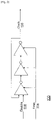
- FIG. 2 depicts the VCO 100 in greater detail.
- the topology depicted in FIG. 2 is a three inverter ring oscillator.
- the number of inverters may be increased, always using an odd number of inverters, to lower the frequency of the oscillator 100 to a desired value.
- the clock frequency is preset using a chip internal voltage, but can be over-driven with an external voltage 106.
- the enable signal 108 is a logic high to generate a logic high on the clock line 110. When the enable 108 is low, the clock output 110 is a logic low.
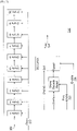
- FIG. 3 depicts the fire generator 102 in greater detail.
- the fire generator 102 generates a fire signal 114 from its input clock 110.
- the fire signal 114 has a preset default pulse width that is suited for the pump actuators, though in some embodiments the preset value may be overridden, such as for experimental purposes.
- the core of the fire generation 102 is a ten state machine 101 that recycles every ten states when the enable signal 108 is a logic high. Each input clock rising transition advances the state machine 101 to the next state.
- the enable 108 is a logic low
- the fire signal 114 is low.
- state 1 a reset-set latch is set and the fire signal 114 is a logic high.
- the RS latch is reset and the fire signal 114 now assumes a logic low level. In this manner, a repeating fire signal with a defined pulse width is present when the enable 108 is a logic high.
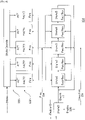
- FIG. 4 depicts the self-cycling pump controller 104 in greater detail.
- the pump controller 104 is a state machine that is illustrated in FIG. 4 with five states, although any number may be used.
- the state machine advances when the input enable signal 108 is a logic high with the rising transition of the input fire signal 114. When enable 108 is a logic low, the state machine stays in state 0 and no actuators are selected. The state machine default is advance to the next state, however the default may be overridden using the forward/reverse logic signal 116 to reverse the state order.
- the state decode logic block determines which pump actuators are to be fired, using the ACT signal 120 for each pump actuator 122.
- One example of a state decoder is to set the ACT 120 to a logic high for one pump 122 for each state, and advance to the next adjacent pump 122 for the next state.
- the state order repeats while the enable signal 108 is logic high, and remains in state 0 when the enable signal 108 is low.
- FIG. 5 depicts a pump actuator block in greater detail.
- the pump actuator block generates the driving signal for the pump actuator/heater.
- the block contains a logic AND and a MOS transistor switch to activate the pump heater.
- the HPWR signal is a voltage to set the correct pump heater current.
- ACT is low the pump heater is deactivated.
- the ACT signal is a logic high and the Fire signal is a logic high the MOS switch activates current through the heater. The current flows for the duration of the Fire signal and terminates when the Fire signal returns to a logic low. Therefore, the pump heater current flows for a time equal to the Fire input pulse width when the ACT signal is a logic high.
Landscapes
- Engineering & Computer Science (AREA)
- Mechanical Engineering (AREA)
- General Engineering & Computer Science (AREA)
- Computer Hardware Design (AREA)
- Reciprocating Pumps (AREA)
- Structures Of Non-Positive Displacement Pumps (AREA)
- Control Of Positive-Displacement Pumps (AREA)
Claims (8)
- Pompe fluidique (10), comprenant :une puce monolithique,une longueur de canal fermée disposée sur la puce, le canal ayant une première extrémité ouverte et une seconde extrémité ouverte,une pluralité de dispositifs d'excitation (122) disposés le long de la longueur du canal, chaque dispositif d'excitation (122) étant associé à une désignation de dispositif d'excitation unique,un premier contrôleur (104) disposé sur la puce,des lignes de commande de déclenchement de dispositif d'excitation (120) disposées sur la puce, chacune des lignes de commande de déclenchement de dispositif d'excitation (120) reliant électriquement chacun des dispositifs d'excitation (122) au premier contrôleur (104),des entrées (106, 112, 116, 118) reliées électriquement au premier contrôleur (104), pour relier le premier contrôleur (104) à un second contrôleur qui n'est pas disposé sur la puce, les entrées (106, 112, 116, 118) comprenant :une entrée d'alimentation,une entrée de validation,une entrée de direction de pompe, etune entrée de longueur de plage de dispositifs d'excitation,le premier contrôleur (104) ayant un circuit pour :recevoir à partir du second contrôleur et conserver sélectivement une direction de pompe sur l'entrée de direction de pompe,recevoir à partir du second contrôleur et conserver sélectivement une longueur de plage de dispositifs d'excitation sur l'entrée de longueur de plage de dispositifs d'excitation,recevoir à partir du second contrôleur une validation sur l'entrée de validation,envoyer une séquence temporisée de commandes de déclenchement sur les lignes de commande de déclenchement de dispositif d'excitation à un nombre sélectionné de dispositifs d'excitation (122) qui est égal à la longueur de plage de dispositifs d'excitation, en commençant par un dispositif d'excitation de début enregistré et en terminant par un dispositif d'excitation de fin, etmettre à jour le dispositif d'excitation de début enregistré avec la désignation du dispositif d'excitation qui suit immédiatement le dispositif d'excitation de fin.
- Pompe fluidique (10) selon la revendication 1, dans laquelle les dispositifs d'excitation (122) sont des filaments chauffants.
- Pompe fluidique (10) selon la revendication 1, dans laquelle les dispositifs d'excitation (122) sont des dispositifs piézoélectriques.
- Pompe fluidique (10) selon l'une quelconque des revendications 1 à 3, dans laquelle la longueur de plage de dispositifs d'excitation est un nombre entier compris entre 1 et 32.
- Pompe fluidique (10) selon l'une quelconque des revendications 1 à 3, dans laquelle la longueur de plage de dispositifs d'excitation est égale à 8x, où x est un nombre entier de 1 à 4.
- Pompe fluidique (10) selon l'une quelconque des revendications 1 à 5, dans laquelle la séquence temporisée comprend un temps défini entre chaque commande de déclenchement.
- Pompe fluidique (10) selon l'une quelconque des revendications 1 à 5, dans laquelle la séquence temporisée comprend un temps variable entre chaque commande de déclenchement.
- Pompe fluidique (10) selon l'une quelconque des revendications 1 à 5, dans laquelle la séquence temporisée comprend un temps sélectionnable entre chaque commande de déclenchement.
Priority Applications (1)
| Application Number | Priority Date | Filing Date | Title |
|---|---|---|---|
| EP22152139.6A EP4006357A1 (fr) | 2015-12-11 | 2016-12-06 | Pompe fluidique |
Applications Claiming Priority (2)
| Application Number | Priority Date | Filing Date | Title |
|---|---|---|---|
| US14/966,194 US9989049B2 (en) | 2015-12-11 | 2015-12-11 | Microfluidic pump |
| PCT/JP2016/086277 WO2017099090A1 (fr) | 2015-12-11 | 2016-12-06 | Pompe à fluide |
Related Child Applications (2)
| Application Number | Title | Priority Date | Filing Date |
|---|---|---|---|
| EP22152139.6A Division-Into EP4006357A1 (fr) | 2015-12-11 | 2016-12-06 | Pompe fluidique |
| EP22152139.6A Division EP4006357A1 (fr) | 2015-12-11 | 2016-12-06 | Pompe fluidique |
Publications (3)
| Publication Number | Publication Date |
|---|---|
| EP3387264A1 EP3387264A1 (fr) | 2018-10-17 |
| EP3387264A4 EP3387264A4 (fr) | 2019-08-21 |
| EP3387264B1 true EP3387264B1 (fr) | 2022-04-27 |
Family
ID=59014161
Family Applications (2)
| Application Number | Title | Priority Date | Filing Date |
|---|---|---|---|
| EP22152139.6A Pending EP4006357A1 (fr) | 2015-12-11 | 2016-12-06 | Pompe fluidique |
| EP16872988.7A Not-in-force EP3387264B1 (fr) | 2015-12-11 | 2016-12-06 | Pompe à fluide |
Family Applications Before (1)
| Application Number | Title | Priority Date | Filing Date |
|---|---|---|---|
| EP22152139.6A Pending EP4006357A1 (fr) | 2015-12-11 | 2016-12-06 | Pompe fluidique |
Country Status (5)
| Country | Link |
|---|---|
| US (1) | US9989049B2 (fr) |
| EP (2) | EP4006357A1 (fr) |
| JP (1) | JP6773113B2 (fr) |
| CN (1) | CN108368857B (fr) |
| WO (1) | WO2017099090A1 (fr) |
Families Citing this family (7)
| Publication number | Priority date | Publication date | Assignee | Title |
|---|---|---|---|---|
| US10334879B2 (en) * | 2015-12-21 | 2019-07-02 | Funai Electric Co., Ltd | Method and apparatus for metering and vaporizing a fluid |
| US10212444B2 (en) * | 2016-01-15 | 2019-02-19 | Qualcomm Incorporated | Multi-type-tree framework for video coding |
| KR102777282B1 (ko) | 2016-05-10 | 2025-03-10 | 삼성전자주식회사 | 영상을 부호화/복호화 하는 방법 및 그 장치 |
| CN109412580B (zh) * | 2017-08-17 | 2022-05-03 | 深圳指芯智能科技有限公司 | 选择电路 |
| WO2021144396A1 (fr) | 2020-01-17 | 2021-07-22 | F. Hoffmann-La Roche Ag | Dispositif microfluidique et procédé de synthèse automatisée par division de groupe |
| US20230039014A1 (en) | 2020-01-22 | 2023-02-09 | Roche Sequencing Solutions, Inc. | Microfluidic bead trapping devices and methods for next generation sequencing library preparation |
| CN116710571A (zh) | 2020-10-15 | 2023-09-05 | 卡帕生物系统公司 | 用于下一代测序文库制备的电泳装置和方法 |
Family Cites Families (40)
| Publication number | Priority date | Publication date | Assignee | Title |
|---|---|---|---|---|
| JPH02275067A (ja) | 1989-04-15 | 1990-11-09 | Toyota Autom Loom Works Ltd | ポンプ |
| US6273687B1 (en) | 1998-11-26 | 2001-08-14 | Aisin Seiki Kabushiki Kaisha | Micromachined pump apparatus |
| US7672059B2 (en) * | 2000-10-20 | 2010-03-02 | Holochip Corporation | Fluidic lens with electrostatic actuation |
| JP2004532743A (ja) | 2000-10-25 | 2004-10-28 | ワシントン ステート ユニバーシティ リサーチ ファウンデーション | 圧電マイクロトランスデューサ、その使用法および製造法 |
| WO2003015890A1 (fr) * | 2001-08-20 | 2003-02-27 | President And Fellows Of Harvard College | Jeux ordonnes d'echantillons fluides et procede d'utilisation |
| JP2003260795A (ja) | 2002-03-12 | 2003-09-16 | Ricoh Co Ltd | 液滴吐出ヘッド及びインクジェット記録装置 |
| DE10222228A1 (de) | 2002-05-16 | 2003-11-27 | Roche Diagnostics Gmbh | Mikropumpe mit Heizelementen für einen pulsierten Betrieb |
| US7455770B2 (en) * | 2002-09-09 | 2008-11-25 | Cytonome, Inc. | Implementation of microfluidic components in a microfluidic system |
| US6811385B2 (en) * | 2002-10-31 | 2004-11-02 | Hewlett-Packard Development Company, L.P. | Acoustic micro-pump |
| US7445926B2 (en) * | 2002-12-30 | 2008-11-04 | The Regents Of The University Of California | Fluid control structures in microfluidic devices |
| FR2861142B1 (fr) * | 2003-10-16 | 2006-02-03 | Mecanique Magnetique Sa | Pompe a vide turbo moleculaire |
| KR100629502B1 (ko) | 2004-12-07 | 2006-09-28 | 삼성전자주식회사 | 마이크로 펌프 |
| US7213473B2 (en) * | 2004-12-15 | 2007-05-08 | Sandia National Laboratories | Sample preparation system for microfluidic applications |
| US7727363B2 (en) * | 2005-02-02 | 2010-06-01 | Ut-Battelle, Llc | Microfluidic device and methods for focusing fluid streams using electroosmotically induced pressures |
| AU2006283177B2 (en) * | 2005-08-23 | 2011-11-17 | University Of Virginia Patent Foundation | Passive components for micro-fluidic flow profile shaping and related method thereof |
| US7611673B2 (en) * | 2005-09-28 | 2009-11-03 | California Institute Of Technology | PMDS microfluidic components and methods of operation of the same |
| US7766033B2 (en) * | 2006-03-22 | 2010-08-03 | The Regents Of The University Of California | Multiplexed latching valves for microfluidic devices and processors |
| US8137626B2 (en) * | 2006-05-19 | 2012-03-20 | California Institute Of Technology | Fluorescence detector, filter device and related methods |
| US7790118B2 (en) * | 2006-10-18 | 2010-09-07 | California Institute Of Technology | Microfluidic devices and related methods and systems |
| JP4856733B2 (ja) * | 2008-04-28 | 2012-01-18 | 積水化学工業株式会社 | マイクロポンプ装置 |
| US8158082B2 (en) * | 2008-08-29 | 2012-04-17 | Incube Labs, Llc | Micro-fluidic device |
| KR20110111449A (ko) * | 2008-12-31 | 2011-10-11 | 인터젠엑스 인크. | 미세유체 칩을 갖는 기구 |
| US8551787B2 (en) * | 2009-07-23 | 2013-10-08 | Fluidigm Corporation | Microfluidic devices and methods for binary mixing |
| DE102009035292A1 (de) * | 2009-07-30 | 2011-02-03 | Karlsruher Institut für Technologie | Vorrichtung zum Steuern des Durchflusses von Fluiden durch mikrofluidische Kanäle, Verfahren zu ihrem Betrieb und ihre Verwendung |
| WO2013134741A2 (fr) * | 2012-03-08 | 2013-09-12 | Cyvek, Inc. | Procédés et systèmes de fabrication de systèmes d'analyse de microréseaux, de mise en oeuvre d'analyses microfluidiques, et de surveillance et de balayage pour obtenir des résultats d'analyse microfluidique |
| US9700889B2 (en) * | 2009-11-23 | 2017-07-11 | Cyvek, Inc. | Methods and systems for manufacture of microarray assay systems, conducting microfluidic assays, and monitoring and scanning to obtain microfluidic assay results |
| US9651568B2 (en) * | 2009-11-23 | 2017-05-16 | Cyvek, Inc. | Methods and systems for epi-fluorescent monitoring and scanning for microfluidic assays |
| CN101813079A (zh) * | 2009-12-11 | 2010-08-25 | 北京工业大学 | 无阀热驱动泵 |
| EP2571696B1 (fr) | 2010-05-21 | 2019-08-07 | Hewlett-Packard Development Company, L.P. | Dispositif d'éjection de fluide comprenant une pompe de circulation |
| US9395050B2 (en) * | 2010-05-21 | 2016-07-19 | Hewlett-Packard Development Company, L.P. | Microfluidic systems and networks |
| US8720209B1 (en) * | 2010-10-06 | 2014-05-13 | Lawrence Livermore National Security, Llc | Solid state rapid thermocycling |
| JP5682513B2 (ja) * | 2011-09-06 | 2015-03-11 | 株式会社村田製作所 | 流体制御装置 |
| US9725687B2 (en) * | 2011-12-09 | 2017-08-08 | President And Fellows Of Harvard College | Integrated human organ-on-chip microphysiological systems |
| US8891949B2 (en) | 2012-02-03 | 2014-11-18 | Lexmark International, Inc. | Micro-fluidic pump |
| US9322014B1 (en) * | 2012-11-28 | 2016-04-26 | Sandia Corporation | Multiplexed microfluidic approach for nucleic acid enrichment |
| ITTO20130161A1 (it) * | 2013-02-27 | 2014-08-28 | Aar Aerospace Consulting L L C | Pompa micro-fluidica a forza di taglio |
| EP3058367B1 (fr) * | 2013-10-16 | 2019-01-09 | President and Fellows of Harvard College | Dispositif microfluidique pour la surveillance clinique en temps réel et l'évaluation quantitative de la coagulation du sang total |
| CN104912779A (zh) * | 2014-03-10 | 2015-09-16 | 松下知识产权经营株式会社 | 微泵和微阀的驱动装置以及使用该驱动装置的微流体设备 |
| US9797524B2 (en) * | 2014-09-12 | 2017-10-24 | The Regents Of The University Of California | Microfluidic logic circuit |
| CN108348002A (zh) * | 2015-05-15 | 2018-07-31 | 约翰·卡梅伦 | 用于电子蒸汽装置的汽化材料处理 |
-
2015
- 2015-12-11 US US14/966,194 patent/US9989049B2/en active Active
-
2016
- 2016-12-06 WO PCT/JP2016/086277 patent/WO2017099090A1/fr not_active Ceased
- 2016-12-06 JP JP2018519776A patent/JP6773113B2/ja active Active
- 2016-12-06 EP EP22152139.6A patent/EP4006357A1/fr active Pending
- 2016-12-06 CN CN201680071571.1A patent/CN108368857B/zh not_active Expired - Fee Related
- 2016-12-06 EP EP16872988.7A patent/EP3387264B1/fr not_active Not-in-force
Also Published As
| Publication number | Publication date |
|---|---|
| CN108368857A (zh) | 2018-08-03 |
| EP3387264A1 (fr) | 2018-10-17 |
| EP3387264A4 (fr) | 2019-08-21 |
| JP2018536795A (ja) | 2018-12-13 |
| CN108368857B (zh) | 2021-03-12 |
| EP4006357A1 (fr) | 2022-06-01 |
| US20170167481A1 (en) | 2017-06-15 |
| US9989049B2 (en) | 2018-06-05 |
| JP6773113B2 (ja) | 2020-10-21 |
| WO2017099090A1 (fr) | 2017-06-15 |
Similar Documents
| Publication | Publication Date | Title |
|---|---|---|
| EP3387264B1 (fr) | Pompe à fluide | |
| TWI337692B (en) | Methods of forming a power controller and controlling a power supply, and power supply controller | |
| JP2005538670A (ja) | モジュラチャージポンプアーキテクチャ | |
| TWI489777B (zh) | 開關調節器、其控制電路及其控制方法 | |
| CN102529367B (zh) | 静电电容性致动器的驱动装置 | |
| JP5121331B2 (ja) | 微細気泡発生装置 | |
| TW201105023A (en) | Flexible low current oscillator for multiphase operations | |
| CN1694193B (zh) | 低功率螺线管驱动电路 | |
| CN109428572A (zh) | 半导体装置和半导体装置的断电方法 | |
| TWI361568B (en) | Delay-locked loop and a method for providing charge signal to a charge pump of the same | |
| US10294645B2 (en) | Sanitary washing device | |
| US20050110819A1 (en) | Apparatus for controlling a temperature of an ink-jet printhead | |
| JP2001244799A (ja) | 電圧制御回路 | |
| US9673826B2 (en) | Receiving device | |
| JP2006066654A (ja) | レーザダイオード駆動回路 | |
| JP5710405B2 (ja) | 昇圧装置 | |
| WO2014181100A1 (fr) | Circuit actionneur de tête d'impression | |
| JP6011389B2 (ja) | 電源制御回路および電源装置 | |
| JP2019164947A (ja) | プラズマ装置用電源装置 | |
| KR950009246B1 (ko) | 주파수 카운터 제어회로 | |
| TW200929850A (en) | Variable frequency oscillating circuit | |
| JPS6137466B2 (fr) | ||
| JP6711399B2 (ja) | 微小流体装置 | |
| JP2023066256A (ja) | 遅延パルス生成回路 | |
| JPS58187699A (ja) | 液体移送装置及びその移送方法 |
Legal Events
| Date | Code | Title | Description |
|---|---|---|---|
| STAA | Information on the status of an ep patent application or granted ep patent |
Free format text: STATUS: THE INTERNATIONAL PUBLICATION HAS BEEN MADE |
|
| PUAI | Public reference made under article 153(3) epc to a published international application that has entered the european phase |
Free format text: ORIGINAL CODE: 0009012 |
|
| STAA | Information on the status of an ep patent application or granted ep patent |
Free format text: STATUS: REQUEST FOR EXAMINATION WAS MADE |
|
| 17P | Request for examination filed |
Effective date: 20180606 |
|
| AK | Designated contracting states |
Kind code of ref document: A1 Designated state(s): AL AT BE BG CH CY CZ DE DK EE ES FI FR GB GR HR HU IE IS IT LI LT LU LV MC MK MT NL NO PL PT RO RS SE SI SK SM TR |
|
| AX | Request for extension of the european patent |
Extension state: BA ME |
|
| DAV | Request for validation of the european patent (deleted) | ||
| DAX | Request for extension of the european patent (deleted) | ||
| A4 | Supplementary search report drawn up and despatched |
Effective date: 20190719 |
|
| RIC1 | Information provided on ipc code assigned before grant |
Ipc: F04F 1/18 20060101ALI20190715BHEP Ipc: F04B 19/00 20060101ALI20190715BHEP Ipc: F04D 33/00 20060101AFI20190715BHEP Ipc: F04B 49/06 20060101ALI20190715BHEP Ipc: F04B 43/04 20060101ALI20190715BHEP Ipc: F04B 19/24 20060101ALI20190715BHEP Ipc: F04F 1/06 20060101ALI20190715BHEP |
|
| GRAP | Despatch of communication of intention to grant a patent |
Free format text: ORIGINAL CODE: EPIDOSNIGR1 |
|
| STAA | Information on the status of an ep patent application or granted ep patent |
Free format text: STATUS: GRANT OF PATENT IS INTENDED |
|
| INTG | Intention to grant announced |
Effective date: 20211214 |
|
| GRAS | Grant fee paid |
Free format text: ORIGINAL CODE: EPIDOSNIGR3 |
|
| GRAA | (expected) grant |
Free format text: ORIGINAL CODE: 0009210 |
|
| STAA | Information on the status of an ep patent application or granted ep patent |
Free format text: STATUS: THE PATENT HAS BEEN GRANTED |
|
| AK | Designated contracting states |
Kind code of ref document: B1 Designated state(s): AL AT BE BG CH CY CZ DE DK EE ES FI FR GB GR HR HU IE IS IT LI LT LU LV MC MK MT NL NO PL PT RO RS SE SI SK SM TR |
|
| REG | Reference to a national code |
Ref country code: GB Ref legal event code: FG4D |
|
| REG | Reference to a national code |
Ref country code: CH Ref legal event code: EP |
|
| REG | Reference to a national code |
Ref country code: DE Ref legal event code: R096 Ref document number: 602016071599 Country of ref document: DE |
|
| REG | Reference to a national code |
Ref country code: AT Ref legal event code: REF Ref document number: 1487121 Country of ref document: AT Kind code of ref document: T Effective date: 20220515 |
|
| REG | Reference to a national code |
Ref country code: IE Ref legal event code: FG4D |
|
| REG | Reference to a national code |
Ref country code: LT Ref legal event code: MG9D |
|
| REG | Reference to a national code |
Ref country code: NL Ref legal event code: MP Effective date: 20220427 |
|
| REG | Reference to a national code |
Ref country code: AT Ref legal event code: MK05 Ref document number: 1487121 Country of ref document: AT Kind code of ref document: T Effective date: 20220427 |
|
| PG25 | Lapsed in a contracting state [announced via postgrant information from national office to epo] |
Ref country code: NL Free format text: LAPSE BECAUSE OF FAILURE TO SUBMIT A TRANSLATION OF THE DESCRIPTION OR TO PAY THE FEE WITHIN THE PRESCRIBED TIME-LIMIT Effective date: 20220427 |
|
| PG25 | Lapsed in a contracting state [announced via postgrant information from national office to epo] |
Ref country code: SE Free format text: LAPSE BECAUSE OF FAILURE TO SUBMIT A TRANSLATION OF THE DESCRIPTION OR TO PAY THE FEE WITHIN THE PRESCRIBED TIME-LIMIT Effective date: 20220427 Ref country code: PT Free format text: LAPSE BECAUSE OF FAILURE TO SUBMIT A TRANSLATION OF THE DESCRIPTION OR TO PAY THE FEE WITHIN THE PRESCRIBED TIME-LIMIT Effective date: 20220829 Ref country code: NO Free format text: LAPSE BECAUSE OF FAILURE TO SUBMIT A TRANSLATION OF THE DESCRIPTION OR TO PAY THE FEE WITHIN THE PRESCRIBED TIME-LIMIT Effective date: 20220727 Ref country code: LT Free format text: LAPSE BECAUSE OF FAILURE TO SUBMIT A TRANSLATION OF THE DESCRIPTION OR TO PAY THE FEE WITHIN THE PRESCRIBED TIME-LIMIT Effective date: 20220427 Ref country code: HR Free format text: LAPSE BECAUSE OF FAILURE TO SUBMIT A TRANSLATION OF THE DESCRIPTION OR TO PAY THE FEE WITHIN THE PRESCRIBED TIME-LIMIT Effective date: 20220427 Ref country code: GR Free format text: LAPSE BECAUSE OF FAILURE TO SUBMIT A TRANSLATION OF THE DESCRIPTION OR TO PAY THE FEE WITHIN THE PRESCRIBED TIME-LIMIT Effective date: 20220728 Ref country code: FI Free format text: LAPSE BECAUSE OF FAILURE TO SUBMIT A TRANSLATION OF THE DESCRIPTION OR TO PAY THE FEE WITHIN THE PRESCRIBED TIME-LIMIT Effective date: 20220427 Ref country code: ES Free format text: LAPSE BECAUSE OF FAILURE TO SUBMIT A TRANSLATION OF THE DESCRIPTION OR TO PAY THE FEE WITHIN THE PRESCRIBED TIME-LIMIT Effective date: 20220427 Ref country code: BG Free format text: LAPSE BECAUSE OF FAILURE TO SUBMIT A TRANSLATION OF THE DESCRIPTION OR TO PAY THE FEE WITHIN THE PRESCRIBED TIME-LIMIT Effective date: 20220727 Ref country code: AT Free format text: LAPSE BECAUSE OF FAILURE TO SUBMIT A TRANSLATION OF THE DESCRIPTION OR TO PAY THE FEE WITHIN THE PRESCRIBED TIME-LIMIT Effective date: 20220427 |
|
| PG25 | Lapsed in a contracting state [announced via postgrant information from national office to epo] |
Ref country code: RS Free format text: LAPSE BECAUSE OF FAILURE TO SUBMIT A TRANSLATION OF THE DESCRIPTION OR TO PAY THE FEE WITHIN THE PRESCRIBED TIME-LIMIT Effective date: 20220427 Ref country code: PL Free format text: LAPSE BECAUSE OF FAILURE TO SUBMIT A TRANSLATION OF THE DESCRIPTION OR TO PAY THE FEE WITHIN THE PRESCRIBED TIME-LIMIT Effective date: 20220427 Ref country code: LV Free format text: LAPSE BECAUSE OF FAILURE TO SUBMIT A TRANSLATION OF THE DESCRIPTION OR TO PAY THE FEE WITHIN THE PRESCRIBED TIME-LIMIT Effective date: 20220427 Ref country code: IS Free format text: LAPSE BECAUSE OF FAILURE TO SUBMIT A TRANSLATION OF THE DESCRIPTION OR TO PAY THE FEE WITHIN THE PRESCRIBED TIME-LIMIT Effective date: 20220827 |
|
| REG | Reference to a national code |
Ref country code: DE Ref legal event code: R097 Ref document number: 602016071599 Country of ref document: DE |
|
| PG25 | Lapsed in a contracting state [announced via postgrant information from national office to epo] |
Ref country code: SM Free format text: LAPSE BECAUSE OF FAILURE TO SUBMIT A TRANSLATION OF THE DESCRIPTION OR TO PAY THE FEE WITHIN THE PRESCRIBED TIME-LIMIT Effective date: 20220427 Ref country code: SK Free format text: LAPSE BECAUSE OF FAILURE TO SUBMIT A TRANSLATION OF THE DESCRIPTION OR TO PAY THE FEE WITHIN THE PRESCRIBED TIME-LIMIT Effective date: 20220427 Ref country code: RO Free format text: LAPSE BECAUSE OF FAILURE TO SUBMIT A TRANSLATION OF THE DESCRIPTION OR TO PAY THE FEE WITHIN THE PRESCRIBED TIME-LIMIT Effective date: 20220427 Ref country code: EE Free format text: LAPSE BECAUSE OF FAILURE TO SUBMIT A TRANSLATION OF THE DESCRIPTION OR TO PAY THE FEE WITHIN THE PRESCRIBED TIME-LIMIT Effective date: 20220427 Ref country code: DK Free format text: LAPSE BECAUSE OF FAILURE TO SUBMIT A TRANSLATION OF THE DESCRIPTION OR TO PAY THE FEE WITHIN THE PRESCRIBED TIME-LIMIT Effective date: 20220427 Ref country code: CZ Free format text: LAPSE BECAUSE OF FAILURE TO SUBMIT A TRANSLATION OF THE DESCRIPTION OR TO PAY THE FEE WITHIN THE PRESCRIBED TIME-LIMIT Effective date: 20220427 |
|
| PLBE | No opposition filed within time limit |
Free format text: ORIGINAL CODE: 0009261 |
|
| STAA | Information on the status of an ep patent application or granted ep patent |
Free format text: STATUS: NO OPPOSITION FILED WITHIN TIME LIMIT |
|
| PG25 | Lapsed in a contracting state [announced via postgrant information from national office to epo] |
Ref country code: AL Free format text: LAPSE BECAUSE OF FAILURE TO SUBMIT A TRANSLATION OF THE DESCRIPTION OR TO PAY THE FEE WITHIN THE PRESCRIBED TIME-LIMIT Effective date: 20220427 |
|
| 26N | No opposition filed |
Effective date: 20230130 |
|
| PG25 | Lapsed in a contracting state [announced via postgrant information from national office to epo] |
Ref country code: SI Free format text: LAPSE BECAUSE OF FAILURE TO SUBMIT A TRANSLATION OF THE DESCRIPTION OR TO PAY THE FEE WITHIN THE PRESCRIBED TIME-LIMIT Effective date: 20220427 |
|
| REG | Reference to a national code |
Ref country code: CH Ref legal event code: PL |
|
| GBPC | Gb: european patent ceased through non-payment of renewal fee |
Effective date: 20221206 |
|
| REG | Reference to a national code |
Ref country code: BE Ref legal event code: MM Effective date: 20221231 |
|
| PG25 | Lapsed in a contracting state [announced via postgrant information from national office to epo] |
Ref country code: LU Free format text: LAPSE BECAUSE OF NON-PAYMENT OF DUE FEES Effective date: 20221206 |
|
| PG25 | Lapsed in a contracting state [announced via postgrant information from national office to epo] |
Ref country code: LI Free format text: LAPSE BECAUSE OF NON-PAYMENT OF DUE FEES Effective date: 20221231 Ref country code: IE Free format text: LAPSE BECAUSE OF NON-PAYMENT OF DUE FEES Effective date: 20221206 Ref country code: GB Free format text: LAPSE BECAUSE OF NON-PAYMENT OF DUE FEES Effective date: 20221206 Ref country code: CH Free format text: LAPSE BECAUSE OF NON-PAYMENT OF DUE FEES Effective date: 20221231 |
|
| PG25 | Lapsed in a contracting state [announced via postgrant information from national office to epo] |
Ref country code: FR Free format text: LAPSE BECAUSE OF NON-PAYMENT OF DUE FEES Effective date: 20221231 Ref country code: BE Free format text: LAPSE BECAUSE OF NON-PAYMENT OF DUE FEES Effective date: 20221231 |
|
| PG25 | Lapsed in a contracting state [announced via postgrant information from national office to epo] |
Ref country code: IT Free format text: LAPSE BECAUSE OF FAILURE TO SUBMIT A TRANSLATION OF THE DESCRIPTION OR TO PAY THE FEE WITHIN THE PRESCRIBED TIME-LIMIT Effective date: 20220427 |
|
| PGFP | Annual fee paid to national office [announced via postgrant information from national office to epo] |
Ref country code: DE Payment date: 20231031 Year of fee payment: 8 |
|
| PG25 | Lapsed in a contracting state [announced via postgrant information from national office to epo] |
Ref country code: HU Free format text: LAPSE BECAUSE OF FAILURE TO SUBMIT A TRANSLATION OF THE DESCRIPTION OR TO PAY THE FEE WITHIN THE PRESCRIBED TIME-LIMIT; INVALID AB INITIO Effective date: 20161206 |
|
| PG25 | Lapsed in a contracting state [announced via postgrant information from national office to epo] |
Ref country code: CY Free format text: LAPSE BECAUSE OF FAILURE TO SUBMIT A TRANSLATION OF THE DESCRIPTION OR TO PAY THE FEE WITHIN THE PRESCRIBED TIME-LIMIT Effective date: 20220427 |
|
| PG25 | Lapsed in a contracting state [announced via postgrant information from national office to epo] |
Ref country code: MK Free format text: LAPSE BECAUSE OF FAILURE TO SUBMIT A TRANSLATION OF THE DESCRIPTION OR TO PAY THE FEE WITHIN THE PRESCRIBED TIME-LIMIT Effective date: 20220427 |
|
| PG25 | Lapsed in a contracting state [announced via postgrant information from national office to epo] |
Ref country code: MC Free format text: LAPSE BECAUSE OF FAILURE TO SUBMIT A TRANSLATION OF THE DESCRIPTION OR TO PAY THE FEE WITHIN THE PRESCRIBED TIME-LIMIT Effective date: 20220427 |
|
| PG25 | Lapsed in a contracting state [announced via postgrant information from national office to epo] |
Ref country code: TR Free format text: LAPSE BECAUSE OF FAILURE TO SUBMIT A TRANSLATION OF THE DESCRIPTION OR TO PAY THE FEE WITHIN THE PRESCRIBED TIME-LIMIT Effective date: 20220427 Ref country code: MC Free format text: LAPSE BECAUSE OF FAILURE TO SUBMIT A TRANSLATION OF THE DESCRIPTION OR TO PAY THE FEE WITHIN THE PRESCRIBED TIME-LIMIT Effective date: 20220427 |
|
| PG25 | Lapsed in a contracting state [announced via postgrant information from national office to epo] |
Ref country code: MT Free format text: LAPSE BECAUSE OF FAILURE TO SUBMIT A TRANSLATION OF THE DESCRIPTION OR TO PAY THE FEE WITHIN THE PRESCRIBED TIME-LIMIT Effective date: 20220427 |
|
| PG25 | Lapsed in a contracting state [announced via postgrant information from national office to epo] |
Ref country code: BG Free format text: LAPSE BECAUSE OF FAILURE TO SUBMIT A TRANSLATION OF THE DESCRIPTION OR TO PAY THE FEE WITHIN THE PRESCRIBED TIME-LIMIT Effective date: 20220427 |
|
| PG25 | Lapsed in a contracting state [announced via postgrant information from national office to epo] |
Ref country code: BG Free format text: LAPSE BECAUSE OF FAILURE TO SUBMIT A TRANSLATION OF THE DESCRIPTION OR TO PAY THE FEE WITHIN THE PRESCRIBED TIME-LIMIT Effective date: 20220427 |
|
| REG | Reference to a national code |
Ref country code: DE Ref legal event code: R119 Ref document number: 602016071599 Country of ref document: DE |
|
| PG25 | Lapsed in a contracting state [announced via postgrant information from national office to epo] |
Ref country code: DE Free format text: LAPSE BECAUSE OF NON-PAYMENT OF DUE FEES Effective date: 20250701 |