EP3387954B1 - Dispositif de suspension pour suspendre un meuble sur un mur et utilisation d'un tel dispositif de suspension - Google Patents
Dispositif de suspension pour suspendre un meuble sur un mur et utilisation d'un tel dispositif de suspension Download PDFInfo
- Publication number
- EP3387954B1 EP3387954B1 EP18165586.1A EP18165586A EP3387954B1 EP 3387954 B1 EP3387954 B1 EP 3387954B1 EP 18165586 A EP18165586 A EP 18165586A EP 3387954 B1 EP3387954 B1 EP 3387954B1
- Authority
- EP
- European Patent Office
- Prior art keywords
- furniture
- suspension device
- bearing
- hook part
- counter
- Prior art date
- Legal status (The legal status is an assumption and is not a legal conclusion. Google has not performed a legal analysis and makes no representation as to the accuracy of the status listed.)
- Active
Links
Images


Classifications
-
- A—HUMAN NECESSITIES
- A47—FURNITURE; DOMESTIC ARTICLES OR APPLIANCES; COFFEE MILLS; SPICE MILLS; SUCTION CLEANERS IN GENERAL
- A47B—TABLES; DESKS; OFFICE FURNITURE; CABINETS; DRAWERS; GENERAL DETAILS OF FURNITURE
- A47B95/00—Fittings for furniture
- A47B95/008—Suspension fittings for cabinets to be hung on walls
Definitions
- the present invention relates to a suspension device for suspending a piece of furniture from a wall according to the preamble of claim 1.
- Such suspension devices such as those from the DE 20 2012 012 377 U1 are essentially composed of a housing which can be fixed on a furniture rear and / or side wall and a support element which is arranged on the housing and can be pivoted out of a plane parallel to a base surface of the housing and has a hook part which is suspended from a counter-bearing attached to a wall .
- Such a hanging device is used to hang such furniture on a building wall.
- a securing element is arranged on the support element. This securing element serves to prevent unintentional lifting of the furniture and thus the suspension device from the counter bearing, for example by pressing up with a person's shoulder when the person is being raised from a stooped to an upright position.
- a disadvantage of this solution is the complex assembly of the furniture on the wall, since with this solution it is necessary to adjust the support element into the pivoted position and then hook the hook part on the opposite and then move the furniture body to the wall in which the support element must be moved back towards the vertical position.
- the protrusions of the support element must reach under an additional lower bend of the counter-bearing which points towards the furniture. It follows from this that the projections must be arranged at a sufficient distance from the hook part.
- a suspension device for a piece of furniture in which an inadvertent detachment of the support element from the counter bearing prevents the resilient nose from being bent out of the support element, which, after assembly, engages under the counter bearing designed here as a profiled strip.
- the object of the present invention is to provide a hanging device for a piece of furniture which can be easily hung in the counter bearing and is also secured in the extended position against unintentional detachment from the counter bearing.
- the suspension device according to the invention for suspending a piece of furniture on a wall has a counter-bearing attached to a wall, a housing which can be fixed on a furniture wall and a support element arranged on the housing.
- the support element has a hook part that can be hung on the counter bearing.
- a securing element in particular a spring plate element, is fastened to the supporting element, which serves to prevent the supporting element from unintentionally coming loose from the counter bearing.
- This securing element extends into an area between the hook part and a base body of the supporting element and, when the hook part is in the suspended state, bears frictionally against the counter bearing.
- Such a spring plate element can be pressed with a small force away from the hook part in the direction of the base body of the support element during assembly of the furniture or the suspension device in order to free the path of the counter bearing between the spring plate element and the hook part. This ensures extremely simple assembly.
- the securing element has at least one cutting edge, which in the suspended state of the hook part on the counter bearing in a surface of the Counter bearing is pressed in and thus forms a positive connection in addition to a frictional connection.
- the counter bearing itself can be a horizontally arranged mounting rail or a hook-shaped element In addition to a frictional connection, this also enables a positive connection, thus a self-locking connection between the spring plate element and the counter-bearing, which can be released again by a slight blow on the body of the furniture in the direction of assembly.
- the cutting edge is preferably produced by a stamping process and forms a wedge angle, ⁇ which is less than or equal to 90 ° degrees.
- the design of the spring plate element in the aforementioned manner allows the pressing force of the spring plate element against the counter bearing to be reduced in such a way that assembly and disassembly of the suspension device or of the furniture is made possible in a simple manner and at the same time adequate protection against unintentional lifting of the furniture in the installation direction is guaranteed.
- two corner areas are bent over into claw-like cutting edges toward the hook part.
- Such cutting edges can be introduced or molded into the spring sheet metal element in a simple manner.
- the spring sheet metal element has a plurality of pressure surfaces which are aligned at an angle to one another and are arranged one behind the other in the direction of the longitudinal axis of the housing.
- a first relatively long effective spring length of the spring plate element acts with little effort in the direction of the base body of the support element and in the further course of the installation a second shorter than the first effective spring length of the spring plate element, so that it has a second pressure surface on the base body that shortens the spring length Bearing element rests. Due to the now shorter lever arm, the spring force is significantly increased and a progressively acting force characteristic of the spring plate element is made possible, so that in particular in connection with the Cutting edges the desired securing force against unintentional lifting of the furniture is guaranteed.
- the spring plate element is secured against rotation on the support element.
- a tongue which extends in the direction of the housing into an opening in the base body of the support element is particularly preferably formed on the spring sheet metal element.
- Such a tongue can be punched out of the spring plate element in a simple manner and, together with the fixing by means of, for example, a rivet, enables the spring plate element to be easily secured against rotation on the support element.
- top, bottom, left, right, front, rear etc. relate exclusively to the exemplary representation and position of the suspension device, the housing, the support element, the hook part, the counter bearing, the spring plate element selected in the respective figures and the same. These terms are not to be understood as restrictive, i.e. these references can change due to different working positions or the mirror-symmetrical design or the like.
- the suspension device 1 has, as in Figure 4 shown, a housing 2 fastened to a furniture wall, for example the side wall 51 of the furniture 5 and resting against a furniture rear wall 52.
- a plurality of pins 22 are provided laterally on a base plate 21 of the housing 2 and are arranged in correspondingly shaped and spaced-apart receiving openings on the sides of the side wall 51 of the furniture 5 facing the interior of the furniture in the rear region behind the rear wall 52 of the furniture.
- These Pins 22 serve to transfer the main load of the furniture 5, for example a wall cabinet, onto the housing 2.
- This support element 3 has a base body 31 (in the mounted state on the furniture 5) extending in the vertical direction, at the lower end of which a pivot bearing 34 is formed, with which the support element 3, as in FIGS Figures 9a) to 9c ) shown, can be pivoted relative to the housing 2 in different angular positions.
- An adjusting element 8 designed here as a screw bolt, is used to adjust the angular position, with which it is possible to adjust the distance of the furniture rear wall 52 from a wall 9 of the building wall.
- the adjustment element 8 is vertically displaceably received in an elongated hole 35 in the base body 31 of the support element 3 and is screwed into a threaded bore 25 in the base plate 21 of the housing 2 to ensure the height adjustment described above.
- a hook part 32 which is turned away from the base surface 21 of the housing 2, is formed.
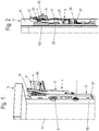
- This hook part 32 is used for hanging in a wall 6 attached to the counter bearing 6, as in the Figures 1 to 3 for example is shown.
- the counter bearing 6 is preferably designed as a horizontally mountable mounting rail 9 with an upper web 62 projecting from the wall 9, which is engaged behind by a free end 33 of the hook part 32 when the hook part 32 is in the suspended state.
- a central region 61 of the counterbearing 6 is provided with a multiplicity of perforations 65 which serve to receive fastening means 63 with which the counterbearing 6 can be fixed on the wall 9.
- a web 64 projecting perpendicularly from the wall 9 can optionally be formed.
- a securing element 4 is provided on the support element 3, preferably designed as a spring plate element.
- securing element 4 is preferably fixed to the supporting element 3 with the aid of a rivet 48 which extends through a bore 42 in a contact surface 41 of the securing element 4 and a bore 36 above the elongated hole 35 of the supporting element 3.
- the securing element 4 extends vertically upwards into an area between the hook part 32 and the base body 31 of the support element 3, as shown in FIG Figure 4 is shown.
- the securing element 4 is frictionally pressed against the counter bearing 6.
- two corner regions are bent toward claw-like cutting edges 46 towards the hook part 32, which in the suspended state of the hook part 32 are pressed into the counter bearing 6 and a surface 65 of the counter bearing 6.
- the cutting edge 46 is produced by a stamping process and forms, as in FIG Figure 11 shown, a wedge angle, which is less than or equal to 90 ° degrees.
- the securing element 4 has at least one pressure surface 43, 44 oriented at an angle to the contact surface 41.
- the contact surface 41 and the at least one pressure surface 43, 44 are arranged one behind the other in the direction of the longitudinal axis of the support element 3.
- the hanging process of the furniture on the counter bearing 6 is in the Figures 8a to 8d ).
- Figure 8a shows the furniture with the hanging device 1 attached to it before hanging on the counter bearing 6.
- the hook part 32 with the hook-shaped end 33 in the form of two angled teeth is positioned above the web 62 of the counter bearing 6 projecting from the wall 9.
- the web 62 already touches a second contact surface 44 of the securing element 4.
- the second contact surface 44 is oriented at an angle to a first contact surface 43 of the securing element 4, which in turn is angled relative to the contact surface 41.
- the contact surface 41 of the securing element 4 lies against the base body 31 of the supporting element 3.
- the spring arm which is largely responsible for the spring force acting is up to the second contact surface 44 on which the web 62 of the counter bearing 6 in Figure 8b ) pressed against, still relatively large and therefore comparatively easy to push in.
- a tongue 47 is formed on the securing element 4 and extends in the direction of the housing 2 into an opening 38 in a surface 37 of the base body 31 of the support element 3 that is offset towards the housing 2.
- This tongue 47 is preferably punched out of the material of the securing element 4 and bent in the direction of the housing 2.
- Figures 10a) and 10b ) show the two adjustment options of the suspension device 1 for adjusting the furniture 5 in the vertical direction and for adjusting the distance of the rear wall 52 of the furniture 5 from the wall 9 with the aid of tools 10, for example screwdrivers, which can be accessed through respective adjustment openings in the rear wall of the furniture 5 enable on the adjusting bolt 8 or the pinion 7.
Landscapes
- Supports Or Holders For Household Use (AREA)
- Connection Of Plates (AREA)
Claims (8)
- Dispositif de suspension (1) pour suspendre un meuble (5) à un mur (9), comprenant- un contre-palier (6) fixé à un mur- un logement (2) qui peut être fixé à une paroi du meuble (5),- un élément de support (3) disposé sur le logement (2),dans lequel l'élément de support (3) comporte une partie en forme de crochet (32) qui peut être suspendue au contre-palier (6),- un élément de fixation (4) fixé à l'élément de support (3) pour empêcher le détachement involontaire de l'élément de support (3) de le contre-palier (6),- dans lequel l'élément de fixation (4) s'étend dans une zone entre la partie crochet (32) et un corps de base (31) de l'élément de support (3) et forme une liaison par friction avec le contre-palier (6) lorsque la partie crochet (32) est à l'état suspendu,
caractérisé en ce que- l'élément de fixation (4) présente au moins une arête de coupe (46) qui, lorsque la partie crochet (32) est fixée au contre-palier (6), est enfoncée dans une surface (65) du contre-palier (6) et forme ainsi une liaison positive. - Dispositif de suspension selon la revendication 1, caractérisé en ce que l'élément de fixation (4) est un élément de plaque à ressort.
- Dispositif de suspension (1) selon la revendication 1 ou 2, caractérisé en ce que sur un bord supérieur (45) de l'élément de fixation (4), qui est réalisé sous forme d'élément en tôle élastique (4), positionné dans la zone entre la partie formant crochet (32) et le corps de base (31) de l'élément de support (3), deux zones d'angle sont repliées vers la partie formant crochet (32) pour former des arêtes de coupe (46) en forme de griffes.
- Dispositif de suspension (1) selon l'une des revendications ci-dessus, caractérisé en ce que l'élément de fixation (4) est fixé de manière non détachable, en particulier riveté, à l'élément de support (3) dans la zone d'une surface de contact (41).
- Dispositif de suspension (1) selon l'une des revendications ci-dessus, caractérisé en ce que l'élément de fixation (4) présente au moins une surface de pression (43, 44) orientée sous un angle par rapport à la surface de contact (41), la surface de contact (41) et la au moins une surface de pression (43, 44) étant disposées l'une derrière l'autre dans la direction de l'axe longitudinal de l'élément de support (3).
- Dispositif de suspension (1) selon l'une des revendications ci-dessus, caractérisé en ce que l'élément de fixation (4) est fixé à l'élément de support (3) de manière à ne pas pouvoir tourner.
- Dispositif de suspension (1) selon la revendication 6, caractérisé en ce qu'une languette (47) s'étendant en direction du logement (2) dans une ouverture (38) du corps de base (31) de l'élément de support (3) est formée sur l'élément de fixation (4).
- Utilisation d'un dispositif de suspension (1) conformément à l'une des revendications ci-dessus pour suspendre un meuble (5), en particulier un meuble suspendu qui peut être suspendu, à un contre-palier (6) disposé sur un mur (9).
Applications Claiming Priority (1)
| Application Number | Priority Date | Filing Date | Title |
|---|---|---|---|
| DE102017108117.8A DE102017108117A1 (de) | 2017-04-13 | 2017-04-13 | Aufhängevorrichtung zur Aufhängung eines Möbels an einer Wand und Verwendung einer solchen Aufhängevorrichtung |
Publications (2)
| Publication Number | Publication Date |
|---|---|
| EP3387954A1 EP3387954A1 (fr) | 2018-10-17 |
| EP3387954B1 true EP3387954B1 (fr) | 2020-05-13 |
Family
ID=61899101
Family Applications (1)
| Application Number | Title | Priority Date | Filing Date |
|---|---|---|---|
| EP18165586.1A Active EP3387954B1 (fr) | 2017-04-13 | 2018-04-04 | Dispositif de suspension pour suspendre un meuble sur un mur et utilisation d'un tel dispositif de suspension |
Country Status (3)
| Country | Link |
|---|---|
| EP (1) | EP3387954B1 (fr) |
| DE (1) | DE102017108117A1 (fr) |
| ES (1) | ES2805838T3 (fr) |
Families Citing this family (3)
| Publication number | Priority date | Publication date | Assignee | Title |
|---|---|---|---|---|
| DE102021130425A1 (de) | 2021-11-22 | 2023-05-25 | Viessmann Climate Solutions Se | Befestigungsvorrichtung |
| DE102023127821A1 (de) * | 2023-10-11 | 2025-04-17 | Hettich-Heinze Gmbh & Co. Kg | Aufhängevorrichtung |
| DE102024118749A1 (de) * | 2024-07-02 | 2026-01-08 | Nobilia-Werke J. Stickling GmbH & Co. KG | Aufhängesystem und Verfahren zur Montage eines Möbels |
Family Cites Families (3)
| Publication number | Priority date | Publication date | Assignee | Title |
|---|---|---|---|---|
| US4601247A (en) * | 1984-08-15 | 1986-07-22 | Modular Systems, Inc. | Resilient fastener clip and joint therefor |
| DE9201572U1 (de) * | 1992-02-08 | 1993-03-18 | Paul Hettich GmbH & Co, 4983 Kirchlengern | Aufhängevorrichtung für Möbel |
| DE202012012377U1 (de) | 2012-12-20 | 2014-03-21 | Hetal-Werke Franz Hettich Gmbh & Co. Kg | Aufhängevorrichtung für Möbel |
-
2017
- 2017-04-13 DE DE102017108117.8A patent/DE102017108117A1/de not_active Withdrawn
-
2018
- 2018-04-04 EP EP18165586.1A patent/EP3387954B1/fr active Active
- 2018-04-04 ES ES18165586T patent/ES2805838T3/es active Active
Non-Patent Citations (1)
| Title |
|---|
| None * |
Also Published As
| Publication number | Publication date |
|---|---|
| DE102017108117A1 (de) | 2018-10-18 |
| EP3387954A1 (fr) | 2018-10-17 |
| ES2805838T3 (es) | 2021-02-15 |
Similar Documents
| Publication | Publication Date | Title |
|---|---|---|
| EP3082508B1 (fr) | Élément de paroi de tiroir | |
| DE202008018315U1 (de) | Fahrzeugsitzgleitvorrichtung | |
| DE20218574U1 (de) | Trägersystem für Regalelemente | |
| EP3289925B1 (fr) | Support d'angle | |
| EP3111801B1 (fr) | Dispositif porteur pour meuble | |
| AT510776B1 (de) | Behältnisschiene | |
| EP2642889A1 (fr) | Paroi latérale de tiroir présentant une paroi intérieure et une paroi extérieure | |
| EP3387954A1 (fr) | Dispositif de suspension pour suspendre un meuble sur un mur et utilisation d'un tel dispositif de suspension | |
| EP3652400B1 (fr) | Dispositif pour animer une partie de meuble d'un mouvement et meuble | |
| DE202010000173U1 (de) | Halteelement mit einem Gleiter für Gardinenleisten | |
| DE3012261C2 (de) | Aufhängevorrichtung für eine Tragschiene einer Unterdecke | |
| AT13864U1 (de) | Tragvorrichtung für eine Betonschalung | |
| EP0886708B1 (fr) | Systeme d'ancrage pour panneaux de fa ade | |
| EP0539672A1 (fr) | Ferrure pour fixation dans une rainure d'un profilé rétréci des deux côtés | |
| EP3387953B1 (fr) | Dispositif de suspension pour suspendre un meuble sur un mur et utilisation d'un tel dispositif de suspension | |
| DE202004012107U1 (de) | Ausrichtvorrichtung und/oder Aufhängevorrichtungssystem | |
| EP2233039B1 (fr) | Guidage pour tiroirs | |
| DE102010006726B4 (de) | Beschlagsystem zur wandhängenden Montage von Möbelkorpussen | |
| EP3093420B1 (fr) | Dispositif de fixation de portes | |
| EP0984126B1 (fr) | Dispositif de guidage pour une porte coulissante | |
| EP3757464A1 (fr) | Boîtier à suspendre au mur | |
| EP1203865A1 (fr) | Volet roulant | |
| EP4537708B1 (fr) | Dispositif de suspension | |
| EP3231954A1 (fr) | Suspente réglable en longueur pour l'ancrage d'une sous-structure suspendue | |
| EP4537707B1 (fr) | Dispositif de suspension |
Legal Events
| Date | Code | Title | Description |
|---|---|---|---|
| PUAI | Public reference made under article 153(3) epc to a published international application that has entered the european phase |
Free format text: ORIGINAL CODE: 0009012 |
|
| STAA | Information on the status of an ep patent application or granted ep patent |
Free format text: STATUS: THE APPLICATION HAS BEEN PUBLISHED |
|
| AK | Designated contracting states |
Kind code of ref document: A1 Designated state(s): AL AT BE BG CH CY CZ DE DK EE ES FI FR GB GR HR HU IE IS IT LI LT LU LV MC MK MT NL NO PL PT RO RS SE SI SK SM TR |
|
| AX | Request for extension of the european patent |
Extension state: BA ME |
|
| STAA | Information on the status of an ep patent application or granted ep patent |
Free format text: STATUS: REQUEST FOR EXAMINATION WAS MADE |
|
| 17P | Request for examination filed |
Effective date: 20190416 |
|
| RBV | Designated contracting states (corrected) |
Designated state(s): AL AT BE BG CH CY CZ DE DK EE ES FI FR GB GR HR HU IE IS IT LI LT LU LV MC MK MT NL NO PL PT RO RS SE SI SK SM TR |
|
| STAA | Information on the status of an ep patent application or granted ep patent |
Free format text: STATUS: EXAMINATION IS IN PROGRESS |
|
| 17Q | First examination report despatched |
Effective date: 20190716 |
|
| GRAP | Despatch of communication of intention to grant a patent |
Free format text: ORIGINAL CODE: EPIDOSNIGR1 |
|
| STAA | Information on the status of an ep patent application or granted ep patent |
Free format text: STATUS: GRANT OF PATENT IS INTENDED |
|
| INTG | Intention to grant announced |
Effective date: 20200225 |
|
| GRAS | Grant fee paid |
Free format text: ORIGINAL CODE: EPIDOSNIGR3 |
|
| GRAL | Information related to payment of fee for publishing/printing deleted |
Free format text: ORIGINAL CODE: EPIDOSDIGR3 |
|
| GRAS | Grant fee paid |
Free format text: ORIGINAL CODE: EPIDOSNIGR3 |
|
| GRAA | (expected) grant |
Free format text: ORIGINAL CODE: 0009210 |
|
| STAA | Information on the status of an ep patent application or granted ep patent |
Free format text: STATUS: THE PATENT HAS BEEN GRANTED |
|
| AK | Designated contracting states |
Kind code of ref document: B1 Designated state(s): AL AT BE BG CH CY CZ DE DK EE ES FI FR GB GR HR HU IE IS IT LI LT LU LV MC MK MT NL NO PL PT RO RS SE SI SK SM TR |
|
| REG | Reference to a national code |
Ref country code: GB Ref legal event code: FG4D Free format text: NOT ENGLISH |
|
| REG | Reference to a national code |
Ref country code: CH Ref legal event code: EP |
|
| REG | Reference to a national code |
Ref country code: DE Ref legal event code: R096 Ref document number: 502018001396 Country of ref document: DE |
|
| REG | Reference to a national code |
Ref country code: AT Ref legal event code: REF Ref document number: 1269082 Country of ref document: AT Kind code of ref document: T Effective date: 20200615 |
|
| REG | Reference to a national code |
Ref country code: LT Ref legal event code: MG4D |
|
| REG | Reference to a national code |
Ref country code: NL Ref legal event code: MP Effective date: 20200513 |
|
| PG25 | Lapsed in a contracting state [announced via postgrant information from national office to epo] |
Ref country code: IS Free format text: LAPSE BECAUSE OF FAILURE TO SUBMIT A TRANSLATION OF THE DESCRIPTION OR TO PAY THE FEE WITHIN THE PRESCRIBED TIME-LIMIT Effective date: 20200913 Ref country code: SE Free format text: LAPSE BECAUSE OF FAILURE TO SUBMIT A TRANSLATION OF THE DESCRIPTION OR TO PAY THE FEE WITHIN THE PRESCRIBED TIME-LIMIT Effective date: 20200513 Ref country code: FI Free format text: LAPSE BECAUSE OF FAILURE TO SUBMIT A TRANSLATION OF THE DESCRIPTION OR TO PAY THE FEE WITHIN THE PRESCRIBED TIME-LIMIT Effective date: 20200513 Ref country code: GR Free format text: LAPSE BECAUSE OF FAILURE TO SUBMIT A TRANSLATION OF THE DESCRIPTION OR TO PAY THE FEE WITHIN THE PRESCRIBED TIME-LIMIT Effective date: 20200814 Ref country code: NO Free format text: LAPSE BECAUSE OF FAILURE TO SUBMIT A TRANSLATION OF THE DESCRIPTION OR TO PAY THE FEE WITHIN THE PRESCRIBED TIME-LIMIT Effective date: 20200813 Ref country code: PT Free format text: LAPSE BECAUSE OF FAILURE TO SUBMIT A TRANSLATION OF THE DESCRIPTION OR TO PAY THE FEE WITHIN THE PRESCRIBED TIME-LIMIT Effective date: 20200914 Ref country code: LT Free format text: LAPSE BECAUSE OF FAILURE TO SUBMIT A TRANSLATION OF THE DESCRIPTION OR TO PAY THE FEE WITHIN THE PRESCRIBED TIME-LIMIT Effective date: 20200513 |
|
| PG25 | Lapsed in a contracting state [announced via postgrant information from national office to epo] |
Ref country code: LV Free format text: LAPSE BECAUSE OF FAILURE TO SUBMIT A TRANSLATION OF THE DESCRIPTION OR TO PAY THE FEE WITHIN THE PRESCRIBED TIME-LIMIT Effective date: 20200513 Ref country code: RS Free format text: LAPSE BECAUSE OF FAILURE TO SUBMIT A TRANSLATION OF THE DESCRIPTION OR TO PAY THE FEE WITHIN THE PRESCRIBED TIME-LIMIT Effective date: 20200513 Ref country code: BG Free format text: LAPSE BECAUSE OF FAILURE TO SUBMIT A TRANSLATION OF THE DESCRIPTION OR TO PAY THE FEE WITHIN THE PRESCRIBED TIME-LIMIT Effective date: 20200813 Ref country code: HR Free format text: LAPSE BECAUSE OF FAILURE TO SUBMIT A TRANSLATION OF THE DESCRIPTION OR TO PAY THE FEE WITHIN THE PRESCRIBED TIME-LIMIT Effective date: 20200513 |
|
| PG25 | Lapsed in a contracting state [announced via postgrant information from national office to epo] |
Ref country code: NL Free format text: LAPSE BECAUSE OF FAILURE TO SUBMIT A TRANSLATION OF THE DESCRIPTION OR TO PAY THE FEE WITHIN THE PRESCRIBED TIME-LIMIT Effective date: 20200513 Ref country code: AL Free format text: LAPSE BECAUSE OF FAILURE TO SUBMIT A TRANSLATION OF THE DESCRIPTION OR TO PAY THE FEE WITHIN THE PRESCRIBED TIME-LIMIT Effective date: 20200513 |
|
| PG25 | Lapsed in a contracting state [announced via postgrant information from national office to epo] |
Ref country code: RO Free format text: LAPSE BECAUSE OF FAILURE TO SUBMIT A TRANSLATION OF THE DESCRIPTION OR TO PAY THE FEE WITHIN THE PRESCRIBED TIME-LIMIT Effective date: 20200513 Ref country code: SM Free format text: LAPSE BECAUSE OF FAILURE TO SUBMIT A TRANSLATION OF THE DESCRIPTION OR TO PAY THE FEE WITHIN THE PRESCRIBED TIME-LIMIT Effective date: 20200513 Ref country code: EE Free format text: LAPSE BECAUSE OF FAILURE TO SUBMIT A TRANSLATION OF THE DESCRIPTION OR TO PAY THE FEE WITHIN THE PRESCRIBED TIME-LIMIT Effective date: 20200513 Ref country code: DK Free format text: LAPSE BECAUSE OF FAILURE TO SUBMIT A TRANSLATION OF THE DESCRIPTION OR TO PAY THE FEE WITHIN THE PRESCRIBED TIME-LIMIT Effective date: 20200513 Ref country code: CZ Free format text: LAPSE BECAUSE OF FAILURE TO SUBMIT A TRANSLATION OF THE DESCRIPTION OR TO PAY THE FEE WITHIN THE PRESCRIBED TIME-LIMIT Effective date: 20200513 |
|
| REG | Reference to a national code |
Ref country code: ES Ref legal event code: FG2A Ref document number: 2805838 Country of ref document: ES Kind code of ref document: T3 Effective date: 20210215 |
|
| REG | Reference to a national code |
Ref country code: DE Ref legal event code: R097 Ref document number: 502018001396 Country of ref document: DE |
|
| PG25 | Lapsed in a contracting state [announced via postgrant information from national office to epo] |
Ref country code: SK Free format text: LAPSE BECAUSE OF FAILURE TO SUBMIT A TRANSLATION OF THE DESCRIPTION OR TO PAY THE FEE WITHIN THE PRESCRIBED TIME-LIMIT Effective date: 20200513 Ref country code: PL Free format text: LAPSE BECAUSE OF FAILURE TO SUBMIT A TRANSLATION OF THE DESCRIPTION OR TO PAY THE FEE WITHIN THE PRESCRIBED TIME-LIMIT Effective date: 20200513 |
|
| PLBE | No opposition filed within time limit |
Free format text: ORIGINAL CODE: 0009261 |
|
| STAA | Information on the status of an ep patent application or granted ep patent |
Free format text: STATUS: NO OPPOSITION FILED WITHIN TIME LIMIT |
|
| 26N | No opposition filed |
Effective date: 20210216 |
|
| PG25 | Lapsed in a contracting state [announced via postgrant information from national office to epo] |
Ref country code: SI Free format text: LAPSE BECAUSE OF FAILURE TO SUBMIT A TRANSLATION OF THE DESCRIPTION OR TO PAY THE FEE WITHIN THE PRESCRIBED TIME-LIMIT Effective date: 20200513 |
|
| PG25 | Lapsed in a contracting state [announced via postgrant information from national office to epo] |
Ref country code: MC Free format text: LAPSE BECAUSE OF FAILURE TO SUBMIT A TRANSLATION OF THE DESCRIPTION OR TO PAY THE FEE WITHIN THE PRESCRIBED TIME-LIMIT Effective date: 20200513 |
|
| PG25 | Lapsed in a contracting state [announced via postgrant information from national office to epo] |
Ref country code: LU Free format text: LAPSE BECAUSE OF NON-PAYMENT OF DUE FEES Effective date: 20210404 |
|
| REG | Reference to a national code |
Ref country code: BE Ref legal event code: MM Effective date: 20210430 |
|
| PG25 | Lapsed in a contracting state [announced via postgrant information from national office to epo] |
Ref country code: FR Free format text: LAPSE BECAUSE OF NON-PAYMENT OF DUE FEES Effective date: 20210430 Ref country code: LI Free format text: LAPSE BECAUSE OF NON-PAYMENT OF DUE FEES Effective date: 20210430 Ref country code: CH Free format text: LAPSE BECAUSE OF NON-PAYMENT OF DUE FEES Effective date: 20210430 |
|
| PG25 | Lapsed in a contracting state [announced via postgrant information from national office to epo] |
Ref country code: IE Free format text: LAPSE BECAUSE OF NON-PAYMENT OF DUE FEES Effective date: 20210404 |
|
| PG25 | Lapsed in a contracting state [announced via postgrant information from national office to epo] |
Ref country code: BE Free format text: LAPSE BECAUSE OF NON-PAYMENT OF DUE FEES Effective date: 20210430 |
|
| GBPC | Gb: european patent ceased through non-payment of renewal fee |
Effective date: 20220404 |
|
| PG25 | Lapsed in a contracting state [announced via postgrant information from national office to epo] |
Ref country code: GB Free format text: LAPSE BECAUSE OF NON-PAYMENT OF DUE FEES Effective date: 20220404 |
|
| P01 | Opt-out of the competence of the unified patent court (upc) registered |
Effective date: 20230415 |
|
| PG25 | Lapsed in a contracting state [announced via postgrant information from national office to epo] |
Ref country code: CY Free format text: LAPSE BECAUSE OF FAILURE TO SUBMIT A TRANSLATION OF THE DESCRIPTION OR TO PAY THE FEE WITHIN THE PRESCRIBED TIME-LIMIT Effective date: 20200513 |
|
| PG25 | Lapsed in a contracting state [announced via postgrant information from national office to epo] |
Ref country code: HU Free format text: LAPSE BECAUSE OF FAILURE TO SUBMIT A TRANSLATION OF THE DESCRIPTION OR TO PAY THE FEE WITHIN THE PRESCRIBED TIME-LIMIT; INVALID AB INITIO Effective date: 20180404 |
|
| PG25 | Lapsed in a contracting state [announced via postgrant information from national office to epo] |
Ref country code: MK Free format text: LAPSE BECAUSE OF FAILURE TO SUBMIT A TRANSLATION OF THE DESCRIPTION OR TO PAY THE FEE WITHIN THE PRESCRIBED TIME-LIMIT Effective date: 20200513 |
|
| REG | Reference to a national code |
Ref country code: AT Ref legal event code: MM01 Ref document number: 1269082 Country of ref document: AT Kind code of ref document: T Effective date: 20230404 |
|
| PG25 | Lapsed in a contracting state [announced via postgrant information from national office to epo] |
Ref country code: TR Free format text: LAPSE BECAUSE OF FAILURE TO SUBMIT A TRANSLATION OF THE DESCRIPTION OR TO PAY THE FEE WITHIN THE PRESCRIBED TIME-LIMIT Effective date: 20200513 |
|
| PG25 | Lapsed in a contracting state [announced via postgrant information from national office to epo] |
Ref country code: AT Free format text: LAPSE BECAUSE OF NON-PAYMENT OF DUE FEES Effective date: 20230404 |
|
| PG25 | Lapsed in a contracting state [announced via postgrant information from national office to epo] |
Ref country code: AT Free format text: LAPSE BECAUSE OF NON-PAYMENT OF DUE FEES Effective date: 20230404 |
|
| PG25 | Lapsed in a contracting state [announced via postgrant information from national office to epo] |
Ref country code: MT Free format text: LAPSE BECAUSE OF FAILURE TO SUBMIT A TRANSLATION OF THE DESCRIPTION OR TO PAY THE FEE WITHIN THE PRESCRIBED TIME-LIMIT Effective date: 20200513 |
|
| PGFP | Annual fee paid to national office [announced via postgrant information from national office to epo] |
Ref country code: DE Payment date: 20250417 Year of fee payment: 8 |
|
| PGFP | Annual fee paid to national office [announced via postgrant information from national office to epo] |
Ref country code: ES Payment date: 20250519 Year of fee payment: 8 |
|
| PGFP | Annual fee paid to national office [announced via postgrant information from national office to epo] |
Ref country code: IT Payment date: 20250430 Year of fee payment: 8 |
|
| PGFP | Annual fee paid to national office [announced via postgrant information from national office to epo] |
Ref country code: AT Payment date: 20260410 Year of fee payment: 5 |