EP3388104A1 - Schlauchleitung und verfahren zu deren herstellung - Google Patents
Schlauchleitung und verfahren zu deren herstellung Download PDFInfo
- Publication number
- EP3388104A1 EP3388104A1 EP18165761.0A EP18165761A EP3388104A1 EP 3388104 A1 EP3388104 A1 EP 3388104A1 EP 18165761 A EP18165761 A EP 18165761A EP 3388104 A1 EP3388104 A1 EP 3388104A1
- Authority
- EP
- European Patent Office
- Prior art keywords
- hose
- jacket
- fluid
- line
- radial passage
- Prior art date
- Legal status (The legal status is an assumption and is not a legal conclusion. Google has not performed a legal analysis and makes no representation as to the accuracy of the status listed.)
- Granted
Links
Images


Classifications
-
- A—HUMAN NECESSITIES
- A61—MEDICAL OR VETERINARY SCIENCE; HYGIENE
- A61M—DEVICES FOR INTRODUCING MEDIA INTO, OR ONTO, THE BODY; DEVICES FOR TRANSDUCING BODY MEDIA OR FOR TAKING MEDIA FROM THE BODY; DEVICES FOR PRODUCING OR ENDING SLEEP OR STUPOR
- A61M25/00—Catheters; Hollow probes
- A61M25/0009—Making of catheters or other medical or surgical tubes
- A61M25/0013—Weakening parts of a catheter tubing, e.g. by making cuts in the tube or reducing thickness of a layer at one point to adjust the flexibility
-
- A—HUMAN NECESSITIES
- A61—MEDICAL OR VETERINARY SCIENCE; HYGIENE
- A61M—DEVICES FOR INTRODUCING MEDIA INTO, OR ONTO, THE BODY; DEVICES FOR TRANSDUCING BODY MEDIA OR FOR TAKING MEDIA FROM THE BODY; DEVICES FOR PRODUCING OR ENDING SLEEP OR STUPOR
- A61M25/00—Catheters; Hollow probes
- A61M25/0009—Making of catheters or other medical or surgical tubes
- A61M25/0015—Making lateral openings in a catheter tube, e.g. holes, slits, ports, piercings of guidewire ports; Methods for processing the holes, e.g. smoothing the edges
-
- A—HUMAN NECESSITIES
- A61—MEDICAL OR VETERINARY SCIENCE; HYGIENE
- A61M—DEVICES FOR INTRODUCING MEDIA INTO, OR ONTO, THE BODY; DEVICES FOR TRANSDUCING BODY MEDIA OR FOR TAKING MEDIA FROM THE BODY; DEVICES FOR PRODUCING OR ENDING SLEEP OR STUPOR
- A61M25/00—Catheters; Hollow probes
- A61M25/0021—Catheters; Hollow probes characterised by the form of the tubing
- A61M25/0023—Catheters; Hollow probes characterised by the form of the tubing by the form of the lumen, e.g. cross-section, variable diameter
- A61M25/0026—Multi-lumen catheters with stationary elements
- A61M25/0029—Multi-lumen catheters with stationary elements characterized by features relating to least one lumen located at the middle part of the catheter, e.g. slots, flaps, valves, cuffs, apertures, notches, grooves or rapid exchange ports
-
- A—HUMAN NECESSITIES
- A61—MEDICAL OR VETERINARY SCIENCE; HYGIENE
- A61M—DEVICES FOR INTRODUCING MEDIA INTO, OR ONTO, THE BODY; DEVICES FOR TRANSDUCING BODY MEDIA OR FOR TAKING MEDIA FROM THE BODY; DEVICES FOR PRODUCING OR ENDING SLEEP OR STUPOR
- A61M25/00—Catheters; Hollow probes
- A61M25/0021—Catheters; Hollow probes characterised by the form of the tubing
- A61M25/0023—Catheters; Hollow probes characterised by the form of the tubing by the form of the lumen, e.g. cross-section, variable diameter
- A61M25/0026—Multi-lumen catheters with stationary elements
- A61M25/003—Multi-lumen catheters with stationary elements characterized by features relating to least one lumen located at the distal part of the catheter, e.g. filters, plugs or valves
-
- A—HUMAN NECESSITIES
- A61—MEDICAL OR VETERINARY SCIENCE; HYGIENE
- A61M—DEVICES FOR INTRODUCING MEDIA INTO, OR ONTO, THE BODY; DEVICES FOR TRANSDUCING BODY MEDIA OR FOR TAKING MEDIA FROM THE BODY; DEVICES FOR PRODUCING OR ENDING SLEEP OR STUPOR
- A61M25/00—Catheters; Hollow probes
- A61M25/0067—Catheters; Hollow probes characterised by the distal end, e.g. tips
- A61M25/0068—Static characteristics of the catheter tip, e.g. shape, atraumatic tip, curved tip or tip structure
- A61M25/007—Side holes, e.g. their profiles or arrangements; Provisions to keep side holes unblocked
-
- B—PERFORMING OPERATIONS; TRANSPORTING
- B23—MACHINE TOOLS; METAL-WORKING NOT OTHERWISE PROVIDED FOR
- B23K—SOLDERING OR UNSOLDERING; WELDING; CLADDING OR PLATING BY SOLDERING OR WELDING; CUTTING BY APPLYING HEAT LOCALLY, e.g. FLAME CUTTING; WORKING BY LASER BEAM
- B23K26/00—Working by laser beam, e.g. welding, cutting or boring
- B23K26/20—Bonding
- B23K26/21—Bonding by welding
- B23K26/24—Seam welding
-
- B—PERFORMING OPERATIONS; TRANSPORTING
- B23—MACHINE TOOLS; METAL-WORKING NOT OTHERWISE PROVIDED FOR
- B23K—SOLDERING OR UNSOLDERING; WELDING; CLADDING OR PLATING BY SOLDERING OR WELDING; CUTTING BY APPLYING HEAT LOCALLY, e.g. FLAME CUTTING; WORKING BY LASER BEAM
- B23K26/00—Working by laser beam, e.g. welding, cutting or boring
- B23K26/36—Removing material
- B23K26/38—Removing material by boring or cutting
-
- F—MECHANICAL ENGINEERING; LIGHTING; HEATING; WEAPONS; BLASTING
- F16—ENGINEERING ELEMENTS AND UNITS; GENERAL MEASURES FOR PRODUCING AND MAINTAINING EFFECTIVE FUNCTIONING OF MACHINES OR INSTALLATIONS; THERMAL INSULATION IN GENERAL
- F16L—PIPES; JOINTS OR FITTINGS FOR PIPES; SUPPORTS FOR PIPES, CABLES OR PROTECTIVE TUBING; MEANS FOR THERMAL INSULATION IN GENERAL
- F16L11/00—Hoses, i.e. flexible pipes
- F16L11/20—Double-walled hoses
-
- F—MECHANICAL ENGINEERING; LIGHTING; HEATING; WEAPONS; BLASTING
- F16—ENGINEERING ELEMENTS AND UNITS; GENERAL MEASURES FOR PRODUCING AND MAINTAINING EFFECTIVE FUNCTIONING OF MACHINES OR INSTALLATIONS; THERMAL INSULATION IN GENERAL
- F16L—PIPES; JOINTS OR FITTINGS FOR PIPES; SUPPORTS FOR PIPES, CABLES OR PROTECTIVE TUBING; MEANS FOR THERMAL INSULATION IN GENERAL
- F16L11/00—Hoses, i.e. flexible pipes
- F16L11/22—Multi-channel hoses
-
- A—HUMAN NECESSITIES
- A61—MEDICAL OR VETERINARY SCIENCE; HYGIENE
- A61M—DEVICES FOR INTRODUCING MEDIA INTO, OR ONTO, THE BODY; DEVICES FOR TRANSDUCING BODY MEDIA OR FOR TAKING MEDIA FROM THE BODY; DEVICES FOR PRODUCING OR ENDING SLEEP OR STUPOR
- A61M25/00—Catheters; Hollow probes
- A61M25/0021—Catheters; Hollow probes characterised by the form of the tubing
- A61M25/0023—Catheters; Hollow probes characterised by the form of the tubing by the form of the lumen, e.g. cross-section, variable diameter
- A61M25/0026—Multi-lumen catheters with stationary elements
- A61M25/003—Multi-lumen catheters with stationary elements characterized by features relating to least one lumen located at the distal part of the catheter, e.g. filters, plugs or valves
- A61M2025/0031—Multi-lumen catheters with stationary elements characterized by features relating to least one lumen located at the distal part of the catheter, e.g. filters, plugs or valves characterized by lumina for withdrawing or delivering, i.e. used for extracorporeal circuit treatment
-
- A—HUMAN NECESSITIES
- A61—MEDICAL OR VETERINARY SCIENCE; HYGIENE
- A61M—DEVICES FOR INTRODUCING MEDIA INTO, OR ONTO, THE BODY; DEVICES FOR TRANSDUCING BODY MEDIA OR FOR TAKING MEDIA FROM THE BODY; DEVICES FOR PRODUCING OR ENDING SLEEP OR STUPOR
- A61M25/00—Catheters; Hollow probes
- A61M25/0021—Catheters; Hollow probes characterised by the form of the tubing
- A61M25/0023—Catheters; Hollow probes characterised by the form of the tubing by the form of the lumen, e.g. cross-section, variable diameter
- A61M25/0026—Multi-lumen catheters with stationary elements
- A61M2025/0034—Multi-lumen catheters with stationary elements characterized by elements which are assembled, connected or fused, e.g. splittable tubes, outer sheaths creating lumina or separate cores
-
- A—HUMAN NECESSITIES
- A61—MEDICAL OR VETERINARY SCIENCE; HYGIENE
- A61M—DEVICES FOR INTRODUCING MEDIA INTO, OR ONTO, THE BODY; DEVICES FOR TRANSDUCING BODY MEDIA OR FOR TAKING MEDIA FROM THE BODY; DEVICES FOR PRODUCING OR ENDING SLEEP OR STUPOR
- A61M25/00—Catheters; Hollow probes
- A61M25/0021—Catheters; Hollow probes characterised by the form of the tubing
- A61M25/0023—Catheters; Hollow probes characterised by the form of the tubing by the form of the lumen, e.g. cross-section, variable diameter
- A61M25/0026—Multi-lumen catheters with stationary elements
- A61M2025/0037—Multi-lumen catheters with stationary elements characterized by lumina being arranged side-by-side
Definitions
- the known hose line has a radial passage, which branches off laterally from an axial passage, and a closure.
- the closure is arranged in the axial direction behind the radial passage in the axial passage and closes this fluid-tight.
- the radial passage is introduced by drilling or punching in the hose jacket of the hose.
- the closure is arranged in the form of a separate component or filling material in the axial passage.
- the object of the invention is to provide a hose assembly of the type mentioned, which is particularly advantageous to produce and ensures a functional seal.
- the at least one radial passage is formed by a substantially radially inwardly curved hose jacket section, which is partially separated from the rest of the hose jacket along a parting line, wherein the at least one closure is formed by the hose jacket portion on the inner surface of the jacket created and fluid-tight connected to this.
- the closure is formed by the hose jacket section which is sectionally separated from the remaining hose jacket along the dividing line, curved inwards, applied to the inner surface of the jacket and connected to it in a fluid-tight manner.
- the radial passage is formed as it were. Consequently, it is possible to dispense with a separate introduction of the radial passage, for example by means of punching or the like, and thus to save material.
- a sectional separation in the sense of the invention is to be understood that the hose casing portion is connected in any case along an edge region in one piece with the rest of the hose jacket.
- a radial passage in the sense of the invention is understood to mean an opening through which a fluid can flow out of the hose line and / or flow into the hose line, whereby a fluid flow from the axial passage to the radial passage and / or vice versa is made possible.
- the solution according to the invention is particularly advantageously suitable for catheter tubes, in particular for multi-lumen central venous catheters.
- the solution according to the invention can also be used in the field of general fluid technology, where lateral outlet openings on hose lines are relevant.
- the dividing line in a radially directed to the radial passage viewing direction on a tongue-shaped course.
- the course of the parting line comprises a first axially extending line section, a substantially semicircular line section and a third line section extending substantially in antiparallel and spaced apart from the first line section.
- the hose line is a medical catheter tube, in particular a central venous catheter, the first tube end a proximal catheter tube end, the second tube end a distal end of the catheter tube, the axial passage a first lumen and the radial passage of a Kathetestenbenkanal.
- a catheter tube which is particularly advantageously producible and functionally sealed is formed.
- At least a second lumen is provided which is fluid-tightly separated from the first lumen by an axially extending dividing wall, wherein the tubular casing section is connected in a fluid-tight manner to the dividing wall.
- the closure between the catheter septum and the distal end of the catheter tube is formed by means of a shaped cord or pasty molding compounds. This is complex and can lead to an incomplete seal due to the technology. Under certain circumstances, it may therefore come to a seed colonization and propagation in the field of closure. Infections can therefore not be excluded.
- This embodiment of the invention overcomes these disadvantages and provides a particularly advantageous multi-lumen catheter.
- the invention also relates to a method for producing a hose according to the above.
- the inventive method comprises the steps of: separating the hose jacket along the parting line; Buckling of the hose jacket section thus obtained in the radial direction and application of the hose jacket section to the jacket inner surface; fluid-tight connection of the hose casing section with the inner surface of the casing.
- the separation takes place by means of laser cutting.
- the geometry of the radial passage can be produced in a dimensionally accurate and accurate manner.
- the fluid-tight connection takes place by means of laser welding.
- a particularly reliable sealing can be achieved.
- the separation of the hose jacket by means of laser a particularly low-investment manufacturing can be achieved, since one and the same technology for the production of the radial opening and the production of the closure is applied.
- a generic hose 101 after Fig. 1 and 2 is intended in the field of fluid technology.
- the generic hose line 101 has a hose jacket 104, which is axially extended between a first hose end 102 and a second hose end 103 and has a jacket outer surface 105 and a jacket inner surface 106.
- the generic hose line 101 also has an axial passage 107 and a radial passage 108.
- the axial passage 107 is enclosed by the shell inner surface 106 and extends in the axial direction between the first hose end 102 and the second hose end 103.
- the radial passage 108 extends in the form of a circular cylindrical recess in the radial direction through the hose jacket 104 and thus forms a fluid-conducting connection of the axial passage 107 to the outer shell surface 105 of the hose 101.
- the generic hose 102 has a closure 109.
- the closure 109 is arranged in the axial direction between the radial passage 108 and the second tube end 103 and thus closes off the axial passage 107 on one side in the direction of the second tube end 103.
- the closure 109 is connected by a separate component fluid-tightly connected to the envelope inner surface 106 educated.
- the closure 109 may be formed by a plastic filling material or the like.
- the radial passage 108 is made in the known hose 109 by a complete separation of a hose sheath portion of the hose jacket 104 by means of punching, cutting or the like.
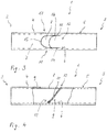
- a first embodiment of a hose line 1 according to the invention 3 and 4 is provided in the field of fluid technology for the radial outflow of a fluid.
- the hose line 1 according to the invention has a hose jacket 4, which is axially extended between a first hose end 2 and a second hose end 3 and has a jacket outer surface 5 and a jacket inner surface 6.
- Within the hose jacket 4 and enclosed by the shell inner surface 6 extends between the hose ends 2, 3, an axial passage 7.
- a radial passage 8 extends through the hose jacket 4, so that a fluid-conducting connection between the Axial trimlass 7 and the outer shell surface 5 is created.
- the radial passage 8 is formed by arching a section of hose jacket section 11 separate from the rest of the hose jacket 4 along a parting line 10.
- the hose casing section 11 is released from the remaining hose casing 4 along the dividing line in a manner which will be described in more detail below and connected in one end face 12 in one piece to the hose casing 4.
- the hose casing section 11 starting from the front end region 12, extends radially obliquely downwards to a wall section 13 of the casing inner surface 6 opposite the radial passage 8 and abuts against it.
- hose casing section 11 is connected in a fluid-tight manner to the wall section 13 of the casing inner surface 6 in a manner to be described in greater detail.
- a closure 9 is formed between the radial passage 8 and the second tube end 3, which closes the axial passage 7 in the direction of the second tube end 3 on one side.
- the separating line 10 has a first axially extending line section 14, a substantially semicircular second line section 15 and a third line section 16 extending substantially in antiparallel to the first line section 14. Such results in a tongue-shaped curve 17 of the dividing line 10th
- a second embodiment of the invention according to Fig. 5 is intended for use in the field of medical technology, in particular for use in infusion therapy.
- This embodiment has as a tubing a medical catheter tube 21, wherein the first tube end is a proximal catheter tube end 22, the second tube end is a distal catheter tube end 23, the axial passageway is a first lumen 24 and the radial passageway is a catheter tie channel 25.
- the catheter tube 21 also has a second lumen 26 extending between the proximal end of the catheter tube 22 and the distal end of the catheter tube 23 and into an exit opening 27 of a catheter Catheter tip 28 opens.
- the first lumen 24 and the second lumen 26 are fluid-tightly separated from one another by a substantially axially extending partition 29.
- a closure 30 in the form of a substantially radially inwardly curved tube sheath portion 31 of the catheter tube 21 is provided.
- the hose casing section 31 is along an unspecified and otherwise in an analogous manner to the parting line 10 of the first embodiment of the 3 and 4 on the outer shell surface N extending dividing line sections of the jacket M of the catheter tube 21 separately.
- the hose jacket section 31 is fluid-tightly connected in a fluid-tight manner to the dividing wall 29 and the adjacent jacket inner surface I of the catheter tube 21, or more precisely to the first lumen 24.
- the inventive method for producing a hose according to the preceding embodiments, first the hose jacket 4, 21 separated along a dividing line (A), the tube shell section 11, 31 thus obtained is arched in the radial direction (E) and applied to the shell inner surface (G) and then fluid-tightly connected thereto (V).
- the separation A is carried out by means of laser cutting and the fluid-tight connection V by means of laser welding
Landscapes
- Health & Medical Sciences (AREA)
- Life Sciences & Earth Sciences (AREA)
- Engineering & Computer Science (AREA)
- Biomedical Technology (AREA)
- Hematology (AREA)
- Veterinary Medicine (AREA)
- Public Health (AREA)
- Biophysics (AREA)
- Pulmonology (AREA)
- Anesthesiology (AREA)
- General Health & Medical Sciences (AREA)
- Heart & Thoracic Surgery (AREA)
- Animal Behavior & Ethology (AREA)
- Mechanical Engineering (AREA)
- General Engineering & Computer Science (AREA)
- Physics & Mathematics (AREA)
- Optics & Photonics (AREA)
- Plasma & Fusion (AREA)
- Rigid Pipes And Flexible Pipes (AREA)
- Infusion, Injection, And Reservoir Apparatuses (AREA)
- External Artificial Organs (AREA)
Abstract
Description
- Die Erfindung betrifft eine Schlauchleitung mit
- einem zwischen einem ersten Schlauchende und einem zweiten Schlauchende axial erstreckten Schlauchmantel mit einer Mantelaußenfläche und einer Mantelinnenfläche,
- mindestens einem von der Mantelinnenfläche umschlossenen und zwischen den Schlauchenden axial erstreckten Axialdurchlass,
- mindestens einem im Wesentlichen radial durch den Schlauchmantel erstreckten Radialdurchlass, der den mindestens einen Axialdurchlass fluidleitend mit der Mantelaußenfläche verbindet und
- mindestens einem zwischen dem Radialdurchlass und dem zweiten Schlauchende angeordneten und den mindestens einen Axialdurchlass in Richtung des zweiten Schlauchendes fluiddicht verschließenden Verschluss.
- Eine derartige Schlauchleitung ist im Bereich der Fluidtechnik allgemein bekannt und kann zum radialen Ausströmen eines Fluids verwendet werden. Zu diesem Zweck weist die bekannte Schlauchleitung einen Radialdurchlass, der seitlich von einem Axialdurchlass abzweigt, sowie einen Verschluss auf. Der Verschluss ist in axialer Richtung hinter dem Radialdurchlass in dem Axialdurchlass angeordnet und verschließt diesen fluiddicht. Der Radialdurchlass wird mittels Bohren oder Stanzen in den Schlauchmantel der Schlauchleitung eingebracht. Der Verschluss ist in Gestalt eines separaten Bauelements oder eines Füllmaterials in dem Axialdurchlass angeordnet.
- Aufgabe der Erfindung ist es, eine Schlauchleitung der eingangs genannten Art zu schaffen, die besonders vorteilhaft herstellbar ist und eine funktionsgerechte Abdichtung gewährleistet.
- Diese Aufgabe wird dadurch gelöst, dass der mindestens eine Radialdurchlass durch einen im Wesentlichen radial nach innen gewölbten Schlauchmantelabschnitt gebildet ist, der abschnittsweise von dem übrigen Schlauchmantel entlang einer Trennlinie getrennt ist, wobei der mindestens eine Verschluss dadurch gebildet ist, dass der Schlauchmantelabschnitt an der Mantelinnenfläche angelegt und fluiddicht mit dieser verbunden ist. Durch die erfindungsgemäße Lösung ist es möglich, auf ein zusätzliches Bauelement zum Verschließen des Axialdurchlasses zu verzichten. Stattdessen wird der Verschluss erfindungsgemäß durch den abschnittsweise von dem übrigen Schlauchmantel entlang der Trennlinie getrennten, nach innen gewölbten, an der Mantelinnenfläche angelegten und mit dieser fluiddicht verbundenen Schlauchmantelabschnitt gebildet. Durch die abschnittsweise Trennung von dem übrigen Schlauchmantel und die nach innen gerichtete Wölbung des Schlauchmantelabschnitts wird hierbei gleichsam der Radialdurchlass gebildet. Demzufolge kann auf eine gesonderte Einbringung des Radialdurchlasses, beispielsweise mittels Stanzen oder dergleichen, verzichtet und somit Material eingespart werden. Unter einer abschnittsweisen Trennung im Sinne der Erfindung ist zu verstehen, dass der Schlauchmantelabschnitt jedenfalls entlang eines Randbereichs einstückig mit dem übrigen Schlauchmantel verbunden ist. Unter einem Radialdurchlass im Sinne der Erfindung ist eine Öffnung zu verstehen, durch die ein Fluid aus der Schlauchleitung herausfließen und/oder in die Schlauchleitung hineinfließen kann, wodurch ein Fluidstrom vom axialen Durchlass zum radialen Durchlass und/oder umgekehrt ermöglicht ist.
- Die erfindungsgemäße Lösung eignet sich in besonders vorteilhafterweise für Katheterschläuche, insbesondere für mehrlumige Zentralvenenkatheter. Die Erfindungsgemäße Lösung kann aber auch im Bereich der allgemeinen Fluidtechnik, dort wo seitliche Austrittsöffnungen an Schlauchleitungen relevant sind, verwendet werden.
- In Ausgestaltung der Erfindung weist die Trennlinie in einer radial auf den Radialdurchlass gerichteter Blickrichtung einen zungenförmigen Verlauf auf. Der Verlauf der Trennlinie umfasst insoweit einen ersten axial verlaufenden Linienabschnitt, einen im Wesentlichen halbkreisförmigen Linienabschnitt und einen dritten im Wesentlichen antiparallel und zu dem ersten Linienabschnitt beabstandet verlaufenden Linienabschnitt. Durch diesen zungenförmigen Verlauf der Trennlinie kann eine besonders dichte Anlage und eine vorteilhafte Verbindung des Schlauchabschnitts mit der Mantelinnenfläche erreicht werden.
- In weiterer Ausgestaltung der Erfindung ist die Schlauchleitung ein medizinscher Katheterschlauch, insbesondere ein Zentralvenenkatheter, das erste Schlauchende ein proximales Katheterschlauchende, das zweite Schlauchende ein distales Katheterschlauchende, der Axialdurchlass ein erstes Lumen und der Radialdurchlass ein Katheternebenkanal. Auf diese Weise wird ein besonders vorteilhaft herstellbarer und funktionsgerecht abgedichteter Katheterschlauch gebildet.
- In weiterer Ausgestaltung der Erfindung ist zumindest ein zweites Lumen vorgesehen, das durch eine axial erstreckte Trennwand fluiddicht von dem ersten Lumen getrennt ist, wobei der Schlauchmantelabschnitt fluiddicht mit der Trennwand verbunden ist. Bei üblichen mehrlumigen Kathetern wird der Verschluss zwischen dem Katheternebenkanal und dem distalen Katheterschlauchende mittels Formschnur oder pastöser Formmassen gebildet. Dies ist aufwändig und kann technologiebedingt zu einer unvollständigen Abdichtung führen. Unter Umständen kann es deshalb zu einer Keimansiedlung und -vermehrung im Bereich des Verschlusses kommen. Infektionen können deshalb nicht ausgeschlossen werden. Diese Ausgestaltung der Erfindung behebt diese Nachteile und schafft einen besonders vorteilhaften mehrlumigen Katheter.
- Die Erfindung betrifft zudem ein Verfahren zur Herstellung einer Schlauchleitung gemäß den vorstehenden Ausführungen.
- Das erfindungsgemäße Verfahren umfasst die Schritte: Auftrennen des Schlauchmantels entlang der Trennlinie; Einwölben des derart erhaltenen Schlauchmantelabschnitts in radialer Richtung und Anlegen des Schlauchmantelabschnitts an der Mantelinnenfläche; fluiddichtes Verbinden des Schlauchmantelabschnitts mit der Mantelinnenfläche. Durch das erfindungsgemäße Verfahren kann der Verschluss ohne zusätzliche Bauelemente oder ein Verfüllen des Axialdurchlasses mit Formmasse geschaffen werden. Somit wird eine besonders kostengünstige Herstellung erreicht.
- In weiterer Ausgestaltung der Erfindung erfolgt das Auftrennen mittels Laserschneidens. Durch diese Ausgestaltung des erfindungsgemäßen Verfahrens kann die Geometrie des Radialdurchlasses besonders maßhaltig und qualitätsgetreu hergestellt werden.
- In weiterer Ausgestaltung der Erfindung erfolgt das fluiddichte Verbinden mittels Laserschweißens. Derart kann eine besonders zuverlässige Abdichtung erreicht werden. Sofern ebenfalls das Auftrennen des Schlauchmantels mittels Laser erfolgt, kann eine besonders investitionsarme Fertigung erreicht werden, da ein und dieselbe Technologie für die Herstellung der Radialöffnung und die Herstellung des Verschlusses Anwendung findet.
- Weitere Vorteile und Merkmale der Erfindung ergeben sich aus den Ansprüchen sowie aus der nachfolgenden Beschreibung bevorzugter Ausführungsbeispiele der Erfindung, die anhand der Zeichnungen dargestellt sind.
- Fig. 1
- zeigt in einer schematischen Draufsicht eine gattungsgemäße Schlauchleitung nach dem Stand der Technik,
- Fig. 2
- in einer teilweise geschnittenen Seitenansicht die gattungsgemäße Schlauchleitung nach
Fig. 1 , - Fig. 3
- in einer schematischen Draufsicht eine erste Ausführungsform einer erfindungsgemäßen Schlauchleitung,
- Fig. 4
- in einer teilweise geschnittenen Seitenansicht die Schlauchleitung nach
Fig. 3 , - Fig. 5
- in einer teilweise geschnittenen Seitenansicht eine zweite Ausführungsform einer erfindungsgemäßen Schlauchleitung, die im Bereich der Medizintechnik vorgesehen ist, und
- Fig. 6
- in einer schematischen Darstellung eine Ausführungsform des erfindungsgemäßen Verfahrens.
- Eine gattungsgemäße Schlauchleitung 101 nach
Fig. 1 und 2 ist im Bereich der Fluidtechnik vorgesehen. Die gattungsgemäße Schlauchleitung 101 weist einen zwischen einem ersten Schlauchende 102 und einem zweiten Schlauchende 103 axial erstreckten Schlauchmantel 104 mit einer Mantelaußenfläche 105 und einer Mantelinnenfläche 106 auf. Die gattungsgemäße Schlauchleitung 101 weist zudem einen Axialdurchlass 107 und einen Radialdurchlass 108 auf. Der Axialdurchlass 107 ist von der Mantelinnenfläche 106 umschlossen und erstreckt sich in axialer Richtung zwischen dem ersten Schlauchende 102 und dem zweiten Schlauchende 103. Der Radialdurchlass 108 erstreckt sich in Gestalt einer kreiszylindrischen Ausnehmung in radialer Richtung durch den Schlauchmantel 104 und bildet derart eine fluidleitende Verbindung von dem Axialdurchlass 107 zu der Mantelaußenfläche 105 der Schlauchleitung 101. Weiter weist die gattungsgemäße Schlauchleitung 102 einen Verschluss 109 auf. Der Verschluss 109 ist in axialer Richtung zwischen dem Radialdurchlass 108 und dem zweiten Schlauchende 103 angeordnet und verschließt derart den Axialdurchlass 107 einseitig in Richtung des zweiten Schlauchendes 103. Bei der gattungsgemäßen Schlauchleitung 101 ist der Verschluss 109 durch ein separates mit der Mantelinnenfläche 106 fluiddicht verbundenes Bauelement gebildet. Alternativ kann der Verschluss 109 durch eine plastische Füllmasse oder dergleichen gebildet sein. Der Radialdurchlass 108 ist bei der bekannten Schlauchleitung 109 durch ein vollständiges Heraustrennen eines Schlauchmantelabschnitts aus dem Schlauchmantel 104 mittels Stanzen, Schneiden oder dergleichen hergestellt. - Eine erste Ausführungsform einer erfindungsgemäßen Schlauchleitung 1 nach den
Fig. 3 und 4 ist im Bereich der Fluidtechnik zum radialen Ausströmen eines Fluids vorgesehen. Die erfindungsgemäße Schlauchleitung 1 weist einen zwischen einem ersten Schlauchende 2 und einem zweiten Schlauchende 3 axial erstreckten Schlauchmantel 4 mit einer Mantelaußenfläche 5 und einer Mantelinnenfläche 6 auf. Innerhalb des Schlauchmantels 4 und von der Mantelinnenfläche 6 umschlossen erstreckt sich zwischen den Schlauchenden 2, 3 ein Axialdurchlass 7. Von dem Axialdurchlass 7 im Wesentlichen in radialer Richtung abzweigend erstreckt sich ein Radialdurchlass 8 durch den Schlauchmantel 4, so dass eine fluidleitende Verbindung zwischen dem Axialdurchlass 7 und der Mantelaußenfläche 5 geschaffen ist. Der Radialdurchlass 8 ist durch Einwölben eines abschnittsweise von dem übrigen Schlauchmantel 4 entlang einer Trennlinie 10 getrennten Schlauchmantelabschnitts 11 gebildet. Der Schlauchmantelabschnitt 11 ist auf eine noch näher zu beschreibende Art und Weise entlang der Trennlinie von dem übrigen Schlauchmantel 4 gelöst und in einem Stirnendbereich 12 einstückig mit dem Schlauchmantel 4 verbunden. Wie anhand der teilweise geschnittenen Seitenansicht nachFig. 4 ersichtlich ist, erstreckt sich der Schlauchmantelabschnitt 11 ausgehend von dem Stirnendbereich 12 radial schräg nach unten gerichtet bis zu einem dem Radialdurchlass 8 gegenüberliegenden Wandabschnitt 13 der Mantelinnenfläche 6 und liegt an dieser an. Zudem ist der Schlauchmantelabschnitt 11 auf eine noch näher zu beschreibende Art und Weise fluiddicht mit dem Wandabschnitt 13 der Mantelinnenfläche 6 verbunden. Auf diese Weise ist ein Verschluss 9 zwischen dem Radialdurchlass 8 und dem zweiten Schlauchende 3 gebildet, der den Axialdurchlass 7 in Richtung des zweiten Schlauchendes 3 einseitig verschließt. - Wie anhand
Fig. 3 ersichtlich ist, weist die Trennlinie 10 einen ersten axial verlaufenden Linienabschnitt 14, einen im Wesentlichen halbkreisförmigen zweiten Linienabschnitt 15 und einen dritten im Wesentlichen antiparallel zu dem ersten Linienabschnitt 14 beabstandet verlaufenden Linienabschnitt 16 auf. Derart ergibt sich ein zungenförmiger Verlauf 17 der Trennlinie 10. - Eine zweite Ausführungsform der Erfindung nach der
Fig. 5 ist für die Verwendung im Bereich der Medizintechnik, insbesondere für die Verwendung bei der Infusionstherapie, vorgesehen. Diese Ausführungsform weist als Schlauchleitung einen medizinischen Katheterschlauch 21 auf, wobei das erste Schlauchende ein proximales Katheterschlauchende 22, das zweite Schlauchende ein distales Katheterschlauchende 23, der Axialdurchlass ein erstes Lumen 24 und der Radialdurchlass ein Katheternebenkanal 25 ist. Der Katheterschlauch 21 weist zudem ein zweites Lumen 26, das zwischen dem proximalen Katheterschlauchende 22 und dem distalen Katheterschlauchende 23 erstreckt ist und in eine Austrittsöffnung 27 einer Katheterspitze 28 mündet. Das erste Lumen 24 und das zweite Lumen 26 sind durch eine im Wesentlichen axial erstreckte Trennwand 29 fluiddicht voneinander getrennt. Zum fluiddichten Verschließen eines Totraumvolumens T zwischen der Katheterspitze 28 und dem Katheternebenkanal 25 ist ein Verschluss 30 in Gestalt eines im Wesentlichen radial nach innen gewölbten Schlauchmantelabschnitts 31 des Katheterschlauchs 21 vorgesehen. Der Schlauchmantelabschnitt 31 ist entlang einer nicht näher bezeichneten und im Übrigen in analoger Weise zu der Trennlinie 10 des ersten Ausführungsbeispiels nach denFig. 3 und 4 auf der Mantelaußenfläche N verlaufenden Trennlinie abschnittsweise von dem Mantel M des Katheterschlauchs 21 getrennt. Zum fluiddichten Verschließen des Totraumvolumens T ist der Schlauchmantelabschnitt 31 fluiddicht mit der Trennwand 29 und der angrenzenden Mantelinnenfläche I des Katheterschlauchs 21, genauer: des ersten Lumens 24, fluiddicht verbunden. - Wie anhand
Fig. 6 ersichtlich ist, wird bei dem erfindungsgemäßen Verfahren zur Herstellung einer Schlauchleitung nach den vorgehenden Ausführungen zunächst der Schlauchmantel 4, 21 entlang einer Trennlinie aufgetrennt (A), der derart erhaltene Schlauchmantelabschnitt 11, 31 wird in radialer Richtung eingewölbt (E) und an der Mantelinnenfläche angelegt (G) und sodann fluiddicht mit dieser verbunden (V). Bei einer nicht näher schematisch dargestellten Ausführungsform des erfindungsgemäßen Verfahrens erfolgt das Auftrennen A mittels Laserschneidens und das fluiddichte Verbindung V mittels Laserschweißens
Claims (7)
- Schlauchleitung (1, 21) mit- einem zwischen einem ersten Schlauchende (2, 22) und einem zweiten Schlauchende (3, 23) axial erstreckten Schlauchmantel (4, M) mit einer Mantelaußenfläche (5, N) und einer Mantelinnenfläche (6, I),- mindestens einem von der Mantelinnenfläche (6, I) umschlossenen und zwischen den Schlauchenden (2, 22; 3, 23) axial erstreckten Axialdurchlass (7, 24),- mindestens einem im Wesentlichen radial durch den Schlauchmantel (4, M) erstreckten Radialdurchlass (8, 25), der den mindestens einen Axialdurchlass (7, 24) fluidleitend mit der Mantelaußenfläche (5, N) verbindet und- mindestens einem zwischen dem Radialdurchlass (8, 25) und dem zweiten Schlauchende (3, 23) angeordneten und den mindestens einen Axialdurchlass (7, 24) in Richtung des zweiten Schlauchendes (3, 23) fluiddicht verschließenden Verschluss (9, 30),dadurch gekennzeichnet, dass- dass der mindestens eine Radialdurchlass (8, 25) durch einen im Wesentlichen radial nach innen gewölbten Schlauchmantelabschnitt (11, 31) gebildet ist, der abschnittsweise von dem übrigen Schlauchmantel (4, M) entlang einer Trennlinie (10) getrennt ist, wobei- der mindestens eine Verschluss (9, 30) dadurch gebildet ist, dass der Schlauchmantelabschnitt (11, 31) an der Mantelinnenfläche (6, I) angelegt und fluiddicht mit dieser verbunden ist.
- Schlauchleitung (1, 21) nach Anspruch 1, dadurch gekennzeichnet, dass die Trennlinie (10) in einer radial auf den Radialdurchlass (8, 25) gerichteter Blickrichtung einen zungenförmigen Verlauf (17) aufweist.
- Schlauchleitung (1, 21) nach Anspruch 1 oder 2, dadurch gekennzeichnet, dass die Schlauchleitung ein medizinscher Katheterschlauch (21), insbesondere ein Zentralvenenkatheter, das erste Schlauchende ein proximales Katheterschlauchende (22), das zweite Schlauchende ein distales Katheterschlauchende (23), der Axialdurchlass ein erstes Lumen (24) und der Radialdurchlass ein Katheternebenkanal (25) ist.
- Schlauchleitung (1, 21) nach Anspruch 3, dadurch gekennzeichnet, dass zumindest ein zweites Lumen (26) vorgesehen ist, das durch eine axial erstreckte Trennwand (29) fluiddicht von dem ersten Lumen (24) getrennt ist, wobei der Schlauchmantelabschnitt (31) fluiddicht mit der Trennwand (29) verbunden ist.
- Verfahren zur Herstellung einer Schlauchleitung (1, 21) nach einem der vorhergehenden Ansprüche aufweisend die Schritte:- Auftrennen (A) des Schlauchmantels (4, M) entlang der Trennlinie (10);- Einwölben (E) des derart erhaltenen Schlauchmantelabschnitts (11, 31) in radialer Richtung und Anlegen (G) des Schlauchmantelabschnitts (11, 31) an der Mantelinnenfläche (6, I);- fluiddichtes Verbinden (V) des Schlauchmantelabschnitts (11, 31) mit der Mantelinnenfläche (6, I).
- Verfahren nach Anspruch 5, wobei das Auftrennen (A) mittels Laserschneidens erfolgt.
- Verfahren nach einem der Ansprüche 5 bis 7, wobei das fluiddichte Verbinden (V) mittels Laserschweißens erfolgt.
Applications Claiming Priority (1)
| Application Number | Priority Date | Filing Date | Title |
|---|---|---|---|
| DE102017206154.5A DE102017206154A1 (de) | 2017-04-11 | 2017-04-11 | Schlauchleitung und Verfahren zu deren Herstellung |
Publications (2)
| Publication Number | Publication Date |
|---|---|
| EP3388104A1 true EP3388104A1 (de) | 2018-10-17 |
| EP3388104B1 EP3388104B1 (de) | 2019-11-20 |
Family
ID=61906702
Family Applications (1)
| Application Number | Title | Priority Date | Filing Date |
|---|---|---|---|
| EP18165761.0A Active EP3388104B1 (de) | 2017-04-11 | 2018-04-04 | Schlauchleitung und verfahren zu deren herstellung |
Country Status (4)
| Country | Link |
|---|---|
| US (1) | US10933215B2 (de) |
| EP (1) | EP3388104B1 (de) |
| CN (1) | CN108744222B (de) |
| DE (1) | DE102017206154A1 (de) |
Families Citing this family (1)
| Publication number | Priority date | Publication date | Assignee | Title |
|---|---|---|---|---|
| US11752299B2 (en) * | 2019-12-15 | 2023-09-12 | Advocath LLC | Self-intermittent urinary catheter extension with infection detection, a catheter assembly having an extension with infection detection and a catheter assembly having infection detection |
Citations (7)
| Publication number | Priority date | Publication date | Assignee | Title |
|---|---|---|---|---|
| DE3310870A1 (de) * | 1982-04-01 | 1983-10-06 | Krueger Christian | Medizinisches instrument |
| EP0263645A2 (de) * | 1986-10-06 | 1988-04-13 | Catheter Technology Corporation | Katheter |
| DE4037641A1 (de) * | 1990-11-27 | 1992-06-11 | Haindl Hans | Katheter |
| US20050085761A1 (en) * | 2003-08-25 | 2005-04-21 | Dongfang Wang | Single expandable double lumen cannula assembly for veno-venous ECMO |
| EP1905476A2 (de) * | 2006-09-29 | 2008-04-02 | Tyco Healthcare Group LP | Katheteranordnung für akute Hämodialyse |
| WO2008052764A2 (de) * | 2006-11-03 | 2008-05-08 | Smiths Medical Deutschland Gmbh | Katheter |
| US20080249501A1 (en) * | 2007-04-09 | 2008-10-09 | Medtronic Vascular, Inc. | Methods for Simultaneous Injection and Aspiration of Fluids During a Medical Procedure |
Family Cites Families (11)
| Publication number | Priority date | Publication date | Assignee | Title |
|---|---|---|---|---|
| DE3115192C2 (de) | 1981-04-15 | 1983-05-19 | Christian Prof. Dr.med. 2400 Lübeck Krüger | Medizinisches Instrument |
| US4995863A (en) | 1986-10-06 | 1991-02-26 | Catheter Technology Corporation | Catheter with slit valve |
| CA1330285C (en) * | 1987-12-22 | 1994-06-21 | Geoffrey S. Martin | Triple lumen catheter |
| US5374245A (en) * | 1990-01-10 | 1994-12-20 | Mahurkar; Sakharam D. | Reinforced multiple-lumen catheter and apparatus and method for making the same |
| GB9807856D0 (en) * | 1998-04-15 | 1998-06-10 | Smiths Industries Plc | Medico-surgical tubes and methods of manufacture |
| US9579485B2 (en) * | 2007-11-01 | 2017-02-28 | C. R. Bard, Inc. | Catheter assembly including a multi-lumen configuration |
| US9005154B2 (en) * | 2008-09-26 | 2015-04-14 | Covidien Lp | Valved hemodialysis catheter |
| US9138530B2 (en) * | 2012-02-15 | 2015-09-22 | The Cleveland Clinic Foundation | Catheter assembly and method of treating a vascular disease |
| US10130269B2 (en) * | 2013-11-14 | 2018-11-20 | Medtronic Vascular, Inc | Dual lumen catheter for providing a vascular pressure measurement |
| CN204193158U (zh) * | 2014-10-28 | 2015-03-11 | 郑州迪奥医学技术有限公司 | 防堵塞血透导管 |
| KR20170122756A (ko) * | 2015-03-06 | 2017-11-06 | 니폰 제온 가부시키가이샤 | 내시경용 처치 도구 |
-
2017
- 2017-04-11 DE DE102017206154.5A patent/DE102017206154A1/de not_active Withdrawn
-
2018
- 2018-04-04 EP EP18165761.0A patent/EP3388104B1/de active Active
- 2018-04-10 US US15/949,492 patent/US10933215B2/en active Active
- 2018-04-11 CN CN201810320387.7A patent/CN108744222B/zh active Active
Patent Citations (7)
| Publication number | Priority date | Publication date | Assignee | Title |
|---|---|---|---|---|
| DE3310870A1 (de) * | 1982-04-01 | 1983-10-06 | Krueger Christian | Medizinisches instrument |
| EP0263645A2 (de) * | 1986-10-06 | 1988-04-13 | Catheter Technology Corporation | Katheter |
| DE4037641A1 (de) * | 1990-11-27 | 1992-06-11 | Haindl Hans | Katheter |
| US20050085761A1 (en) * | 2003-08-25 | 2005-04-21 | Dongfang Wang | Single expandable double lumen cannula assembly for veno-venous ECMO |
| EP1905476A2 (de) * | 2006-09-29 | 2008-04-02 | Tyco Healthcare Group LP | Katheteranordnung für akute Hämodialyse |
| WO2008052764A2 (de) * | 2006-11-03 | 2008-05-08 | Smiths Medical Deutschland Gmbh | Katheter |
| US20080249501A1 (en) * | 2007-04-09 | 2008-10-09 | Medtronic Vascular, Inc. | Methods for Simultaneous Injection and Aspiration of Fluids During a Medical Procedure |
Also Published As
| Publication number | Publication date |
|---|---|
| CN108744222B (zh) | 2022-03-01 |
| CN108744222A (zh) | 2018-11-06 |
| US10933215B2 (en) | 2021-03-02 |
| US20180289923A1 (en) | 2018-10-11 |
| EP3388104B1 (de) | 2019-11-20 |
| DE102017206154A1 (de) | 2018-10-11 |
Similar Documents
| Publication | Publication Date | Title |
|---|---|---|
| DE4037641C2 (de) | Katheter | |
| EP0546221B1 (de) | Ballonkatheter | |
| DE69403461T2 (de) | Katheter und herstellungsverfahren | |
| DE69124732T2 (de) | Mehrlumiger Katheter | |
| DE2703138A1 (de) | Katheter | |
| DE60119112T2 (de) | Medizinisches ventil mit positiver strömungscharakteristik | |
| DE60316049T2 (de) | Katheter mit mehreren Leitungen | |
| DE2705393A1 (de) | Katheter | |
| DE60111630T2 (de) | Tropfkammer mit ventil | |
| DE2655849A1 (de) | Vorrichtung zum halten einer infusionskombination | |
| DE2941333A1 (de) | Geraet zur intravenoesen katheterisierung | |
| DE112015002449T5 (de) | Katheter, Katheterherstellungsformteil, Katheterherstellungsverfahren | |
| DE102005051211B4 (de) | Verfahren zur Herstellung eines mehrlumigen Kathetersystems | |
| DE102014108494A1 (de) | Fluidleitung | |
| EP2881134A1 (de) | Katheterschlauchsystem sowie Verfahren zur Herstellung eines Katheterschlauchsystems | |
| EP3388104B1 (de) | Schlauchleitung und verfahren zu deren herstellung | |
| EP3973218A1 (de) | Schlauchanschluss, schlauchleitung sowie verfahren zur herstellung eines schlauchanschlusses | |
| DE102013101338A1 (de) | Ballonkatheter und Verfahren zum Spülen eines Ballonkatheters | |
| DE102018121496A1 (de) | Medizinisches Instrument zum gerichteten Einbringen einer therapeutischen Substanz in einen Hohlraum und Werkzeug dafür | |
| EP3360496B1 (de) | Fluidverbindungseinrichtung und kryosonde mit einer solchen | |
| EP0640358B1 (de) | Schlauchkupplung | |
| DE202007003734U1 (de) | Mehrlumiger Mikrokatheter | |
| WO2022106528A1 (de) | Weichelastische katheterspitze | |
| DE202010000916U1 (de) | Vorrichtung zum Verbinden zweier Blutgefäße | |
| EP3033998B1 (de) | Mehrlumen-mikrokatheterschlauch sowie verfahren zum herstellen eines mehrlumen-mikrokatheterschlauchs |
Legal Events
| Date | Code | Title | Description |
|---|---|---|---|
| PUAI | Public reference made under article 153(3) epc to a published international application that has entered the european phase |
Free format text: ORIGINAL CODE: 0009012 |
|
| STAA | Information on the status of an ep patent application or granted ep patent |
Free format text: STATUS: THE APPLICATION HAS BEEN PUBLISHED |
|
| AK | Designated contracting states |
Kind code of ref document: A1 Designated state(s): AL AT BE BG CH CY CZ DE DK EE ES FI FR GB GR HR HU IE IS IT LI LT LU LV MC MK MT NL NO PL PT RO RS SE SI SK SM TR |
|
| AX | Request for extension of the european patent |
Extension state: BA ME |
|
| STAA | Information on the status of an ep patent application or granted ep patent |
Free format text: STATUS: REQUEST FOR EXAMINATION WAS MADE |
|
| 17P | Request for examination filed |
Effective date: 20190213 |
|
| RBV | Designated contracting states (corrected) |
Designated state(s): AL AT BE BG CH CY CZ DE DK EE ES FI FR GB GR HR HU IE IS IT LI LT LU LV MC MK MT NL NO PL PT RO RS SE SI SK SM TR |
|
| GRAP | Despatch of communication of intention to grant a patent |
Free format text: ORIGINAL CODE: EPIDOSNIGR1 |
|
| STAA | Information on the status of an ep patent application or granted ep patent |
Free format text: STATUS: GRANT OF PATENT IS INTENDED |
|
| RIC1 | Information provided on ipc code assigned before grant |
Ipc: A61M 25/00 20060101AFI20190611BHEP |
|
| INTG | Intention to grant announced |
Effective date: 20190711 |
|
| GRAA | (expected) grant |
Free format text: ORIGINAL CODE: 0009210 |
|
| STAA | Information on the status of an ep patent application or granted ep patent |
Free format text: STATUS: THE PATENT HAS BEEN GRANTED |
|
| GRAS | Grant fee paid |
Free format text: ORIGINAL CODE: EPIDOSNIGR3 |
|
| AK | Designated contracting states |
Kind code of ref document: B1 Designated state(s): AL AT BE BG CH CY CZ DE DK EE ES FI FR GB GR HR HU IE IS IT LI LT LU LV MC MK MT NL NO PL PT RO RS SE SI SK SM TR |
|
| REG | Reference to a national code |
Ref country code: GB Ref legal event code: FG4D Free format text: NOT ENGLISH |
|
| REG | Reference to a national code |
Ref country code: CH Ref legal event code: EP |
|
| REG | Reference to a national code |
Ref country code: DE Ref legal event code: R096 Ref document number: 502018000380 Country of ref document: DE |
|
| REG | Reference to a national code |
Ref country code: IE Ref legal event code: FG4D Free format text: LANGUAGE OF EP DOCUMENT: GERMAN |
|
| REG | Reference to a national code |
Ref country code: AT Ref legal event code: REF Ref document number: 1203493 Country of ref document: AT Kind code of ref document: T Effective date: 20191215 |
|
| REG | Reference to a national code |
Ref country code: NL Ref legal event code: MP Effective date: 20191120 |
|
| REG | Reference to a national code |
Ref country code: LT Ref legal event code: MG4D |
|
| PG25 | Lapsed in a contracting state [announced via postgrant information from national office to epo] |
Ref country code: LT Free format text: LAPSE BECAUSE OF FAILURE TO SUBMIT A TRANSLATION OF THE DESCRIPTION OR TO PAY THE FEE WITHIN THE PRESCRIBED TIME-LIMIT Effective date: 20191120 Ref country code: GR Free format text: LAPSE BECAUSE OF FAILURE TO SUBMIT A TRANSLATION OF THE DESCRIPTION OR TO PAY THE FEE WITHIN THE PRESCRIBED TIME-LIMIT Effective date: 20200221 Ref country code: BG Free format text: LAPSE BECAUSE OF FAILURE TO SUBMIT A TRANSLATION OF THE DESCRIPTION OR TO PAY THE FEE WITHIN THE PRESCRIBED TIME-LIMIT Effective date: 20200220 Ref country code: FI Free format text: LAPSE BECAUSE OF FAILURE TO SUBMIT A TRANSLATION OF THE DESCRIPTION OR TO PAY THE FEE WITHIN THE PRESCRIBED TIME-LIMIT Effective date: 20191120 Ref country code: NL Free format text: LAPSE BECAUSE OF FAILURE TO SUBMIT A TRANSLATION OF THE DESCRIPTION OR TO PAY THE FEE WITHIN THE PRESCRIBED TIME-LIMIT Effective date: 20191120 Ref country code: SE Free format text: LAPSE BECAUSE OF FAILURE TO SUBMIT A TRANSLATION OF THE DESCRIPTION OR TO PAY THE FEE WITHIN THE PRESCRIBED TIME-LIMIT Effective date: 20191120 Ref country code: LV Free format text: LAPSE BECAUSE OF FAILURE TO SUBMIT A TRANSLATION OF THE DESCRIPTION OR TO PAY THE FEE WITHIN THE PRESCRIBED TIME-LIMIT Effective date: 20191120 Ref country code: NO Free format text: LAPSE BECAUSE OF FAILURE TO SUBMIT A TRANSLATION OF THE DESCRIPTION OR TO PAY THE FEE WITHIN THE PRESCRIBED TIME-LIMIT Effective date: 20200220 |
|
| PG25 | Lapsed in a contracting state [announced via postgrant information from national office to epo] |
Ref country code: RS Free format text: LAPSE BECAUSE OF FAILURE TO SUBMIT A TRANSLATION OF THE DESCRIPTION OR TO PAY THE FEE WITHIN THE PRESCRIBED TIME-LIMIT Effective date: 20191120 Ref country code: HR Free format text: LAPSE BECAUSE OF FAILURE TO SUBMIT A TRANSLATION OF THE DESCRIPTION OR TO PAY THE FEE WITHIN THE PRESCRIBED TIME-LIMIT Effective date: 20191120 Ref country code: IS Free format text: LAPSE BECAUSE OF FAILURE TO SUBMIT A TRANSLATION OF THE DESCRIPTION OR TO PAY THE FEE WITHIN THE PRESCRIBED TIME-LIMIT Effective date: 20200320 |
|
| PG25 | Lapsed in a contracting state [announced via postgrant information from national office to epo] |
Ref country code: AL Free format text: LAPSE BECAUSE OF FAILURE TO SUBMIT A TRANSLATION OF THE DESCRIPTION OR TO PAY THE FEE WITHIN THE PRESCRIBED TIME-LIMIT Effective date: 20191120 |
|
| PG25 | Lapsed in a contracting state [announced via postgrant information from national office to epo] |
Ref country code: RO Free format text: LAPSE BECAUSE OF FAILURE TO SUBMIT A TRANSLATION OF THE DESCRIPTION OR TO PAY THE FEE WITHIN THE PRESCRIBED TIME-LIMIT Effective date: 20191120 Ref country code: CZ Free format text: LAPSE BECAUSE OF FAILURE TO SUBMIT A TRANSLATION OF THE DESCRIPTION OR TO PAY THE FEE WITHIN THE PRESCRIBED TIME-LIMIT Effective date: 20191120 Ref country code: ES Free format text: LAPSE BECAUSE OF FAILURE TO SUBMIT A TRANSLATION OF THE DESCRIPTION OR TO PAY THE FEE WITHIN THE PRESCRIBED TIME-LIMIT Effective date: 20191120 Ref country code: PT Free format text: LAPSE BECAUSE OF FAILURE TO SUBMIT A TRANSLATION OF THE DESCRIPTION OR TO PAY THE FEE WITHIN THE PRESCRIBED TIME-LIMIT Effective date: 20200412 Ref country code: EE Free format text: LAPSE BECAUSE OF FAILURE TO SUBMIT A TRANSLATION OF THE DESCRIPTION OR TO PAY THE FEE WITHIN THE PRESCRIBED TIME-LIMIT Effective date: 20191120 Ref country code: DK Free format text: LAPSE BECAUSE OF FAILURE TO SUBMIT A TRANSLATION OF THE DESCRIPTION OR TO PAY THE FEE WITHIN THE PRESCRIBED TIME-LIMIT Effective date: 20191120 |
|
| REG | Reference to a national code |
Ref country code: DE Ref legal event code: R097 Ref document number: 502018000380 Country of ref document: DE |
|
| PG25 | Lapsed in a contracting state [announced via postgrant information from national office to epo] |
Ref country code: SM Free format text: LAPSE BECAUSE OF FAILURE TO SUBMIT A TRANSLATION OF THE DESCRIPTION OR TO PAY THE FEE WITHIN THE PRESCRIBED TIME-LIMIT Effective date: 20191120 Ref country code: SK Free format text: LAPSE BECAUSE OF FAILURE TO SUBMIT A TRANSLATION OF THE DESCRIPTION OR TO PAY THE FEE WITHIN THE PRESCRIBED TIME-LIMIT Effective date: 20191120 |
|
| PLBE | No opposition filed within time limit |
Free format text: ORIGINAL CODE: 0009261 |
|
| STAA | Information on the status of an ep patent application or granted ep patent |
Free format text: STATUS: NO OPPOSITION FILED WITHIN TIME LIMIT |
|
| 26N | No opposition filed |
Effective date: 20200821 |
|
| PG25 | Lapsed in a contracting state [announced via postgrant information from national office to epo] |
Ref country code: PL Free format text: LAPSE BECAUSE OF FAILURE TO SUBMIT A TRANSLATION OF THE DESCRIPTION OR TO PAY THE FEE WITHIN THE PRESCRIBED TIME-LIMIT Effective date: 20191120 Ref country code: SI Free format text: LAPSE BECAUSE OF FAILURE TO SUBMIT A TRANSLATION OF THE DESCRIPTION OR TO PAY THE FEE WITHIN THE PRESCRIBED TIME-LIMIT Effective date: 20191120 Ref country code: MC Free format text: LAPSE BECAUSE OF FAILURE TO SUBMIT A TRANSLATION OF THE DESCRIPTION OR TO PAY THE FEE WITHIN THE PRESCRIBED TIME-LIMIT Effective date: 20191120 |
|
| PG25 | Lapsed in a contracting state [announced via postgrant information from national office to epo] |
Ref country code: LU Free format text: LAPSE BECAUSE OF NON-PAYMENT OF DUE FEES Effective date: 20200404 Ref country code: IT Free format text: LAPSE BECAUSE OF FAILURE TO SUBMIT A TRANSLATION OF THE DESCRIPTION OR TO PAY THE FEE WITHIN THE PRESCRIBED TIME-LIMIT Effective date: 20191120 |
|
| REG | Reference to a national code |
Ref country code: BE Ref legal event code: MM Effective date: 20200430 |
|
| PG25 | Lapsed in a contracting state [announced via postgrant information from national office to epo] |
Ref country code: BE Free format text: LAPSE BECAUSE OF NON-PAYMENT OF DUE FEES Effective date: 20200430 |
|
| PG25 | Lapsed in a contracting state [announced via postgrant information from national office to epo] |
Ref country code: IE Free format text: LAPSE BECAUSE OF NON-PAYMENT OF DUE FEES Effective date: 20200404 |
|
| PG25 | Lapsed in a contracting state [announced via postgrant information from national office to epo] |
Ref country code: LI Free format text: LAPSE BECAUSE OF NON-PAYMENT OF DUE FEES Effective date: 20210430 Ref country code: CH Free format text: LAPSE BECAUSE OF NON-PAYMENT OF DUE FEES Effective date: 20210430 |
|
| PG25 | Lapsed in a contracting state [announced via postgrant information from national office to epo] |
Ref country code: TR Free format text: LAPSE BECAUSE OF FAILURE TO SUBMIT A TRANSLATION OF THE DESCRIPTION OR TO PAY THE FEE WITHIN THE PRESCRIBED TIME-LIMIT Effective date: 20191120 Ref country code: MT Free format text: LAPSE BECAUSE OF FAILURE TO SUBMIT A TRANSLATION OF THE DESCRIPTION OR TO PAY THE FEE WITHIN THE PRESCRIBED TIME-LIMIT Effective date: 20191120 Ref country code: CY Free format text: LAPSE BECAUSE OF FAILURE TO SUBMIT A TRANSLATION OF THE DESCRIPTION OR TO PAY THE FEE WITHIN THE PRESCRIBED TIME-LIMIT Effective date: 20191120 |
|
| PG25 | Lapsed in a contracting state [announced via postgrant information from national office to epo] |
Ref country code: MK Free format text: LAPSE BECAUSE OF FAILURE TO SUBMIT A TRANSLATION OF THE DESCRIPTION OR TO PAY THE FEE WITHIN THE PRESCRIBED TIME-LIMIT Effective date: 20191120 |
|
| P01 | Opt-out of the competence of the unified patent court (upc) registered |
Effective date: 20230810 |
|
| REG | Reference to a national code |
Ref country code: AT Ref legal event code: MM01 Ref document number: 1203493 Country of ref document: AT Kind code of ref document: T Effective date: 20230404 |
|
| PG25 | Lapsed in a contracting state [announced via postgrant information from national office to epo] |
Ref country code: AT Free format text: LAPSE BECAUSE OF NON-PAYMENT OF DUE FEES Effective date: 20230404 |
|
| PG25 | Lapsed in a contracting state [announced via postgrant information from national office to epo] |
Ref country code: AT Free format text: LAPSE BECAUSE OF NON-PAYMENT OF DUE FEES Effective date: 20230404 |
|
| PGFP | Annual fee paid to national office [announced via postgrant information from national office to epo] |
Ref country code: DE Payment date: 20250417 Year of fee payment: 8 |
|
| PGFP | Annual fee paid to national office [announced via postgrant information from national office to epo] |
Ref country code: FR Payment date: 20250422 Year of fee payment: 8 |
|
| PGFP | Annual fee paid to national office [announced via postgrant information from national office to epo] |
Ref country code: GB Payment date: 20260324 Year of fee payment: 9 |
|
| PGFP | Annual fee paid to national office [announced via postgrant information from national office to epo] |
Ref country code: AT Payment date: 20260410 Year of fee payment: 5 |