EP3388218B1 - Surmoulage d'un élément optique sur un cadre thermoplastique - Google Patents
Surmoulage d'un élément optique sur un cadre thermoplastique Download PDFInfo
- Publication number
- EP3388218B1 EP3388218B1 EP18166395.6A EP18166395A EP3388218B1 EP 3388218 B1 EP3388218 B1 EP 3388218B1 EP 18166395 A EP18166395 A EP 18166395A EP 3388218 B1 EP3388218 B1 EP 3388218B1
- Authority
- EP
- European Patent Office
- Prior art keywords
- frame
- optical element
- hole
- overmoulding
- assembly
- Prior art date
- Legal status (The legal status is an assumption and is not a legal conclusion. Google has not performed a legal analysis and makes no representation as to the accuracy of the status listed.)
- Active
Links
Images


Classifications
-
- B—PERFORMING OPERATIONS; TRANSPORTING
- B29—WORKING OF PLASTICS; WORKING OF SUBSTANCES IN A PLASTIC STATE IN GENERAL
- B29C—SHAPING OR JOINING OF PLASTICS; SHAPING OF MATERIAL IN A PLASTIC STATE, NOT OTHERWISE PROVIDED FOR; AFTER-TREATMENT OF THE SHAPED PRODUCTS, e.g. REPAIRING
- B29C45/00—Injection moulding, i.e. forcing the required volume of moulding material through a nozzle into a closed mould; Apparatus therefor
- B29C45/0046—Details relating to the filling pattern or flow paths or flow characteristics of moulding material in the mould cavity
-
- G—PHYSICS
- G02—OPTICS
- G02B—OPTICAL ELEMENTS, SYSTEMS OR APPARATUS
- G02B7/00—Mountings, adjusting means, or light-tight connections, for optical elements
- G02B7/02—Mountings, adjusting means, or light-tight connections, for optical elements for lenses
-
- B—PERFORMING OPERATIONS; TRANSPORTING
- B29—WORKING OF PLASTICS; WORKING OF SUBSTANCES IN A PLASTIC STATE IN GENERAL
- B29C—SHAPING OR JOINING OF PLASTICS; SHAPING OF MATERIAL IN A PLASTIC STATE, NOT OTHERWISE PROVIDED FOR; AFTER-TREATMENT OF THE SHAPED PRODUCTS, e.g. REPAIRING
- B29C45/00—Injection moulding, i.e. forcing the required volume of moulding material through a nozzle into a closed mould; Apparatus therefor
- B29C45/14—Injection moulding, i.e. forcing the required volume of moulding material through a nozzle into a closed mould; Apparatus therefor incorporating preformed parts or layers, e.g. injection moulding around inserts or for coating articles
- B29C45/14311—Injection moulding, i.e. forcing the required volume of moulding material through a nozzle into a closed mould; Apparatus therefor incorporating preformed parts or layers, e.g. injection moulding around inserts or for coating articles using means for bonding the coating to the articles
-
- B—PERFORMING OPERATIONS; TRANSPORTING
- B29—WORKING OF PLASTICS; WORKING OF SUBSTANCES IN A PLASTIC STATE IN GENERAL
- B29C—SHAPING OR JOINING OF PLASTICS; SHAPING OF MATERIAL IN A PLASTIC STATE, NOT OTHERWISE PROVIDED FOR; AFTER-TREATMENT OF THE SHAPED PRODUCTS, e.g. REPAIRING
- B29C45/00—Injection moulding, i.e. forcing the required volume of moulding material through a nozzle into a closed mould; Apparatus therefor
- B29C45/14—Injection moulding, i.e. forcing the required volume of moulding material through a nozzle into a closed mould; Apparatus therefor incorporating preformed parts or layers, e.g. injection moulding around inserts or for coating articles
- B29C45/14639—Injection moulding, i.e. forcing the required volume of moulding material through a nozzle into a closed mould; Apparatus therefor incorporating preformed parts or layers, e.g. injection moulding around inserts or for coating articles for obtaining an insulating effect, e.g. for electrical components
- B29C45/14655—Injection moulding, i.e. forcing the required volume of moulding material through a nozzle into a closed mould; Apparatus therefor incorporating preformed parts or layers, e.g. injection moulding around inserts or for coating articles for obtaining an insulating effect, e.g. for electrical components connected to or mounted on a carrier, e.g. lead frame
-
- F—MECHANICAL ENGINEERING; LIGHTING; HEATING; WEAPONS; BLASTING
- F21—LIGHTING
- F21S—NON-PORTABLE LIGHTING DEVICES; SYSTEMS THEREOF; VEHICLE LIGHTING DEVICES SPECIALLY ADAPTED FOR VEHICLE EXTERIORS
- F21S41/00—Illuminating devices specially adapted for vehicle exteriors, e.g. headlamps
- F21S41/10—Illuminating devices specially adapted for vehicle exteriors, e.g. headlamps characterised by the light source
- F21S41/19—Attachment of light sources or lamp holders
- F21S41/192—Details of lamp holders, terminals or connectors
-
- F—MECHANICAL ENGINEERING; LIGHTING; HEATING; WEAPONS; BLASTING
- F21—LIGHTING
- F21S—NON-PORTABLE LIGHTING DEVICES; SYSTEMS THEREOF; VEHICLE LIGHTING DEVICES SPECIALLY ADAPTED FOR VEHICLE EXTERIORS
- F21S41/00—Illuminating devices specially adapted for vehicle exteriors, e.g. headlamps
- F21S41/20—Illuminating devices specially adapted for vehicle exteriors, e.g. headlamps characterised by refractors, transparent cover plates, light guides or filters
- F21S41/29—Attachment thereof
- F21S41/295—Attachment thereof specially adapted to projection lenses
-
- F—MECHANICAL ENGINEERING; LIGHTING; HEATING; WEAPONS; BLASTING
- F21—LIGHTING
- F21S—NON-PORTABLE LIGHTING DEVICES; SYSTEMS THEREOF; VEHICLE LIGHTING DEVICES SPECIALLY ADAPTED FOR VEHICLE EXTERIORS
- F21S43/00—Signalling devices specially adapted for vehicle exteriors, e.g. brake lamps, direction indicator lights or reversing lights
- F21S43/10—Signalling devices specially adapted for vehicle exteriors, e.g. brake lamps, direction indicator lights or reversing lights characterised by the light source
- F21S43/19—Attachment of light sources or lamp holders
- F21S43/195—Details of lamp holders, terminals or connectors
-
- F—MECHANICAL ENGINEERING; LIGHTING; HEATING; WEAPONS; BLASTING
- F21—LIGHTING
- F21V—FUNCTIONAL FEATURES OR DETAILS OF LIGHTING DEVICES OR SYSTEMS THEREOF; STRUCTURAL COMBINATIONS OF LIGHTING DEVICES WITH OTHER ARTICLES, NOT OTHERWISE PROVIDED FOR
- F21V19/00—Fastening of light sources or lamp holders
- F21V19/006—Fastening of light sources or lamp holders of point-like light sources, e.g. incandescent or halogen lamps, with screw-threaded or bayonet base
- F21V19/007—Fastening of light sources or lamp holders of point-like light sources, e.g. incandescent or halogen lamps, with screw-threaded or bayonet base the support means engaging the vessel of the source
-
- G—PHYSICS
- G02—OPTICS
- G02B—OPTICAL ELEMENTS, SYSTEMS OR APPARATUS
- G02B7/00—Mountings, adjusting means, or light-tight connections, for optical elements
- G02B7/02—Mountings, adjusting means, or light-tight connections, for optical elements for lenses
- G02B7/028—Mountings, adjusting means, or light-tight connections, for optical elements for lenses with means for compensating for changes in temperature or for controlling the temperature; thermal stabilisation
-
- B—PERFORMING OPERATIONS; TRANSPORTING
- B29—WORKING OF PLASTICS; WORKING OF SUBSTANCES IN A PLASTIC STATE IN GENERAL
- B29C—SHAPING OR JOINING OF PLASTICS; SHAPING OF MATERIAL IN A PLASTIC STATE, NOT OTHERWISE PROVIDED FOR; AFTER-TREATMENT OF THE SHAPED PRODUCTS, e.g. REPAIRING
- B29C45/00—Injection moulding, i.e. forcing the required volume of moulding material through a nozzle into a closed mould; Apparatus therefor
- B29C45/14—Injection moulding, i.e. forcing the required volume of moulding material through a nozzle into a closed mould; Apparatus therefor incorporating preformed parts or layers, e.g. injection moulding around inserts or for coating articles
- B29C45/14311—Injection moulding, i.e. forcing the required volume of moulding material through a nozzle into a closed mould; Apparatus therefor incorporating preformed parts or layers, e.g. injection moulding around inserts or for coating articles using means for bonding the coating to the articles
- B29C2045/14327—Injection moulding, i.e. forcing the required volume of moulding material through a nozzle into a closed mould; Apparatus therefor incorporating preformed parts or layers, e.g. injection moulding around inserts or for coating articles using means for bonding the coating to the articles anchoring by forcing the material to pass through a hole in the article
-
- B—PERFORMING OPERATIONS; TRANSPORTING
- B29—WORKING OF PLASTICS; WORKING OF SUBSTANCES IN A PLASTIC STATE IN GENERAL
- B29C—SHAPING OR JOINING OF PLASTICS; SHAPING OF MATERIAL IN A PLASTIC STATE, NOT OTHERWISE PROVIDED FOR; AFTER-TREATMENT OF THE SHAPED PRODUCTS, e.g. REPAIRING
- B29C45/00—Injection moulding, i.e. forcing the required volume of moulding material through a nozzle into a closed mould; Apparatus therefor
- B29C45/14—Injection moulding, i.e. forcing the required volume of moulding material through a nozzle into a closed mould; Apparatus therefor incorporating preformed parts or layers, e.g. injection moulding around inserts or for coating articles
- B29C45/14836—Preventing damage of inserts during injection, e.g. collapse of hollow inserts, breakage
-
- B—PERFORMING OPERATIONS; TRANSPORTING
- B29—WORKING OF PLASTICS; WORKING OF SUBSTANCES IN A PLASTIC STATE IN GENERAL
- B29K—INDEXING SCHEME ASSOCIATED WITH SUBCLASSES B29B, B29C OR B29D, RELATING TO MOULDING MATERIALS OR TO MATERIALS FOR MOULDS, REINFORCEMENTS, FILLERS OR PREFORMED PARTS, e.g. INSERTS
- B29K2083/00—Use of polymers having silicon, with or without sulfur, nitrogen, oxygen, or carbon only, in the main chain, as moulding material
-
- F—MECHANICAL ENGINEERING; LIGHTING; HEATING; WEAPONS; BLASTING
- F21—LIGHTING
- F21S—NON-PORTABLE LIGHTING DEVICES; SYSTEMS THEREOF; VEHICLE LIGHTING DEVICES SPECIALLY ADAPTED FOR VEHICLE EXTERIORS
- F21S41/00—Illuminating devices specially adapted for vehicle exteriors, e.g. headlamps
- F21S41/20—Illuminating devices specially adapted for vehicle exteriors, e.g. headlamps characterised by refractors, transparent cover plates, light guides or filters
- F21S41/25—Projection lenses
- F21S41/26—Elongated lenses
Definitions
- the present invention relates to the field of the assembly of an element on a frame that can serve as a support for said element, and more particularly the assembly of an element on a frame by overmoulding.
- the element to be assembled on the frame can be an optical element such as a lens for example.
- the present invention finds applications in the automotive field, in particular in the field of motor vehicle projection devices in lighting and/or signaling applications.
- a lens molded onto a frame can thus constitute an element of a motor vehicle projection device.
- certain materials that deform with heat can cause additional movements of the overmolded element with respect to the frame, or even cause the assembly to break.
- temperature variations can deform both the molded element and the frame serving as a support.
- the present invention improves the situation.
- optical element is understood to mean an element making it possible to modify the trajectory of light rays or the properties of light.
- an optical element can correspond to a mirror or a lens made of thermoplastic material such as polycarbonate (PC), polymethacrylate (PPMA), cycloolefin copolymer (COC), cyololephine copolymer (COP) and silicone.
- Fre means an element serving as a support for the optical element.
- overmolding is understood to mean the action consisting in carrying out a molding of the optical element directly on the frame.
- overmolding consists of injecting plastic onto an element serving as a support.
- the support element can be made of various materials: metal, plastic or ceramic for example.
- the optical element and the frame constitute a single piece and the optical element conforms to the geometry of the frame. This eliminates the use of interface parts and avoids multiple assembly steps. The number of parts in the final product is reduced and there is no visible assembly between the optical element and the frame. This also makes it possible to obtain a greater variety of shapes for the optical element.
- At least one contact surface of the frame with the optical element may comprise at least one hole, in which the hole provides the mechanical grip between the frame and the optical element following overmolding of the optical element on the frame.
- said at least one hole comprises a through hole so that, following overmolding, the optical element partially surrounds the frame.
- the use of a through hole makes it possible to limit the movements of the optical element relative to the frame. Indeed, in the case of a silicone optical element, the optical element tends to move. This phenomenon is due to the fact that silicone is a material which remains flexible and has difficulty maintaining its geometry. These movements can also be caused by different expansion coefficients when exposed to heat.
- the through hole can have a constant section.
- said at least hole may have a non-constant increasing section.
- said at least hole may have a non-constant T-shaped section.
- the non-constant growing section may have a linear profile.
- the frame may comprise a central hole arranged so as to allow light to pass through the optical element.
- the optical element is housed in the central hole.
- the frame may comprise at least eight holes distributed substantially uniformly around the central hole.
- connection of the optical element to the frame is reinforced.
- the frame may comprise at least sixteen holes distributed substantially uniformly around the central hole.
- connection of the optical element to the frame is reinforced.
- the frame may comprise at least twenty holes distributed substantially uniformly around the central hole.
- connection of the optical element to the frame is reinforced.
- At least one contact surface of the frame with the optical element can comprise at least one asperity, in which the asperity provides the mechanical grip between the frame and the optical element following the overmolding of the optical element on the frame.
- said frame can be made of a thermoplastic material and the optical element can be made of silicone.
- the mechanical connection between the optical element and the frame is reinforced.
- the frame is made of thermoplastic material and the optical element is made of silicone or a different thermoplastic, there is little chemical adhesion.
- silicone has a high coefficient of thermal expansion and thermoplastic materials also deform with temperature. This can generate a certain mechanical play between the two elements: frame and optical element. Consequently, the fact of overmolding the optical element made of silicone onto a frame made of thermoplastic material, where the frame conforms to achieve a mechanical grip, makes it possible to limit the movements within the assembly.
- said frame may also be connected to a second optical element, so as to perform an optical function by arranging the second optical element relative to the optical element.
- the frame being manufactured in such a way as to produce a mechanical grip between the frame and the optical element during the step of overmoulding the optical element on the frame.
- the production of the frame comprises the drilling of at least one hole, in which the hole performs the mechanical attachment between the frame and the optical element following the overmoulding of the optical element on the frame.
- said at least one hole comprises a through hole so that, following overmoulding, the optical element partially surrounds the frame.
- said through hole has a constant section.
- said at least hole has a non-constant increasing section.
- said at least hole has a non-constant T-shaped section.
- the non-constant increasing section has a linear profile.
- the production of the frame further comprises the drilling of a central hole arranged so as to allow light to pass through the optical element.
- the production of the frame further comprises the drilling of at least eight holes distributed substantially uniformly around the central hole.
- the production of the frame comprises the drilling of at least sixteen holes distributed substantially uniformly around the central hole.
- the production of the frame comprises the drilling of at least twenty holes distributed substantially uniformly around the central hole.
- the production of the frame is carried out using a thermoplastic material and the molding of said optical element on said frame is carried out using a silicone material.
- said method may further comprise a step of connecting a second optical element to said frame, so as to perform an optical function by arranging the second optical element relative to the optical element.
- a fourth aspect of the invention relates to a light device comprising a light module and/or assembly as mentioned above.
- a fifth aspect of the invention relates to a vehicle comprising a light module and/or light device and/or assembly as mentioned above.
- a lighting device can be a front headlight or a rear light or can also be a lighting device suitable for interior lighting of the motor vehicle.
- FIG. 1 represents an assembly 100 comprising an optical element 102 and a frame 101 serving as a support for the optical element 102.
- the optical element 102 is preferably made of silicone and can for example be a lens. No limitation is attached to the optical function fulfilled by the optical element 102.
- the optical element 102 is molded onto the frame 101 so as to form a single piece: the assembly 100.
- the frame 101 can be provided with a central hole around which the optical element 102 is molded in order to allow a light incident to pass through the optical element 102.
- the frame may have mounting brackets 103 allowing the assembly 100 to be integrated into a light module, for example lighting and/or signaling for a motor vehicle.
- the shape and arrangement of the mounting brackets 103 on the figure 1 are only an example of fixing assembly 100.
- the shape of the frame 101 according to the invention allows assembly with the optical element 102. Indeed, we will see below that the design of the frame 101 influences the fixing of the optical element 102 following the overmolding of the element lens 102 on frame 101.
- the frame 101 serving as a support for the optical element 102 can be molded, for example in the case where the frame 101 is made of thermoplastic material. However, no limitation is attached to the manner of making the frame.
- the design of a mold for the frame 101 having the geometry and the characteristics described below and allowing the fixing of the optical element 102 following the overmolding step, can be carried out beforehand.
- the frame 101 can also be a metal part, produced for example by machining.
- FIG. 1 more particularly represents a view in a plane perpendicular to light rays reaching the optical element 102, of the assembly 100 comprising the frame 101 and the optical element 102.
- FIG 2 shows a sectional view of the assembly 100 comprising a frame 101 and an optical element 102, according to one embodiment of the invention. More specifically, the figure 2 represents a sectional view resulting from a three-dimensional representation of the assembly 100 according to a plane perpendicular to the plane of the figure 1 .
- the optical element 102 completely surrounds the frame at the locations 103.
- the locations 103 correspond to through holes in the frame 101. Indeed, during the overmolding of the optical element 102 on the frame 101, the overmolded optical element 102 completely surrounds the frame 101 at the locations 103. The purpose of this is to reinforce the mechanical adhesion between the frame 101 and the optical element 102, and to prevent the optical element 102 from separating from the frame 101.
- the optical element 102 of which surrounds the frame 101 at the two locations 103 is identical. However, there is no requirement that the design of the frame does not have two through and identical holes. We can consider the elements 103 of the figure 2 as a mechanical hook within the meaning of the invention.
- the assembly 100 indeed constitutes a single and unique piece.
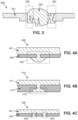
- FIG. 3 shows a sectional view of an assembly 300, according to one embodiment of the invention.
- the assembly 300 comprises an optical element 303 and a frame 301 serving as its support.
- Elements 302 and 304 of the picture 3 represent two types of mechanical hooks made according to a different arrangement. Indeed, in the same way as the picture 2 , the mechanical attachment 302 consists of completely surrounding the frame 301 with the optical element 303, which corresponds to a through hole.
- the mechanical hook 304 is different from the mechanical hook 302. Indeed, for the mechanical hook 304, the frame 301 is shaped so that the optical element 303 penetrates the frame 301 according to the geometry illustrated on the picture 3 . Consequently, the shape of the frame 301 is made beforehand so as to allow such mechanical attachment and thus provide the optical element 303 with the space required within the frame 301 to be inserted therein.
- the mechanical hooks differ within the assembly. Each of these mechanical hooks performs a different function.
- the mechanical hooks 302 and 304 can each prevent a different movement and thus maintain contact and limit the mechanical play between the optical element 303 and the frame 301 so as to form a single piece: the assembly 300.
- the coefficient of thermal expansion is high.
- a frame made of thermoplastic material is also influenced by temperature variations. The temperature variation deforms both the frame and the optical element. It is therefore preferable to take this factor into account in order to avoid thermal deformation of the optical element as well as of the frame serving as its support.
- the temperatures can undergo variations from ⁇ 40° C. to +120° C.
- FIGS. 4A to 4C illustrate mechanical attachments between optical element and frame according to embodiments of the invention. Only the mechanical attachment is represented each time, and it will be understood that only part of the assembly according to the invention is thus represented.
- FIG 4A shows a sectional view of a mechanical attachment according to one embodiment of the invention.
- the assembly 400 comprises a frame 402 and an optical element 401.
- This mechanical attachment 403 is made using a constant section through-hole within frame 402, optical element 401 thus being able to completely pass through frame 402.
- FIG 4B shows a sectional view of a mechanical hook 413 according to one embodiment of the invention.
- the assembly 410 comprises a frame 412 and an optical element 411.
- the mechanical attachment 413 allows contact to be maintained between the optical element 411 and the frame 412.
- the mechanical attachment 413 corresponds to a hole with a non-constant section.
- the hole shown is blind on the figure 4B , but the invention also provides for the use of a through-hole with a non-constant section.
- the section of the hole within the frame 412 increases in the shape of a T.
- the contact surfaces between the optical element and the frame differ from the preceding figures.
- FIG. 4C shows a sectional view of mechanical attachments 423 and 424 according to one embodiment of the invention.
- the assembly 420 comprises a frame 422 and an optical element 421.
- the mechanical hook 423 corresponds to a hole of non-constant section within the frame 422.
- the hole corresponding to the mechanical hook 423 is blind on the Fig. 4C , but the invention also provides for the use of a through-hole with a non-constant section. More specifically, the mechanical hook 423 corresponds to a hole whose section increases with a linear profile.
- the mechanical hook 424 corresponds to a hole of non-constant section within the frame 422.
- the hole corresponding to the mechanical hook 424 is blind on the Fig. 4C , but the invention also provides for the use of a through-hole with a non-constant section.
- the section of the hole corresponding to the mechanical hook 424 does not have an exactly linear profile. The section begins with a parabolic profile then a linear profile.
- the present invention allows a high level of precision concerning the type and number of mechanical attachments for the design of the frame.
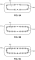
- FIG. 5A shows one embodiment of an assembly according to the invention. More specifically, the figure 5A represents a frame 500 serving as a support for the overmolding of an optical element, not shown in the figure.
- the frame 500 includes a central hole 501 allowing incident light to pass through the optical element when the latter is overmolded on the frame 500.
- the frame 500 can include at least eight holes 502, in particular eight holes, distributed uniformly around the hole central 501 and allowing maintenance of the optical element once overmolded on the frame.
- the holes 502 can be of substantially identical sizes and can be arranged on tabs belonging to the frame 500. The holes 502 are made on the frame 500 prior to the step of overmolding the optical element on the frame 500.
- FIG. 5B represents an embodiment of an assembly according to the invention. More precisely the figure 5B represents a frame 510 serving as a support for the overmolding of an optical element, not shown in the figure.
- the frame 510 includes a central hole 511 allowing incident light to pass through the optical element when the latter is overmolded on the frame 510.
- the frame 510 can include at least sixteen holes, in particular sixteen holes, distributed uniformly around the central hole 511 and allowing the optical element to be held once molded onto the frame.
- the holes 512 can be of substantially identical sizes and arranged on tongues belonging to the frame 510. The increase in the number of holes within the frame makes it possible to increase the mechanical adhesion between the frame and the optical element once it is this overmolded on the frame.
- Fig. 5C represents an embodiment of an assembly according to the invention. More precisely the Fig. 5C represents a frame 520 serving as a support for the overmolding of an optical element, not shown in the figure.
- the frame 520 includes a central hole 521 allowing incident light to pass through the optical element when the latter is overmolded on the frame 520.
- the frame 520 can include at least twenty holes, in particular twenty holes 521 distributed uniformly around the central hole 521 and allowing the optical element to be held once molded onto the frame. Holes 522 may not all be substantially the same size. Indeed, sixteen holes 522 can be of substantially identical sizes, similar to the figure 5B and four additional holes 522 of smaller sizes are inserted on tabs of smaller size as well.
- FIG. 6 represents a diagram illustrating the steps of a method according to one embodiment of the invention. More specifically, the figure 6 comprises two steps 601 and 602 of a method for manufacturing an assembly of an optical element, preferably made of silicone, with a frame serving as its support.
- the first step 601 (FAB_SUP) corresponds to the manufacture of the frame.
- the frame can also be considered as a support.
- the frame can be manufactured by molding in the case of a frame made of thermoplastic material.
- the frame can also be a metal element and therefore be manufactured by machining.
- Step 502 corresponds to a step of overmolding the optical element on the frame. The purpose of this step is to form from two separate parts that are the optical element and the frame a single part: the assembly.
- the frame is shaped so as to produce a mechanical grip between the frame and the optical element during the overmolding of the optical element on the frame.
- the frame is therefore designed with a particular geometry so as to provide the mechanical attachments for the optical element according to the application of said assembly.
Landscapes
- Engineering & Computer Science (AREA)
- General Engineering & Computer Science (AREA)
- Manufacturing & Machinery (AREA)
- Mechanical Engineering (AREA)
- Physics & Mathematics (AREA)
- General Physics & Mathematics (AREA)
- Optics & Photonics (AREA)
- Non-Portable Lighting Devices Or Systems Thereof (AREA)
- Injection Moulding Of Plastics Or The Like (AREA)
- Securing Globes, Refractors, Reflectors Or The Like (AREA)
Description
- La présente invention concerne le domaine de l'assemblage d'un élément sur un cadre pouvant servir de support audit élément, et plus particulièrement l'assemblage d'un élément sur un cadre par surmoulage. L'élément à assembler sur le cadre peut être un élément optique tel qu'une lentille par exemple.
- La présente invention trouve des applications dans le domaine automobile notamment dans le domaine de dispositifs de projection de véhicule automobile dans des applications d'éclairage et/ou de signalisation. Une lentille surmoulée sur un cadre peut ainsi constituer un élément d'un dispositif de projection de véhicule automobile.
- Des méthodes connues de surmoulage d'élément sur un cadre prévoient l'assemblage en une seule pièce d'un élément et d'un cadre lui servant de support. Le but de telles méthodes est d'obtenir une seule pièce à partir de deux pièces distinctes.
US 2007/117248 A1 concerne un boîtier de dispositif électronique ainsi que des procédés de formation du boîtier. - Cependant, ces méthodes ne prévoient pas d'empêcher les déplacements de l'élément surmoulé par rapport au cadre lui servant de support.
- En effet, une fois l'élément surmoulé sur le cadre, il peut exister ou se créer, du fait de différence de température ou d'une usure mécanique, un jeu entre l'élément surmoulé et le cadre associé ou une déformation de l'un de ces éléments.
- Par conséquent, il peut subsister des degrés de liberté dans la liaison entre l'élément surmoulé et cadre lui servant de support.
- De plus, certains matériaux se déformant avec la chaleur tels que les plastiques par exemple, peuvent engendrer des mouvements supplémentaires de l'élément surmoulé par rapport au cadre, voire entraîner une rupture de l'assemblage. En effet, les variations de température peuvent déformer à la fois l'élément surmoulé et le cadre servant de support.
- Il existe donc un besoin de limiter voire d'empêcher le mouvement d'un élément surmoulé par rapport à un cadre lui servant de support et ainsi assurer un maintien de l'assemblage élément surmoulé et cadre associé.
- La présente invention vient améliorer la situation.
- Un premier aspect de l'invention concerne un assemblage (100) optique d'un module lumineux notamment d'éclairage et/ou de signalisation, en particulier pour véhicule automobile, comprenant :
- un élément optique (102);
- un cadre (101);
- ledit élément optique étant surmoulé sur le cadre,
- ledit cadre étant conformé de manière à réaliser une accroche mécanique entre le cadre et l'élément optique suite au surmoulage de l'élément optique sur le cadre.
- On entend par « élément optique » un élément permettant de modifier la trajectoire de rayons lumineux ou les propriétés de la lumière. Par exemple, un élément optique peut correspondre à un miroir ou une lentille en matière thermoplastique telle que le polycarbonate (PC), le polyméthacrylate (PPMA), le copolymère de cyclooléfine (COC), le copolymère de cyololéphine (COP) et le silicone.
- On entend par « cadre » un élément servant de support à l'élément optique.
- On entend par « surmouler » l'action consistant à réaliser un moulage de l'élément optique directement sur le cadre. Il existe plusieurs techniques de surmoulage. Par exemple en plasturgie, le surmoulage consiste à venir injecter du plastique sur un élément servant de support. L'élément de support peut être constitué de divers matériaux : métal, plastique ou céramique par exemple.
- Ainsi l'élément optique et le cadre constituent une seule pièce et l'élément optique épouse la géométrie du cadre. Cela élimine l'utilisation de pièces d'interface et permet d'éviter de multiples étapes d'assemblage. Le nombre de pièces du produit final est réduit et il n'y a pas d'assemblage visible entre l'élément optique et le cadre. Cela permet également d'obtenir une variété de formes plus importante pour l'élément optique.
- Selon un mode de réalisation de l'invention, au moins une surface de contact du cadre avec l'élément optique peut comprendre au moins un trou, dans lequel le trou réalise l'accroche mécanique entre le cadre et l'élément optique suite au surmoulage de l'élément optique sur le cadre.
- Ainsi, l'adhésion physique entre le cadre et l'élément optique surmoulé est renforcée. Les degrés de liberté correspondant aux mouvements relatifs indépendants entre l'élément optique et le cadre sont limités.
- Selon un mode de réalisation de l'invention, ledit au moins un trou comprend un trou traversant de manière à ce que, suite au surmoulage, l'élément optique entoure partiellement le cadre.
- Ainsi, l'utilisation d'un trou traversant permet de limiter les mouvements de l' l'élément optique par rapport au cadre. En effet, dans le cas d'un élément optique en silicone, l'élément optique à tendance à se mouvoir. Ce phénomène est dû au fait que le silicone est un matériau qui reste souple et maintient difficilement sa géométrie. Ces mouvements peuvent aussi être provoqués par des coefficients de dilatation différents lors de l'exposition à la chaleur.
- Selon un mode de réalisation de l'invention, le trou traversant peut posséder une section constante.
- Ainsi, l'opération consistant à effectuer les trous n'introduit pas de difficultés.
- Selon un mode de réalisation de l'invention, ledit au moins trou peut posséder une section croissante non constante.
- Ainsi, l'adhésion mécanique entre l'élément optique et le cadre est renforcée.
- Selon un mode de réalisation de l'invention, ledit au moins trou peut posséder une section non-constante en forme de T.
- Alternativement, la section croissante non constante peut avoir un profil linéaire.
- Selon un mode de réalisation de l'invention, le cadre peut comprendre un trou central agencé de manière à permettre à une lumière de traverser l'élément optique.
- Ainsi, lors du surmoulage de l'élément optique sur le cadre, l'élément optique vient se loger dans le trou central.
- Selon un mode de réalisation de l'invention, le cadre peut comprendre au moins huit trous répartis sensiblement uniformément autour du trou central.
- Ainsi la liaison de l'élément optique sur le cadre est renforcée.
- Selon un mode de réalisation de l'invention, le cadre peut comprendre au moins seize trous répartis sensiblement uniformément autour du trou central.
- Ainsi la liaison de l'élément optique sur le cadre est renforcée.
- Selon un mode de réalisation de l'invention, le cadre peut comprendre au moins vingt trous répartis sensiblement uniformément autour du trou central.
- Ainsi la liaison de l'élément optique sur le cadre est renforcée.
- Selon un mode de réalisation de l'invention, au moins une surface de contact du cadre avec l'élément optique peut comprendre au moins une aspérité, dans lequel l'aspérité réalise l'accroche mécanique entre le cadre et l'élément optique suite au surmoulage de l'élément optique sur le cadre.
- Ainsi, l'adhésion mécanique entre l'élément optique et le cadre est renforcée.
- Selon un mode de réalisation de l'invention, ledit cadre peut être réalisé en une matière thermoplastique et l'élément optique peut être en silicone.
- Ainsi, la liaison mécanique entre l'élément optique et le cadre est renforcée. En effet dans le cas où le cadre est réalisé en matière thermoplastique et l'élément optique est réalisé en silicone ou dans un thermoplastique différent, il existe peu d'adhésion chimique. De plus, le silicone a un coefficient de dilatation thermique élevé et les matières thermoplastiques se déforment également en fonction de la température. Cela peut engendrer un certain jeu mécanique entre les deux éléments : cadre et élément optique. Par conséquent, le fait de surmouler l'élément optique réalisé en silicone sur un cadre en matière thermoplastique, où le cadre est conforme à réaliser une accroche mécanique, permet de limiter les mouvements au sein de l'assemblage.
- Selon un mode de réalisation, ledit cadre peut être en outre relié à un second élément optique, de manière à réaliser une fonction optique par agencement du second élément optique relativement à l'élément optique.
- Un deuxième aspect de l'invention concerne un procédé de fabrication d'un assemblage d'un élément optique, dans une matière telle que le polycarbonate (PC), le polyméthacrylate (PPMA), le copolymère de cyclooléfine (COC), le copolymère de cyololéphine (COP) ou le silicone avec un cadre, dans lequel, le procédé comporte les étapes de :
- fabrication du cadre ;
- surmoulage de l'élément optique sur ledit cadre moulé ;
- Le cadre étant fabriqué de manière à réaliser une accroche mécanique entre le cadre et l'élément optique lors de l'étape de surmoulage de l'élément optique sur le cadre.
- Selon un mode de réalisation, la réalisation du cadre comprend le perçage d'au moins un trou, dans lequel le trou réalise l'accroche mécanique entre le cadre et l'élément optique suite au surmoulage de l'élément optique sur le cadre.
- Selon un mode de réalisation, ledit au moins un trou comprend un trou traversant de manière à ce que, suite au surmoulage, l'élément optique entoure partiellement le cadre.
- Selon un mode de réalisation, ledit trou traversant possède une section constante.
- Selon un mode de réalisation, ledit au moins trou possède une section croissante non constante.
- Selon un mode de réalisation, ledit au moins trou possède une section non-constante en forme de T.
- Selon un mode de réalisation, la section croissante non constante a un profil linéaire.
- Selon un mode de réalisation, la réalisation du cadre comprend en outre le perçage d'un trou central agencé de manière à permettre à une lumière de traverser l'élément optique.
- Selon un mode de réalisation, la réalisation du cadre comprend en outre le perçage d'au moins huit trous répartis sensiblement uniformément autour du trou central.
- Selon un mode de réalisation, la réalisation du cadre comprend le perçage d'au moins seize trous répartis sensiblement uniformément autour du trou central.
- Selon un mode de réalisation, la réalisation du cadre comprend le perçage d'au moins vingt trous répartis sensiblement uniformément autour du trou central.
- Selon un mode de réalisation, la réalisation du cadre est effectuée à l'aide d'une matière thermoplastique et le surmoulage dudit élément optique sur ledit cadre est effectué à l'aide d'une matière silicone.
- Selon un mode de réalisation, le dit procédé peut comprendre en outre une étape de liaison d'un second élément optique audit cadre, de manière à réaliser une fonction optique par agencement du second élément optique relativement à l'élément optique.
- Un troisième aspect de l'invention concerne un module lumineux comprenant un assemblage (100) optique, en particulier pour véhicule automobile, comprenant :
- un élément optique (102);
- un cadre (101);
- ledit élément optique étant surmoulé sur le cadre,
- ledit cadre étant conformé de manière à réaliser une accroche mécanique entre le cadre et l'élément optique suite au surmoulage de l'élément optique sur le cadre.
- Un quatrième aspect de l'invention concerne un dispositif lumineux comprenant un module lumineux et/ou assemblage tel que mentionné ci-dessus.
- Un cinquième aspect de l'invention concerne un véhicule comprenant un module lumineux et/ou dispositif lumineux et/ou assemblage tel que mentionné précédemment.
- Un dispositif lumineux peut être un projecteur avant ou un feu arrière ou peut encore être un dispositif d'éclairage adapté pour l'éclairage intérieur du véhicule automobile.
- D'autres caractéristiques et avantages de l'invention apparaîtront à l'examen de la description détaillée ci-après, et des dessins annexés sur lesquels:
- la
figure 1 illustre un assemblage, selon un mode de réalisation de l'invention ; - la
figure 2 représente une vue en coupe d'un assemblage, selon un mode de réalisation de l'invention ; - la
figure 3 représente une vue en coupe d'un assemblage, selon un mode de réalisation de l'invention ; - les
figure 4A, 4B et 4C représente plusieurs vues en coupe, selon différents modes de réalisation de l'invention ; - les
figure 5A, 5B et 5C représente plusieurs modes de réalisation différents de l'invention ; - la
figure 6 est un diagramme illustrant les étapes d'un procédé selon un mode de réalisation de l'invention. - La
figure 1 représente un assemblage 100 comprenant un élément optique 102 et un cadre 101 servant de support à l'élément optique 102. L'élément optique 102 est de préférence en silicone et peut par exemple être une lentille. Aucune limitation n'est attachée à la fonction optique remplie par l'élément optique 102. L'élément optique 102 est surmoulé sur le cadre 101 de manière à former une seule pièce : l'assemblage 100. - De manière avantageuse, le cadre 101 peut être pourvu d'un trou central autour duquel l'élément optique 102 est surmoulé afin de permettre à une lumière incidente de traverser l'élément optique 102. Le cadre peut présenter des supports de fixation 103 permettant d'intégrer l'assemblage 100 dans un module lumineux, par exemple d'éclairage et/ou de signalisation pour véhicule automobile. La forme et la disposition des supports de fixation 103 sur la
figure 1 constituent uniquement un exemple de fixation de l'assemblage 100. - La forme du cadre 101 selon l'invention permet l'assemblage avec l'élément optique 102. En effet, nous verrons dans la suite que la conception du cadre 101 influence la fixation de l'élément optique 102 suite au surmoulage de l'élément optique 102 sur le cadre 101.
- Le cadre 101 servant de support à l'élément optique 102 peut être moulé, par exemple dans le cas où le cadre 101 est réalisé en matière thermoplastique. Toutefois, aucune limitation n'est attachée à la manière de réaliser le cadre.
- La conception d'un moule pour le cadre 101 présentant la géométrie et les caractéristiques décrites ci-après et permettant la fixation de l'élément optique 102 suite à l'étape de surmoulage, peut être réalisée au préalable. Le cadre 101 peut également être une pièce en métal, réalisé par exemple par usinage.
- La
figure 1 représente plus particulièrement une vue dans un plan perpendiculaire à des rayons lumineux atteignant l'élément optique 102, de l'assemblage 100 comprenant le cadre 101 et l'élément optique 102. - La
figure 2 représente une vue en coupe de l'assemblage 100 comprenant un cadre 101 et un élément optique 102, selon un mode de réalisation de l'invention. Plus particulièrement, lafigure 2 représente une vue en coupe issue d'une représentation en trois dimensions de l'assemblage 100 selon un plan perpendiculaire au plan de lafigure 1 . On distingue sur lafigure 2 que l'élément optique 102 entoure complètement le cadre aux emplacements 103. Les emplacements 103 correspondent à des trous traversants dans le cadre 101. En effet, lors du surmoulage de l'élément optique 102 sur le cadre 101, l'élément optique 102 surmoulé vient complètement entourer le cadre 101 aux emplacements 103. Ceci a pour but de renforcer l'adhésion mécanique entre le cadre 101 et l'élément optique 102, et d'empêcher que l'élément optique 102 ne se désolidarise du cadre 101. La manière dont l'élément optique 102 vient entourer le cadre 101 aux deux emplacements 103 est identique. Cependant, rien n'impose que la conception du cadre ne présente deux trous traversants et identiques. On peut considérer les éléments 103 de lafigure 2 en tant qu'accroche mécanique au sens de l'invention. - On distingue sur la
figure 2 qu'il n'y a pas de fixation visible entre l'élément optique 102 et le cadre 101, l'assemblage 100 constitue bien une seule et unique pièce. - La
figure 3 représente une vue en coupe d'un assemblage 300, selon un mode de réalisation de l'invention. L'assemblage 300 comprend un élément optique 303 et un cadre 301 lui servant de support. Les éléments 302 et 304 de lafigure 3 représentent deux types d'accroches mécaniques réalisées selon un arrangement différent. En effet, de la même manière qu'à lafigure 2 , l'accroche mécanique 302 consiste à entourer complètement le cadre 301 avec l'élément optique 303, ce qui correspond à un trou traversant. - L'accroche mécanique 304 est différente de l'accroche mécanique 302. En effet, pour l'accroche mécanique 304, le cadre 301 est conformé de manière à ce que l'élément optique 303 pénètre le cadre 301 selon la géométrie illustrée sur la
figure 3 . Par conséquent, la forme du cadre 301 est préalablement réalisée de manière à permettre une telle d'accroche mécanique et ainsi fournir à l'élément optique 303 l'espace requis au sein du cadre 301 pour s'y insérer. Dans l'exemple de lafigure 3 , les accroches mécaniques diffèrent au sein de l'assemblage. Chacune de ces accroches mécaniques remplit une fonction différente. Les accroches mécaniques 302 et 304 peuvent chacune empêcher un mouvement différent et ainsi maintenir le contact et limiter le jeu mécanique entre l'élément optique 303 et le cadre 301 de manière à former une seule pièce : l'assemblage 300. - Plusieurs paramètres sont pris en compte pour la géométrie et la disposition des accroches mécaniques, tels que la température par exemple. En effet, pour un élément optique réalisé en silicone, le coefficient de dilatation thermique est élevé. Un cadre réalisé en matière thermoplastique est également influencé par les variations de température. La variation de température déforme à la fois le cadre et l'élément optique. Il est par conséquent préférable de prendre en compte ce facteur pour éviter la déformation thermique de l'élément optique ainsi que du cadre lui servant de support. Par exemple dans le cas d'intégration d'un tel assemblage au sein d'un dispositif de projection pour véhicule automobile, les températures peuvent subir des variations de -40°C à +120°C.
- De plus, dans le cas d'un cadre en matière thermoplastique et d'un élément optique en silicone ou matière thermoplastique différente, il existe une faible adhésion chimique entre les deux éléments. Il est donc avantageux d'imposer une certaine géométrie sur le cadre servant de support à l'élément optique afin de réaliser des accroches mécaniques empêchant tout mouvement non prévu, comme le prévoit la présente invention.
- Les
figures 4A à 4C illustrent des accroches mécaniques entre élément optique et cadre selon des modes de réalisation de l'invention. Seule l'accroche mécanique est à chaque fois représentée, et on comprendra que seule une partie de l'assemblage selon l'invention est ainsi représentée. - La
figure 4A représente une vue en coupe d'une accroche mécanique selon un mode de réalisation de l'invention. L'assemblage 400 comprend un cadre 402 et un élément optique 401. On distingue également une accroche mécanique 403 permettant le maintien du contact entre l'élément optique 401 et le cadre 402. Cette accroche mécanique 403 est réalisée à l'aide d'un trou traversant à section constante au sein du cadre 402, l'élément optique 401 pouvant ainsi traverser complètement le cadre 402. - On remarque sur la
figure 4A que l'accroche mécanique 403 diffère des accroches mécaniques représentées sur les figures précédentes. Varier la géométrie et les caractéristiques du cadre 402 permet de multiples possibilités concernant la conception de l'élément optique ainsi que la conception des accroches mécaniques. En effet, lors du surmoulage l'élément optique 401 vient épouser la géométrie du cadre 402. - La
figure 4B représente une vue en coupe d'une accroche mécanique 413 selon un mode de réalisation de l'invention. L'assemblage 410 comprend un cadre 412 et un élément optique 411. L'accroche mécanique 413 permet le maintien du contact entre l'élément optique 411 et le cadre 412. L'accroche mécanique 413 correspond à un trou à section non constante. Le trou représenté est borgne sur lafigure 4B , mais l'invention prévoit également l'utilisation d'un trou traversant à section non constante. La section du trou au sein du cadre 412 est croissante en forme de T. Les surfaces de contact entre l'élément optique et le cadre diffèrent des figures précédentes. - Il est possible de concevoir sur un logiciel de conception assisté par ordinateur les surfaces de contact entre un élément optique et un cadre lui servant de support pour caractériser cet ensemble en tant qu'assemblage. En effet, une fois les surfaces de contact ainsi que les contours de l'élément optique et du cadre dessinés dans le plan, il est possible par extrusion d'obtenir un modèle représentant l'assemblage en trois dimensions. Ce modèle de l'assemblage tridimensionnel peut ensuite être utilisé pour la fabrication.
- La
figure4C représente une vue en coupe d'accroches mécaniques 423 et 424 selon un mode de réalisation de l'invention. L'assemblage 420 comprend un cadre 422 et un élément optique 421. L'accroche mécanique 423 correspond à un trou à section non constante au sein du cadre 422. Le trou correspondant à l'accroche mécanique 423 est borgne sur lafigure 4C , mais l'invention prévoit également l'utilisation d'un trou traversant à section non constante. Plus précisément, l'accroche mécanique 423 correspond à un trou dont la section est croissante avec un profil linéaire. - L'accroche mécanique 424 correspond à un trou à section non constante au sein du cadre 422. Le trou correspondant à l'accroche mécanique 424 est borgne sur la
figure 4C , mais l'invention prévoit également l'utilisation d'un trou traversant à section non constante. La section du trou correspondant à l'accroche mécanique 424 n'a pas un profil exactement linéaire. La section débute par un profil parabolique puis un profil linéaire. - Ainsi, en fonction de l'application, du type de matériau employé et des contraintes imposés, la présente invention permet un haut niveau de précision concernant le type et le nombre d'accroches mécaniques pour la conception du cadre.
- La figre 5A représente un mode de réalisation d'un assemblage selon l'invention. Plus précisément, la
figure 5A représente un cadre 500 servant de support pour le surmoulage d'un élément optique, non représenté sur la figure. Le cadre 500 comporte un trou central 501 permettant à une lumière incidente de traverser l'élément optique lorsque ce dernier est surmoulé sur le cadre 500. Le cadre 500 peut comprendre au moins huit trous 502, en particulier huit trous, répartis uniformément autour du trou central 501 et permettant un maintien de l'élément optique une fois surmoulé sur le cadre. Les trous 502 peuvent être de tailles sensiblement identiques et peuvent être disposés sur des languettes appartenant au cadre 500. Les trous 502 sont réalisés sur le cadre 500 préalablement à l'étape de surmoulage de l'élément optique sur le cadre 500. - La
figure 5B représente un mode de réalisation d'un assemblage selon l'invention. Plus précisément lafigure 5B représente un cadre 510 servant de support pour le surmoulage d'un élément optique, non représenté sur la figure. Le cadre 510 comporte un trou central 511 permettant à une lumière incidente de traverser l'élément optique lorsque ce dernier est surmoulé sur le cadre 510. Le cadre 510 peut comprendre au moins seize trous, en particulier seize trous, répartis uniformément autour du trou central 511 et permettant un maintien de l'élément optique une fois surmoulé sur le cadre. Les trous 512 peuvent être de tailles sensiblement identiques et disposés sur des languettes appartenant au cadre 510. L'augmentation du nombre de trous au sein du cadre permet d'augment l'adhésion mécanique entre le cadre et l'élément optique une fois celui-ci surmoulé sur le cadre. - La
figure 5C représente un mode de réalisation d'un assemblage selon l'invention. Plus précisément lafigure 5C représente un cadre 520 servant de support pour le surmoulage d'un élément optique, non représenté sur la figure. Le cadre 520 comporte un trou central 521 permettant à une lumière incidente de traverser l'élément optique lorsque ce dernier est surmoulé sur le cadre 520. Le cadre 520 peut comprendre au moins vingt trous, en particulier vingt trous 521 répartis uniformément autour du trou central 521 et permettant un maintien de l'élément optique une fois surmoulé sur le cadre. Les trous 522 peuvent ne pas être tous de tailles sensiblement identiques. En effet, seize trous 522 peuvent être de tailles sensiblement identiques, similairement à lafigure 5B et quatre trous supplémentaires 522 de tailles inférieures sont insérés sur des languettes de taille inférieure également. - La
figure 6 représente un diagramme illustrant les étapes d'un procédé selon un mode de réalisation de l'invention. Plus précisément, lafigure 6 comprend deux étapes 601 et 602 d'un procédé de fabrication d'un assemblage d'un élément optique, de préférence en silicone avec un cadre lui servant de support. La première étape 601 (FAB_SUP) correspond à la fabrication du cadre. Le cadre peut également être considéré comme un support. Le cadre peut être fabriqué par moulage dans le cas d'un cadre en matière thermoplastique. Le cadre peut également être un élément en métal et donc être fabriquer par usinage. L'étape 502 (MOL_ELT) correspond à une étape de surmoulage de l'élément optique sur le cadre. Le but de cette étape est de former à partir de deux pièces distinctes que sont l'élément optique et le cadre une seule pièce : l'assemblage. Quel que soit le procédé de fabrication du cadre lors de l'étape 601, le cadre est conformé de manière à réaliser une accroche mécanique entre le cadre et l'élément optique lors du surmoulage de l'élément optique sur le cadre. Le cadre est donc conçu avec une géométrie particulière de manière à fournir les accroches mécaniques pour l'élément optique en fonction de l'application dudit assemblage. - Bien entendu, l'invention n'est pas limitée aux modes de réalisation décrits précédemment et fournis uniquement à titre d'exemple. Elle englobe diverses modifications, formes alternatives et autres variantes que pourra envisager l'homme du métier dans le cadre de la présente invention et notamment toutes combinaisons des différents modes de réalisation décrits précédemment.
Claims (10)
- Assemblage (100) optique d'un module lumineux d'éclairage et/ou de signalisation, de véhicule automobile, comprenant :- un élément optique (102, 303, 401, 411, 421);- un cadre (101, 301, 402, 412, 422);ledit élément optique étant surmoulé sur le cadre,ledit cadre étant conformé de manière à réaliser une accroche mécanique entre le cadre et l'élément optique suite au surmoulage de l'élément optique sur le cadre,au moins une surface de contact du cadre (101, 301, 402, 412, 422) avec l'élément optique (102, 303, 401, 411, 421) comprenant au moins un trou, le trou réalisant l'accroche mécanique entre le cadre et l'élément optique suite au surmoulage de l'élément optique sur le cadre,caractérisé en ce que ledit au moins un trou comprend un trou traversant de manière à ce que, suite au surmoulage, l'élément optique (102, 303, 401, 411, 421) entoure partiellement le cadre (101, 301, 402, 412, 422),et en ce que le cadre comprend un trou central agencé de manière à permettre à une lumière de traverser l'élément optique.
- Assemblage selon la revendication 1, dans lequel le cadre (101, 301, 402, 412, 422) comprend au moins huit trous répartis sensiblement uniformément autour du trou central.
- Assemblage selon la revendication 2, dans lequel le cadre (101, 301, 402, 412, 422) comprend au moins seize trous répartis sensiblement uniformément autour du trou central.
- Assemblage selon la revendication 3, dans lequel le cadre (101, 301, 402, 412, 422) comprend au moins vingt trous répartis sensiblement uniformément autour du trou central.
- Assemblage selon l'une des revendications précédentes, dans lequel au moins une surface de contact du cadre avec l'élément optique (102, 303, 401, 411, 421) comprend au moins une aspérité, dans lequel l'aspérité réalise l'accroche mécanique entre le cadre (101, 301, 402, 412, 422) et l'élément optique suite au surmoulage de l'élément optique sur le cadre.
- Assemblage selon l'une des revendications précédentes, dans lequel ledit cadre (101, 301, 402, 412, 422) est réalisé en une matière thermoplastique et l'élément optique est en silicone.
- Assemblage selon l'une des revendications précédentes, dans lequel ledit cadre (101, 301, 402, 412, 422) est en outre relié à un second élément optique, de manière à réaliser une fonction optique par agencement du second élément optique relativement à l'élément optique.
- Procédé de fabrication d'un assemblage optique d'un module lumineux, notamment d'éclairage et/ou de signalisation, en particulier pour véhicule automobile, dans lequel, le procédé comporte les étapes de :- réalisation d'un cadre (601) ;- surmoulage d'un élément optique sur ledit cadre (602) ;ledit cadre étant réalisé de manière à réaliser une accroche mécanique entre le cadre et l'élément optique lors de l'étape de surmoulage de l'élément optique sur le cadrela réalisation du cadre comprenant le perçage d'au moins un trou, dans lequel le trou réalise l'accroche mécanique entre le cadre et l'élément optique suite au surmoulage de l'élément optique sur le cadre, etledit au moins un trou comprenant un trou traversant de manière à ce que, suite au surmoulage, l'élément optique entoure partiellement le cadre,la réalisation du cadre comprenant en outre le perçage d'un trou central agencé de manière à permettre à une lumière de traverser l'élément optique.
- Procédé selon la revendication 8, dans lequel la réalisation du cadre (601) est effectuée à l'aide d'une matière thermoplastique et le surmoulage dudit élément optique sur ledit cadre (602) est effectuée à l'aide silicone.
- Procédé selon l'une des revendications 8 à 9 comprenant en outre une étape de liaison d'un second élément optique audit cadre, de manière à réaliser une fonction optique par agencement du second élément optique relativement à l'élément optique.
Applications Claiming Priority (1)
| Application Number | Priority Date | Filing Date | Title |
|---|---|---|---|
| FR1753222A FR3065276B1 (fr) | 2017-04-12 | 2017-04-12 | Surmoulage d’un element optique sur un cadre thermoplastique |
Publications (2)
| Publication Number | Publication Date |
|---|---|
| EP3388218A1 EP3388218A1 (fr) | 2018-10-17 |
| EP3388218B1 true EP3388218B1 (fr) | 2023-04-26 |
Family
ID=59031193
Family Applications (1)
| Application Number | Title | Priority Date | Filing Date |
|---|---|---|---|
| EP18166395.6A Active EP3388218B1 (fr) | 2017-04-12 | 2018-04-09 | Surmoulage d'un élément optique sur un cadre thermoplastique |
Country Status (5)
| Country | Link |
|---|---|
| US (1) | US10946564B2 (fr) |
| EP (1) | EP3388218B1 (fr) |
| JP (1) | JP7046685B2 (fr) |
| CN (1) | CN108693615A (fr) |
| FR (1) | FR3065276B1 (fr) |
Families Citing this family (2)
| Publication number | Priority date | Publication date | Assignee | Title |
|---|---|---|---|---|
| CN214536006U (zh) * | 2021-02-05 | 2021-10-29 | 华域视觉科技(上海)有限公司 | 车灯光学元件、车灯照明装置、车灯及车辆 |
| EP4234412B1 (fr) | 2022-02-23 | 2025-04-30 | Goodrich Lighting Systems GmbH & Co. KG | Lumière d'aéronef, aéronef, et procédé d'assemblage d'une lumière d'aéronef |
Citations (1)
| Publication number | Priority date | Publication date | Assignee | Title |
|---|---|---|---|---|
| US20170023762A1 (en) * | 2015-07-22 | 2017-01-26 | Canon Kabushiki Kaisha | Optical part, method of manufacturing the optical part, and camera |
Family Cites Families (6)
| Publication number | Priority date | Publication date | Assignee | Title |
|---|---|---|---|---|
| JPS60141518A (ja) * | 1983-12-29 | 1985-07-26 | Matsushita Electric Ind Co Ltd | レンズ成形方法 |
| JPS60156502U (ja) * | 1984-03-29 | 1985-10-18 | 株式会社 オ−デイオテクニカ | ハイブリツト・レンズ |
| JPS611067A (ja) * | 1984-06-13 | 1986-01-07 | Stanley Electric Co Ltd | プリント基板に装着されたledチツプのモ−ルド方法 |
| FR2836714B1 (fr) * | 2002-03-01 | 2004-10-22 | Holophane | Projecteur comprenant une lentille en verre et un support de lentille en matiere plastique et outil de surmoulage du support sur la lentille |
| WO2005056269A2 (fr) * | 2003-12-09 | 2005-06-23 | G.L.I. Global Light Industries Gmbh | Procede pour produire des diodes electroluminescentes a semi-conducteurs sur une platine, et unites lumineuses a platine integree |
| US8646637B2 (en) | 2008-04-18 | 2014-02-11 | Apple Inc. | Perforated substrates for forming housings |
-
2017
- 2017-04-12 FR FR1753222A patent/FR3065276B1/fr not_active Expired - Fee Related
-
2018
- 2018-04-09 EP EP18166395.6A patent/EP3388218B1/fr active Active
- 2018-04-11 JP JP2018076220A patent/JP7046685B2/ja active Active
- 2018-04-12 US US15/951,616 patent/US10946564B2/en active Active
- 2018-04-12 CN CN201810328519.0A patent/CN108693615A/zh active Pending
Patent Citations (1)
| Publication number | Priority date | Publication date | Assignee | Title |
|---|---|---|---|---|
| US20170023762A1 (en) * | 2015-07-22 | 2017-01-26 | Canon Kabushiki Kaisha | Optical part, method of manufacturing the optical part, and camera |
Also Published As
| Publication number | Publication date |
|---|---|
| FR3065276B1 (fr) | 2019-11-29 |
| US10946564B2 (en) | 2021-03-16 |
| EP3388218A1 (fr) | 2018-10-17 |
| FR3065276A1 (fr) | 2018-10-19 |
| JP7046685B2 (ja) | 2022-04-04 |
| US20180297249A1 (en) | 2018-10-18 |
| CN108693615A (zh) | 2018-10-23 |
| JP2018183986A (ja) | 2018-11-22 |
Similar Documents
| Publication | Publication Date | Title |
|---|---|---|
| EP3134246B1 (fr) | Procédé de fabrication d'une roue dentée allégée par surmoulage double | |
| EP3388218B1 (fr) | Surmoulage d'un élément optique sur un cadre thermoplastique | |
| WO2010023391A1 (fr) | Panneau de garnissage de vehicule automobile comprenant un pictogramme et un materiau de transmisison de la lumiere | |
| WO2010076504A1 (fr) | Garniture de moule pour pneumatique comprenant un element sacrificiel de liaison | |
| EP3408925A1 (fr) | Ensemble de support d'un moteur électrique, notamment dans un dispositif de chauffage, ventilation et/ou climatisation pour véhicule automobile | |
| CA3003818A1 (fr) | Procede et moule pour la realisation d'un element aerodynamique comportant des riblets | |
| EP1796891B1 (fr) | Procede et dispositif de fabrication d'un boyau profile. | |
| EP4414216A1 (fr) | Panneau d'habillage pour véhicule automobile comprenant une zone de transmission de lumière et une zone de masquage | |
| EP4072904B1 (fr) | Panneau de carrosserie de véhicule automobile comprenant une partie transparente | |
| FR2946562A1 (fr) | Procede de postionnement et d'assemblage de deux pieces dont l'une au moins est moulee en un materiau sensible au fluage | |
| EP1346809B1 (fr) | Procédé de fabrication d'une articulation montée sur un support | |
| FR2967507A1 (fr) | Procede de fabrication d'un dispositif de miroir a plusieurs composants et dispositif obtenu | |
| EP3703836B1 (fr) | Procédé de fabrication d'un objet musical et objet musical obtenu | |
| FR2952876A1 (fr) | Calandre, notamment pour vehicule automobile, a fonction esthetique amelioree | |
| FR2957581A1 (fr) | Ensemble de grille d'entree d'air de vehicule automobile | |
| FR3059587A1 (fr) | Composant pour une partie de garniture interieure de vehicule et procede de fabrication d'un composant | |
| FR3041415A1 (fr) | Guide de lumiere pour signaletique longiligne continue. | |
| FR3139495A1 (fr) | Procédé de moulage de panneau de carrosserie | |
| EP3559481B1 (fr) | Pièce de véhicule automobile comportant un fût de vissage orientable | |
| WO2015091344A1 (fr) | Vanne de commande avec segment d'etancheite moule comportant une bavure localisee dans un retrait | |
| FR3087700A1 (fr) | Procede de fabrication d'une peau | |
| FR2975342A1 (fr) | Valve de roue notamment pour vehicule a grande vitesse | |
| EP4372485A1 (fr) | Fabrication d'un composant horloger et composant horloger | |
| FR3161259A1 (fr) | Enveloppe d’un dispositif lumineux de véhicule comprenant au moins un coussinet d’interface mécanique. | |
| EP1234656A1 (fr) | Roue, notamment pour vehicules legers, et son procede de fabrication |
Legal Events
| Date | Code | Title | Description |
|---|---|---|---|
| PUAI | Public reference made under article 153(3) epc to a published international application that has entered the european phase |
Free format text: ORIGINAL CODE: 0009012 |
|
| STAA | Information on the status of an ep patent application or granted ep patent |
Free format text: STATUS: REQUEST FOR EXAMINATION WAS MADE |
|
| 17P | Request for examination filed |
Effective date: 20180409 |
|
| AK | Designated contracting states |
Kind code of ref document: A1 Designated state(s): AL AT BE BG CH CY CZ DE DK EE ES FI FR GB GR HR HU IE IS IT LI LT LU LV MC MK MT NL NO PL PT RO RS SE SI SK SM TR |
|
| AX | Request for extension of the european patent |
Extension state: BA ME |
|
| STAA | Information on the status of an ep patent application or granted ep patent |
Free format text: STATUS: EXAMINATION IS IN PROGRESS |
|
| 17Q | First examination report despatched |
Effective date: 20191126 |
|
| GRAP | Despatch of communication of intention to grant a patent |
Free format text: ORIGINAL CODE: EPIDOSNIGR1 |
|
| STAA | Information on the status of an ep patent application or granted ep patent |
Free format text: STATUS: GRANT OF PATENT IS INTENDED |
|
| RIC1 | Information provided on ipc code assigned before grant |
Ipc: B29K 83/00 20060101ALN20221117BHEP Ipc: F21S 41/29 20180101ALI20221117BHEP Ipc: F21S 41/26 20180101ALI20221117BHEP Ipc: B29C 45/14 20060101AFI20221117BHEP |
|
| INTG | Intention to grant announced |
Effective date: 20221201 |
|
| GRAS | Grant fee paid |
Free format text: ORIGINAL CODE: EPIDOSNIGR3 |
|
| GRAA | (expected) grant |
Free format text: ORIGINAL CODE: 0009210 |
|
| STAA | Information on the status of an ep patent application or granted ep patent |
Free format text: STATUS: THE PATENT HAS BEEN GRANTED |
|
| AK | Designated contracting states |
Kind code of ref document: B1 Designated state(s): AL AT BE BG CH CY CZ DE DK EE ES FI FR GB GR HR HU IE IS IT LI LT LU LV MC MK MT NL NO PL PT RO RS SE SI SK SM TR |
|
| REG | Reference to a national code |
Ref country code: GB Ref legal event code: FG4D Free format text: NOT ENGLISH |
|
| REG | Reference to a national code |
Ref country code: CH Ref legal event code: EP |
|
| REG | Reference to a national code |
Ref country code: DE Ref legal event code: R096 Ref document number: 602018048814 Country of ref document: DE |
|
| REG | Reference to a national code |
Ref country code: AT Ref legal event code: REF Ref document number: 1562519 Country of ref document: AT Kind code of ref document: T Effective date: 20230515 |
|
| REG | Reference to a national code |
Ref country code: IE Ref legal event code: FG4D Free format text: LANGUAGE OF EP DOCUMENT: FRENCH |
|
| P01 | Opt-out of the competence of the unified patent court (upc) registered |
Effective date: 20230528 |
|
| REG | Reference to a national code |
Ref country code: LT Ref legal event code: MG9D |
|
| REG | Reference to a national code |
Ref country code: NL Ref legal event code: MP Effective date: 20230426 |
|
| REG | Reference to a national code |
Ref country code: AT Ref legal event code: MK05 Ref document number: 1562519 Country of ref document: AT Kind code of ref document: T Effective date: 20230426 |
|
| PG25 | Lapsed in a contracting state [announced via postgrant information from national office to epo] |
Ref country code: NL Free format text: LAPSE BECAUSE OF FAILURE TO SUBMIT A TRANSLATION OF THE DESCRIPTION OR TO PAY THE FEE WITHIN THE PRESCRIBED TIME-LIMIT Effective date: 20230426 |
|
| PG25 | Lapsed in a contracting state [announced via postgrant information from national office to epo] |
Ref country code: SE Free format text: LAPSE BECAUSE OF FAILURE TO SUBMIT A TRANSLATION OF THE DESCRIPTION OR TO PAY THE FEE WITHIN THE PRESCRIBED TIME-LIMIT Effective date: 20230426 Ref country code: PT Free format text: LAPSE BECAUSE OF FAILURE TO SUBMIT A TRANSLATION OF THE DESCRIPTION OR TO PAY THE FEE WITHIN THE PRESCRIBED TIME-LIMIT Effective date: 20230828 Ref country code: NO Free format text: LAPSE BECAUSE OF FAILURE TO SUBMIT A TRANSLATION OF THE DESCRIPTION OR TO PAY THE FEE WITHIN THE PRESCRIBED TIME-LIMIT Effective date: 20230726 Ref country code: ES Free format text: LAPSE BECAUSE OF FAILURE TO SUBMIT A TRANSLATION OF THE DESCRIPTION OR TO PAY THE FEE WITHIN THE PRESCRIBED TIME-LIMIT Effective date: 20230426 Ref country code: AT Free format text: LAPSE BECAUSE OF FAILURE TO SUBMIT A TRANSLATION OF THE DESCRIPTION OR TO PAY THE FEE WITHIN THE PRESCRIBED TIME-LIMIT Effective date: 20230426 |
|
| PG25 | Lapsed in a contracting state [announced via postgrant information from national office to epo] |
Ref country code: RS Free format text: LAPSE BECAUSE OF FAILURE TO SUBMIT A TRANSLATION OF THE DESCRIPTION OR TO PAY THE FEE WITHIN THE PRESCRIBED TIME-LIMIT Effective date: 20230426 Ref country code: PL Free format text: LAPSE BECAUSE OF FAILURE TO SUBMIT A TRANSLATION OF THE DESCRIPTION OR TO PAY THE FEE WITHIN THE PRESCRIBED TIME-LIMIT Effective date: 20230426 Ref country code: LV Free format text: LAPSE BECAUSE OF FAILURE TO SUBMIT A TRANSLATION OF THE DESCRIPTION OR TO PAY THE FEE WITHIN THE PRESCRIBED TIME-LIMIT Effective date: 20230426 Ref country code: LT Free format text: LAPSE BECAUSE OF FAILURE TO SUBMIT A TRANSLATION OF THE DESCRIPTION OR TO PAY THE FEE WITHIN THE PRESCRIBED TIME-LIMIT Effective date: 20230426 Ref country code: IS Free format text: LAPSE BECAUSE OF FAILURE TO SUBMIT A TRANSLATION OF THE DESCRIPTION OR TO PAY THE FEE WITHIN THE PRESCRIBED TIME-LIMIT Effective date: 20230826 Ref country code: HR Free format text: LAPSE BECAUSE OF FAILURE TO SUBMIT A TRANSLATION OF THE DESCRIPTION OR TO PAY THE FEE WITHIN THE PRESCRIBED TIME-LIMIT Effective date: 20230426 Ref country code: GR Free format text: LAPSE BECAUSE OF FAILURE TO SUBMIT A TRANSLATION OF THE DESCRIPTION OR TO PAY THE FEE WITHIN THE PRESCRIBED TIME-LIMIT Effective date: 20230727 |
|
| PG25 | Lapsed in a contracting state [announced via postgrant information from national office to epo] |
Ref country code: FI Free format text: LAPSE BECAUSE OF FAILURE TO SUBMIT A TRANSLATION OF THE DESCRIPTION OR TO PAY THE FEE WITHIN THE PRESCRIBED TIME-LIMIT Effective date: 20230426 |
|
| PG25 | Lapsed in a contracting state [announced via postgrant information from national office to epo] |
Ref country code: SK Free format text: LAPSE BECAUSE OF FAILURE TO SUBMIT A TRANSLATION OF THE DESCRIPTION OR TO PAY THE FEE WITHIN THE PRESCRIBED TIME-LIMIT Effective date: 20230426 |
|
| REG | Reference to a national code |
Ref country code: DE Ref legal event code: R097 Ref document number: 602018048814 Country of ref document: DE |
|
| PG25 | Lapsed in a contracting state [announced via postgrant information from national office to epo] |
Ref country code: SM Free format text: LAPSE BECAUSE OF FAILURE TO SUBMIT A TRANSLATION OF THE DESCRIPTION OR TO PAY THE FEE WITHIN THE PRESCRIBED TIME-LIMIT Effective date: 20230426 Ref country code: SK Free format text: LAPSE BECAUSE OF FAILURE TO SUBMIT A TRANSLATION OF THE DESCRIPTION OR TO PAY THE FEE WITHIN THE PRESCRIBED TIME-LIMIT Effective date: 20230426 Ref country code: RO Free format text: LAPSE BECAUSE OF FAILURE TO SUBMIT A TRANSLATION OF THE DESCRIPTION OR TO PAY THE FEE WITHIN THE PRESCRIBED TIME-LIMIT Effective date: 20230426 Ref country code: EE Free format text: LAPSE BECAUSE OF FAILURE TO SUBMIT A TRANSLATION OF THE DESCRIPTION OR TO PAY THE FEE WITHIN THE PRESCRIBED TIME-LIMIT Effective date: 20230426 Ref country code: DK Free format text: LAPSE BECAUSE OF FAILURE TO SUBMIT A TRANSLATION OF THE DESCRIPTION OR TO PAY THE FEE WITHIN THE PRESCRIBED TIME-LIMIT Effective date: 20230426 Ref country code: CZ Free format text: LAPSE BECAUSE OF FAILURE TO SUBMIT A TRANSLATION OF THE DESCRIPTION OR TO PAY THE FEE WITHIN THE PRESCRIBED TIME-LIMIT Effective date: 20230426 |
|
| PLBE | No opposition filed within time limit |
Free format text: ORIGINAL CODE: 0009261 |
|
| STAA | Information on the status of an ep patent application or granted ep patent |
Free format text: STATUS: NO OPPOSITION FILED WITHIN TIME LIMIT |
|
| 26N | No opposition filed |
Effective date: 20240129 |
|
| PG25 | Lapsed in a contracting state [announced via postgrant information from national office to epo] |
Ref country code: SI Free format text: LAPSE BECAUSE OF FAILURE TO SUBMIT A TRANSLATION OF THE DESCRIPTION OR TO PAY THE FEE WITHIN THE PRESCRIBED TIME-LIMIT Effective date: 20230426 |
|
| PG25 | Lapsed in a contracting state [announced via postgrant information from national office to epo] |
Ref country code: SI Free format text: LAPSE BECAUSE OF FAILURE TO SUBMIT A TRANSLATION OF THE DESCRIPTION OR TO PAY THE FEE WITHIN THE PRESCRIBED TIME-LIMIT Effective date: 20230426 Ref country code: IT Free format text: LAPSE BECAUSE OF FAILURE TO SUBMIT A TRANSLATION OF THE DESCRIPTION OR TO PAY THE FEE WITHIN THE PRESCRIBED TIME-LIMIT Effective date: 20230426 |
|
| PG25 | Lapsed in a contracting state [announced via postgrant information from national office to epo] |
Ref country code: BG Free format text: LAPSE BECAUSE OF FAILURE TO SUBMIT A TRANSLATION OF THE DESCRIPTION OR TO PAY THE FEE WITHIN THE PRESCRIBED TIME-LIMIT Effective date: 20230426 |
|
| PG25 | Lapsed in a contracting state [announced via postgrant information from national office to epo] |
Ref country code: MC Free format text: LAPSE BECAUSE OF FAILURE TO SUBMIT A TRANSLATION OF THE DESCRIPTION OR TO PAY THE FEE WITHIN THE PRESCRIBED TIME-LIMIT Effective date: 20230426 |
|
| PG25 | Lapsed in a contracting state [announced via postgrant information from national office to epo] |
Ref country code: MC Free format text: LAPSE BECAUSE OF FAILURE TO SUBMIT A TRANSLATION OF THE DESCRIPTION OR TO PAY THE FEE WITHIN THE PRESCRIBED TIME-LIMIT Effective date: 20230426 Ref country code: BG Free format text: LAPSE BECAUSE OF FAILURE TO SUBMIT A TRANSLATION OF THE DESCRIPTION OR TO PAY THE FEE WITHIN THE PRESCRIBED TIME-LIMIT Effective date: 20230426 |
|
| REG | Reference to a national code |
Ref country code: CH Ref legal event code: PL |
|
| PG25 | Lapsed in a contracting state [announced via postgrant information from national office to epo] |
Ref country code: LU Free format text: LAPSE BECAUSE OF NON-PAYMENT OF DUE FEES Effective date: 20240409 |
|
| GBPC | Gb: european patent ceased through non-payment of renewal fee |
Effective date: 20240409 |
|
| REG | Reference to a national code |
Ref country code: BE Ref legal event code: MM Effective date: 20240430 |
|
| PG25 | Lapsed in a contracting state [announced via postgrant information from national office to epo] |
Ref country code: LU Free format text: LAPSE BECAUSE OF NON-PAYMENT OF DUE FEES Effective date: 20240409 |
|
| PG25 | Lapsed in a contracting state [announced via postgrant information from national office to epo] |
Ref country code: BE Free format text: LAPSE BECAUSE OF NON-PAYMENT OF DUE FEES Effective date: 20240430 |
|
| PG25 | Lapsed in a contracting state [announced via postgrant information from national office to epo] |
Ref country code: GB Free format text: LAPSE BECAUSE OF NON-PAYMENT OF DUE FEES Effective date: 20240409 |
|
| PG25 | Lapsed in a contracting state [announced via postgrant information from national office to epo] |
Ref country code: GB Free format text: LAPSE BECAUSE OF NON-PAYMENT OF DUE FEES Effective date: 20240409 Ref country code: BE Free format text: LAPSE BECAUSE OF NON-PAYMENT OF DUE FEES Effective date: 20240430 Ref country code: CH Free format text: LAPSE BECAUSE OF NON-PAYMENT OF DUE FEES Effective date: 20240430 |
|
| PG25 | Lapsed in a contracting state [announced via postgrant information from national office to epo] |
Ref country code: IE Free format text: LAPSE BECAUSE OF NON-PAYMENT OF DUE FEES Effective date: 20240409 |
|
| PGFP | Annual fee paid to national office [announced via postgrant information from national office to epo] |
Ref country code: DE Payment date: 20250411 Year of fee payment: 8 |
|
| PGFP | Annual fee paid to national office [announced via postgrant information from national office to epo] |
Ref country code: FR Payment date: 20250429 Year of fee payment: 8 |
|
| PG25 | Lapsed in a contracting state [announced via postgrant information from national office to epo] |
Ref country code: CY Free format text: LAPSE BECAUSE OF FAILURE TO SUBMIT A TRANSLATION OF THE DESCRIPTION OR TO PAY THE FEE WITHIN THE PRESCRIBED TIME-LIMIT; INVALID AB INITIO Effective date: 20180409 |
|
| PG25 | Lapsed in a contracting state [announced via postgrant information from national office to epo] |
Ref country code: HU Free format text: LAPSE BECAUSE OF FAILURE TO SUBMIT A TRANSLATION OF THE DESCRIPTION OR TO PAY THE FEE WITHIN THE PRESCRIBED TIME-LIMIT; INVALID AB INITIO Effective date: 20180409 |