EP3388603B1 - Verriegelungssystem einer zugangstür zu einem raum, insbesondere von toiletten eines schienenfahrzeugs - Google Patents
Verriegelungssystem einer zugangstür zu einem raum, insbesondere von toiletten eines schienenfahrzeugs Download PDFInfo
- Publication number
- EP3388603B1 EP3388603B1 EP18166875.7A EP18166875A EP3388603B1 EP 3388603 B1 EP3388603 B1 EP 3388603B1 EP 18166875 A EP18166875 A EP 18166875A EP 3388603 B1 EP3388603 B1 EP 3388603B1
- Authority
- EP
- European Patent Office
- Prior art keywords
- module
- frame
- door
- locking
- lock
- Prior art date
- Legal status (The legal status is an assumption and is not a legal conclusion. Google has not performed a legal analysis and makes no representation as to the accuracy of the status listed.)
- Active
Links
Images


Classifications
-
- E—FIXED CONSTRUCTIONS
- E05—LOCKS; KEYS; WINDOW OR DOOR FITTINGS; SAFES
- E05B—LOCKS; ACCESSORIES THEREFOR; HANDCUFFS
- E05B65/00—Locks or fastenings for special use
- E05B65/0035—Locks or fastenings for special use for privacy rooms, e.g. bathrooms
-
- E—FIXED CONSTRUCTIONS
- E05—LOCKS; KEYS; WINDOW OR DOOR FITTINGS; SAFES
- E05B—LOCKS; ACCESSORIES THEREFOR; HANDCUFFS
- E05B41/00—Locks with visible indication as to whether the lock is locked or unlocked
-
- E—FIXED CONSTRUCTIONS
- E05—LOCKS; KEYS; WINDOW OR DOOR FITTINGS; SAFES
- E05B—LOCKS; ACCESSORIES THEREFOR; HANDCUFFS
- E05B47/00—Operating or controlling locks or other fastening devices by electric or magnetic means
- E05B47/0001—Operating or controlling locks or other fastening devices by electric or magnetic means with electric actuators; Constructional features thereof
- E05B47/0002—Operating or controlling locks or other fastening devices by electric or magnetic means with electric actuators; Constructional features thereof with electromagnets
- E05B47/0003—Operating or controlling locks or other fastening devices by electric or magnetic means with electric actuators; Constructional features thereof with electromagnets having a movable core
- E05B47/0004—Operating or controlling locks or other fastening devices by electric or magnetic means with electric actuators; Constructional features thereof with electromagnets having a movable core said core being linearly movable
-
- E—FIXED CONSTRUCTIONS
- E05—LOCKS; KEYS; WINDOW OR DOOR FITTINGS; SAFES
- E05B—LOCKS; ACCESSORIES THEREFOR; HANDCUFFS
- E05B63/00—Locks or fastenings with special structural characteristics
- E05B63/0056—Locks with adjustable or exchangeable lock parts
-
- E—FIXED CONSTRUCTIONS
- E05—LOCKS; KEYS; WINDOW OR DOOR FITTINGS; SAFES
- E05B—LOCKS; ACCESSORIES THEREFOR; HANDCUFFS
- E05B63/00—Locks or fastenings with special structural characteristics
- E05B63/16—Locks or fastenings with special structural characteristics with the handles on opposite sides moving independently
-
- E—FIXED CONSTRUCTIONS
- E05—LOCKS; KEYS; WINDOW OR DOOR FITTINGS; SAFES
- E05B—LOCKS; ACCESSORIES THEREFOR; HANDCUFFS
- E05B17/00—Accessories in connection with locks
- E05B17/0079—Locks with audio features
- E05B17/0083—Sound emitting devices, e.g. loudspeakers
-
- E—FIXED CONSTRUCTIONS
- E05—LOCKS; KEYS; WINDOW OR DOOR FITTINGS; SAFES
- E05B—LOCKS; ACCESSORIES THEREFOR; HANDCUFFS
- E05B47/00—Operating or controlling locks or other fastening devices by electric or magnetic means
- E05B2047/0048—Circuits, feeding, monitoring
- E05B2047/0067—Monitoring
- E05B2047/0068—Door closed
-
- E—FIXED CONSTRUCTIONS
- E05—LOCKS; KEYS; WINDOW OR DOOR FITTINGS; SAFES
- E05B—LOCKS; ACCESSORIES THEREFOR; HANDCUFFS
- E05B47/00—Operating or controlling locks or other fastening devices by electric or magnetic means
- E05B2047/0048—Circuits, feeding, monitoring
- E05B2047/0067—Monitoring
- E05B2047/0069—Monitoring bolt position
-
- E—FIXED CONSTRUCTIONS
- E05—LOCKS; KEYS; WINDOW OR DOOR FITTINGS; SAFES
- E05B—LOCKS; ACCESSORIES THEREFOR; HANDCUFFS
- E05B47/00—Operating or controlling locks or other fastening devices by electric or magnetic means
- E05B47/0046—Electric or magnetic means in the striker or on the frame; Operating or controlling the striker plate
-
- E—FIXED CONSTRUCTIONS
- E05—LOCKS; KEYS; WINDOW OR DOOR FITTINGS; SAFES
- E05B—LOCKS; ACCESSORIES THEREFOR; HANDCUFFS
- E05B47/00—Operating or controlling locks or other fastening devices by electric or magnetic means
- E05B47/0046—Electric or magnetic means in the striker or on the frame; Operating or controlling the striker plate
- E05B47/0047—Striker rotating about an axis parallel to the wing edge
-
- E—FIXED CONSTRUCTIONS
- E05—LOCKS; KEYS; WINDOW OR DOOR FITTINGS; SAFES
- E05B—LOCKS; ACCESSORIES THEREFOR; HANDCUFFS
- E05B63/00—Locks or fastenings with special structural characteristics
- E05B63/0052—Locks mounted on the "frame" cooperating with means on the "wing"
Definitions
- the present invention relates to a system for locking an access door to a space, in particular the toilets of a rail vehicle.
- the invention also relates to an assembly comprising the access door, the door frame and such a locking system.
- Locking systems which make it possible to open and close the door from inside or outside the toilet by actuating opening members such as handles or crutches, to lock the door from the inside by actuating a locking button, and to manually lock the door by activating an external lock, for example with a Bern key.
- opening members such as handles or crutches
- locking button to lock the door from the inside by actuating a locking button
- an external lock for example with a Bern key.
- Berne Keys are standard keys in the railway industry that were defined by the Berne Convention in 1886.
- EP 2 998 474 A1 discloses such a system with the open, locked and locked states, and comprising three separate bolts which are all openable from the inside by a handle, multiple inside and outside indicators to display the state of the door and multiple detection means the condition of the door and the bolts.
- An object of the invention is therefore to provide a locking system of the type described above, satisfying the aforementioned standards, and of reduced cost even in the event of the presence of additional elements requested by a customer.
- the invention relates to a locking system according to claim 1.
- the invention also relates to an assembly of an access door to a space, a door frame, and a locking system as described above, the first frame being integrated into the door, and the second frame being integrated into the door frame.
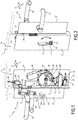
- an assembly 1 comprising a door 5 for access to a space 10, for example a toilet of a rail vehicle (not shown), a frame 15 of the door, and a locking system 20 Door.
- Door 5 is for example a manual hinged door. According to variants not shown, the door 5 is sliding, manual or automatic.
- the system 20 comprises a first frame 22 integrated into the door 5, a second frame 24 integrated into the frame 15, basic elements which will be detailed below, and selectively one or more optional modules also detailed below.
- the system 20 comprises, as a basic element, a first latch bolt 26, also called a first locking element, mounted on the first frame 22, an external opening member 28 for opening the door 5 from the outer side B, and an inner opener 30 for opening the door from the inner side A.
- the second frame 24 is located opposite the first frame 22.
- the first frame 22 and the second frame 24 have for example the general shape of a box.
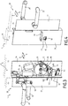
- the system 20 also comprises a deadbolt 32, also called a locking member, movable relative to the first frame 22 selectively between a locking position of the door 5 shown in the figures. figures 3 , 5 and 7 , and a rest position ( figure 1 ) authorizing the opening of the door.
- the system 20 further includes a locking button 34 located on the interior side A, to lock and unlock the door from the door. on the interior side, a first lock 36 located on the exterior side B for manually locking the door 5 from the exterior side, and a device 38 for mechanical slaving of the deadbolt 32 on the one hand to the locking button 34, and on the other hand , to the first lock 36.
- the system 20 finally comprises an exterior indicator 40 and an interior indicator 42 for displaying, respectively on the exterior side B and the interior side A, signs 44, 46 ( figures 1 and 2 ) and 48, 50 ( figures 3 and 4 ) visual and tactile, representative of the fact that the deadbolt 32 is in the locked position ( figure 3 ) or in the rest position ( figure 1 ) following an actuation of the locking button 34.
- the first latch bolt 26 is received in a keeper 52 of the second frame 24.
- the exterior opening member 28 and the interior opening member 30 are for example constituted by two handles structurally similar to one another.
- the external opening member 28 is adapted to actuate the first latch bolt 26 by means of a follower 54.
- the interior opening member 30 is adapted to actuate the first latch bolt 26 by means of a follower 56 also allowing it to actuate a second latch bolt 58, also called a second locking element, of which the role will be explained later.
- the external opening member 28 is not configured to actuate the second latch bolt 58.
- a second lock 59 is adapted to actuate the follower 56, that is to say to actuate the first latch bolt 26 and the second latch bolt 58.
- the second lock 59 is adapted to open manually door 5 from the exterior side B.
- the locking button 34 is movable between a rest position ( figure 2 ) in which the deadbolt 32 is itself in its rest position, and a locking position ( figure 4 ) in which the deadbolt itself is in its locked position ( figure 3 ).
- the first lock 36 is for example adapted to be actuated by a Bern key (not shown), that is to say a key defining a frustoconical housing with four faces.
- the first lock 36 is configured to allow the deadbolt 32 to be moved by means of such a key from its rest position to its locking position, and vice versa.
- the servo device 38 comprises for example a rocker 60 mounted to rotate relative to the second frame 24 and adapted to transform a rotational movement of the locking button 34 or of the first lock 36 into a movement of the dead bolt 32.
- the outer indicator 40 and the inner indicator 42 are for example formed respectively by the outer and inner faces of an element 62 mounted to rotate relative to the second frame 24 and integral in rotation with the locking button 34 and optionally with the first lock. 36.
- a window 43 ( figure 2 ) provided in the second frame 24 allows the interior indicator 42 to be seen.
- Another window (not shown) provided in the second frame 24 allows the exterior indicator 40 to be seen.
- the sign 44 is for example made up of a thick green circle carried by the outer face of the element 62. It goes without saying that the indicators, such as the sign 44, can be modified on demand, for example from the rail vehicle operator.
- the sign 46 is for example visually and tactilely similar to the sign 44, but is carried by the inner face of the element 62.
- the signs 48, 50 ( figures 3 and 4 ) consist for example of a red and thin circle and are respectively carried by the outer and inner faces of the element 62.
- Each of the optional modules present in the system 20 is fixed, preferably removably, on one of the first frame 22 or of the second frame 24.
- the first frame 22 and the second frame 24 are provided so that all the optional modules can first be attached to the assembly constituted by the first frame and the second frame, and so that the first frame and the second frame can then be fixed respectively on the door 5 and on the frame 15.
- a first optional module 64 is adapted to detect whether the door 5 is closed or open, and to send a first signal 66, for example electrical, representative of the fact that the door is closed or open.
- the first module 64 comprises a first sensor K1 fixed on the second frame 24 and adapted to detect whether the door is closed or open.
- the first sensor K1 is located on the first frame 22 to detect a translation of the latch bolt 26.
- a second optional module 68 is adapted to detect whether the deadbolt 32 is in the locked position or in the rest position, and to send a second signal 70, for example electrical, representative of the fact that the deadbolt is in the position. lock or in the rest position.
- the second module 68 comprises a second sensor K2 adapted to detect whether the deadbolt 32 is in the locking position or in the rest position.
- the second sensor K2 is for example fixed to the second frame 24.
- a third module 72 ( figure 5 ) optional is adapted to display on the exterior side B a sign 74 indicating whether the deadbolt 32 is in the locking position following an actuation of the first lock 36.
- the third module 72 ( figure 5 ) comprises a first support 76 mounted to rotate relative to the second frame 24 and adapted to be driven in rotation by the first lock 36.
- the first support 76 bears the sign 74 of the third module 72.
- the sign 74 is visual and tactile, and advantageously in the shape of a thick cross ( figure 5 ).
- a fourth optional module 78 ( figure 6 ) is adapted to display on the interior side A, a sign 80, visual and tactile, indicating whether the deadbolt 32 is in the locking position following an actuation of the first lock 36.
- the fourth module 78 comprises a second support 82 mounted rotary relative to the second frame 24 and adapted to be driven in rotation by the first lock 36.
- the second support 82 bears the sign 80, for example similar to the sign 74.
- a fifth optional module 84 ( figure 7 ) is adapted to receive a third locking signal 86, and to automatically lock the door on receipt of this signal.
- the fifth module 84 is also adapted so as not to oppose subsequently an opening of the door 5 by an actuation of the interior opening member 30.
- the fifth module 84 opposes an opening of the door from the exterior by actuation of the exterior opening member 28.
- the fifth module 84 comprises the second latch bolt 58, and an electric strike 88 mounted on the second frame 24 and adapted to receive the second latch bolt.
- the second latch bolt 58 is mechanically slaved to the interior opening member 30 by the follower 56 and independent of the exterior opening member 28.
- the electric strike 88 is movable between a removable configuration, in which it is movable relative to the second frame 24 to allow opening of the door 5 while the second latch bolt 58 is received in the electric strike, and a locked configuration , in which the electric strike is fixed relative to the second frame.
- An optional sixth module 90 ( figures 7 and 8 ) is adapted to display on the inside A a visual and tactile sign, which is, in the example shown, the sign 80 of the fourth module 78, to indicate whether the door 5 is automatically condemned following an action of the fifth module 84.
- the sixth module 90 comprises a third support 92 rotatably mounted relative to the second frame 24 and bearing on the side inside A the sign of the sixth module 90, and an actuator 94 adapted to move the third support 92 in rotation.
- a seventh optional module 96 ( figure 7 ) is adapted to display on the exterior side B a visual and tactile sign indicating whether the door 5 is condemned consecutively to an action of the fifth module 84.
- the seventh module 96 comprises a fourth support 98 mounted to rotate relative to the second frame 24 and carrying outer side B the sign of the seventh module, and the actuator 94 which is also suitable for moving the fourth support 98.
- An optional eighth module 100 ( figure 7 ) is suitable for detecting whether the door 5 is locked by manual actuation of the first lock 36, and for sending a fourth signal 102 representative of the state of the door.
- the eighth module 100 comprises a third sensor K3 adapted to detect whether the first lock 36 has been actuated, and to produce the fourth signal 102.
- the comparison of the fourth signal 102 and the signal 86 makes it possible to determine whether the door 5 has been manually locked. , automatically, or even manually and automatically (case shown on the figure 7 ).
- a ninth optional module 104 ( figure 1 ) is adapted to send a fifth sound signal 106 and representative of the fact that the door 5 is closed, locked, automatically condemned following an action of the fifth module 84, or manually condemned by an actuation of the first lock 36.
- the fifth signal 106 is intended to be perceptible by an operator endowed with normal hearing on the inside A and on the outside B, for example about two meters from the door 5.
- the ninth module 104 comprises an audible warning device 108, such as a loudspeaker, adapted to emit the fifth signal 106 according to the respective states of the first module 64, of the second module 68, of the fifth module 84 and of the eighth module 100.
- an audible warning device 108 such as a loudspeaker
- the optional modules are advantageously fixed using fasteners screwed, crimped, or welded in the frames 22 and 24, in predefined locations for these modules, such as those shown in the figures.
- the first module 64 makes it possible, thanks to the first sensor K1, to detect in which state the door 5 is located.
- the external indicator 40 ( figure 1 ) and internal indicator 42 ( figure 2 ) respectively display the signs 44 and 46 indicating that the door 5 has not been locked by an actuation of the locking button 34.
- a user can then enter the space 10, either directly if the door 5 is open, or by opening the door by actuating the external opening member 28. This possible actuation releases the first latch bolt 26 from the keeper. 52 and releases door 5.
- the electric strike 88 is in the removable configuration, that is to say it pivots relative to the second frame 24 so that the second latch bolt 58 does not prevent not opening the door 5.
- Actuation of the locking button 34 moves the deadbolt 32 into its locking position by virtue of the servo device 38.
- the balance 60 passes from the position shown on the figure 1 to the position shown on the figure 3 .
- the outer indicator 40 and the inner indicator 42 are moved and display the signs 48 and 50 ( figures 3 and 4 ) indicating that the door has been locked by a user.
- the door 5 can then be opened by actuating the interior opener 30.
- the user located in the space 10 can still open the door 5, because the interior opening member 30 acts on the possible second latch bolt 58 by removing it from the electric strike 88. In other words, even if the door 5 has been automatically locked by the fifth module 84, the user located inside the space 10 can open the door 5.
- an operator locks the door 5 manually by acting on the first lock 36. This moves the deadbolt 32 into its locking position by means of the servo device 38.
- This manual locking operation from the outer side B is reversible, either by an action of the operator again on the lock 36, or by an action of a user located in the space 10 on the locking button 34.
- the third module 72 displays on the outside B the sign 74 ( figure 5 ) indicating that the door has been locked manually.
- the fourth module 78 displays on the inside A the visual sign 82 ( figure 6 ) indicating this manual lockout.
- the signal 86 is sent to the fifth module 84.
- the electric strike 88 then passes from its removable configuration to its blocked configuration.
- the door 5 is locked as long as the second latch bolt 58 is not retracted, either by an action of a user on the interior opening member 30, or by an action of an operator on the second lock 59.
- the sixth module 90 when it is present displays on the inside A the sign 80 ( figure 8 ) and the seventh module 96 displays on the outer side B the visual sign 74 ( figure 7 ) to indicate the automatic door locking status.
- the eighth module 100 when it is present, detects whether the door 5 is locked by manual actuation of the first lock 36. This detection is advantageously made by comparing the measurement made by the third sensor K3 with the fact that the signal 86 was sent or not to the fifth module 84. This makes it possible to know the cause of the locking of the door.
- the ninth module 104 if present, sends the fifth signal 106 depending on the state of gate 5.
- the system 20 is of reduced cost, even in the presence of one or more of the optional modules.
- the first frame 22 and the second frame 24 make it possible to selectively receive one or more of the optional modules, and up to all the optional modules.
- the exterior opening member 28 and the interior opening member 30 are for example vertical handles, so that the force exerted for the translation of the sliding door is radial to the 'corresponding opening member.
- the first latch bolt 26, the second latch bolt 58 and the dead bolt 32 are, for example, hooks suitable for preventing the door from sliding when they are in the locked position.
- the electric strike 88 is then suitable for a sliding door.
Landscapes
- Engineering & Computer Science (AREA)
- Structural Engineering (AREA)
- Physics & Mathematics (AREA)
- Electromagnetism (AREA)
- Lock And Its Accessories (AREA)
Claims (11)
- System (20) zum Verriegeln einer Tür (5) für einen Zugang zu einem Raum (10), insbesondere einer Toilette eines Schienenfahrzeugs, wobei das System (20) aufweist einen ersten Rahmen (22), der vorgesehen ist, um in die Tür (5) integriert zu sein, und einen zweiten Rahmen (24), der vorgesehen ist, um in einen Rahmen (15) der Tür (5) integriert zu sein und sich gegenüber dem ersten Rahmen (22) zu befinden, wenn die Tür (5) geschlossen ist, wobei die geschlossene Tür (5) eine Innenseite (A) des Systems (20), die in Richtung zu dem Raum (10) gerichtet ist, und eine Außenseite (B), die entgegengesetzt zu dem Raum (10) gerichtet ist, definiert, wobei das System (20) ferner aufweist:- ein Verriegelungsmittel (32), das relativ zum ersten Rahmen (22) wahlweise zwischen einer Verriegelungsposition der Tür (5) und einer Ruheposition, die das Öffnen der Tür (5) erlaubt, bewegbar ist,- einen Verriegelungsknopf (34), der auf der Innenseite (A) angeordnet ist, ein erstes Schloss (36), das auf der Außenseite (B) angeordnet ist, und eine Vorrichtung (38) zum Steuern des Verriegelungsmittels (32) am Verriegelungsknopf (34) und am ersten Schloss (36), wobei das erste Schloss vorgesehen ist, um ein manuelles Verriegeln der Tür (5) von der Außenseite (B) aus zu ermöglichen, wobei der Verriegelungsknopf (34) vorgesehen ist, um ein Verriegeln und anschließendes Entriegeln der Tür (5) von der Innenseite (A) aus zu ermöglichen,- einen äußeren Anzeiger (40) und einen inneren Anzeiger (42), die angepasst sind, um auf der Außenseite (B) bzw. auf der Innenseite (A) visuelle (44, 46, 48, 50) und zum Beispiel taktile Zeichen anzuzeigen, die dafür repräsentativ sind, dass das Verriegelungsmittel (32) infolge einer Betätigung des Verriegelungsknopfes (34) in der Verriegelungsposition oder in der Ruheposition ist, und- ein erstes Verriegelungsmittel (26), das an dem ersten Rahmen (22) montiert ist, und ein äußeres Öffnungsmittel (28) und ein inneres Öffnungsmittel (30), die an dem ersten Rahmen (22) montiert sind, um das erste Verriegelungsmittel (26) von der Außenseite (B) bzw. von der Innenseite (A) aus zu betätigen,wobei das System (20) ferner wahlweise ein oder mehrere optionale Module aus den folgenden Modulen aufweist:- ein erstes Modul (64), das angepasst ist, um zu detektieren, ob die Tür (5) geschlossen oder offen ist, und um ein erstes elektrisches oder elektromagnetisches Signal (66) zu senden, das dafür repräsentativ ist, dass die Tür (5) geschlossen oder offen ist,- ein zweites Modul (68), das angepasst ist, um zu detektieren, ob das Verriegelungsmittel (32) in der Verriegelungsposition oder in der Ruheposition ist, und um ein zweites elektrisches oder elektromagnetisches Signal (70) zu senden, das dafür repräsentativ ist, dass das Verriegelungsmittel (32) in der Verriegelungsposition oder in der Ruheposition ist,- ein drittes Modul (72), das angepasst ist, um auf der Außenseite (B) ein visuelles und zum Beispiel taktiles Zeichen (74) anzuzeigen, das angibt, ob das Verriegelungsmittel (32) in Folge einer Betätigung des ersten Schlosses (36) in der Verriegelungsposition ist,- ein viertes Modul (78), das angepasst ist, um auf der Innenseite (A) ein visuelles und zum Beispiel taktiles Zeichen (80) anzuzeigen, das angibt, ob das Verriegelungsmittel (32) in Folge einer Betätigung des ersten Schlosses (36) in der Verriegelungsposition ist,- ein fünftes Modul (84), das angepasst ist, um ein drittes elektrisches Signal (86) zur Fernverriegelung der Tür (5) zu empfangen und um die Tür (5) bei Empfang des dritten Signals (86) automatisch zu verriegeln, wobei das fünfte Modul (84) im Anschluss nicht verhindert, dass die Tür (5) durch eine Betätigung des inneren Öffnungsmittels (30) geöffnet wird,- ein sechstes Modul (90), das angepasst ist, um auf der Innenseite (A) ein visuelles und zum Beispiel taktiles Zeichen (80) anzuzeigen, das angibt, ob die Tür (5) in Folge einer Aktion des fünften Moduls (84) verriegelt ist,- ein siebtes Modul (96), das angepasst ist, um auf der Außenseite (B) ein visuelles und zum Beispiel taktiles Zeichen (74) anzuzeigen, das angibt, ob die Tür (5) in Folge einer Aktion des fünften Moduls (84) verriegelt ist,- ein achtes Modul (100), das angepasst ist, um zu detektieren, ob die Tür (5) durch eine manuelle Betätigung des ersten Schlosses (36) verriegelt ist, und um ein viertes repräsentatives elektrisches oder elektromagnetisches Signal (102) zu senden, und- ein neuntes Modul (104), das angepasst ist, um ein fünftes Tonsignal (106) zu senden, das dafür repräsentativ ist, dass die Tür (5) in der Besetzt-Position durch eine Betätigung des Verriegelungsknopfes (34) verriegelt ist, automatisch in Folge einer Aktion des fünften Moduls (84) verriegelt ist oder manuell durch eine Betätigung des ersten Schlosses (36) verriegelt ist, wobei das fünfte Signal (106) vorgesehen ist, um von einer Bedienperson oder einem Fahrgast auf der Innenseite (A) und auf der Außenseite (B) wahrgenommen zu werden,wobei jedes der vorhandenen optionalen Module an einem von dem ersten Rahmen (22) oder dem zweiten Rahmen (24) vorzugsweise lösbar befestigt ist,
und wobei der erste Rahmen (22) und der zweite Rahmen (24) so vorgesehen sind, dass alle optionalen Module zunächst an der durch den ersten Rahmen (22) und den zweiten Rahmen (24) gebildeten Baugruppe befestigt werden können, und dass der erste Rahmen (22) und der zweite Rahmen (24) anschließend an der Tür (5) bzw. an dem Rahmen (15) befestigt werden können. - System (20) gemäß Anspruch 1, wobei das erste Modul (64) einen ersten Sensor (K1) aufweist, der angepasst ist, um zu detektieren, ob die Tür (5) geschlossen oder offen ist, wobei der erste Sensor (K1) in einem ersten Schließblech (52) des zweiten Rahmens (24), das vorgesehen ist, um das erste Verriegelungselement (26) aufzunehmen, oder an dem ersten Rahmen (22) befestigt ist.
- System (20) gemäß Anspruch 1 oder 2, wobei das zweite Modul (68) einen zweiten Sensor (K2) aufweist, der angepasst ist, um zu detektieren, ob das Verriegelungsmittel (32) in der Verriegelungsposition oder in der Ruheposition ist, wobei der zweite Sensor (K2) an einem von dem ersten Rahmen (22) und dem zweiten Rahmen (24) befestigt ist.
- System (20) gemäß irgendeinem der Ansprüche 1 bis 3, wobei das dritte Modul (72) einen ersten Träger (76), vorzugsweise eine Scheibe, aufweist, der/die relativ zum ersten Rahmen (22) oder zum zweiten Rahmen (24) drehbar gelagert ist, wobei der erste Träger (76) angepasst ist, um durch das erste Schloss (36) angetrieben zu werden, wobei der erste Träger (76) das Zeichen (74) des dritten Moduls (72) trägt.
- System (20) gemäß irgendeinem der Ansprüche 1 bis 4, wobei das vierte Modul (78) einen zweiten Träger (82), vorzugsweise eine Scheibe, aufweist, der/die relativ zu dem ersten Rahmen (22) oder zu dem zweiten Rahmen (24) drehbar gelagert ist, wobei der zweite Träger (82) angepasst ist, um durch das erste Schloss (36) angetrieben zu werden, wobei der zweite Träger (82) das Zeichen (80) des vierten Moduls (78) trägt.
- System (20) gemäß irgendeinem der Ansprüche 1 bis 5, wobei das fünfte Modul (84) ein zweites Verriegelungselement (58), das bewegbar an dem ersten Rahmen (22) montiert ist, und ein elektrisches Schließblech (88) aufweist, das an dem zweiten Rahmen (24) montiert ist und angepasst ist, um das zweite Verriegelungselement (58) aufzunehmen, wobei das zweite Verriegelungselement von dem inneren Öffnungselement (30) gesteuert und unabhängig von dem äußeren Öffnungselement (28) ist, wobei das elektrische Schließblech (88) bewegbar ist zwischen einer Löse-Konfiguration, in der das elektrische Schließblech (88) relativ zu dem zweiten Rahmen (24) bewegbar ist, um ein Öffnen der Tür (5) zu ermöglichen, während das zweite Verriegelungselement (58) in dem elektrischen Schließblech (88) aufgenommen ist, und einer Blockier-Konfiguration, in der das elektrische Schließblech (88) relativ zu dem zweiten Rahmen (24) fixiert ist.
- System (20) gemäß Anspruch 6, wobei das fünfte Modul (84) ferner ein zweites Schloss (59) aufweist, das an der Außenseite (B) des ersten Rahmens (22) montiert und angepasst ist, um das zweite Verriegelungselement (58) zu betätigen, wobei das zweite Schloss (59) vorgesehen ist, um ein manuelles Öffnen der Tür (5) nach dem automatischen Verriegeln der Tür (5) zu ermöglichen.
- System (20) gemäß irgendeinem der Ansprüche 1 bis 7, wobei das sechste Modul (90) einen dritten Träger (92), vorzugsweise eine Scheibe, der/die relativ zu dem ersten Rahmen (22) oder zu dem zweiten Rahmen (24) drehbar gelagert ist, und einen Aktuator (94) aufweist, der angepasst ist, um den dritten Träger (92) drehbar zu bewegen, wobei der dritte Träger (92) auf einer Innenseite (A) das Zeichen des sechsten Moduls (90) trägt.
- System (20) gemäß irgendeinem der Ansprüche 1 bis 8, wobei das siebte Modul (96) einen vierten Träger (98), vorzugsweise eine Scheibe, der/die relativ zu dem ersten Rahmen (22) oder zu dem zweiten Rahmen (24) drehbar gelagert ist, und einen Aktuator (94) aufweist, der angepasst ist, um den vierten Träger (98) drehbar zu bewegen, wobei der vierte Träger (98) auf einer Außenseite (B) das Zeichen (74) des siebten Moduls (96) trägt.
- System (20) gemäß irgendeinem der Ansprüche 1 bis 9, wobei das achte Modul (100) einen dritten Sensor (K3) aufweist, der angepasst ist, um zu detektieren, ob das erste Schloss (36) betätigt wurde, und um das vierte Signal (102) zu erzeugen.
- System (20) gemäß irgendeinem der Ansprüche 1 bis 10, wobei das neunte Modul (104) eine Ton-Warnvorrichtung (108) oder eine Vibrationsvorrichtung aufweist, die angepasst ist, um das fünfte Signal (106) in Abhängigkeit von jeweiligen Zuständen des ersten Moduls (64), des zweiten Moduls (68), des fünften Moduls (84) und des achten Moduls (100) zu emittieren.
Applications Claiming Priority (1)
| Application Number | Priority Date | Filing Date | Title |
|---|---|---|---|
| FR1753217A FR3065245B1 (fr) | 2017-04-12 | 2017-04-12 | Systeme de verrouillage d'une porte d'acces a un espace, notamment des toilettes d'un vehicule ferroviaire |
Publications (2)
| Publication Number | Publication Date |
|---|---|
| EP3388603A1 EP3388603A1 (de) | 2018-10-17 |
| EP3388603B1 true EP3388603B1 (de) | 2021-06-09 |
Family
ID=59031192
Family Applications (1)
| Application Number | Title | Priority Date | Filing Date |
|---|---|---|---|
| EP18166875.7A Active EP3388603B1 (de) | 2017-04-12 | 2018-04-11 | Verriegelungssystem einer zugangstür zu einem raum, insbesondere von toiletten eines schienenfahrzeugs |
Country Status (2)
| Country | Link |
|---|---|
| EP (1) | EP3388603B1 (de) |
| FR (1) | FR3065245B1 (de) |
Families Citing this family (1)
| Publication number | Priority date | Publication date | Assignee | Title |
|---|---|---|---|---|
| FR3087808B1 (fr) * | 2018-10-26 | 2020-11-06 | Sncf Mobilites | Systeme et procede de condamnation de l'acces a un compartiment privatisable, notamment un sanitaire |
Family Cites Families (5)
| Publication number | Priority date | Publication date | Assignee | Title |
|---|---|---|---|---|
| GB191424308A (en) * | 1914-12-18 | 1915-07-15 | Samuel Rowland Parkes | Improvements in Latches. |
| GB191513609A (en) * | 1914-12-18 | 1916-06-15 | Samuel Rowland Parkes | Improvements in Latches. |
| DE69925018T2 (de) * | 1998-11-03 | 2006-01-19 | Azoteq (Proprietary) Ltd. | Elektrisches schloss |
| DE102013200156A1 (de) * | 2013-01-08 | 2014-07-10 | Hewi Heinrich Wilke Gmbh | Beschlaganordnung |
| FR3025822B1 (fr) * | 2014-09-17 | 2016-12-09 | Alstom Transp Tech | Dispositif perfectionne de verrouillage d'une porte, notamment d'une porte de cabine de toilette de vehicule ferroviaire |
-
2017
- 2017-04-12 FR FR1753217A patent/FR3065245B1/fr not_active Expired - Fee Related
-
2018
- 2018-04-11 EP EP18166875.7A patent/EP3388603B1/de active Active
Non-Patent Citations (1)
| Title |
|---|
| None * |
Also Published As
| Publication number | Publication date |
|---|---|
| EP3388603A1 (de) | 2018-10-17 |
| FR3065245A1 (fr) | 2018-10-19 |
| FR3065245B1 (fr) | 2019-07-05 |
Similar Documents
| Publication | Publication Date | Title |
|---|---|---|
| EP3388602B1 (de) | Modulsystem zur verriegelung einer zugangstür zu einem raum mit umkehrbaren elementen | |
| EP3456579A1 (de) | Gleitschiene für fahrzeugsitz, und fahrzeugsitz, der eine solche gleitschiene umfasst | |
| EP3388601B1 (de) | Verriegelungssystem einer zugangstür zu einem raum, insbesondere von toiletten eines schienenfahrzeugs | |
| EP2998474B1 (de) | Perfektionierte verriegelungsvorrichtung für eine tür, insbesondere einer toilettenkabinentür eines schienenfahrzeugs | |
| EP2303651A1 (de) | Befestigungshalterung zur montage eines geräts auf einem flugzeugfahrwerk, verwendung einer derartigen befestigungshalterung sowie anordnung mit einem überwachungsgerät und einer derartigen befestigungshalterung | |
| FR2652375A1 (fr) | Serrure de securite. | |
| EP3388603B1 (de) | Verriegelungssystem einer zugangstür zu einem raum, insbesondere von toiletten eines schienenfahrzeugs | |
| FR2995622A1 (fr) | Came de transformation du mouvement d'un pene | |
| FR2931185A1 (fr) | Systeme et procede de fermeture motorise pour ouvrant de vehicule avec joint compressible | |
| EP1845054A1 (de) | Vorrichtung zur Verriegelung eines ausfallsicheren Schlosses, insbesondere für eine Etagentür eines Aufzugs, und diese Vorrichtung enthaltendes Schloss | |
| EP3388604A1 (de) | Verriegelungssystem einer zugangstür zu einem raum, insbesondere toiletten in einem schienenfahrzeug | |
| EP1404605A1 (de) | Verriegelungsvorrichtung für schachttür mit unabhängiger notentriegelungsvorrichtung | |
| EP3388600B1 (de) | Verriegelungssystem einer tür | |
| EP2821570B1 (de) | Türschlossvorrichtung, insbesondere für wc-raum, z.b. für eisenbahnfahrzeug | |
| EP1460018A1 (de) | Steuerung für das Notentriegelungsgerät einer Aufzugsschachttür | |
| WO2013167308A1 (fr) | Ensemble de verrouillage avec serrure electromagnetique et serrure mecanique | |
| EP3887627B1 (de) | System zum entriegeln des zugangs zu einem verriegelbaren fach, insbesondere einer badezimmerarmatur | |
| EP3870783B1 (de) | System und verfahren zur verhinderung des zugangs zu einem verriegelbaren fach, insbesondere einer sanitärarmatur | |
| FR3025235A1 (fr) | Dispositif d'indication, organe d'information pour un tel dispositif et systeme de verrouillage comprenant un tel dispositif | |
| EP2896771B1 (de) | Perfektioniertes Schloss mit Doppelzylinder | |
| FR2662734A1 (fr) | Serrure decondamnable a distance. | |
| EP0898037B1 (de) | Motorischer Stellantrieb mit Fernsteuerung für ein Garagentor | |
| FR2634812A1 (fr) | Dispositif de fermeture anti-panique | |
| FR2856099A1 (fr) | Dispositif de transfert de valeurs | |
| FR2998701A1 (fr) | Dispositif a rideau metallique pour systemes de prelevement automatique d'argent comptant (atm) et methode de gestion correspondante |
Legal Events
| Date | Code | Title | Description |
|---|---|---|---|
| PUAI | Public reference made under article 153(3) epc to a published international application that has entered the european phase |
Free format text: ORIGINAL CODE: 0009012 |
|
| STAA | Information on the status of an ep patent application or granted ep patent |
Free format text: STATUS: THE APPLICATION HAS BEEN PUBLISHED |
|
| AK | Designated contracting states |
Kind code of ref document: A1 Designated state(s): AL AT BE BG CH CY CZ DE DK EE ES FI FR GB GR HR HU IE IS IT LI LT LU LV MC MK MT NL NO PL PT RO RS SE SI SK SM TR |
|
| AX | Request for extension of the european patent |
Extension state: BA ME |
|
| STAA | Information on the status of an ep patent application or granted ep patent |
Free format text: STATUS: REQUEST FOR EXAMINATION WAS MADE |
|
| 17P | Request for examination filed |
Effective date: 20190325 |
|
| RBV | Designated contracting states (corrected) |
Designated state(s): AL AT BE BG CH CY CZ DE DK EE ES FI FR GB GR HR HU IE IS IT LI LT LU LV MC MK MT NL NO PL PT RO RS SE SI SK SM TR |
|
| GRAP | Despatch of communication of intention to grant a patent |
Free format text: ORIGINAL CODE: EPIDOSNIGR1 |
|
| STAA | Information on the status of an ep patent application or granted ep patent |
Free format text: STATUS: GRANT OF PATENT IS INTENDED |
|
| GRAJ | Information related to disapproval of communication of intention to grant by the applicant or resumption of examination proceedings by the epo deleted |
Free format text: ORIGINAL CODE: EPIDOSDIGR1 |
|
| GRAP | Despatch of communication of intention to grant a patent |
Free format text: ORIGINAL CODE: EPIDOSNIGR1 |
|
| INTG | Intention to grant announced |
Effective date: 20201112 |
|
| INTG | Intention to grant announced |
Effective date: 20201120 |
|
| GRAS | Grant fee paid |
Free format text: ORIGINAL CODE: EPIDOSNIGR3 |
|
| GRAA | (expected) grant |
Free format text: ORIGINAL CODE: 0009210 |
|
| STAA | Information on the status of an ep patent application or granted ep patent |
Free format text: STATUS: THE PATENT HAS BEEN GRANTED |
|
| AK | Designated contracting states |
Kind code of ref document: B1 Designated state(s): AL AT BE BG CH CY CZ DE DK EE ES FI FR GB GR HR HU IE IS IT LI LT LU LV MC MK MT NL NO PL PT RO RS SE SI SK SM TR |
|
| REG | Reference to a national code |
Ref country code: GB Ref legal event code: FG4D Free format text: NOT ENGLISH |
|
| REG | Reference to a national code |
Ref country code: CH Ref legal event code: EP Ref country code: AT Ref legal event code: REF Ref document number: 1400644 Country of ref document: AT Kind code of ref document: T Effective date: 20210615 |
|
| REG | Reference to a national code |
Ref country code: DE Ref legal event code: R096 Ref document number: 602018018236 Country of ref document: DE |
|
| REG | Reference to a national code |
Ref country code: IE Ref legal event code: FG4D Free format text: LANGUAGE OF EP DOCUMENT: FRENCH |
|
| REG | Reference to a national code |
Ref country code: LT Ref legal event code: MG9D |
|
| PG25 | Lapsed in a contracting state [announced via postgrant information from national office to epo] |
Ref country code: HR Free format text: LAPSE BECAUSE OF FAILURE TO SUBMIT A TRANSLATION OF THE DESCRIPTION OR TO PAY THE FEE WITHIN THE PRESCRIBED TIME-LIMIT Effective date: 20210609 Ref country code: LT Free format text: LAPSE BECAUSE OF FAILURE TO SUBMIT A TRANSLATION OF THE DESCRIPTION OR TO PAY THE FEE WITHIN THE PRESCRIBED TIME-LIMIT Effective date: 20210609 Ref country code: FI Free format text: LAPSE BECAUSE OF FAILURE TO SUBMIT A TRANSLATION OF THE DESCRIPTION OR TO PAY THE FEE WITHIN THE PRESCRIBED TIME-LIMIT Effective date: 20210609 Ref country code: BG Free format text: LAPSE BECAUSE OF FAILURE TO SUBMIT A TRANSLATION OF THE DESCRIPTION OR TO PAY THE FEE WITHIN THE PRESCRIBED TIME-LIMIT Effective date: 20210909 |
|
| REG | Reference to a national code |
Ref country code: AT Ref legal event code: MK05 Ref document number: 1400644 Country of ref document: AT Kind code of ref document: T Effective date: 20210609 |
|
| REG | Reference to a national code |
Ref country code: NL Ref legal event code: MP Effective date: 20210609 |
|
| PG25 | Lapsed in a contracting state [announced via postgrant information from national office to epo] |
Ref country code: GR Free format text: LAPSE BECAUSE OF FAILURE TO SUBMIT A TRANSLATION OF THE DESCRIPTION OR TO PAY THE FEE WITHIN THE PRESCRIBED TIME-LIMIT Effective date: 20210910 Ref country code: RS Free format text: LAPSE BECAUSE OF FAILURE TO SUBMIT A TRANSLATION OF THE DESCRIPTION OR TO PAY THE FEE WITHIN THE PRESCRIBED TIME-LIMIT Effective date: 20210609 Ref country code: SE Free format text: LAPSE BECAUSE OF FAILURE TO SUBMIT A TRANSLATION OF THE DESCRIPTION OR TO PAY THE FEE WITHIN THE PRESCRIBED TIME-LIMIT Effective date: 20210609 Ref country code: NO Free format text: LAPSE BECAUSE OF FAILURE TO SUBMIT A TRANSLATION OF THE DESCRIPTION OR TO PAY THE FEE WITHIN THE PRESCRIBED TIME-LIMIT Effective date: 20210909 Ref country code: LV Free format text: LAPSE BECAUSE OF FAILURE TO SUBMIT A TRANSLATION OF THE DESCRIPTION OR TO PAY THE FEE WITHIN THE PRESCRIBED TIME-LIMIT Effective date: 20210609 |
|
| PG25 | Lapsed in a contracting state [announced via postgrant information from national office to epo] |
Ref country code: SK Free format text: LAPSE BECAUSE OF FAILURE TO SUBMIT A TRANSLATION OF THE DESCRIPTION OR TO PAY THE FEE WITHIN THE PRESCRIBED TIME-LIMIT Effective date: 20210609 Ref country code: SM Free format text: LAPSE BECAUSE OF FAILURE TO SUBMIT A TRANSLATION OF THE DESCRIPTION OR TO PAY THE FEE WITHIN THE PRESCRIBED TIME-LIMIT Effective date: 20210609 Ref country code: ES Free format text: LAPSE BECAUSE OF FAILURE TO SUBMIT A TRANSLATION OF THE DESCRIPTION OR TO PAY THE FEE WITHIN THE PRESCRIBED TIME-LIMIT Effective date: 20210609 Ref country code: EE Free format text: LAPSE BECAUSE OF FAILURE TO SUBMIT A TRANSLATION OF THE DESCRIPTION OR TO PAY THE FEE WITHIN THE PRESCRIBED TIME-LIMIT Effective date: 20210609 Ref country code: PT Free format text: LAPSE BECAUSE OF FAILURE TO SUBMIT A TRANSLATION OF THE DESCRIPTION OR TO PAY THE FEE WITHIN THE PRESCRIBED TIME-LIMIT Effective date: 20211011 Ref country code: NL Free format text: LAPSE BECAUSE OF FAILURE TO SUBMIT A TRANSLATION OF THE DESCRIPTION OR TO PAY THE FEE WITHIN THE PRESCRIBED TIME-LIMIT Effective date: 20210609 Ref country code: RO Free format text: LAPSE BECAUSE OF FAILURE TO SUBMIT A TRANSLATION OF THE DESCRIPTION OR TO PAY THE FEE WITHIN THE PRESCRIBED TIME-LIMIT Effective date: 20210609 Ref country code: AT Free format text: LAPSE BECAUSE OF FAILURE TO SUBMIT A TRANSLATION OF THE DESCRIPTION OR TO PAY THE FEE WITHIN THE PRESCRIBED TIME-LIMIT Effective date: 20210609 Ref country code: CZ Free format text: LAPSE BECAUSE OF FAILURE TO SUBMIT A TRANSLATION OF THE DESCRIPTION OR TO PAY THE FEE WITHIN THE PRESCRIBED TIME-LIMIT Effective date: 20210609 |
|
| PG25 | Lapsed in a contracting state [announced via postgrant information from national office to epo] |
Ref country code: PL Free format text: LAPSE BECAUSE OF FAILURE TO SUBMIT A TRANSLATION OF THE DESCRIPTION OR TO PAY THE FEE WITHIN THE PRESCRIBED TIME-LIMIT Effective date: 20210609 |
|
| REG | Reference to a national code |
Ref country code: DE Ref legal event code: R097 Ref document number: 602018018236 Country of ref document: DE |
|
| PLBE | No opposition filed within time limit |
Free format text: ORIGINAL CODE: 0009261 |
|
| STAA | Information on the status of an ep patent application or granted ep patent |
Free format text: STATUS: NO OPPOSITION FILED WITHIN TIME LIMIT |
|
| PG25 | Lapsed in a contracting state [announced via postgrant information from national office to epo] |
Ref country code: DK Free format text: LAPSE BECAUSE OF FAILURE TO SUBMIT A TRANSLATION OF THE DESCRIPTION OR TO PAY THE FEE WITHIN THE PRESCRIBED TIME-LIMIT Effective date: 20210609 |
|
| 26N | No opposition filed |
Effective date: 20220310 |
|
| PG25 | Lapsed in a contracting state [announced via postgrant information from national office to epo] |
Ref country code: AL Free format text: LAPSE BECAUSE OF FAILURE TO SUBMIT A TRANSLATION OF THE DESCRIPTION OR TO PAY THE FEE WITHIN THE PRESCRIBED TIME-LIMIT Effective date: 20210609 |
|
| REG | Reference to a national code |
Ref country code: CH Ref legal event code: PL |
|
| GBPC | Gb: european patent ceased through non-payment of renewal fee |
Effective date: 20220411 |
|
| REG | Reference to a national code |
Ref country code: BE Ref legal event code: MM Effective date: 20220430 |
|
| PG25 | Lapsed in a contracting state [announced via postgrant information from national office to epo] |
Ref country code: MC Free format text: LAPSE BECAUSE OF FAILURE TO SUBMIT A TRANSLATION OF THE DESCRIPTION OR TO PAY THE FEE WITHIN THE PRESCRIBED TIME-LIMIT Effective date: 20210609 Ref country code: LU Free format text: LAPSE BECAUSE OF NON-PAYMENT OF DUE FEES Effective date: 20220411 Ref country code: LI Free format text: LAPSE BECAUSE OF NON-PAYMENT OF DUE FEES Effective date: 20220430 Ref country code: GB Free format text: LAPSE BECAUSE OF NON-PAYMENT OF DUE FEES Effective date: 20220411 Ref country code: CH Free format text: LAPSE BECAUSE OF NON-PAYMENT OF DUE FEES Effective date: 20220430 |
|
| PG25 | Lapsed in a contracting state [announced via postgrant information from national office to epo] |
Ref country code: BE Free format text: LAPSE BECAUSE OF NON-PAYMENT OF DUE FEES Effective date: 20220430 |
|
| PG25 | Lapsed in a contracting state [announced via postgrant information from national office to epo] |
Ref country code: IE Free format text: LAPSE BECAUSE OF NON-PAYMENT OF DUE FEES Effective date: 20220411 |
|
| P01 | Opt-out of the competence of the unified patent court (upc) registered |
Effective date: 20230823 |
|
| PG25 | Lapsed in a contracting state [announced via postgrant information from national office to epo] |
Ref country code: HU Free format text: LAPSE BECAUSE OF FAILURE TO SUBMIT A TRANSLATION OF THE DESCRIPTION OR TO PAY THE FEE WITHIN THE PRESCRIBED TIME-LIMIT; INVALID AB INITIO Effective date: 20180411 |
|
| PG25 | Lapsed in a contracting state [announced via postgrant information from national office to epo] |
Ref country code: MK Free format text: LAPSE BECAUSE OF FAILURE TO SUBMIT A TRANSLATION OF THE DESCRIPTION OR TO PAY THE FEE WITHIN THE PRESCRIBED TIME-LIMIT Effective date: 20210609 Ref country code: CY Free format text: LAPSE BECAUSE OF FAILURE TO SUBMIT A TRANSLATION OF THE DESCRIPTION OR TO PAY THE FEE WITHIN THE PRESCRIBED TIME-LIMIT Effective date: 20210609 |
|
| PG25 | Lapsed in a contracting state [announced via postgrant information from national office to epo] |
Ref country code: MT Free format text: LAPSE BECAUSE OF FAILURE TO SUBMIT A TRANSLATION OF THE DESCRIPTION OR TO PAY THE FEE WITHIN THE PRESCRIBED TIME-LIMIT Effective date: 20210609 |
|
| PGFP | Annual fee paid to national office [announced via postgrant information from national office to epo] |
Ref country code: DE Payment date: 20250422 Year of fee payment: 8 |
|
| PGFP | Annual fee paid to national office [announced via postgrant information from national office to epo] |
Ref country code: IT Payment date: 20250424 Year of fee payment: 8 |
|
| PGFP | Annual fee paid to national office [announced via postgrant information from national office to epo] |
Ref country code: FR Payment date: 20250425 Year of fee payment: 8 |
|
| PG25 | Lapsed in a contracting state [announced via postgrant information from national office to epo] |
Ref country code: TR Free format text: LAPSE BECAUSE OF FAILURE TO SUBMIT A TRANSLATION OF THE DESCRIPTION OR TO PAY THE FEE WITHIN THE PRESCRIBED TIME-LIMIT Effective date: 20210609 |