EP3388731A1 - Module d'éclairage et véhicule automobile equipé avec un tel module - Google Patents
Module d'éclairage et véhicule automobile equipé avec un tel module Download PDFInfo
- Publication number
- EP3388731A1 EP3388731A1 EP17165713.3A EP17165713A EP3388731A1 EP 3388731 A1 EP3388731 A1 EP 3388731A1 EP 17165713 A EP17165713 A EP 17165713A EP 3388731 A1 EP3388731 A1 EP 3388731A1
- Authority
- EP
- European Patent Office
- Prior art keywords
- optical element
- light
- light source
- mechanically deformable
- oled
- Prior art date
- Legal status (The legal status is an assumption and is not a legal conclusion. Google has not performed a legal analysis and makes no representation as to the accuracy of the status listed.)
- Withdrawn
Links
- 230000003287 optical effect Effects 0.000 claims abstract description 103
- 238000009826 distribution Methods 0.000 claims abstract description 45
- 230000008859 change Effects 0.000 claims abstract description 9
- 230000005855 radiation Effects 0.000 claims description 6
- 239000011888 foil Substances 0.000 claims description 2
- 238000007493 shaping process Methods 0.000 abstract 1
- 230000006870 function Effects 0.000 description 95
- 241000219739 Lens Species 0.000 description 48
- 230000003044 adaptive effect Effects 0.000 description 29
- 230000005283 ground state Effects 0.000 description 16
- 239000000463 material Substances 0.000 description 7
- 238000005452 bending Methods 0.000 description 6
- 230000008901 benefit Effects 0.000 description 6
- 238000005538 encapsulation Methods 0.000 description 6
- 230000009471 action Effects 0.000 description 5
- 239000004020 conductor Substances 0.000 description 5
- 239000010408 film Substances 0.000 description 5
- 239000004065 semiconductor Substances 0.000 description 5
- 239000000758 substrate Substances 0.000 description 5
- 230000004913 activation Effects 0.000 description 4
- 239000013078 crystal Substances 0.000 description 4
- 238000004519 manufacturing process Methods 0.000 description 4
- 238000006243 chemical reaction Methods 0.000 description 3
- 239000003086 colorant Substances 0.000 description 3
- 230000006835 compression Effects 0.000 description 3
- 238000007906 compression Methods 0.000 description 3
- 238000005516 engineering process Methods 0.000 description 3
- 238000005286 illumination Methods 0.000 description 3
- 239000000243 solution Substances 0.000 description 3
- 230000000007 visual effect Effects 0.000 description 3
- 206010039203 Road traffic accident Diseases 0.000 description 2
- 230000015572 biosynthetic process Effects 0.000 description 2
- 238000012937 correction Methods 0.000 description 2
- 238000001514 detection method Methods 0.000 description 2
- 230000000694 effects Effects 0.000 description 2
- 230000005670 electromagnetic radiation Effects 0.000 description 2
- 230000007613 environmental effect Effects 0.000 description 2
- 239000012530 fluid Substances 0.000 description 2
- 238000001093 holography Methods 0.000 description 2
- 230000006872 improvement Effects 0.000 description 2
- 230000001795 light effect Effects 0.000 description 2
- 239000003550 marker Substances 0.000 description 2
- 230000008447 perception Effects 0.000 description 2
- 239000004033 plastic Substances 0.000 description 2
- 239000002096 quantum dot Substances 0.000 description 2
- 230000002441 reversible effect Effects 0.000 description 2
- 239000010409 thin film Substances 0.000 description 2
- DGAQECJNVWCQMB-PUAWFVPOSA-M Ilexoside XXIX Chemical compound C[C@@H]1CC[C@@]2(CC[C@@]3(C(=CC[C@H]4[C@]3(CC[C@@H]5[C@@]4(CC[C@@H](C5(C)C)OS(=O)(=O)[O-])C)C)[C@@H]2[C@]1(C)O)C)C(=O)O[C@H]6[C@@H]([C@H]([C@@H]([C@H](O6)CO)O)O)O.[Na+] DGAQECJNVWCQMB-PUAWFVPOSA-M 0.000 description 1
- 240000004322 Lens culinaris Species 0.000 description 1
- 230000001133 acceleration Effects 0.000 description 1
- 230000003213 activating effect Effects 0.000 description 1
- 238000004458 analytical method Methods 0.000 description 1
- QVGXLLKOCUKJST-UHFFFAOYSA-N atomic oxygen Chemical compound [O] QVGXLLKOCUKJST-UHFFFAOYSA-N 0.000 description 1
- 239000000969 carrier Substances 0.000 description 1
- 239000011248 coating agent Substances 0.000 description 1
- 238000000576 coating method Methods 0.000 description 1
- 238000004590 computer program Methods 0.000 description 1
- 230000009849 deactivation Effects 0.000 description 1
- 230000001419 dependent effect Effects 0.000 description 1
- 238000013461 design Methods 0.000 description 1
- 238000011982 device technology Methods 0.000 description 1
- 230000005520 electrodynamics Effects 0.000 description 1
- 239000008393 encapsulating agent Substances 0.000 description 1
- 230000004907 flux Effects 0.000 description 1
- 239000007789 gas Substances 0.000 description 1
- 230000004313 glare Effects 0.000 description 1
- 239000010720 hydraulic oil Substances 0.000 description 1
- 238000001746 injection moulding Methods 0.000 description 1
- 230000010354 integration Effects 0.000 description 1
- 230000003993 interaction Effects 0.000 description 1
- 238000011835 investigation Methods 0.000 description 1
- 239000007788 liquid Substances 0.000 description 1
- 238000005259 measurement Methods 0.000 description 1
- 238000000034 method Methods 0.000 description 1
- 238000002156 mixing Methods 0.000 description 1
- 239000000203 mixture Substances 0.000 description 1
- 238000012986 modification Methods 0.000 description 1
- 230000004048 modification Effects 0.000 description 1
- 238000012544 monitoring process Methods 0.000 description 1
- 230000007935 neutral effect Effects 0.000 description 1
- 239000001301 oxygen Substances 0.000 description 1
- 229910052760 oxygen Inorganic materials 0.000 description 1
- 230000002093 peripheral effect Effects 0.000 description 1
- 229920001296 polysiloxane Polymers 0.000 description 1
- 238000003825 pressing Methods 0.000 description 1
- 230000035484 reaction time Effects 0.000 description 1
- 230000004044 response Effects 0.000 description 1
- 230000009131 signaling function Effects 0.000 description 1
- 229910052708 sodium Inorganic materials 0.000 description 1
- 239000011734 sodium Substances 0.000 description 1
- 239000007787 solid Substances 0.000 description 1
- 239000013589 supplement Substances 0.000 description 1
- 230000008719 thickening Effects 0.000 description 1
- 230000007704 transition Effects 0.000 description 1
- 230000004304 visual acuity Effects 0.000 description 1
- XLYOFNOQVPJJNP-UHFFFAOYSA-N water Substances O XLYOFNOQVPJJNP-UHFFFAOYSA-N 0.000 description 1
Images


Classifications
-
- F—MECHANICAL ENGINEERING; LIGHTING; HEATING; WEAPONS; BLASTING
- F21—LIGHTING
- F21S—NON-PORTABLE LIGHTING DEVICES; SYSTEMS THEREOF; VEHICLE LIGHTING DEVICES SPECIALLY ADAPTED FOR VEHICLE EXTERIORS
- F21S43/00—Signalling devices specially adapted for vehicle exteriors, e.g. brake lamps, direction indicator lights or reversing lights
- F21S43/10—Signalling devices specially adapted for vehicle exteriors, e.g. brake lamps, direction indicator lights or reversing lights characterised by the light source
- F21S43/13—Signalling devices specially adapted for vehicle exteriors, e.g. brake lamps, direction indicator lights or reversing lights characterised by the light source characterised by the type of light source
- F21S43/14—Light emitting diodes [LED]
- F21S43/145—Surface emitters, e.g. organic light emitting diodes [OLED]
-
- F—MECHANICAL ENGINEERING; LIGHTING; HEATING; WEAPONS; BLASTING
- F21—LIGHTING
- F21S—NON-PORTABLE LIGHTING DEVICES; SYSTEMS THEREOF; VEHICLE LIGHTING DEVICES SPECIALLY ADAPTED FOR VEHICLE EXTERIORS
- F21S41/00—Illuminating devices specially adapted for vehicle exteriors, e.g. headlamps
- F21S41/10—Illuminating devices specially adapted for vehicle exteriors, e.g. headlamps characterised by the light source
- F21S41/14—Illuminating devices specially adapted for vehicle exteriors, e.g. headlamps characterised by the light source characterised by the type of light source
- F21S41/141—Light emitting diodes [LED]
- F21S41/155—Surface emitters, e.g. organic light emitting diodes [OLED]
-
- F—MECHANICAL ENGINEERING; LIGHTING; HEATING; WEAPONS; BLASTING
- F21—LIGHTING
- F21S—NON-PORTABLE LIGHTING DEVICES; SYSTEMS THEREOF; VEHICLE LIGHTING DEVICES SPECIALLY ADAPTED FOR VEHICLE EXTERIORS
- F21S41/00—Illuminating devices specially adapted for vehicle exteriors, e.g. headlamps
- F21S41/20—Illuminating devices specially adapted for vehicle exteriors, e.g. headlamps characterised by refractors, transparent cover plates, light guides or filters
- F21S41/25—Projection lenses
-
- F—MECHANICAL ENGINEERING; LIGHTING; HEATING; WEAPONS; BLASTING
- F21—LIGHTING
- F21S—NON-PORTABLE LIGHTING DEVICES; SYSTEMS THEREOF; VEHICLE LIGHTING DEVICES SPECIALLY ADAPTED FOR VEHICLE EXTERIORS
- F21S41/00—Illuminating devices specially adapted for vehicle exteriors, e.g. headlamps
- F21S41/20—Illuminating devices specially adapted for vehicle exteriors, e.g. headlamps characterised by refractors, transparent cover plates, light guides or filters
- F21S41/25—Projection lenses
- F21S41/265—Composite lenses; Lenses with a patch-like shape
-
- F—MECHANICAL ENGINEERING; LIGHTING; HEATING; WEAPONS; BLASTING
- F21—LIGHTING
- F21S—NON-PORTABLE LIGHTING DEVICES; SYSTEMS THEREOF; VEHICLE LIGHTING DEVICES SPECIALLY ADAPTED FOR VEHICLE EXTERIORS
- F21S41/00—Illuminating devices specially adapted for vehicle exteriors, e.g. headlamps
- F21S41/60—Illuminating devices specially adapted for vehicle exteriors, e.g. headlamps characterised by a variable light distribution
- F21S41/63—Illuminating devices specially adapted for vehicle exteriors, e.g. headlamps characterised by a variable light distribution by acting on refractors, filters or transparent cover plates
-
- F—MECHANICAL ENGINEERING; LIGHTING; HEATING; WEAPONS; BLASTING
- F21—LIGHTING
- F21S—NON-PORTABLE LIGHTING DEVICES; SYSTEMS THEREOF; VEHICLE LIGHTING DEVICES SPECIALLY ADAPTED FOR VEHICLE EXTERIORS
- F21S41/00—Illuminating devices specially adapted for vehicle exteriors, e.g. headlamps
- F21S41/60—Illuminating devices specially adapted for vehicle exteriors, e.g. headlamps characterised by a variable light distribution
- F21S41/65—Illuminating devices specially adapted for vehicle exteriors, e.g. headlamps characterised by a variable light distribution by acting on light sources
- F21S41/657—Illuminating devices specially adapted for vehicle exteriors, e.g. headlamps characterised by a variable light distribution by acting on light sources by moving light sources
-
- F—MECHANICAL ENGINEERING; LIGHTING; HEATING; WEAPONS; BLASTING
- F21—LIGHTING
- F21S—NON-PORTABLE LIGHTING DEVICES; SYSTEMS THEREOF; VEHICLE LIGHTING DEVICES SPECIALLY ADAPTED FOR VEHICLE EXTERIORS
- F21S41/00—Illuminating devices specially adapted for vehicle exteriors, e.g. headlamps
- F21S41/60—Illuminating devices specially adapted for vehicle exteriors, e.g. headlamps characterised by a variable light distribution
- F21S41/67—Illuminating devices specially adapted for vehicle exteriors, e.g. headlamps characterised by a variable light distribution by acting on reflectors
- F21S41/675—Illuminating devices specially adapted for vehicle exteriors, e.g. headlamps characterised by a variable light distribution by acting on reflectors by moving reflectors
Definitions
- the invention relates to a lighting device according to the preamble of claim 1 and a vehicle lamp according to the preamble of claim 10.
- the invention relates to a for providing a dynamic and / or adaptive light function of a vehicle lamp provided or a prescribed light distribution of such a light function contributing lamp with at least one light source and arranged in the beam path mechanically deformable optical element, and by means of a corresponding to fulfill a dynamic and / or a vehicle light provided with an adaptive and / or an active light function or provided for this purpose.
- a vehicle lamp comprises, for example, a luminaire interior substantially enclosed by a luminaire housing and a lens, and at least one illuminant for at least one light function of the vehicle luminaire, comprising at least one optionally at least partially housed therein, comprising at least one light source.
- vehicle lights are thesselbug, on the vehicle flanks and / or on the side mirrors and arranged at the rear of vehicle rear lights, exit lights, such as ambient lighting, marker lights, brake lights, fog lamps, reversing lights, and typically high set third brake lights, so-called Central, High-Mounted Braking lights, daytime running lights, headlamps and fog lights used as turning or cornering lights, as well as combinations thereof.
- Such a combination is realized, for example, regularly in the known taillights. These include, for example, repeating flashing lights, marker lights, brake lights, fog lights and reversing lights are used to name just one of many realized in tail lights combinations. Neither does this enumeration claim to be complete, nor does this mean that in a tail light all the aforementioned lights must be combined. So For example, only two or three of the mentioned or else other luminaires can be combined with one another in a common luminaire housing of a taillight.
- each vehicle lamp fulfills one or more tasks or functions.
- a light function of the vehicle lamp is provided.
- Light functions are, for example, in a configuration as a headlamp a function illuminating the road surface, or in a configuration as a signal light, a signal function, such as a Wiederblinklichtfunktion to the direction indicator or a brake light function to indicate a braking action, or.
- a limiting light function such as a taillight function, to ensure visibility of the vehicle during the day and / or night, such as in a taillight or daytime running light configuration.
- Each light function must fulfill an example prescribed by law light distribution.
- the light distribution sets at least to be observed, colloquially known as brightness luminous flux in at least to be observed solid angle ranges. The higher the brightness, the farther the light function contributes, or the greater is the distance, briefly called the range of sight, from which it can be perceived.
- Inorganic light emitting diodes consist of at least one light emitting diode semiconductor chip, short LED chip, and at least one, for example, molded by injection molding, the at least one LED chip completely or partially enveloping primary optics. Vehicle lights are also known in which pure LED chips are used without molded primary optics.
- An organic light-emitting diode is a luminous thin-film component made of organic semiconducting materials with at least one emitter layer enclosed between electrically conductive, for example metallic layers for anode and cathode.
- the thickness or, in other words, the thickness of the layers is on the order of about 100 nm. Typically, depending on the structure, it is 100 nm to 500 nm.
- the layers of an OLED are successively applied to a substrate which, together with an encapsulation applied to the uppermost layer, protects the layers of the OLED against water, oxygen and against other environmental influences, such as scratch damage and / or pressure loading.
- OLEDs do not require monocrystalline materials. Compared to LEDs, OLEDs can therefore be produced using inexpensive thin-film technology. As a result, OLEDs make it possible to produce flat light sources which on the one hand have a very thin appearance and, on the other hand, have a particularly homogeneous appearance when used as a luminous surface visible through the lens of a vehicle lamp.
- All semiconductor light sources whose fast response with the beginning of a current flow in the forward direction common, according to their in contrast, for example, as light sources of bulbs in vehicle lights also used incandescent and gas discharge lamps quasi delay-free, immediate light emission.
- the light emission of semiconductor light sources takes place almost immediately in full luminosity, whereas the light emission of the mentioned conventional light sources takes time to reach their full luminosity from the light emission-free cold state.
- the time until they reach their full luminosity is typically 100ms to 500ms.
- a well-known example is so-called dynamic lighting functions, in which the time allowed by law, which requires an incandescent lamp as a legally permitted light source of a light intended to fulfill a light function to reach its full luminosity, is used to achieve a visual effect ,
- An example of such a visual effect is the wiping in the direction of the direction of an intended turn signal in a re-turn light function of a turn signal.
- Such a dynamic light function is realized, for example, by means of a light source with a plurality of successive successive LEDs as light sources.
- illuminated displays for example, warning displays displayed in a dashboard of a vehicle that seem to jump towards the viewer with their illumination are perceived by its apparent movement to the viewer of this particularly well and alert him, even if his view is not is aimed directly at an area in which the warning display is displayed. They therefore result in an increased power of perception.
- An adaptive light function fulfills a function which goes beyond its intended, normal function of the light function and, if necessary, additionally emphasizes and / or supplements the intended, normal function and / or supplementary function.
- a prominent example is one of individual manufacturers also active brake light or dynamic brake light called adaptive brake light function.
- adaptive is to be understood as adaptable in at least two escalation stages, in most cases two-stage in the case of a brake light function.
- the adaptive brake light function is not only used to indicate a readiness or actuation of the service brake, which is done as in a conventional brake light function by their intended lighting from a slight depression of the brake pedal, but in addition to the subsequent traffic on the strength and / or suddenness to inform the brake, which can be done for example by adding additional luminous surfaces and concomitantly increase the illuminating when the brake light function illuminated area, for example, above a threshold of the means of the brake pedal applied brake pressure and / or for example above a threshold value of the operating speed of the brake pedal.
- Such an adaptive brake light function does not distinguish between a normal operation of the service brake and an emergency brake, but only between light and strong operation of the service brake.
- the latter does not necessarily mean emergency braking.
- a lighting area of a tail light lights up on each side of the vehicle.
- two lighting surfaces of one tail light illuminate on each side of the vehicle. These are typically the illuminating surface that lights up when the normal brake light function is fulfilled, and an additional luminous area, for example, the additional one Illuminated area of the rear fog light function on both sides.
- all luminous surfaces which are active in a highest escalation stage of an adaptive brake light function can shine much brighter than in the case of a normal actuation of the service brake.
- an adaptive Bremslichtfumtation with emergency braking detection is known, for example, based on the brake pressure, the operating speed of the brake pedal, the vehicle speed, the comparison of the determined by means of an acceleration sensor actual and determined using a brake pressure sensor desired delay, the friction between tires and road, the activation of Brake assist functions, such as an anti-lock braking system (ABS), an electronic stability program (ESP) and / or an environment-monitoring emergency braking system to detect a dangerous situation and to cause their activation an activation of the brake light function and additionally or alternatively with already active brake light function their emphasis.
- ABS anti-lock braking system
- ESP electronic stability program
- environment-monitoring emergency braking system to detect a dangerous situation and to cause their activation an activation of the brake light function and additionally or alternatively with already active brake light function their emphasis.
- the brake light function lights up during normal operation of the service brake as with any other motor vehicle.
- the brake lights may flash several times per second.
- the reaction time is shortened according to a study.
- the hazard warning lights can then turn on by activating the repeatable flashing light function on all the vehicle lights installed on the vehicle to fulfill the repeatable flashing light function.
- a deactivation of the hazard warning lights can be done automatically by continuing the journey or manually by pressing the warning flash button.
- both dynamic light functions and adaptive light functions attract the attention of other road users, either by being set up by means of targeted activation of, for example, several light sources one after the other, or by highlighting intended light functions. As a result, they contribute to an improvement of the visual and Perceptibility of light functions of a vehicle lamp, along with an increase in traffic safety.
- the active light function has a variable light distribution, which adapts to the traffic and environmental conditions, for example to illuminate objects in the further course of the road specifically to make the driver of the own vehicle aware of their presence, and / or other road users of a radiation to avoid to remove their glare.
- Active light functions can be used, for example, in a vehicle headlamp to realize different illuminations, such as a cornering light function, a motorway light function, a glare-free high beam function or the like.
- Active light functions have hitherto been realized by means of light sources having a multiplicity of individually controllable light sources each contributing to a different part to the prescribed light distribution, in particular a dimming light function.
- One object of the invention is to provide a light source for illuminating at least one light function of a vehicle lamp or contributing to a prescribed light distribution of such a light function with at least one light source and a vehicle light equipped with such a light source, which contribute to increased traffic safety.
- a first subject of the invention accordingly relates to a luminous means for fulfilling or at least contributing to at least one prescribed light distribution of, for example, a dynamic and / or adaptive and / or active light function of a vehicle lamp.
- the lighting means comprises at least one light source.
- At least one light source of the luminous means is associated with one or more optical elements contributing to the formation of a light distribution for directing the light.
- the one or more optical elements are arranged in the beam path of the light emitted by at least one light source of the light source.
- At least one optical element of the at least one optical element is mechanically deformable.
- the lighting means further comprises at least one acting on the at least one mechanically deformable optical element actuator. Upon actuation of the at least one actuating element, a mechanical deformation of the optical element takes place accompanied by a change in the light distribution formed by the relevant optical element.
- the luminous means is accordingly distinguished by the fact that at least one optical element arranged in the beam path of the light emitted by at least one light source of the luminous means is mechanically deformable by means of at least one adjusting element, whereby this forms a different light distribution.
- the mechanical deformation accordingly results in a change in the light distribution of the light interacting with the optical element 03, for example passing through the optical element 03 and / or deflecting by means of the optical element 03.
- the mechanical deformation provides, for example, that the optical element is compressed, stretched and / or bent.
- the optical elements mentioned may be at least one reflector and / or at least one lens and / or one or more optical disks and / or holographic plates or films arranged in the beam path between at least one light source of the luminous means and a lens of a vehicle light housing the luminous means or films or the like act.
- Holography can be used in particular for the guidance of light or generally electromagnetic radiation and can therefore be used in particular also in vehicle lights used.
- Linear actuators are preferably used as actuating elements acting on the at least one optical element for purposes of its mechanical deformation.
- a piezoelectric actuator comprises a head and a foot part and a piezoelectric element arranged between the top and bottom part and comprising a plurality of piezoelectric layers stacked one above the other.
- the piezoelectric element is constructed by using a material having a suitable crystal structure for the piezoelectric layers so that upon application of an external voltage, a mechanical reaction of the piezoelectric element takes place, which depending on the crystal structure and the contact areas of the electrical voltage, a pressure or a train in a predeterminable Represents direction.
- the piezoelectric element consists of a large number of stacked piezoelectric layers, between each of which an internal electrode of alternating polarity is located. On two opposite side surfaces are external electrodes via which the internal electrodes are supplied with electrical charge. Each inner electrode is connected to the respectively associated outer electrode. In order to avoid a short circuit between the outer electrodes, the inner electrodes may not occupy or cover the entire cross-sectional area of the piezoelectric element, but must maintain a certain distance from the outer electrode of the respectively opposite polarity. In this case, the shape of the surface to be omitted depends on which regions of the circumference of the piezoelectric element are covered by the external electrodes.
- the piezoelectric actuator may be at least partially surrounded by a holding body. Head and foot are on the one hand connected to the mechanically deformable optical element and on the other hand with a base support of the bulb or, for example, a lamp housing a lamp housing the light source, for example hinged, so that compressed by applying a voltage on the piezoelectric actuator, the mechanically deformable optical element, for example, stretched and / or is bent.
- the mechanically deformable optical element such as a reflector or a lens, may comprise an OLED, which in turn may contribute to the light function or perform another light function.
- the metallic reflective surfaces of OLEDs with flexible substrate and flexible encapsulation can be used as flexible reflectors.
- the luminous means consists of a flexible reflector formed by a flexible OLED as a mechanically deformable optical element which is illuminated by a light source other than the OLED, such as an LED, in the sense that the other light source their light in the through the flexible OLED formed flexible reflector which forms depending on instantaneous deformation by the actuator a variable, predetermined light distribution for this light.
- the flexible OLED used as a flexible reflector can emit even light which can either contribute to a different light function or the same light function as that produced by the other light source, for example for the purpose of generating a dynamic light function or for highlighting in the context of an adaptive light function ,
- a reflector-type, flexible OLED can be provided with a diffuser element, such as a scattering film, whereby the radiation of both the OLED and the other light source is homogenized.
- a mechanically deformable optical element can also be realized by one or more, for example, inherently rigid, pivotably arranged mirrors whose pivotal position or their pivotal positions can be changed by at least one adjusting element.
- At least the first subject of the present invention provides a generation of a dynamic and / or an adaptive and / or an active light effect by means of an actuation of an actuating element resulting mechanical deformation of an arranged in the beam path of the light emitted by a light source of a light optical element which mechanical deformation causes a change in the light distribution formed by the optical element.
- a second subject matter of the invention relates to a vehicle lamp with a lamp interior which is essentially at least partially enclosed by a lamp housing and a lens, and with at least one illuminating means housed therein and comprising at least one light source for at least one light function of the vehicle lamp.
- the vehicle lamp is characterized by at least one previously described lamp according to the first subject of the invention.
- the lens is formed by a preferably made of a plastic, transparent, at least partially clear and / or at least partially clouded against a view, color neutral and / or at least partially colored cover which closes the lamp interior and housed therein components such as a or protects several lamps, reflectors and alternatively or additionally provided optical elements against the weather.
- the luminaire housing or the interior of the luminaire can be subdivided into a plurality of chambers, each with its own light sources and / or illuminants and / or optical elements and optionally light disks and / or optical disks, of which several chambers can perform the same light functions and / or each chamber a different light function.
- At least one reflector arranged behind at least one light source of at least one luminous means can be accommodated in the luminaire interior.
- the reflector may be formed at least in part by a separate component and / or by at least one part of the luminaire housing itself, for example by means of an at least partially reflective coating.
- the lens itself may alternatively or additionally be formed as an optical element, for example by being preferably provided on the inside with an optical structure contributing to the production of one or more light distributions mentioned above. This may possibly be dispensed with an optical disk.
- the lighting means may comprise individual or a combination of the features described above and / or subsequently in connection with the vehicle lamp, as well as the vehicle lamp may have individual or a combination of several previously and / or subsequently described in connection with the light source features.
- Both the vehicle lamp and the illuminant may alternatively or additionally be used together or independently of one another, or a combination of several in connection with the prior art and / or in one or more of the documents mentioned in the prior art and / or in the following description Having the features described in the drawings illustrated embodiments.
- the invention proposes an increase in traffic safety by means of a luminous means provided for the fulfillment of a dynamic and / or an adaptive and / or an active light function of a vehicle lamp or a prescribed light distribution of such a light function with at least one light source and an optical element mechanically deformable by means of an actuator Beam path of at least one light source.
- An individual calibration of lighting systems is - except when setting the cut-off point for the headlight - so far not performed.
- the light-emitting means 01 is characterized in that at least one optical element 03 of the light-emitting means is mechanically deformable, accompanied by a change in the light distribution formed by the relevant optical element 03.
- the light-emitting means 01 is further distinguished by at least one actuating element 04 acting on the at least one mechanically deformable optical element 03, upon the actuation of which a mechanical deformation of the optical element 03 takes place.
- the illuminant 01 is characterized in that at least one optical element 03 arranged in the beam path of the light emitted by at least one light source 02 of the illuminant 01 is mechanically deformable by means of at least one actuating element 04, whereby it forms a different light distribution.
- the mechanical deformation therefore has a change in the light distribution of the light interacting with the optical element 03, for example passing through the optical element 03 and / or deflected by means of the optical element 03.
- the or the optical elements 03 can be changed in shape.
- the optical system can be optimized and calibrated to the desired light distribution.
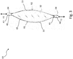
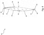
- the at least one mechanically deformable optical element 03 may be as in FIG Fig. 1 and Fig. 2 represented by at least one reflector 31 and / or as in Fig. 3 and Fig. 4 represented by at least one reversibly stretchable and / or compressible lens 32 act.
- the at least one mechanically deformable optical element 03 is at least one optical disc and / or holographic plate or a holographic film or optical disc arranged in the beam path between at least one light source 02 of the illuminant 01 and a lens of a vehicle light housing the illuminant 01 a holographic foil or the like.
- Holography can be used in particular for the guidance of light or generally electromagnetic radiation and can therefore be used in particular also in vehicle lights used.
- the mechanical deformation of the optical element 03 may provide, for example, that the optical element 03 as on in Fig. 1 and Fig. 2 represented example of a designed as a flexible reflector 31 mechanically deformable optical element 03 is reversibly bent by the action of the control element 04.
- the flexurally rigid, reversibly flexible reflector 31 undergoes a bending stress when it is deflected by the action of the control element 04 from a ground state forming, for example in Fig. 1 shown basic position in a bending state forming, for example in Fig. 2 shown mechanically bent bending position is deformed.
- the mechanical deformation may provide that the optical element 03 as at Fig. 3 and Fig. 4 illustrated example of a designed as a reversible stretchable and compressible lens 32 mechanically deformable optical element 03 by the action of a side of the lens 32 arranged adjusting element 04 or as in Fig. 3 and Fig. 4 shown by, for example, at two or more evenly distributed over the circumference of the lens 32 circumferentially arranged oppositely disposed adjusting elements 04 stretched and / or compressed.
- the reversibly stretchable and compressible lens 32 in this case experiences a tensile and / or a compressive load, which it encounters by slimming or thickening.
- a mechanically undeformed ground state as in Fig. 3 provided thicker shape of the lens 32 provide, whereas a mechanically deformed strain state as in Fig. 4 shown, slimmer shape of the lens 32 may provide, which the lens 32 under tensile stress by or the adjusting elements 04 occupies.
- the lens 32 assumes an undeformed ground state in an intermediate position.
- the lens 32 takes a in Fig. 3 illustrated compression state under a pressure generated by the one or more adjusting elements 04 and a pressure in Fig. 4 shown strain state under a generated by the or the adjusting elements 04 tensile stress.
- Fig. 3 and Fig. 4 each show a sectional view of an embodiment with a correspondingly reversibly stretchable and compressible lens 32, which by means of the edge of the lens 32 at two or more evenly distributed over its circumference arranged peripheral positions oppositely mounted adjusting elements 04 in shape, in particular in its thickness and thus the Curvature of their opposite, optically effective surfaces 33 can be changed.
- various curvatures may be provided on the opposite, optically effective surfaces 33 of the lens, as in FIG Fig. 3 and Fig. 4 indicated by different radii arrows R1, R2, R3, R4.
- the opposing, optically effective surfaces 33 of the lens 32 in the example in Fig. 3 illustrated ground state and / or im in Fig. 4 shown expansion state in each case the same curvatures corresponding to identical, by the arrows R1 and R2 in Fig. 3 shown radii or correspondingly identical, by the arrows R3 and R4 in Fig. 4 have shown radii.
- lens materials for such a reversibly stretchable and compressible lens 32 for example silicones can be used.
- At least one light source 02 of the light source 01 come due to the input described advantages preferably one or more LEDs 20 are used.
- At least one mechanically deformable optical element 03 of the illuminant 01 may additionally comprise an OLED 05 or be covered by an OLED 05.
- the OLED 05 in turn can contribute to the fulfillment of the same light function as the light source 02, or fulfill another light function or contribute accordingly.
- a specular surface of a flexible OLED 05 fabricated using a flexible substrate and flexible encapsulant may form a flexible reflector 32 as a mechanically deformable optical element 03, as exemplified in FIG Fig. 1 and Fig. 2 is shown.
- the metallic, reflective surfaces of OLEDs 05 with flexible substrate and flexible encapsulation can be used as reversibly flexible reflectors 31.
- the illuminant 01 consists of a flexible reflector 31 formed by a flexible OLED 05 as a mechanically deformable optical element 03, which is illuminated by a different light source 02 than the OLED 05, for example an LED 20, in the sense that the other light source 02 their light radiates into the flexible reflector 31 formed by the flexible OLED 05, which forms a variable, predetermined light distribution for this light, depending on the instantaneous deformation by at least one control element 04.
- the flexible OLED 05 used as a flexible reflector 31 can emit even light which can either contribute to a different light function or the same light function as that produced by the other light source 02, for example for the purpose of generating a dynamic light function or for highlighting in the frame an adaptive light function.
- segmented OLEDs 05 with segments which can be controlled individually for light emission, which can compensate for luminance differences on the reflector 31, for example, whereby the emission of the reflector 31 can be homogenized.
- a reflector-like arranged and provided as a flexible reflector 31 as a mechanically deformable optical element 03, flexible OLED 05 may advantageously be provided with a diffuser element, such as a scattering film and / or with a variety of micro-optics, for example on the outermost layer of an OLED 05.
- a diffuser element such as a scattering film and / or with a variety of micro-optics, for example on the outermost layer of an OLED 05.
- a transparent, flexible OLED 05 which is embodied as a reversibly deformable lens 32, may be integrated, for example, by forming its encapsulation, which is made, for example, of plastic and / or other materials, together with a first optically active surface 33 of the lens 32 forming flexible substrate of the OLED 05 a lens shape, for example, as in Fig. 3 and in Fig. 4 shown on one of the OLED 05 opposite, second optically active surface 33 of the lens 32 form.
- the color location of the light source 02 can thereby be corrected.
- the color location of the light source 02 which is preferably formed by an LED 20, changes the optical element 03, for example as in FIG Fig. 3 and Fig. 4
- the embedded OLED 05 can influence the color location of the overall emission by color mixing.
- a temperature-controlled color shift of the LED 20 taking place by the action of the operating temperature and / or the ambient temperature can be compensated for by the radiated matched OLED dominant wavelength.
- legal color locations can be maintained under certain conditions, for example.
- segmented OLEDs which, for example, can compensate for luminance differences in the lens 32, as a result of which the radiation from the lens 32 can become homogeneous.
- an OLED 05 may also be provided, in particular in conjunction with lenses and / or reflectors.
- luminous excitable material can be used on a flexible surface, such as quantum dots (QD).
- QD quantum dots
- the at least one adjusting element 04 is preferably a stroke and / or adjusting device which is controlled according to the adjusting travel along an actuating element axis and which can be shortened and which retracts an assumed extent along, for example, an actuating element axis against Direction of the actuator axis acting, in Fig. 1 and in Fig. 3 by double arrows F1, F2 indicated pressure and preferably also tensile forces holds until the at least one control element 04 driven by its actuation or actuation of the drive driven driven occupies a new extension along the actuator axis.
- an adjusting element 04 may be an electromechanical lifting cylinder or an electromechanical lifting column also called a telescopic column or telescopic drive. These have an electrical drive acting directly on the travel.
- a drive for an actuating element 04 is for example a linear drive in question.
- a linear drive refers to a drive, which leads to a translational movement in a straight line or along another predetermined course.
- Simple embodiments of linear drives are, for example, hydraulic and / or pneumatic cylinders.
- linear drives examples include ball screws, roller screws, such as roller screws with roller return or planetary roller, rack and pinion, electromechanical linear actuators, such as linear motors with electrodynamic operating principle, linear actuators with piezoelectric, electrostatic, electromagnetic, magnetorestrictive or thermoelectric operating principle.
- the at least one adjusting element 04 can alternatively or additionally be designed as a pneumatic and / or hydraulic cylinder.
- a gaseous or liquid fluid such as air or hydraulic oil, also be pressurized by means of an electrically driven pump.
- an influence on the travel is produced only indirectly via the fluid, which flows in and / or out of the valve element controlled as a pneumatic and / or hydraulic cylinder and thereby influences its travel.
- the at least one adjusting element 04 can be embodied as a hydraulic and / or pneumatic cylinder which can be pressurized on one or both sides with pressure.
- the maximum travel of the adjusting element 04 can be increased by a series connection of several linear drives, as is realized for example in telescopic columns.
- the at least one actuating element 04 acting on at least one mechanically deformable optical element 03 for purposes of influencing the light distribution of the light interacting with the optical element 03 and emitted by the light source 02 of the illuminant 01 by means of mechanical deformation is preferably a linear actuator 40.
- a piezoactuator 41 comprises a head and a foot part and a piezoelectric element arranged between the top and bottom part of a plurality of piezoelectric layers stacked one above the other and each forming a linear drive with a small travel.
- the piezoelectric element is constructed by using a material having a suitable crystal structure for the piezoelectric layers so that upon application of an external voltage, a mechanical reaction of the piezoelectric element takes place, which depending on the crystal structure and the contact areas of the electrical voltage, a pressure or a train in a predeterminable Represents direction.
- the piezoelectric element consists of a large number of stacked piezoelectric layers, between each of which an internal electrode of alternating polarity is located. On two opposite side surfaces are external electrodes via which the internal electrodes are supplied with electrical charge. Each inner electrode is connected to the respectively associated outer electrode. In order to avoid a short circuit between the outer electrodes, the inner electrodes must not occupy or cover the entire cross-sectional area of the piezoelectric element, but must maintain a certain distance from the outer electrode of the opposite polarity. In this case, the shape of the surface to be omitted depends on which regions of the circumference of the piezoelectric element are covered by the external electrodes.
- the piezoelectric actuator 41 may be at least partially surrounded by a holding body. Head and foot are on the one hand connected to the mechanically deformable optical element 03 and on the other hand with a formed for example by a conductor carrier 06 base support of the lamp 01 or, for example, a luminaire housing a lamp housing the light source connected, for example articulated, so that by applying a voltage to the piezoelectric actuator 41st For example, the mechanically deformable optical element 03 is compressed, stretched and / or bent.
- a mechanically deformable optical element 03 may alternatively be realized by a plurality of inherently rigid, relatively pivotally arranged Optikissepartien, for example, mirror parts or lens parts whose pivotal positions or their absolute and relative positions are each variable by at least one control element 04.
- the luminous means may comprise a conductor carrier 06.
- a conductor carrier 06 comes as a conductor carrier 06 a short as a printed circuit board, board or printed circuit board (PCB) referred to printed circuit board used.
- Embodiments in which the mechanically deformable optical element 03 can be fixed on one side to a conductor carrier 06 forming, for example, a base carrier of the illuminant 01 can alternatively be embodied as injection-molded circuit carriers produced in MID technology (MID technology: Molded interconnect device technology) ,
- the luminous means 01 provides for the generation of a dynamic and / or adaptive and / or active light effect by means of an optical deformation of an optical element 03 arranged in the beam path of the light emitted by a light source 02 of a luminous means 01, by actuation of an actuating element 04 which mechanical deformation is a change of the by the optical element 03 by its interaction with that of the light source 02 emitted light distribution light distribution 10, 11 entails.
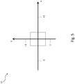
- Fig. 5 shows, for example, a light distribution 10 of a mechanically deformable optical element 03 in a basic position in a mechanically undeformed ground state
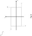
- Fig. 6 shows by way of example a light distribution 11 of a mechanically deformable optical element 03 in a deformation position in a mechanically deformed deformation state.
- X denotes the horizontal propagation of the light distribution while looking against the light propagation of the light previously interacting with the optical element 03
- Y denotes the vertical propagation of the light distribution
- the in Fig. 5 dimensionless illustrated light distribution 10 in the ground state has a much narrower spread ⁇ 1 in both the horizontal and in the vertical direction than the in Fig. 6 illustrated light distribution 11 in the deformation state, which in each axial direction in each case reaches the dimensionless value 1.
- an active light function can be realized by switching back and forth between the ground and deformation states depending on the presence of objects to be illuminated and / or shaded in the further course of the road.
- the light source 01 may, in conjunction with a vehicle lamp with a substantially of a lamp housing and a lens at least partially enclosed luminaire interior be realized.
- the light source 01 is in this case at least partially housed in the interior of the lamp.
- the light source serves to fulfill or contribute to a dynamic and / or an adaptive and / or an active light function of the vehicle light.
- the vehicle lamp may include additional bulbs, as implemented at the outset, which are provided for realizing light functions other than those at least partially fulfilled by the light source 01 with mechanically deformable optical element 03 and for this purpose can be accommodated, for example, in separate chambers formed in the interior of the lamp.
- the invention is an adaptive mirror and / or lens system in order, for example, to realize a multifunctional lighting chamber and / or to compensate for tolerances. Such compensation of tolerances can also be made on a fully assembled assembly, such as a taillight.
- the optical system can be readjusted or calibrated, for example, by comparison with an angle-dependent light intensity and / or luminance measurement.
- flexible or OLEDs 05 can additionally or alternatively be used in one or more directions, if appropriate also with a transparent property.
- such an OLED 05 may also emit light in multiple colors. This property can be realized by a so-called multiple stack, wherein several active, stimulable to light radiation layers are provided in the OLED structure, of which emit at least two light of different colors. With such a structured OLED 05 several light functions of a vehicle lamp can be operated.
- color location tolerances can also be at least partially corrected by, for example, adjusting the color mixture of the light source 02 interacting with the optical element 03, preferably embodied as LED 20, on a reflector-like OLED 05.
- the color location of a multicolor radiating OLED for example controlled by a corresponding sensor in a control circuit, could be readjusted depending on the temperature.
- advantages result from the fact that, depending on the deformation of the optical element or elements 03, light functions can be better illuminated in the sense that they fulfill, for example, a desired light distribution or multiple desired light distributions.
- the invention thus makes it possible, in addition to a complete solution of the task, to realize an adaptive and active optics for light systems used in vehicle lights.
- Adaptive and active optics are techniques that improve the quality of optical systems and at least reduce or compensate errors as much as possible. As a rule, this is done by movement or deformation of mirrors. Such measures are known above all from astronomy in the field of mirror telescopes.
- the illuminant 01 may alternatively or additionally comprise individual or a combination of several in the context of the prior art and / or in one or more of the documents mentioned in the prior art and / or features mentioned in the preceding description.
- the invention is particularly industrially applicable in the field of manufacturing vehicle lights, in particular motor vehicle lights.
Landscapes
- Engineering & Computer Science (AREA)
- General Engineering & Computer Science (AREA)
- Physics & Mathematics (AREA)
- Microelectronics & Electronic Packaging (AREA)
- Optics & Photonics (AREA)
- Non-Portable Lighting Devices Or Systems Thereof (AREA)
Priority Applications (1)
| Application Number | Priority Date | Filing Date | Title |
|---|---|---|---|
| EP17165713.3A EP3388731A1 (fr) | 2017-04-10 | 2017-04-10 | Module d'éclairage et véhicule automobile equipé avec un tel module |
Applications Claiming Priority (1)
| Application Number | Priority Date | Filing Date | Title |
|---|---|---|---|
| EP17165713.3A EP3388731A1 (fr) | 2017-04-10 | 2017-04-10 | Module d'éclairage et véhicule automobile equipé avec un tel module |
Publications (1)
| Publication Number | Publication Date |
|---|---|
| EP3388731A1 true EP3388731A1 (fr) | 2018-10-17 |
Family
ID=58530441
Family Applications (1)
| Application Number | Title | Priority Date | Filing Date |
|---|---|---|---|
| EP17165713.3A Withdrawn EP3388731A1 (fr) | 2017-04-10 | 2017-04-10 | Module d'éclairage et véhicule automobile equipé avec un tel module |
Country Status (1)
| Country | Link |
|---|---|
| EP (1) | EP3388731A1 (fr) |
Cited By (1)
| Publication number | Priority date | Publication date | Assignee | Title |
|---|---|---|---|---|
| DE102018129972A1 (de) * | 2018-11-27 | 2020-05-28 | Sick Ag | Optoelektronischer Sensor und Verfahren zur Erfassung von Objekten |
Citations (6)
| Publication number | Priority date | Publication date | Assignee | Title |
|---|---|---|---|---|
| DE4436620A1 (de) * | 1994-10-13 | 1996-04-18 | Bosch Gmbh Robert | Scheinwerfer für Fahrzeuge |
| EP1312967A1 (fr) * | 2001-11-15 | 2003-05-21 | Du Pont-Toray Company, Ltd. | Dispositif à réflexion |
| WO2011107904A1 (fr) * | 2010-03-03 | 2011-09-09 | Koninklijke Philips Electronics N.V. | Dispositif d'éclairage doté d'une lampe et d'une diode électroluminescente organique |
| DE102012004759A1 (de) * | 2012-03-08 | 2013-09-12 | GM Global Technology Operations LLC (n.d. Ges. d. Staates Delaware) | Rückleuchtenanordnung für ein Kraftfahrzeug |
| KR20140079962A (ko) * | 2012-12-20 | 2014-06-30 | 에스엘 주식회사 | 반사면 조절 모듈, 그리고 이를 적용한 차량용 램프 |
| DE102015114275A1 (de) * | 2015-08-27 | 2017-03-02 | Osram Oled Gmbh | Beleuchtungseinrichtung, Verfahren zum Betreiben einer Beleuchtungseinrichtung und System zur Beleuchtung eines Fahrzeugs |
-
2017
- 2017-04-10 EP EP17165713.3A patent/EP3388731A1/fr not_active Withdrawn
Patent Citations (6)
| Publication number | Priority date | Publication date | Assignee | Title |
|---|---|---|---|---|
| DE4436620A1 (de) * | 1994-10-13 | 1996-04-18 | Bosch Gmbh Robert | Scheinwerfer für Fahrzeuge |
| EP1312967A1 (fr) * | 2001-11-15 | 2003-05-21 | Du Pont-Toray Company, Ltd. | Dispositif à réflexion |
| WO2011107904A1 (fr) * | 2010-03-03 | 2011-09-09 | Koninklijke Philips Electronics N.V. | Dispositif d'éclairage doté d'une lampe et d'une diode électroluminescente organique |
| DE102012004759A1 (de) * | 2012-03-08 | 2013-09-12 | GM Global Technology Operations LLC (n.d. Ges. d. Staates Delaware) | Rückleuchtenanordnung für ein Kraftfahrzeug |
| KR20140079962A (ko) * | 2012-12-20 | 2014-06-30 | 에스엘 주식회사 | 반사면 조절 모듈, 그리고 이를 적용한 차량용 램프 |
| DE102015114275A1 (de) * | 2015-08-27 | 2017-03-02 | Osram Oled Gmbh | Beleuchtungseinrichtung, Verfahren zum Betreiben einer Beleuchtungseinrichtung und System zur Beleuchtung eines Fahrzeugs |
Non-Patent Citations (1)
| Title |
|---|
| JAHR, 2016 |
Cited By (1)
| Publication number | Priority date | Publication date | Assignee | Title |
|---|---|---|---|---|
| DE102018129972A1 (de) * | 2018-11-27 | 2020-05-28 | Sick Ag | Optoelektronischer Sensor und Verfahren zur Erfassung von Objekten |
Similar Documents
| Publication | Publication Date | Title |
|---|---|---|
| EP3330597B1 (fr) | Optique primaire, optique secondaire, module, dispositif, phares de véhicule automobile et système de phares | |
| DE102013223717B4 (de) | Kraftfahrzeugbeleuchtungseinrichtung mit zwei oder mehr in die gleiche Richtung strahlenden und in Hauptlichtaustrittsrichtung aufeinanderfolgend angeordneten OLEDs | |
| EP2041483B1 (fr) | Système d'éclairage flexible | |
| DE202013105597U1 (de) | Leuchtmittel und hiermit ausgestattete Kraftfahrzeugleuchte | |
| DE102007021865A1 (de) | Beleuchtungseinrichtung für ein Fahrzeug | |
| EP3355664A1 (fr) | Ampoule ayant un élément fluorescent et filtre de couleur et ampoule en étant équipé | |
| DE202015100207U1 (de) | Leuchtmittel und hiermit ausgestattete Fahrzeugleuchte | |
| EP2407347A1 (fr) | Affiche dans le rétroviseur et son procédé de fabrication | |
| DE202013103655U1 (de) | Kraftfahrzeugleuchte | |
| DE102019125265A1 (de) | Optische Anordnung, Scheinwerfer, Fahrzeug und Verfahren | |
| DE202014101538U1 (de) | Kraftfahrzeugleuchte | |
| DE102018009248B4 (de) | Kraftfahrzeug-Heckleuchte mit einem Lichtleiter, auf dessen Rückseite eine Grafik angeordnet ist, die dasselbe grafische Muster aufweist wie in die Vorderseite des Lichtleiters eingebrachte Auskopplungsstrukturen | |
| EP2886936A1 (fr) | Agent lumineux et lampe de véhicule automobile équipée de celui-ci | |
| DE202018106219U1 (de) | Optikelementeanordnung, Leuchtmittel umfassend eine solche Optikelementeanordnung, sowie mit einem entsprechenden Leuchtmittel ausgestattete Fahrzeugleuchte | |
| DE102018125758A1 (de) | Optikelement mit wellenlängenselektiver Beschichtung und hiermit ausgestattete Fahrzeugleuchte | |
| DE102017114513A1 (de) | Fahrzeugleuchtenanordnung mit OLED-Hintergrundbeleuchtung | |
| DE102015116382A1 (de) | Kraftfahrzeugleuchte | |
| DE202013105487U1 (de) | Kraftfahrzeugleuchte | |
| EP3324103A1 (fr) | Phare de véhicule avec fonction d'éclairage à action en profondeur | |
| EP3388731A1 (fr) | Module d'éclairage et véhicule automobile equipé avec un tel module | |
| EP2955063A1 (fr) | Lampe de véhicule automobile | |
| DE102014200606A1 (de) | Beleuchtetes Fensterelement | |
| EP3343089B1 (fr) | Dispositif d'éclairage et phare de véhicule en étant équipé | |
| DE202017101252U1 (de) | Leuchtmittel und hiermit ausgestattete Fahrzeugleuchte | |
| EP2565527A1 (fr) | Lampe de signalisation pour véhicules automobiles |
Legal Events
| Date | Code | Title | Description |
|---|---|---|---|
| PUAI | Public reference made under article 153(3) epc to a published international application that has entered the european phase |
Free format text: ORIGINAL CODE: 0009012 |
|
| AK | Designated contracting states |
Kind code of ref document: A1 Designated state(s): AL AT BE BG CH CY CZ DE DK EE ES FI FR GB GR HR HU IE IS IT LI LT LU LV MC MK MT NL NO PL PT RO RS SE SI SK SM TR |
|
| AX | Request for extension of the european patent |
Extension state: BA ME |
|
| STAA | Information on the status of an ep patent application or granted ep patent |
Free format text: STATUS: THE APPLICATION IS DEEMED TO BE WITHDRAWN |
|
| 18D | Application deemed to be withdrawn |
Effective date: 20190418 |