EP3388902A1 - Système d'automatisation sécurisée - Google Patents
Système d'automatisation sécurisée Download PDFInfo
- Publication number
- EP3388902A1 EP3388902A1 EP17165756.2A EP17165756A EP3388902A1 EP 3388902 A1 EP3388902 A1 EP 3388902A1 EP 17165756 A EP17165756 A EP 17165756A EP 3388902 A1 EP3388902 A1 EP 3388902A1
- Authority
- EP
- European Patent Office
- Prior art keywords
- point
- automation
- coupling
- communication line
- communication
- Prior art date
- Legal status (The legal status is an assumption and is not a legal conclusion. Google has not performed a legal analysis and makes no representation as to the accuracy of the status listed.)
- Granted
Links
Images

Classifications
-
- G—PHYSICS
- G05—CONTROLLING; REGULATING
- G05B—CONTROL OR REGULATING SYSTEMS IN GENERAL; FUNCTIONAL ELEMENTS OF SUCH SYSTEMS; MONITORING OR TESTING ARRANGEMENTS FOR SUCH SYSTEMS OR ELEMENTS
- G05B9/00—Safety arrangements
- G05B9/02—Safety arrangements electric
-
- G—PHYSICS
- G05—CONTROLLING; REGULATING
- G05B—CONTROL OR REGULATING SYSTEMS IN GENERAL; FUNCTIONAL ELEMENTS OF SUCH SYSTEMS; MONITORING OR TESTING ARRANGEMENTS FOR SUCH SYSTEMS OR ELEMENTS
- G05B19/00—Program-control systems
- G05B19/02—Program-control systems electric
- G05B19/04—Program control other than numerical control, i.e. in sequence controllers or logic controllers
- G05B19/048—Monitoring; Safety
-
- H—ELECTRICITY
- H04—ELECTRIC COMMUNICATION TECHNIQUE
- H04L—TRANSMISSION OF DIGITAL INFORMATION, e.g. TELEGRAPHIC COMMUNICATION
- H04L12/00—Data switching networks
- H04L12/28—Data switching networks characterised by path configuration, e.g. LAN [Local Area Networks] or WAN [Wide Area Networks]
- H04L12/40—Bus networks
-
- G—PHYSICS
- G05—CONTROLLING; REGULATING
- G05B—CONTROL OR REGULATING SYSTEMS IN GENERAL; FUNCTIONAL ELEMENTS OF SUCH SYSTEMS; MONITORING OR TESTING ARRANGEMENTS FOR SUCH SYSTEMS OR ELEMENTS
- G05B2219/00—Program-control systems
- G05B2219/20—Pc systems
- G05B2219/24—Pc safety
- G05B2219/24024—Safety, surveillance
-
- G—PHYSICS
- G05—CONTROLLING; REGULATING
- G05B—CONTROL OR REGULATING SYSTEMS IN GENERAL; FUNCTIONAL ELEMENTS OF SUCH SYSTEMS; MONITORING OR TESTING ARRANGEMENTS FOR SUCH SYSTEMS OR ELEMENTS
- G05B2219/00—Program-control systems
- G05B2219/20—Pc systems
- G05B2219/25—Pc structure of the system
- G05B2219/25006—Interface connected to fieldbus
-
- H—ELECTRICITY
- H04—ELECTRIC COMMUNICATION TECHNIQUE
- H04L—TRANSMISSION OF DIGITAL INFORMATION, e.g. TELEGRAPHIC COMMUNICATION
- H04L12/00—Data switching networks
- H04L12/28—Data switching networks characterised by path configuration, e.g. LAN [Local Area Networks] or WAN [Wide Area Networks]
- H04L12/40—Bus networks
- H04L2012/40208—Bus networks characterized by the use of a particular bus standard
- H04L2012/40221—Profibus
Definitions
- the invention relates to an automation system comprising a field bus with at least three coupling points, which are designed such that an automatic coupling and uncoupling of automation devices to the fieldbus is possible, wherein the respectively coupled automation devices are configured to establish mutually functionally secure connections via the fieldbus, whereby the functional safety achieved thereby serves to avoid dangerous malfunctions due to faults.
- functional safety means security for a part of an automation system which depends on the correct functioning of the safety-related systems and external risk-minimization means. Functional safety is given when every risk is safeguarded via safety functions so that the machine or the associated automation system can be described as safe. In this case, one speaks of safety-related automation systems.
- Functional safety is required, for example, with a tool changer.
- a tool changer For example, in a manufacturing cell several robots work alternately with several tools (eg welding guns).
- a robot grips a tool a functionally secure connection is established between the tool and the controller that controls the robot. Rarely used tools are shared by the robots and can therefore be used alternately on different robots.
- a secure communication connection to the tool may only be established to control the robot that is currently using the tool. Physical separation is out of the question as the controllers of the robots must communicate with each other.
- the coupling points can, for example, represent the flanges of the robots.
- the DE 10 2013 003 166 A1 discloses a security module for a field bus subscriber and an automation system. To establish a safety-related identification address is provided to arrange a setting in a housing of a security module. In this setting, for example, a DIL switch, a unique identification address is set.
- the object is achieved in that in addition to the fieldbus between at least a first docking point and a second docking point a point-to-point communication line is present, whereby for a to the first docking location and decoupled first automation device and for a second automation device which can be coupled to and decoupled from the second connection point has a pair relationship between the automation devices which can be coupled to and disconnected from the fieldbus, the connectable and disconnectable automation devices each having a point-to-point communication endpoint, which are configured next to Fieldbus communication in addition to establish a point-to-point communication via the point-to-point communication line and further comprises at least one of the connectable and disconnectable automation devices on a test means, which is designed to, based on by the additional point-to-point communication line possible additional communication to securely check whether the desired functionally secure connection between the automation devices has been established and whether also the desired automation device is at the opposite end of the point-to-point communication line, and does not erroneously establish a functionally
- an additional communication line between the automation devices is arranged according to the invention in addition to the fieldbus or next to a fieldbus communication line, with an additional connector for the automated coupling of the removable device is present at the coupling point.
- an additional communication line could be added to the fieldbus communication line and to the same connector, allowing functionally only "point-to-point" communication.
- the use of a point-to-point connection ensures that there is no error scenario for this communication protocol in which a telegram sent by the sender can be received by a receiver other than the desired one.
- Such a point-to-point coupling can be constructed such that the first automation device may safely communicate with the second automation device via the plug connection given at a point in time X.
- the given at the time X plug connection for the point-to-point communication therefore specifies which communication technology possible connection may come about. This allows the two programmable controllers to check whether they are really connected or not. Once this check has been made, a safe fieldbus connection between the programmable controllers can be used via the fieldbus.
- four coupling points are present, and in addition to the fieldbus between a third coupling point and a fourth coupling point, a second point-to-point communication line is present, whereby for a to the third coupling point and decoupled automation device and for a to the fourth Ankopplungsstelle on and decoupled automation device, a further pair relationship between on the field bus can be coupled and disconnected automation devices is present.
- the test means additionally comprise means for carrying out a challenge-response method.
- a secure check of the existing communication connection between two connectable and disconnectable automation devices can then be carried out with a challenge-response method.
- the first automation device then formulated with the means for performing the challenge-response method at any time a different request (Challenge), which must be answered by the second automation device or the partner automation device from the pair relationship in an appropriate manner (Response) as soon as the plug connection is made.
- the first automation device changes the request. In this way it is ensured that the request is not erroneously identified by a storage network component, e.g. Router, using an outdated message can be answered.
- the first point-to-point communication line and the second point-to-point communication line and the corresponding point-to-point communication end points arranged in the automation device are as a standardized IO-Link point-to-point coupling designed.
- a second embodiment variant proposes that the first point-to-point communication line and the second point-to-point communication line and the corresponding point-to-point communication end points arranged in the programmable controllers be used as a functionally secure IO-Link point-to-point connection. Design point coupling with a functionally secure protocol.
- the point-to-point communication end points are additionally configured as functionally secure point-to-point communication end points.
- the automation devices are assigned to a handling and or processing system, and the at least one automation device is designed as a replaceable tool with a field bus subscriber who for a control of actuators is formed on the tool.
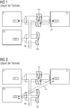
- FIG. 1 is the fundamental problem with the construction of functionally secure connections between connectable and disconnectable automation devices shown.
- the communication between a first automation device G1 and a second automation device G2 or between a third automation device G3 and the second automation device G2 is functionally safety-relevant.
- secure on the second programmable controller G2 Sensors and / or actuators are located, which should communicate via a secure channel with the first programmable controller G1 and the third programmable controller G3.
- the secure communication should also serve to reliably identify which devices are currently connected to each other.
- the second automation device G2 is allowed to perform certain actions as long as it is connected to the first automation device G1. For safety reasons, however, the same actions should be prohibited if the second automation device G2 is connected to the third automation device G3.
- the safety of automation devices for example, the following problem arises: An error in the use of the second programmable controller G2 by the programmable controllers G1, G3 must be recognized for reasons of functional safety with a high probability and lead to a safe state. For example, an error could occur in which the second automation device G2, which is connected to the first automation device G1, but it is due to a fault, a logical connection between the third automation device G3 and the second automation device G2 builds (see FIG. 2 ). An incorrect connection 20 has been erroneously established between the third automation device G3 and the second automation device G2.
- One hitherto common mechanism for detecting incorrectly constructed connections or for detecting addressing errors is the use of unique identifiers for the individual connections in the secure communication layer (eg "code name" in the case of Profisafe).
- the identifier "code name” does not provide the required error detection, which is desired for the case shown in a functionally secure communication layer fieldbus (as shown in the functionally safe communication layers shown in IEC 61874-3X).
- This is due to the fact that the identifier "code name” in the second automation device G2 can be visible from both other automation devices G1, G3, even if the automation devices are not coupled to the associated coupling points.
- an inventive automation system 1 is shown with a field bus FB.
- the first automation device G1 is a first coupling point S1 and the second automation device G2 is associated with a second coupling point S2.
- the second automation device G2 is docked in such a way that it has both a communication connection to the fieldbus FB and a communication link to an additional to the fieldbus FB between the first automation device G1 and the first coupling point S1 and the second coupling point S2 first point-to-point communication line 11 can establish a connection.
- a point-to-point communication line 11 is present in addition to the fieldbus FB between the first coupling point S1 and the second coupling point S2, as a result of which a first automation device G1 which can be coupled to and disconnected from the first coupling point S1 and to the second coupling point S2 on and decoupled second automation device G2 a pair relationship between on the field bus FB can be coupled and disconnected automation devices G1, G2 is present.
- the third coupling point S3 has a second point-to-point communication line 12 in addition to the fieldbus FB.
- This second point-to-point communication line 12 leads from the third coupling point S3 with a connector to the fourth coupling point S4.
- the second automation device G2 is coupled to the second coupling point S2, so may be located in the second automation device G2 second Connect point-to-point communication end point P2 via the additional point-to-point communication line 11 with a first point-to-point communication end point P1 arranged in the first automation device G1.
- a first test device PM1 which is designed to securely check on the basis of the additional communication via the first point-to-point communication line 11, whether the second automation device G2 is connected to the second coupling device S2 assigned to the first automation device G1.
- the third automation device G3 has a second test means PM2, which is configured to check securely whether the second automation device G2 is connected to the fourth coupling point S4.
- the second point-to-point communication line 12 is used.
- the test means PM1, PM2 further comprise means for carrying out a challenge-response method.
- An example of the challenge-response method is to use a sufficiently unique numerical value in the first automation device G1 and in the third automation device G3 (eg to generate N-bit random value).
- a random number generator RND is available.
- the generated random number is communicated to the second automation device G2 via the additionally introduced first point-to-point communication line 11.
- the second automation device G2 modifies the random value in a predetermined manner (eg bit-wise inversion or multiplication with an odd N-bit constant) and sends the result back.
- first automation device G1 or the third automation device G3 receives the expected return value, it can be concluded that a mechanical connection to the second automation device G2 has been established.
- Safety-related data can then be exchanged via the functionally reliable connection of the first automation device G1 to the second automation device G2 via the fieldbus FB.
- first functionally reliable fieldbus communication endpoint F1 and a second functionally reliable fieldbus communication endpoint F2 are available.
- the second automation device G2 has with the second functionally safe fieldbus communication endpoint F2 the corresponding counterpart for a functionally secure communication via the fieldbus FB.
- a functionally secure point-to-point communication is used.
- Functionally secure point-to-point communication can be achieved, for example, by a functionally secure IO-Link point-to-point link with a functionally secure protocol.
- the first automation device G1 has a first functionally secure point-to-point communication endpoint FP1 and the second automation device G1 has a second functionally secure point-to-point communication endpoint FP2.
- the third automation device G3 accordingly has a third functionally secure point-to-point communication endpoint FP3.
- the additional functionally secure point-to-point communication end points FP1 and FP2 are used for communication via the first point-to-point communication line 11.
Landscapes
- Engineering & Computer Science (AREA)
- Physics & Mathematics (AREA)
- General Physics & Mathematics (AREA)
- Automation & Control Theory (AREA)
- Computer Networks & Wireless Communication (AREA)
- Signal Processing (AREA)
- Small-Scale Networks (AREA)
Priority Applications (3)
| Application Number | Priority Date | Filing Date | Title |
|---|---|---|---|
| EP17165756.2A EP3388902B1 (fr) | 2017-04-10 | 2017-04-10 | Système d'automatisation sécurisée |
| CN201810238484.1A CN108693813B (zh) | 2017-04-10 | 2018-03-21 | 安全导向的自动化系统 |
| US15/948,454 US10599117B2 (en) | 2017-04-10 | 2018-04-09 | Safety-oriented automation system |
Applications Claiming Priority (1)
| Application Number | Priority Date | Filing Date | Title |
|---|---|---|---|
| EP17165756.2A EP3388902B1 (fr) | 2017-04-10 | 2017-04-10 | Système d'automatisation sécurisée |
Publications (3)
| Publication Number | Publication Date |
|---|---|
| EP3388902A1 true EP3388902A1 (fr) | 2018-10-17 |
| EP3388902C0 EP3388902C0 (fr) | 2026-02-18 |
| EP3388902B1 EP3388902B1 (fr) | 2026-02-18 |
Family
ID=58664453
Family Applications (1)
| Application Number | Title | Priority Date | Filing Date |
|---|---|---|---|
| EP17165756.2A Active EP3388902B1 (fr) | 2017-04-10 | 2017-04-10 | Système d'automatisation sécurisée |
Country Status (3)
| Country | Link |
|---|---|
| US (1) | US10599117B2 (fr) |
| EP (1) | EP3388902B1 (fr) |
| CN (1) | CN108693813B (fr) |
Cited By (1)
| Publication number | Priority date | Publication date | Assignee | Title |
|---|---|---|---|---|
| EP4502739A1 (fr) * | 2023-07-31 | 2025-02-05 | Siemens Aktiengesellschaft | Procédé de contrôle d'une fonctionnalité d'un circuit de commande d'une machine au moyen du circuit, produit programme informatique, support de stockage lisible par ordinateur et circuit |
Families Citing this family (1)
| Publication number | Priority date | Publication date | Assignee | Title |
|---|---|---|---|---|
| EP3716568A1 (fr) * | 2019-03-28 | 2020-09-30 | Siemens Aktiengesellschaft | Identification de connexion sécuritaire fonctionnelle pour une connexion m2m |
Citations (5)
| Publication number | Priority date | Publication date | Assignee | Title |
|---|---|---|---|---|
| US20040158713A1 (en) * | 2003-01-28 | 2004-08-12 | Tom Aneweer | Process control system with an embedded safety system |
| EP1933497A1 (fr) * | 2006-12-12 | 2008-06-18 | Abb Research Ltd. | Procédé et serveur pour autoriser des commandes critiques |
| US20090105849A1 (en) * | 1997-08-21 | 2009-04-23 | Fieldbus Foundation | System and method for implementing safety instrumented systems in a fieldbus architecture |
| DE102013003166A1 (de) | 2013-02-26 | 2014-08-28 | Festo Ag & Co. Kg | Sicherheitsmodul für einen Feldbusteilnehmer und Automatisierungssystem |
| US20150229654A1 (en) * | 2014-02-10 | 2015-08-13 | Stmicroelectronics International N.V. | Secured transactions in internet of things embedded systems networks |
Family Cites Families (7)
| Publication number | Priority date | Publication date | Assignee | Title |
|---|---|---|---|---|
| US6014612A (en) * | 1997-10-02 | 2000-01-11 | Fisher Controls International, Inc. | Remote diagnostics in a process control network having distributed control functions |
| US7027893B2 (en) * | 2003-08-25 | 2006-04-11 | Ati Industrial Automation, Inc. | Robotic tool coupler rapid-connect bus |
| DE102008050102B4 (de) * | 2008-10-06 | 2010-11-04 | Phoenix Contact Gmbh & Co. Kg | Kommunikationsentität zur Kommunikation über ein busorientiertes Kommunikationsnetzwerk |
| US8948782B2 (en) * | 2012-12-21 | 2015-02-03 | Qualcomm Incorporated | Proximity determination based on distance ratios |
| US9903940B2 (en) * | 2013-12-30 | 2018-02-27 | Qualcomm Incorporated | Entrusted device localization scheme using ultrasound signatures |
| GB2535839B (en) * | 2015-01-08 | 2021-06-09 | Fisher Rosemount Systems Inc | Apparatus and methods to communicatively couple field devices to controllers in a process control system |
| CN204870600U (zh) * | 2015-04-20 | 2015-12-16 | 南京金龙新能源汽车研究院有限公司 | 一种电动汽车智能整车控制器 |
-
2017
- 2017-04-10 EP EP17165756.2A patent/EP3388902B1/fr active Active
-
2018
- 2018-03-21 CN CN201810238484.1A patent/CN108693813B/zh active Active
- 2018-04-09 US US15/948,454 patent/US10599117B2/en active Active
Patent Citations (5)
| Publication number | Priority date | Publication date | Assignee | Title |
|---|---|---|---|---|
| US20090105849A1 (en) * | 1997-08-21 | 2009-04-23 | Fieldbus Foundation | System and method for implementing safety instrumented systems in a fieldbus architecture |
| US20040158713A1 (en) * | 2003-01-28 | 2004-08-12 | Tom Aneweer | Process control system with an embedded safety system |
| EP1933497A1 (fr) * | 2006-12-12 | 2008-06-18 | Abb Research Ltd. | Procédé et serveur pour autoriser des commandes critiques |
| DE102013003166A1 (de) | 2013-02-26 | 2014-08-28 | Festo Ag & Co. Kg | Sicherheitsmodul für einen Feldbusteilnehmer und Automatisierungssystem |
| US20150229654A1 (en) * | 2014-02-10 | 2015-08-13 | Stmicroelectronics International N.V. | Secured transactions in internet of things embedded systems networks |
Cited By (1)
| Publication number | Priority date | Publication date | Assignee | Title |
|---|---|---|---|---|
| EP4502739A1 (fr) * | 2023-07-31 | 2025-02-05 | Siemens Aktiengesellschaft | Procédé de contrôle d'une fonctionnalité d'un circuit de commande d'une machine au moyen du circuit, produit programme informatique, support de stockage lisible par ordinateur et circuit |
Also Published As
| Publication number | Publication date |
|---|---|
| US10599117B2 (en) | 2020-03-24 |
| EP3388902C0 (fr) | 2026-02-18 |
| CN108693813A (zh) | 2018-10-23 |
| EP3388902B1 (fr) | 2026-02-18 |
| CN108693813B (zh) | 2023-11-07 |
| US20180292796A1 (en) | 2018-10-11 |
Similar Documents
| Publication | Publication Date | Title |
|---|---|---|
| EP1923759B1 (fr) | Procédé et système de transmission de données sécurisée | |
| EP4235323B1 (fr) | Procédé et appareil de validation automatique de fonctions de sécurité sur un système de sécurité modulaire | |
| DE102007050708B4 (de) | System zum Betreiben wenigstens eines nicht-sicherheitskritischen und wenigstens eines sicherheitskritischen Prozesses | |
| DE102014110017A1 (de) | Steuer- und Datenübertragungssystem, Gateway-Modul, E/A-Modul und Verfahren zur Prozesssteuerung | |
| DE102011107318A1 (de) | Verfahren zur Konfigurierung eines Kommunikationsschnittstellenmoduls in einem Steuerungs- oder Automatisierungssystem | |
| EP2981868A1 (fr) | Système de commande et de transmission de données, dispositif de traitement et procédé de commande de processus redondante à redondance décentralisée | |
| EP1068561B1 (fr) | Procede et dispositif de transmission de donnees proteges contre les defaillances | |
| DE102008044018A1 (de) | Verfahren zum Bestimmen einer Sicherheitsstufe und Sicherheitsmanager | |
| DE102014111361A1 (de) | Verfahren zum Betreiben einer Sicherheitssteuerung und Automatisierungsnetzwerk mit einer solchen Sicherheitssteuerung | |
| EP3745217B1 (fr) | Dispositif de surveillance d' un système de traitement et de transmission de données. | |
| DE102015122066A1 (de) | Fehlersicheres Modul zum Anschluss an einen Feldbuskoppler, Feldbuskoppler, System und Verfahren zum Konfigurieren eines derartigen fehlersicheren Moduls | |
| EP2375636A1 (fr) | Dispositif et procédé de configuration d'un système de bus | |
| DE102016222938B4 (de) | Sicherheitsmodul für ein Automatisierungssystem, Verfahren zum Betreiben eines Sicherheitsmoduls in einem Automatisierungssystem sowie Automatisierungssystem | |
| EP3388902B1 (fr) | Système d'automatisation sécurisée | |
| EP3470939B1 (fr) | Procédé et système de surveillance de l'intégrité de sécurité d'une fonction de sécurité fournie par un système de sécurité | |
| EP3470937B1 (fr) | Procédé et dispositifs de surveillance du temps réactionnel d'une fonction de sécurité fournie par un système de sécurité | |
| EP1128241A2 (fr) | Procédé et dispositif de surveillance d' un dispositif de commande | |
| EP3484127A1 (fr) | Procédé et dispositif de distribution sécurisée d'adresses à des modules dans un réseau, dispositif d'adressage, produit-programme informatique et installation industrielle | |
| EP3599525B1 (fr) | Procédé de communication sécurisée de données sur une machine-outil à commande numérique | |
| EP3267271A1 (fr) | Systeme d'automatisation et procede de fonctionnement | |
| EP3388901B1 (fr) | Système d'automatisation sécurisée | |
| EP3869331A1 (fr) | Procédé d'ajustement des adresses f et module d'installations | |
| EP2741451A1 (fr) | Procédé de liaison d'un module matériel sur un bus de terrain | |
| EP1921525B1 (fr) | Méthode d'opération d'un système de sécurité | |
| EP2950174A1 (fr) | Méthode et appareil pour surveiller en toute sécurité l'état de deux dispositifs |
Legal Events
| Date | Code | Title | Description |
|---|---|---|---|
| PUAI | Public reference made under article 153(3) epc to a published international application that has entered the european phase |
Free format text: ORIGINAL CODE: 0009012 |
|
| STAA | Information on the status of an ep patent application or granted ep patent |
Free format text: STATUS: THE APPLICATION HAS BEEN PUBLISHED |
|
| AK | Designated contracting states |
Kind code of ref document: A1 Designated state(s): AL AT BE BG CH CY CZ DE DK EE ES FI FR GB GR HR HU IE IS IT LI LT LU LV MC MK MT NL NO PL PT RO RS SE SI SK SM TR |
|
| AX | Request for extension of the european patent |
Extension state: BA ME |
|
| STAA | Information on the status of an ep patent application or granted ep patent |
Free format text: STATUS: REQUEST FOR EXAMINATION WAS MADE |
|
| 17P | Request for examination filed |
Effective date: 20190404 |
|
| RBV | Designated contracting states (corrected) |
Designated state(s): AL AT BE BG CH CY CZ DE DK EE ES FI FR GB GR HR HU IE IS IT LI LT LU LV MC MK MT NL NO PL PT RO RS SE SI SK SM TR |
|
| STAA | Information on the status of an ep patent application or granted ep patent |
Free format text: STATUS: EXAMINATION IS IN PROGRESS |
|
| 17Q | First examination report despatched |
Effective date: 20210329 |
|
| REG | Reference to a national code |
Ref country code: DE Free format text: PREVIOUS MAIN CLASS: G05B0009020000 Ref country code: DE Ref legal event code: R079 Ref document number: 502017017220 Country of ref document: DE Free format text: PREVIOUS MAIN CLASS: G05B0009020000 Ipc: G05B0019048000 |
|
| GRAP | Despatch of communication of intention to grant a patent |
Free format text: ORIGINAL CODE: EPIDOSNIGR1 |
|
| STAA | Information on the status of an ep patent application or granted ep patent |
Free format text: STATUS: GRANT OF PATENT IS INTENDED |
|
| RIC1 | Information provided on ipc code assigned before grant |
Ipc: G05B 19/048 20060101AFI20250919BHEP Ipc: G05B 9/02 20060101ALI20250919BHEP |
|
| INTG | Intention to grant announced |
Effective date: 20251013 |
|
| GRAS | Grant fee paid |
Free format text: ORIGINAL CODE: EPIDOSNIGR3 |
|
| GRAA | (expected) grant |
Free format text: ORIGINAL CODE: 0009210 |
|
| STAA | Information on the status of an ep patent application or granted ep patent |
Free format text: STATUS: THE PATENT HAS BEEN GRANTED |
|
| AK | Designated contracting states |
Kind code of ref document: B1 Designated state(s): AL AT BE BG CH CY CZ DE DK EE ES FI FR GB GR HR HU IE IS IT LI LT LU LV MC MK MT NL NO PL PT RO RS SE SI SK SM TR |
|
| REG | Reference to a national code |
Ref country code: CH Ref legal event code: F10 Free format text: ST27 STATUS EVENT CODE: U-0-0-F10-F00 (AS PROVIDED BY THE NATIONAL OFFICE) Effective date: 20260218 Ref country code: GB Ref legal event code: FG4D Free format text: NOT ENGLISH |
|
| REG | Reference to a national code |
Ref country code: IE Ref legal event code: FG4D Free format text: LANGUAGE OF EP DOCUMENT: GERMAN |
|
| U01 | Request for unitary effect filed |
Effective date: 20260218 |
|
| U07 | Unitary effect registered |
Designated state(s): AT BE BG DE DK EE FI FR IT LT LU LV MT NL PT RO SE SI Effective date: 20260223 |