EP3869331A1 - Procédé d'ajustement des adresses f et module d'installations - Google Patents
Procédé d'ajustement des adresses f et module d'installations Download PDFInfo
- Publication number
- EP3869331A1 EP3869331A1 EP20158490.1A EP20158490A EP3869331A1 EP 3869331 A1 EP3869331 A1 EP 3869331A1 EP 20158490 A EP20158490 A EP 20158490A EP 3869331 A1 EP3869331 A1 EP 3869331A1
- Authority
- EP
- European Patent Office
- Prior art keywords
- sub
- automation device
- main
- source address
- automation
- Prior art date
- Legal status (The legal status is an assumption and is not a legal conclusion. Google has not performed a legal analysis and makes no representation as to the accuracy of the status listed.)
- Withdrawn
Links
Images


Classifications
-
- G—PHYSICS
- G06—COMPUTING OR CALCULATING; COUNTING
- G06F—ELECTRIC DIGITAL DATA PROCESSING
- G06F9/00—Arrangements for program control, e.g. control units
- G06F9/06—Arrangements for program control, e.g. control units using stored programs, i.e. using an internal store of processing equipment to receive or retain programs
- G06F9/44—Arrangements for executing specific programs
- G06F9/445—Program loading or initiating
- G06F9/44552—Conflict resolution, i.e. enabling coexistence of conflicting executables
-
- Y—GENERAL TAGGING OF NEW TECHNOLOGICAL DEVELOPMENTS; GENERAL TAGGING OF CROSS-SECTIONAL TECHNOLOGIES SPANNING OVER SEVERAL SECTIONS OF THE IPC; TECHNICAL SUBJECTS COVERED BY FORMER USPC CROSS-REFERENCE ART COLLECTIONS [XRACs] AND DIGESTS
- Y02—TECHNOLOGIES OR APPLICATIONS FOR MITIGATION OR ADAPTATION AGAINST CLIMATE CHANGE
- Y02P—CLIMATE CHANGE MITIGATION TECHNOLOGIES IN THE PRODUCTION OR PROCESSING OF GOODS
- Y02P90/00—Enabling technologies with a potential contribution to greenhouse gas [GHG] emissions mitigation
- Y02P90/02—Total factory control, e.g. smart factories, flexible manufacturing systems [FMS] or integrated manufacturing systems [IMS]
Definitions
- the invention relates to a method for adapting F-addresses for a second system module to be put into operation for an already existing first system module, the system modules each having a first main automation device or a second main automation device, a plurality of sub-automation devices and a network
- the main automation devices and the sub-automation devices are designed for functionally safe communication via the network and F-addresses have already been assigned in the first system module in advance for functionally safe connection identification and for functionally safe communication and, as a result, the first main automation device is given a first F-source address and an F-destination address was assigned to each of the sub-automation devices, with a first user program being loaded in the first main automation device, in which the F-destination addresses for Addressing can be used.
- a series machine is to be understood as a machine, e.g. a tool changer, preferably in a modular design. These machines can have the same components and the same addresses as well as the assignment of namespaces. In a plant operation, it can therefore happen that two series machines of the same type are used and are also linked via a network.
- an address relationship including a destination and a source address, for example for Profinet participants, must be unique across the network.
- PROFIsafe safety protocol With Profisafe, a 32-bit code name, which corresponds to an address relationship, is used for unique connection identification. The code names cannot be clearly assigned anywhere in the world.
- An F-address is a unique address relationship between two communication participants.
- the F address is used to uniquely identify a source and a target.
- Each F-I / O therefore has two address parts: F-source address, F-destination address.
- One or both parts of the address can be used for protection.
- the object is achieved in that, for adapting the F-addresses for the second system module, which according to a system concept for the series production of system modules starting from an original system module analogous to the first system module
- the following steps are carried out: A copy of the first user program is loaded into the second main automation device and a second user program is thus generated in the second main automation device, a second F-source address is assigned for the second main automation device, and a configuration telegram is sent from the second main automation device the second F-source address and the respective F-destination address are sent to the sub-automation devices of the second system module, the second F-source address being stored in the sub-automation devices, and the second network communicating during this process is separated from the first network, the intended adaptation of the F-source address is recognized in the sub-automation devices by means of a configuration telegram and a check is then carried out to determine whether the configuration telegram also contains the respective F-destination address
- a new F-source address i.e. a master ID
- the second, new F-source address or new master ID is provided in such a way that it is stored outside of the user program on the second main automation device. This has the advantage that the copied and previously checked user program is not changed.
- an F-source address or a master ID could be a real random value of at least 32 bits (e.g. 32-bit CRC of a Microsoft GUID that is assigned during the commissioning test and is not part of the safe automation program).
- the master ID could be a unique value that is assigned manually during commissioning and must differ from all master IDs in the system.
- F-destination address per connection, which is unique within a system module.
- a sub-automation device could also set up several connections and accordingly has several F-destination addresses.
- F source address master ID
- master ID which is unique within a system module and which can be different for each connection, but is preferably identical for all connections of a system module. In the case of communication traffic across system modules, another master ID could be used for the connection.
- the F-destination address and the F-source address are stored in both end points of a connection (i.e. in the main automation device and in the sub-automation device).
- a receiver or the sub-automation device checks the IDs or F-destination address and F-source address for each telegram. This enables addressing errors to be recognized if the IDs, namely the F-destination address and the F-source address, do not match the stored addresses.
- a type of communication protocol is used which writes the master ID in all devices assigned to the machine and, in addition, the communicative separation from the other machines in the network is carried out by suitable means during this process.
- a logic or another sequence program recognizes the change in the master ID in the secure sub-automation devices (devices) as permissible if the corresponding F-target address (sub-ID) in the request corresponds to the expectations in the sub-automation device. The expectation is that the request will have the same destination address as it is in the request telegram.
- each time there is communication to a sub-automation device in the sub-automation device it is advantageously checked whether the stored F-addresses match those in a telegram received for the communication.
- a first signature is formed via a code of the user program of the first main automation device and that this first signature is also supplied to the second main automation device when the second user program is generated, with the second
- the main automation device forms a second signature via the second user program and carries out a comparison of the two signatures and for in the event of inequality, an error message is issued.
- This functionally safe communication via the network is advantageously carried out using OPC UA Safety or PROFIsafe.
- the task mentioned at the beginning is for a system module comprising a main automation device, a plurality of sub-automation devices, a network, the main automation device and the sub-automation devices being designed for functionally safe communication via the network; for this purpose, the main automation device has a first F-source address and the sub-automation devices designed accordingly with an F target address, and a fail-safe user program is stored in the main automation device, achieved in that a master flow protocol is implemented in the main automation device for an adaptation of the F addresses for the main automation device and the sub-automation devices, the master flow protocol is designed to wait for a command which requests the adaptation of the F-addresses and to carry out the following: A second F-source address is either generated internally or with the command and then a configuration telegram with the second F-source address and the respective F-destination address is sent to the sub-automation devices To recognize the configuration telegram and then to check whether the configuration telegram also contains the respective F-destination address of the respective sub-automat
- the fail-safe user program once defined and programmed in the original system module, which has been checked, tested and, if necessary, TÜV certified, it is of particular advantage if a signature is created using this tested, checked, certified user program.
- the master process log in the main automation module is also designed to receive a first signature from an original user program and to form a second signature using the stored fail-safe user program and to compare the two signatures, with the master process log in the event of inequality sends an error message. If this error message appears, a user knows immediately that there is an error in his fail-safe user program, which was copied from another system module or another main automation device, and that he cannot start up the system. This is characterized by the different signatures of the user programs.
- a first system module S1 is shown as a series machine.
- the system module S1 comprises a main automation device PLC1, a plurality of sub-automation devices D1, D2, D3, which are all connected to a first network N1.
- the main automation device PLC1 and the first sub-automation device D1, the second sub-automation device D2 and the third sub-automation device D3 are all designed for functionally safe communication via the first network N1.
- the main automation device PLC1 is configured with a first F-source address FQ1 and the sub-automation devices D1, D2, D3 correspondingly with an F-destination address FZ1, FZ2, FZ3.
- a fail-safe user program P1 is stored in an executable manner in the main automation device PLC1. In an original user program P0, a signature was already formed once via the program code.
- This signature created by the original user program, means that the original user program has been tested, checked and certified once and therefore works without errors.
- This signature is given to the first user program in the first main automation device PLC1.
- the signature is marked with Sig.
- a master flow protocol 50 is implemented in the main automation device PLC1.
- the master run log 50 is designed to respond to a command (see also FIG 4 ), which asks to wait to adapt the F-addresses.
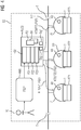
- a second system module S2 is switched ready for operation during a commissioning test of a series machine.
- a commissioning engineer 10 specifies a new master ID, that is to say the second (new) F-source address FQ2, for the second main automation device PLC2 via an operator panel HMI when the second system module S2 is commissioned. Accordingly, the second F-source address FQ2 is sent from the commissioning engineer 10 to the second main automation device PLC2.
- the master run log 50 is implemented in the second main automation device PLC2.
- the master flow protocol 50 ensures that a configuration telegram KT1, KT2, KT3 with the second (new) F-source address FQ2 and the respective F-destination address FZ1, FZ2, FZ3 is sent to the respective sub-automation device D1, D2, D3.
- a slave flow protocol 60 is implemented in the sub-automation devices D1, D2, D3. This is designed to recognize the intended adaptation of the F source address FQ2 by means of the configuration telegram KT1, KT2, KT3 in the automation devices D1, D2, D3 and then to check whether the configuration telegram KT1, KT2, KT3 also contains the respective F target address FZ1 , FZ2, FZ3 of the respective sub-automation device D1, D2, D3 for which the F-source address FQ2 is to be adapted. If this check turns out positive, the second (new) F-source address FQ2 is adopted for the sub-automation device D1, D2, D3. During this process, the second network N2 is via a separation T from other networks, in particular with regard to FIG 3 , separated from the first network N1.
- the series machine network SV comprising the first system module S1 and the second system module S2 is shown in context.
- the original system module S0 is located as a shadow behind the first system module S1, on the basis of which all other series machines are put into operation with the aid of the procedure for adapting F-addresses.
- an original user program P0 was also created, the code of which was used to create a signature Sig.
- This signature Sig is supplied when the copy of the first user program P1 is created in the second user program P2, and a signature Sig 'is also formed in the second main automation device PLC2 via the copied second user program P2.
- the first main automation device PLC1 now maintains a first functionally safe connection fsV1 1 , a second functionally safe connection fsV2 1 and a third functionally safe connection fsV3 1 to each of the sub-automation devices D1, D2, D3.
- a functionally safe connection can also be established between the first main automation device PLC1 and the second main automation device PLC2.
- the second main automation device PLC2 now maintains a first functionally safe connection fsV1 2 , a second functionally safe connection fsV2 2 and a third functionally safe connection fsV3 2 to its sub-automation devices D1, D2, D3.
- FIG 2 shows schematically a fail-safe first user program P1. It contains a first F-source address FQ1, which was specified, for example, and the corresponding F-destination addresses FZ1, ..., FZ3.
- a first communication function block KFB1 and finally a third communication function block KFB3 are used within the master run log 50 the communication telegrams KT1, KT2, KT3 for reparameterization of the submodules are formed.
- FIG 5 shows the master sequence log 50 as a program flow chart.
- a step "Wait for HMI command” 51 the change request for a master ID or the F source address is awaited.
- a further step "HMI command received” 52 the change is confirmed.
- the F-source address is stored in a storage step 53 and in the step "send configuration telegram" 54 it is sent to the sub-automation devices D1, D2, D3 until all sub-automation devices D1, D2, D3 are supplied with the new addresses, until the end is finally reached is.
- a waiting step 61 “wait for a command to change the master ID” and the following program step “command received” 62 start a test 63 as to whether the F target address is correct; if this is the case, the step “take over new F -Source address "64 the new F-source address is accepted, if this is not the case, an error message 65 is generated.
Landscapes
- Engineering & Computer Science (AREA)
- Software Systems (AREA)
- Theoretical Computer Science (AREA)
- Physics & Mathematics (AREA)
- General Engineering & Computer Science (AREA)
- General Physics & Mathematics (AREA)
- Programmable Controllers (AREA)
Priority Applications (1)
| Application Number | Priority Date | Filing Date | Title |
|---|---|---|---|
| EP20158490.1A EP3869331A1 (fr) | 2020-02-20 | 2020-02-20 | Procédé d'ajustement des adresses f et module d'installations |
Applications Claiming Priority (1)
| Application Number | Priority Date | Filing Date | Title |
|---|---|---|---|
| EP20158490.1A EP3869331A1 (fr) | 2020-02-20 | 2020-02-20 | Procédé d'ajustement des adresses f et module d'installations |
Publications (1)
| Publication Number | Publication Date |
|---|---|
| EP3869331A1 true EP3869331A1 (fr) | 2021-08-25 |
Family
ID=69723816
Family Applications (1)
| Application Number | Title | Priority Date | Filing Date |
|---|---|---|---|
| EP20158490.1A Withdrawn EP3869331A1 (fr) | 2020-02-20 | 2020-02-20 | Procédé d'ajustement des adresses f et module d'installations |
Country Status (1)
| Country | Link |
|---|---|
| EP (1) | EP3869331A1 (fr) |
Cited By (1)
| Publication number | Priority date | Publication date | Assignee | Title |
|---|---|---|---|---|
| WO2025039590A1 (fr) * | 2023-08-22 | 2025-02-27 | 宇通客车股份有限公司 | Système de commande de charge, procédé de commande associé et véhicule à énergie nouvelle utilisant un système de commande de charge |
Citations (1)
| Publication number | Priority date | Publication date | Assignee | Title |
|---|---|---|---|---|
| DE102016107045A1 (de) * | 2016-04-15 | 2017-10-19 | Endress + Hauser Gmbh + Co. Kg | Verfahren und System zum sicheren Konfigurieren eines Feldgeräts der Prozessautomatisierung |
-
2020
- 2020-02-20 EP EP20158490.1A patent/EP3869331A1/fr not_active Withdrawn
Patent Citations (1)
| Publication number | Priority date | Publication date | Assignee | Title |
|---|---|---|---|---|
| DE102016107045A1 (de) * | 2016-04-15 | 2017-10-19 | Endress + Hauser Gmbh + Co. Kg | Verfahren und System zum sicheren Konfigurieren eines Feldgeräts der Prozessautomatisierung |
Cited By (1)
| Publication number | Priority date | Publication date | Assignee | Title |
|---|---|---|---|---|
| WO2025039590A1 (fr) * | 2023-08-22 | 2025-02-27 | 宇通客车股份有限公司 | Système de commande de charge, procédé de commande associé et véhicule à énergie nouvelle utilisant un système de commande de charge |
Similar Documents
| Publication | Publication Date | Title |
|---|---|---|
| EP3098673B1 (fr) | Procede et dispositif de validation automatique de fonctions de securite sur un systeme de securite construit de façon modulaire | |
| EP2302841A1 (fr) | Procédé et dispositif de communication orientée vers la sécurité dans le réseau de communication d'une installation d'automatisation | |
| EP3177973B1 (fr) | Procédé de fonctionnement d'un automate de sécurité et réseau d'automatisation ayant un tel automate de sécurité | |
| DE102006013578B4 (de) | Verfahren und Steuer- und Datenübertragungsanlage zum Überprüfen des Einbauortes eines sicheren Kommunikationsteilnehmers | |
| DE102017109886A1 (de) | Steuerungssystem zum Steuern von sicherheitskritischen und nichtsicherheitskritischen Prozessen mit Master-Slave-Funktionalität | |
| WO2009036891A1 (fr) | Procédé de transmission sécurisée de données et appareil approprié | |
| EP3113461A1 (fr) | Procédé d'établissement de liaisons de communication à des appareils de commande à fonctionnement redondant d'un système d'automatisation industrielle et appareil de commande | |
| EP2226693A1 (fr) | Appareil de programmation destiné à la projection d'une liaison de communication entre des composants d'automatisation dans un agencement d'automatisation industriel | |
| EP2480940B1 (fr) | Procédé de mise à disposition de fonctions de sécurité | |
| EP3051779A1 (fr) | Procédé d'identification de liaison avec sécurité de fonctionnement et système de communication | |
| EP3869331A1 (fr) | Procédé d'ajustement des adresses f et module d'installations | |
| EP2811352A1 (fr) | Procédé de traitement d'un projet d'automatisation par une pluralité de stations de traitement | |
| EP2283426B1 (fr) | Procédé et dispositif permettant de corriger des informations transmises sous forme numérique | |
| DE102021127310B4 (de) | System und Verfahren zur Datenübertragung | |
| EP3599525B1 (fr) | Procédé de communication sécurisée de données sur une machine-outil à commande numérique | |
| LU102517B1 (de) | Verfahren zur Einbindung in eine Datenübertragung von einer Anzahl von an einer I/O-Station angeschlossenen I/O-Modulen, ein Stationskopf zur Ausführung eines solchen Verfahrens und ein System mit einem solchen Stationskopf | |
| EP3388902A1 (fr) | Système d'automatisation sécurisée | |
| DE102022104113A1 (de) | Verfahren zum Bereitstellen eines Datenzugriffs auf eine technische Einrichtung und technische Einrichtung | |
| EP1183577A1 (fr) | Procede de production d'un bloc de controle, et bloc de controle y relatif | |
| DE19743758C1 (de) | Responsives System zur digitalen Signalverarbeitung sowie Verfahren zum konsistenten Betrieb eines responsiven Systems | |
| WO1997022057A1 (fr) | Procede de reglage d'adresses dans des systemes de bus a cablage parallele, et dispositif pour la mise en oeuvre de ce procede | |
| EP3793161A1 (fr) | Procédé de conception et de fonctionnement subséquent des connexions sécurisées fonctionnelles | |
| EP3876053A1 (fr) | Procédé de détection d'erreurs d'adressage et appareil de terrain | |
| EP3620869A1 (fr) | Procédé et composant de mise en uvre pour l'échange de données entre deux systèmes de différents concepts de sécurité pour la sécurité fonctionnelle | |
| EP4300893A1 (fr) | Dispositif et procédé de couplage d'un réseau d'appareils et d'un réseau de communication, ainsi que système d'automatisation |
Legal Events
| Date | Code | Title | Description |
|---|---|---|---|
| PUAI | Public reference made under article 153(3) epc to a published international application that has entered the european phase |
Free format text: ORIGINAL CODE: 0009012 |
|
| STAA | Information on the status of an ep patent application or granted ep patent |
Free format text: STATUS: THE APPLICATION HAS BEEN PUBLISHED |
|
| AK | Designated contracting states |
Kind code of ref document: A1 Designated state(s): AL AT BE BG CH CY CZ DE DK EE ES FI FR GB GR HR HU IE IS IT LI LT LU LV MC MK MT NL NO PL PT RO RS SE SI SK SM TR |
|
| STAA | Information on the status of an ep patent application or granted ep patent |
Free format text: STATUS: THE APPLICATION IS DEEMED TO BE WITHDRAWN |
|
| 18D | Application deemed to be withdrawn |
Effective date: 20220226 |