EP3389132A1 - Dispositif de commande de pile, et système d'alimentation - Google Patents
Dispositif de commande de pile, et système d'alimentation Download PDFInfo
- Publication number
- EP3389132A1 EP3389132A1 EP16872901.0A EP16872901A EP3389132A1 EP 3389132 A1 EP3389132 A1 EP 3389132A1 EP 16872901 A EP16872901 A EP 16872901A EP 3389132 A1 EP3389132 A1 EP 3389132A1
- Authority
- EP
- European Patent Office
- Prior art keywords
- allowable current
- cell
- limit voltage
- value
- effective value
- Prior art date
- Legal status (The legal status is an assumption and is not a legal conclusion. Google has not performed a legal analysis and makes no representation as to the accuracy of the status listed.)
- Granted
Links
Images











Classifications
-
- B—PERFORMING OPERATIONS; TRANSPORTING
- B60—VEHICLES IN GENERAL
- B60L—PROPULSION OF ELECTRICALLY-PROPELLED VEHICLES; SUPPLYING ELECTRIC POWER FOR AUXILIARY EQUIPMENT OF ELECTRICALLY-PROPELLED VEHICLES; ELECTRODYNAMIC BRAKE SYSTEMS FOR VEHICLES IN GENERAL; MAGNETIC SUSPENSION OR LEVITATION FOR VEHICLES; MONITORING OPERATING VARIABLES OF ELECTRICALLY-PROPELLED VEHICLES; ELECTRIC SAFETY DEVICES FOR ELECTRICALLY-PROPELLED VEHICLES
- B60L3/00—Electric devices on electrically-propelled vehicles for safety purposes; Monitoring operating variables, e.g. speed, deceleration or energy consumption
- B60L3/12—Recording operating variables ; Monitoring of operating variables
-
- B—PERFORMING OPERATIONS; TRANSPORTING
- B60—VEHICLES IN GENERAL
- B60L—PROPULSION OF ELECTRICALLY-PROPELLED VEHICLES; SUPPLYING ELECTRIC POWER FOR AUXILIARY EQUIPMENT OF ELECTRICALLY-PROPELLED VEHICLES; ELECTRODYNAMIC BRAKE SYSTEMS FOR VEHICLES IN GENERAL; MAGNETIC SUSPENSION OR LEVITATION FOR VEHICLES; MONITORING OPERATING VARIABLES OF ELECTRICALLY-PROPELLED VEHICLES; ELECTRIC SAFETY DEVICES FOR ELECTRICALLY-PROPELLED VEHICLES
- B60L50/00—Electric propulsion with power supplied within the vehicle
- B60L50/10—Electric propulsion with power supplied within the vehicle using propulsion power supplied by engine-driven generators, e.g. generators driven by combustion engines
- B60L50/16—Electric propulsion with power supplied within the vehicle using propulsion power supplied by engine-driven generators, e.g. generators driven by combustion engines with provision for separate direct mechanical propulsion
-
- B—PERFORMING OPERATIONS; TRANSPORTING
- B60—VEHICLES IN GENERAL
- B60L—PROPULSION OF ELECTRICALLY-PROPELLED VEHICLES; SUPPLYING ELECTRIC POWER FOR AUXILIARY EQUIPMENT OF ELECTRICALLY-PROPELLED VEHICLES; ELECTRODYNAMIC BRAKE SYSTEMS FOR VEHICLES IN GENERAL; MAGNETIC SUSPENSION OR LEVITATION FOR VEHICLES; MONITORING OPERATING VARIABLES OF ELECTRICALLY-PROPELLED VEHICLES; ELECTRIC SAFETY DEVICES FOR ELECTRICALLY-PROPELLED VEHICLES
- B60L58/00—Methods or circuit arrangements for monitoring or controlling batteries or fuel cells, specially adapted for electric vehicles
- B60L58/10—Methods or circuit arrangements for monitoring or controlling batteries or fuel cells, specially adapted for electric vehicles for monitoring or controlling batteries
- B60L58/16—Methods or circuit arrangements for monitoring or controlling batteries or fuel cells, specially adapted for electric vehicles for monitoring or controlling batteries responding to battery ageing, e.g. to the number of charging cycles or the state of health [SoH]
-
- B—PERFORMING OPERATIONS; TRANSPORTING
- B60—VEHICLES IN GENERAL
- B60L—PROPULSION OF ELECTRICALLY-PROPELLED VEHICLES; SUPPLYING ELECTRIC POWER FOR AUXILIARY EQUIPMENT OF ELECTRICALLY-PROPELLED VEHICLES; ELECTRODYNAMIC BRAKE SYSTEMS FOR VEHICLES IN GENERAL; MAGNETIC SUSPENSION OR LEVITATION FOR VEHICLES; MONITORING OPERATING VARIABLES OF ELECTRICALLY-PROPELLED VEHICLES; ELECTRIC SAFETY DEVICES FOR ELECTRICALLY-PROPELLED VEHICLES
- B60L7/00—Electrodynamic brake systems for vehicles in general
- B60L7/10—Dynamic electric regenerative braking
- B60L7/18—Controlling the braking effect
-
- B—PERFORMING OPERATIONS; TRANSPORTING
- B60—VEHICLES IN GENERAL
- B60L—PROPULSION OF ELECTRICALLY-PROPELLED VEHICLES; SUPPLYING ELECTRIC POWER FOR AUXILIARY EQUIPMENT OF ELECTRICALLY-PROPELLED VEHICLES; ELECTRODYNAMIC BRAKE SYSTEMS FOR VEHICLES IN GENERAL; MAGNETIC SUSPENSION OR LEVITATION FOR VEHICLES; MONITORING OPERATING VARIABLES OF ELECTRICALLY-PROPELLED VEHICLES; ELECTRIC SAFETY DEVICES FOR ELECTRICALLY-PROPELLED VEHICLES
- B60L7/00—Electrodynamic brake systems for vehicles in general
- B60L7/24—Electrodynamic brake systems for vehicles in general with additional mechanical or electromagnetic braking
- B60L7/26—Controlling the braking effect
-
- H—ELECTRICITY
- H01—ELECTRIC ELEMENTS
- H01M—PROCESSES OR MEANS, e.g. BATTERIES, FOR THE DIRECT CONVERSION OF CHEMICAL ENERGY INTO ELECTRICAL ENERGY
- H01M10/00—Secondary cells; Manufacture thereof
- H01M10/42—Methods or arrangements for servicing or maintenance of secondary cells or secondary half-cells
- H01M10/44—Methods for charging or discharging
-
- H—ELECTRICITY
- H01—ELECTRIC ELEMENTS
- H01M—PROCESSES OR MEANS, e.g. BATTERIES, FOR THE DIRECT CONVERSION OF CHEMICAL ENERGY INTO ELECTRICAL ENERGY
- H01M10/00—Secondary cells; Manufacture thereof
- H01M10/42—Methods or arrangements for servicing or maintenance of secondary cells or secondary half-cells
- H01M10/48—Accumulators combined with arrangements for measuring, testing or indicating the condition of cells, e.g. the level or density of the electrolyte
-
- H—ELECTRICITY
- H02—GENERATION; CONVERSION OR DISTRIBUTION OF ELECTRIC POWER
- H02J—ELECTRIC POWER NETWORKS; CIRCUIT ARRANGEMENTS OR SYSTEMS FOR SUPPLYING OR DISTRIBUTING ELECTRIC POWER; SYSTEMS FOR STORING ELECTRIC ENERGY
- H02J7/00—Circuit arrangements for charging or discharging batteries or for supplying loads from batteries
-
- H—ELECTRICITY
- H02—GENERATION; CONVERSION OR DISTRIBUTION OF ELECTRIC POWER
- H02J—ELECTRIC POWER NETWORKS; CIRCUIT ARRANGEMENTS OR SYSTEMS FOR SUPPLYING OR DISTRIBUTING ELECTRIC POWER; SYSTEMS FOR STORING ELECTRIC ENERGY
- H02J7/00—Circuit arrangements for charging or discharging batteries or for supplying loads from batteries
- H02J7/90—Regulation of charging or discharging current or voltage
- H02J7/94—Regulation of charging or discharging current or voltage in response to battery current
-
- H—ELECTRICITY
- H02—GENERATION; CONVERSION OR DISTRIBUTION OF ELECTRIC POWER
- H02J—ELECTRIC POWER NETWORKS; CIRCUIT ARRANGEMENTS OR SYSTEMS FOR SUPPLYING OR DISTRIBUTING ELECTRIC POWER; SYSTEMS FOR STORING ELECTRIC ENERGY
- H02J7/00—Circuit arrangements for charging or discharging batteries or for supplying loads from batteries
- H02J7/90—Regulation of charging or discharging current or voltage
- H02J7/971—Regulation of charging or discharging current or voltage the charge cycle being controlled or terminated in response to non-electric parameters
- H02J7/975—Regulation of charging or discharging current or voltage the charge cycle being controlled or terminated in response to non-electric parameters in response to temperature
-
- B—PERFORMING OPERATIONS; TRANSPORTING
- B60—VEHICLES IN GENERAL
- B60L—PROPULSION OF ELECTRICALLY-PROPELLED VEHICLES; SUPPLYING ELECTRIC POWER FOR AUXILIARY EQUIPMENT OF ELECTRICALLY-PROPELLED VEHICLES; ELECTRODYNAMIC BRAKE SYSTEMS FOR VEHICLES IN GENERAL; MAGNETIC SUSPENSION OR LEVITATION FOR VEHICLES; MONITORING OPERATING VARIABLES OF ELECTRICALLY-PROPELLED VEHICLES; ELECTRIC SAFETY DEVICES FOR ELECTRICALLY-PROPELLED VEHICLES
- B60L2240/00—Control parameters of input or output; Target parameters
- B60L2240/40—Drive Train control parameters
- B60L2240/52—Drive Train control parameters related to converters
- B60L2240/529—Current
-
- B—PERFORMING OPERATIONS; TRANSPORTING
- B60—VEHICLES IN GENERAL
- B60L—PROPULSION OF ELECTRICALLY-PROPELLED VEHICLES; SUPPLYING ELECTRIC POWER FOR AUXILIARY EQUIPMENT OF ELECTRICALLY-PROPELLED VEHICLES; ELECTRODYNAMIC BRAKE SYSTEMS FOR VEHICLES IN GENERAL; MAGNETIC SUSPENSION OR LEVITATION FOR VEHICLES; MONITORING OPERATING VARIABLES OF ELECTRICALLY-PROPELLED VEHICLES; ELECTRIC SAFETY DEVICES FOR ELECTRICALLY-PROPELLED VEHICLES
- B60L2240/00—Control parameters of input or output; Target parameters
- B60L2240/40—Drive Train control parameters
- B60L2240/54—Drive Train control parameters related to batteries
- B60L2240/545—Temperature
-
- B—PERFORMING OPERATIONS; TRANSPORTING
- B60—VEHICLES IN GENERAL
- B60L—PROPULSION OF ELECTRICALLY-PROPELLED VEHICLES; SUPPLYING ELECTRIC POWER FOR AUXILIARY EQUIPMENT OF ELECTRICALLY-PROPELLED VEHICLES; ELECTRODYNAMIC BRAKE SYSTEMS FOR VEHICLES IN GENERAL; MAGNETIC SUSPENSION OR LEVITATION FOR VEHICLES; MONITORING OPERATING VARIABLES OF ELECTRICALLY-PROPELLED VEHICLES; ELECTRIC SAFETY DEVICES FOR ELECTRICALLY-PROPELLED VEHICLES
- B60L2240/00—Control parameters of input or output; Target parameters
- B60L2240/80—Time limits
-
- Y—GENERAL TAGGING OF NEW TECHNOLOGICAL DEVELOPMENTS; GENERAL TAGGING OF CROSS-SECTIONAL TECHNOLOGIES SPANNING OVER SEVERAL SECTIONS OF THE IPC; TECHNICAL SUBJECTS COVERED BY FORMER USPC CROSS-REFERENCE ART COLLECTIONS [XRACs] AND DIGESTS
- Y02—TECHNOLOGIES OR APPLICATIONS FOR MITIGATION OR ADAPTATION AGAINST CLIMATE CHANGE
- Y02E—REDUCTION OF GREENHOUSE GAS [GHG] EMISSIONS, RELATED TO ENERGY GENERATION, TRANSMISSION OR DISTRIBUTION
- Y02E60/00—Enabling technologies; Technologies with a potential or indirect contribution to GHG emissions mitigation
- Y02E60/10—Energy storage using batteries
-
- Y—GENERAL TAGGING OF NEW TECHNOLOGICAL DEVELOPMENTS; GENERAL TAGGING OF CROSS-SECTIONAL TECHNOLOGIES SPANNING OVER SEVERAL SECTIONS OF THE IPC; TECHNICAL SUBJECTS COVERED BY FORMER USPC CROSS-REFERENCE ART COLLECTIONS [XRACs] AND DIGESTS
- Y02—TECHNOLOGIES OR APPLICATIONS FOR MITIGATION OR ADAPTATION AGAINST CLIMATE CHANGE
- Y02T—CLIMATE CHANGE MITIGATION TECHNOLOGIES RELATED TO TRANSPORTATION
- Y02T10/00—Road transport of goods or passengers
- Y02T10/60—Other road transportation technologies with climate change mitigation effect
- Y02T10/70—Energy storage systems for electromobility, e.g. batteries
-
- Y—GENERAL TAGGING OF NEW TECHNOLOGICAL DEVELOPMENTS; GENERAL TAGGING OF CROSS-SECTIONAL TECHNOLOGIES SPANNING OVER SEVERAL SECTIONS OF THE IPC; TECHNICAL SUBJECTS COVERED BY FORMER USPC CROSS-REFERENCE ART COLLECTIONS [XRACs] AND DIGESTS
- Y02—TECHNOLOGIES OR APPLICATIONS FOR MITIGATION OR ADAPTATION AGAINST CLIMATE CHANGE
- Y02T—CLIMATE CHANGE MITIGATION TECHNOLOGIES RELATED TO TRANSPORTATION
- Y02T10/00—Road transport of goods or passengers
- Y02T10/60—Other road transportation technologies with climate change mitigation effect
- Y02T10/7072—Electromobility specific charging systems or methods for batteries, ultracapacitors, supercapacitors or double-layer capacitors
Definitions
- the present invention relates to a cell control device and a power system.
- An allowable current which is one of cell parameters used in the above-described control, is calculated in order to protect a cell. Specifically, it is possible to calculate the allowable current by obtaining the maximum current that does not deviate from upper and lower limit voltages and temperatures, determined by the specifications of the cell, based on present cell voltage and temperature. Therefore, if a calculation error of this allowable current is large, there is a possibility of limiting the current more than necessary or causing the current that is dangerous for the cell to flow.
- PTL 1 discloses the technique of including an internal resistance table in which an internal resistance value of a cell corresponding to a temperature and a state of charge thereof is described for each value of charging or discharging duration time of the cell, and obtaining an allowable current of the cell by using the internal resistance table.
- the allowable current can be obtained following a change in internal resistance corresponding to the charging or discharging duration time of the cell.
- a cell control device determines ⁇ Vlimit which is a limit value for a difference between a CCV and an OCV of a secondary cell or Ilimit which is a limit value for a current value of the secondary cell, determines at least one of an upper limit voltage and a lower limit voltage of the secondary cell, and calculates an allowable current of the secondary cell based on the ⁇ Vlimit or the Ilimit and at least one of the upper limit voltage and the lower limit voltage.
- a power system includes an internal combustion engine and an electric motor driven by using electric power supplied from a secondary cell, determines ⁇ Vlimit which is a limit value for a difference between a CCV and an OCV of the secondary cell or Ilimit which is a limit value for a current value of the secondary cell, determines at least one of an upper limit voltage and a lower limit voltage of the secondary cell, and determines a power distribution ratio between the internal combustion engine and the electric motor based on the ⁇ Vlimit or the Ilimit and at least one of the upper limit voltage and the lower limit voltage.
- a power system includes a brake configured to brake a braked body and a generator that performs regenerative power generation by using an input from the braked body and generates electric power to charge a secondary cell, determines ⁇ Vlimit which is a limit value for a difference between a CCV and an OCV of the secondary cell or Ilimit which is a limit value for a current value of the secondary cell, determines at least one of an upper limit voltage and a lower limit voltage of the secondary cell, and determines a load distribution ratio between the brake and the generator based on the ⁇ Vlimit or the Ilimit and at least one of the upper limit voltage and the lower limit voltage.
- FIGS. 1 to 7 a first embodiment of the present invention will be described with reference to FIGS. 1 to 7 .
- FIG. 1 is a diagram illustrating a configuration of a cell system to which a cell control device according to one embodiment of the present invention is applied.
- a cell system 100 illustrated in FIG. 1 is connected to an inverter 110 and a host controller 112.
- a load 111 is connected to the inverter 110.
- the inverter 110 is a bidirectional inverter that operates under control of the host controller 112.
- the inverter 110 converts DC power supplied from the cell system 100 into AC power and outputs the converted power to the load 111.
- the load 111 is, for example, a three-phase AC motor mounted on a vehicle, and generates a driving force of the vehicle by rotationally driving the load using the AC power supplied from the inverter 110.
- AC power is output from the load 111.
- the inverter 110 converts the AC power output from the load 111 into DC power, and outputs the obtained DC power to the cell system 100 to be stored therein. In this manner, the charge/discharge of the cell system 100 is performed by operating the inverter 110 in accordance with the control of the host controller 112.
- the present invention is not limited to the configuration illustrated in FIG. 1 as long as the charge/discharge of the cell system 100 can be appropriately controlled.
- a charging system different from the inverter 110 may be connected to the cell system 100 such that charge of the cell system 100 is performed as needed using this charging system.
- the cell system 100 includes a cell module 101, a current sensor 102, a voltage sensor 103, a temperature sensor 104, a leakage sensor 105, a relay 106A, a relay 106B, and a battery controller 107.
- the cell module 101 is a chargeable/dischargeable secondary cell configured by connecting a plurality of unit cells in series or in series and in parallel.
- the cell module 101 may be divided into two or more groups, and a circuit breaker which can be manually operated may be provided between the groups. In this manner, it is possible to prevent occurrence of an electric shock accident or a short-circuit accident by opening the circuit breaker at the time of assembling, disassembling, or checking the cell system 100.
- the current sensor 102 detects a charge/discharge current flowing in the cell module 101.
- the voltage sensor 103 detects a voltage of the cell module 101.
- the temperature sensor 104 detects a temperature of the cell module 101.
- the leakage sensor 105 detects an insulation resistance of the cell module 101.
- the relays 106A and 106B are configured to switch an electrical connection state between the cell module 101 and the inverter 110, and are controlled by the battery controller 107 or the host controller 112.
- the relay 106A is connected between a positive electrode side of the cell module 101 and the inverter 110
- the relay 106B is connected between a negative electrode side of the cell module 101 and the inverter 110.
- any one of the relays 106A and 106B may be omitted.
- a pre-charge relay and a resistor may be provided in parallel with the relay 106A or 106B in order to limit inrush current. In this case, when connecting the cell module 101 and the inverter 110, it is sufficient to turn on the pre-charge relay first, and turn on the relay 106A or 106B to turn off the pre-charge relay after the current becomes sufficiently small.
- the battery controller 107 corresponds to the cell control device according to one embodiment of the present invention.
- the battery controller 107 acquires the respective detection results of the current sensor 102, the voltage sensor 103, the temperature sensor 104, and the leakage sensor 105, and controls the cell system 100 based on these detection results.
- the battery controller 107 calculates a state of charge (SOC) and a state of health (SOH) of the cell module 101 by performing state estimation calculation of a cell based on the detection result of the charge/discharge current obtained by the current sensor 102 and the detection result of the voltage obtained by the voltage sensor 103.
- SOC state of charge
- SOH state of health
- charge/discharge control of the cell module 101 and balancing control for equalizing the SOC of each unit cell of the cell module 101 are performed based on these calculation results.
- the battery controller 107 determines whether the cell module 101 is in a leakage state or in a state where leakage is likely to occur based on the detection result of the insulation resistance obtained by the leakage sensor 105, and stops the operation of the cell system 100 when determining that the cell module 101 is in such states.
- the battery controller 107 can execute various types of processing.
- the host controller 112 controls operation states of the cell system 100 and the inverter 110 based on various types of information of the cell module 101 transmitted from the battery controller 107.
- Values of an open circuit voltage (OCV), an SOC, a polarization voltage Vp, and the like of the cell module 101 are values determined depending on an internal state of the cell module 101 and is hardly measured directly from the outside. Thus, it is necessary to estimate these values based on history of a current flowing in the cell module 101, history of a closed circuit voltage (CCV), and temperature that can be measured by the current sensor 102, the voltage sensor 103, and the temperature sensor 104, respectively.
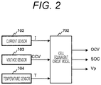
- a cell equivalent circuit model 702 obtained by modeling an equivalent circuit of the cell module 101 is stored in the battery controller 107 as illustrated in FIG. 2 .
- the battery controller 107 measures a current I, a CCV, and a temperature T of the cell module 101 using the current sensor 102, the voltage sensor 103, and the temperature sensor 104, respectively, and inputs these measurement results to the cell equivalent circuit model 702.
- the estimation of the internal state of the cell module 101 is realized by using the values of the OCV, the SOC, and the polarization voltage Vp output from the cell equivalent circuit model 702 depending on these input values as the internal state of the cell module 101.
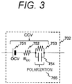
- FIG. 3 is a diagram illustrating a configuration example of the cell equivalent circuit model 702.
- the cell equivalent circuit model 702 consists of an ideal cell model 751 to calculate the OCV from the SOC, an internal resistance model 752 to calculate an internal resistance value RDC connected in series thereto, and a polarization model 755 to calculate the polarization voltage Vp.
- the polarization model 755 is expressed by connecting the polarization resistor 753 and a capacitor 754 in parallel.
- the cell equivalent circuit model 702 By configuring the cell equivalent circuit model 702 in this manner, it is possible to express various changes in cell voltage measured in the cell module 101, for example, a change depending on the SOC, a change depending on the flowing current, a change depending on the current history, and the like.
- the estimation of the OCV, the SOC, and Vp using the cell equivalent circuit model 702 can be performed, for example, by the following procedure.
- both the charge amount and the current I of the capacitor 754 are zero, and thus, the voltage generated by the internal resistance value RDC expressed by the internal resistance model 752 and the polarization voltage Vp also become zero.
- an OCV expressed by the ideal cell model 751 is equal to a CCV. Accordingly, an initial value of the OCV is obtained.
- an SOC corresponding to the initial value of the OCV is obtained using a correspondence table between the OCV and the SOC included in the battery controller 107, and this SOC is set as the initial SOC.
- the polarization voltage Vp is calculated by increasing or decreasing the charge amount of the capacitor 754 using the current I measured by the current sensor 102.
- the capacitor 754 has temperature dependence, and thus, it is preferable to calculate the polarization voltage Vp by adjusting characteristics of the capacitor 754 in accordance with the temperature T measured by using the temperature sensor 104.
- the characteristics of the capacitor 754 are set to be characteristics suitable for the present temperature T by using a temperature-time constant conversion table, a temperature-capacitor capacitance conversion table, or the like set in advance.
- the SOC is calculated by increasing or decreasing the charge amount stored in the cell using the current I measured by the current sensor 102.
- the estimation result of the OCV may be used for calculation of the SOC. That is, the OCV is estimated by subtracting the polarization voltage Vp and the voltage generated depending on the internal resistance value RDC from the CCV measured by the voltage sensor 103, and the SOC can be also estimated by reversely looking up the correspondence table between the OCV and the SOC.
- the cell equivalent circuit model 702 can be made equal to a present internal state of the cell module 101 by inputting the CCV, the current I, and the temperature T to the cell equivalent circuit model 702, and the OCV, the SOC, Vp can be estimated.
- the calculation of the polarization voltage Vp is simplified by expressing the polarization model 755 by a set of the polarization resistor 753 and the capacitor 754 in the example of FIG. 3 , but the number of sets of the polarization resistor and the capacitor expressing the polarization model 755 may be increased in order to improve the calculation accuracy.
- the charge amount of the capacitor 754 may be set to zero as necessary at the time of activating the cell system 100 or receiving an initialization command value from the host controller 112. It is preferably to set the charge amount of the capacitor 754 to be zero, for example, when a system stop time is sufficiently long relative to a time constant of the cell and it is possible to regard that the polarization is being resolved.
- a functional configuration of the battery controller 107 to calculate an allowable current will be described with reference to FIG. 4 .
- a phenomenon called a "high load resistance increase" in which an internal resistance of a cell temporarily increases when a large load is continuously applied to the cell occurs in the secondary cell such as the cell module 101.
- an appropriate allowable current is calculated in the battery controller 107 in accordance with a use state of the cell module 101 such that this high load resistance increase does not occur.
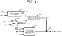
- FIG. 4 is a functional block diagram of the battery controller 107 relating to a process of calculating an allowable current according to a first embodiment of the present invention.
- the battery controller 107 according to the present embodiment includes each functional block of a ⁇ V effective value calculation unit 201, a ⁇ Vlimit database 202, a current restriction rate calculation unit 203, a cell protection allowable current calculation unit 204, and a multiplier 205.
- the battery controller 107 can realize these functional blocks, for example, by executing a predetermined program using a CPU.
- the battery controller 107 executes various types of processing and control relating to control of the cell system 100 in addition to the calculation of the allowable current of the cell module 101.
- the functional block diagram of FIG. 4 does not illustrate parts other than those necessary for the description of the present invention.
- the ⁇ V effective value calculation unit 201 calculates a ⁇ V effective value relating to a temporal change in a difference between the CCV and the OCV of the cell module 101.
- the ⁇ V effective value calculation unit 201 calculates the ⁇ V effective value by passing the difference between the CCV and the OCV of the cell module 101 through a filter including a lag element, for example. Specifically, it is possible to calculate the ⁇ V effective value in the ⁇ V effective value calculation unit 201 by applying a first-order lag filter to a value ( ⁇ V) obtained by squaring the difference between the CCV and the OCV of the cell module 101 and outputting a square root of the result reflecting the SOH as the ⁇ V effective value.
- Examples of calculation formulas of the ⁇ V effective value according to the ⁇ V effective value calculation unit 201 are expressed by the following Formulas (1) to (3).
- CCV(n) in Formula (1) represents a present CCV value of the cell module 101
- OCV(n) represents a present OCV value of the cell module 101.
- n in CCV(n) and OCV(n) represents a time sequence of CCV and OCV data acquired from the voltage sensor 103.
- t in Formula (2) represents a sampling interval of data
- ⁇ represents a time constant of the filter.
- SOHR in Formula (3) is an index indicating a degradation state of the cell module 101, and represents how much proportion the internal resistance accounts for with respect to the initial state. That is, the SOHR is 100% when the cell module 101 is new, and the SOHR increases with the degradation.
- V n CCV n ⁇ OCV n 2
- Formula (1) is a formula to calculate an index value ⁇ V(n) indicating a magnitude of a load of the cell module 101.
- CCV(n) - OCV(n) which is the difference between the CCV and the OCV, represents a magnitude of a present load of the cell module 101. This value can be used as an index for determination on whether the cell module 101 is in a state where the above-described high load resistance increase is likely to occur.
- the index value ⁇ V(n) is calculated by squaring CCV(n) - OCV(n). In this manner, it is possible to deal with both charging and discharging.
- Formula (2) is a formula to calculate an index value Y(n) indicating a temporal change of a load state of the cell module 101 by applying the first-order lag filter to ⁇ V(n) obtained by the Formula (1). With the calculation of Formula (2), it is possible to obtain an index value Y(n) indicating whether a high load state, that is, a state where ⁇ V(n) is a large value has occurred over a long time in the cell module 101.
- Formula (3) is a formula to calculate the ⁇ V effective value by reflecting the SOHR on the index value Y(n) of the temporal change of the load state obtained by Formula (2). With the calculation of Formula (3), it is also possible to deal with a change in ⁇ V(n) caused by a change in the internal resistance depending on the degradation of the cell module 101.
- the ⁇ V effective value calculation unit 201 can obtain the ⁇ V effective value relating to the temporal change of the difference between the CCV and the OCV of the cell module 101 by executing the above-described calculation.
- the ⁇ V effective value obtained in this manner is a value reflecting any magnitude of the load that is applied to the cell module 101 for any period of time.
- the ⁇ V effective value can be used as an index for determination on whether the allowable current calculation in consideration of a high load resistance increase is necessary.
- the calculation example using the first-order lag filter having a small calculation amount has been described in the present embodiment, but the ⁇ V effective value may be obtained using other calculation methods.
- high-accuracy calculation may be realized by using an FIR filter or a movement average to exclude data, obtained before a certain period or more, that does not affect the occurrence of the high load resistance increase from calculation.
- the ⁇ Vlimit database 202 is a database in which a relationship between the SOC and the temperature T of the cell module 101 and ⁇ Vlimit which is a limit value with respect to the difference between the CCV and the OCV of the cell module 101 is recorded. It is possible to determine ⁇ Vlimit as the limit value for prevention of the high load resistance increase by using the ⁇ Vlimit database 202 based on the SOC obtained from the cell equivalent circuit model 702 and the temperature T measured using the temperature sensor 104.
- ⁇ Vlimit represents the difference between the OCV and the CCV that is allowed within a certain time, that is, a limit value of the load.
- the ⁇ Vlimit database 202 can be realized by, for example, an array in which values of ⁇ Vlimit, respectively, corresponding to various combinations of the SOC and the temperature T are stored.
- the value of ⁇ Vlimit stored in the ⁇ Vlimit database 202 with respect to measurement results of the SOC and the temperature T of continuous values corresponds to the SOC and the temperature T of discrete values.
- the current restriction rate calculation unit 203 calculates the restriction rate k based on a relationship between the ⁇ V effective value and the restriction rate k as illustrated in FIG. 5 , for example.
- the region 232 is further divided into a region 233 ( ⁇ Vlimit1 ⁇ ⁇ V effective value ⁇ ⁇ Vlimit2) where the restriction rate k changes in accordance with the ⁇ V effective value and a region 234 ( ⁇ V effective value ⁇ ⁇ Vlimit2) where the restriction rate k is a fixed value kmin.
- the above-described ⁇ Vlimit2 is set to the magnitude of the ⁇ V effective value at which the high load resistance increase begins in the cell module 101, that is, the limit value ⁇ Vlimit determined using the ⁇ Vlimit database 202, and further ⁇ Vlimit1 is set to a value smaller than this ⁇ Vlimit.
- the restriction rate k is set to a value smaller than one.
- the current restriction rate calculation unit 203 may calculate the restriction rate k based on a relationship between the ⁇ V effective value and the restriction rate k as illustrated in FIG. 6 .
- normalization is performed by dividing the ⁇ V effective value by ⁇ Vlimit, and values corresponding to ⁇ Vlimit1 and ⁇ Vlimit2 in FIG. 5 are set to fixed values, respectively.
- a portion in which the ⁇ V effective value/ ⁇ Vlimit is 100% to 120% is set as a region 233 where the restriction rate k changes in accordance with the above-described ⁇ V effective value, and previous and subsequent regions thereof are set as the above-described regions 231 and 234, respectively.
- the cell protection allowable current calculation unit 204 calculates a cell protection allowable current to protect the cell module 101 based on the values of the SOC, the OCV, the polarization voltage Vp, the temperature T, and the current I output from the cell equivalent circuit model 702, the temperature sensor 104, and the current sensor 102. This allowable current satisfies a CCV restriction range, a temperature use range, and the like of the cell module 101. Incidentally, a specific calculation method of the cell protection allowable current by the cell protection allowable current calculation unit 204 will be described later with reference to FIG. 7 .
- the multiplier 205 calculates the allowable current of the cell module 101 based on the restriction rate k calculated by the current restriction rate calculation unit 203 and the cell protection allowable current calculated by the cell protection allowable current calculation unit 204. Specifically, the multiplier 205 multiplies a value of the cell protection allowable current by the restriction rate k, thereby realizing the restriction on the allowable current in accordance with the restriction rate k, that is, the allowable current in accordance with the ⁇ V effective value.
- the allowable current is maximized by using the cell protection allowable current directly as the allowable current without restriction.
- the ⁇ V effective value is large, that is, when a large load is applied to the cell module 101 for a long time, the occurrence of high load resistance increase is prevented by restricting the allowable current.
- FIG. 7 is a functional block diagram of the cell protection allowable current calculation unit 204 according to the first embodiment of the present invention.
- the cell protection allowable current calculation unit 204 consists of a cell parameter database 703, a calculation block 704 that calculates an allowable current when there is no polarization, a prediction block 705 that predicts polarization after a certain time, a correction block 706 that calculates a value of correcting influence caused by polarization, and a subtractor 707 that applies the correction.
- the database 703 outputs upper and lower limit voltages, a first resistance, and a first gain necessary for calculation of the allowable current based on the SOC output from the cell equivalent circuit model 702, the temperature T output from the temperature sensor 104, and the current I output by the current sensor 102. As a result, it is possible to calculate the allowable current necessary for cell protection.
- the database 703 may be a database in which values of the SOC, the temperature T, and the current I and values of these output data are mapped in association with each other. In this manner, it is possible to reduce the amount of calculation and to deal with a characteristic whose theoretical formula is unknown.
- a database in which relationships among the values of the SOC, the temperature T, and the current I and the values of these output data are expressed by an approximation formula may be used as the database 703. As a result, it is possible to reduce the amount of data and to improve the accuracy of an output value.
- an allowable current at the time of non-polarization is calculated based on the OCV output from the cell equivalent circuit model 702, the upper and lower limit voltages and the first resistance output from the database 703.
- Imax represents an allowable charge current at the time of non-polarization
- Vmax represents an upper limit voltage
- R1 represents the first resistance.
- the formula for obtaining the allowable charge current at the time of non-polarization is exemplified in Formula (4), but an allowable discharge current at the time of non-polarization can be also obtained with the same calculation by using a lower limit voltage Vmin instead of the upper limit voltage Vmax.
- the upper limit voltage Vmax and the lower limit voltage Vmin can be obtained based on the upper and lower limit voltages output from the database 703.
- only one of the upper limit voltage Vmax and the lower limit voltage Vmin may be determined in the database 703, and only one of the allowable charge current and the allowable discharge current at the time of non-polarization may be calculated in the calculation block 704 based on such a determined value.
- the allowable charge current Imax at the time of non-polarization obtained by Formula (4) becomes a current value to reach the upper limit voltage after a certain time from the non-polarized state, that is, a current value not to reach the upper limit voltage within a certain time.
- the allowable current in the case where there is no polarization can be calculated by using the OCV, the upper and lower limit voltages, and the first resistance in this manner.
- a first polarization voltage which is a polarization voltage after a certain time (assumed to be after n seconds) is predicted and output based on the polarization voltage Vp output from the cell equivalent circuit model 702 and the first gain output from the database 703.
- the prediction block 705 can predict the polarization voltage after n seconds when a constant current flows by using the following Formula (5) employing an exponential function, for example.
- Vpn IRp ⁇ IRp ⁇ Vp 0 exp ⁇ n / RpCp
- Vpn the polarization voltage after n seconds
- Rp a polarization resistance
- I the current
- Vp0 a present polarization voltage
- Cp a polarization capacitor.
- Formula (5) can be transformed as the following Formula (6).
- Vpn IRp ⁇ IRp ⁇ Vp 0 Gt
- Gt is the first gain.
- an allowable current correction value in consideration of the influence of the polarization voltage on the allowable current is calculated based on polarization information and the first resistance output from the database 703.
- the first polarization voltage output from the prediction block 705 can be used as the polarization information.
- the polarization voltage Vp output from the cell equivalent circuit model 702 may be directly used although different from the configuration of FIG. 7 . In this case, the polarization voltage is estimated to be relatively large, the calculated allowable current value becomes small, but safety can be more reliably secured.
- the correction amount of the influence caused by the polarization can be calculated by dividing the polarization information by the first resistance output from the database 703.
- the polarization voltage may be multiplied by a fixed value and used. In this manner, it is possible to adjust the degree of influence of the polarization voltage, and thus, it is possible to prevent overvoltage caused by an estimation error of the polarization voltage in the cell equivalent circuit model 702.
- the subtractor 707 subtracts the allowable current correction value output by the correction block 706 from the allowable current at the time of non-polarization output by the calculation block 704, thereby performing the allowable current correction in consideration of the influence of the polarization voltage.
- the largest current with which the CCV does not reach the upper limit voltage or the lower limit voltage even if being caused to flow to the cell module 101 for a certain time, that is, the cell protection allowable current can be calculated.
- the value of the first resistance may be obtained based on a DC resistance (DCR) of the cell module 101, a second gain which is a change rate of the OCV per unit current, the polarization resistance, and the first gain, instead of directly outputting the value of the first resistance from the database 703 as described above.
- DCR DC resistance
- the value of the first resistance can be calculated using the following Formula (7).
- R 1 DCR + Gsoc + Rp 1 ⁇ G 1
- R1 represents the first resistance
- Gsoc represents the second gain
- Rp represents the polarization resistance
- G1 represents the first gain.
- the cell protection allowable current calculation unit 204 can calculate the cell protection allowable current by the calculation method as described above.
- the battery controller 107 performs the allowable current calculation process with the above-described configuration so that it is possible to calculate the ⁇ V effective value, which is the index value for determination on whether it is necessary to consider the high load resistance increase and to restrict the allowable current based on the calculated ⁇ V effective value.
- the ⁇ V effective value which is the index value for determination on whether it is necessary to consider the high load resistance increase
- the allowable current based on the calculated ⁇ V effective value.
- a configuration different from the configuration that has been described in the first embodiment will be described as a functional configuration of the battery controller 107 to calculate an allowable current that can be caused to flow to the cell module 101 for a certain time while considering the high load resistance increase.
- FIG. 8 is a functional block diagram of the battery controller 107 relating to a process of calculating an allowable current according to the second embodiment of the present invention.
- the common parts to those in the functional block diagram of FIG. 4 that have been already described in the first embodiment are denoted by the same reference signs as those in FIG. 4 .
- the common parts will not be described hereinafter unless particularly necessary.
- the battery controller 107 of the present embodiment includes a performance maintenance allowable current calculation unit 211 and a minimum value selector 212 instead of the current restriction rate calculation unit 203 and the multiplier 205 in FIG. 4 .
- the battery controller 107 can realize these functional blocks, for example, by executing a predetermined program using a CPU.
- the performance maintenance allowable current calculation unit 211 calculates a performance maintenance allowable current to maintain the performance of the cell module 101 based on a ⁇ V effective value output from the ⁇ V effective value calculation unit 201, ⁇ Vlimit output from the ⁇ Vlimit database 202, and values of an SOC, a temperature T, and an SOHR output from the cell equivalent circuit model 702 and the temperature sensor 104. This allowable current is configured to prevent occurrence of the high load resistance increase in the cell module 101.
- the minimum value selector 212 calculates the allowable current of the cell module 101 based on the performance maintenance allowable current output from the performance maintenance allowable current calculation unit 211 and a cell protection allowable current output from the cell protection allowable current calculation unit 204. Specifically, the minimum value selector 212 compares these allowable currents and selects and outputs a smaller one therebetween as the allowable current.
- Formula (2) can be simplified as the following Formula (8).
- m in Formula (2) represents a constant time that needs to be considered in allowable current calculation
- a and B represent constants which are determined based on ⁇ , t, and m.
- ⁇ V can be expressed by the following Formula (10)
- the current value I can be obtained by the following Formula (11) from Formula (10) and the above-described Formula (9).
- the values of the internal resistance value RDC and the polarization resistor Rp can be determined by the SOC and the temperature T.
- the current value I obtained by the above-described Formula (11) indicates a value with which the effective value of ⁇ V becomes equal to the ⁇ Vlimit when being caused to continuously flow to the cell module 101 for a certain time. Therefore, the magnitude of the current determined by the current value I becomes the allowable current to prevent the occurrence of the high load resistance increase in the cell module 101, that is, the performance maintenance allowable current.
- the performance maintenance allowable current calculation unit 211 can calculate the performance maintenance allowable current by the calculation method as described above.
- the battery controller 107 performs the allowable current calculation process with the above-described configuration so that each of the performance maintenance allowable current to prevent the occurrence of the high load resistance increase in the cell module 101 estimated from the present ⁇ V effective value and the cell protection allowable current to realize the protection of the cell module 101 is calculated. Then, a smaller one between these allowable currents is selected. As a result, it is possible to simultaneously prevent the high load resistance increase and protect the cell by restricting the allowable current for cell protection and outputting the restricted allowable current as the final allowable current.
- the current value with which the ⁇ V effective value becomes equal to the ⁇ Vlimit when being caused to continuously flow to the cell module 101 for a certain time is obtained in the calculation of the performance maintenance allowable current.
- This current value has a value larger than the cell protection allowable current under a condition where the high load resistance increase does not occur, that is, under a condition corresponding to the region 231 in FIG. 5 .
- it is possible to increase the allowable current by making the allowable current in the case where it is unnecessary to consider the high load resistance increase equal to the cell protection allowable current, which is similar to the first embodiment.
- the performance maintenance allowable current in consideration of the high load resistance increase becomes smaller under a condition corresponding to the region 232 in FIG.
- the above-described Formula (11) is calculation including a square root, and thus, the calculation becomes complicated as compared with the first embodiment in which the restriction rate k of the allowable current is calculated based on the relationship between the ⁇ V effective value and the restriction rate k as illustrated in FIGS. 5 and 6 .
- FIG. 9 is a functional block diagram of the battery controller 107 relating to a process of calculating an allowable current according to the third embodiment of the present invention.
- the common parts to those in the functional block diagrams of FIGS. 4 and 8 that have been already described in the first and second embodiments are denoted by the same reference signs as those in FIGS. 4 and 8 .
- the common parts will not be described hereinafter unless particularly necessary.
- the battery controller 107 of the present embodiment includes a weight calculation unit 221 and a weighting calculation unit 222 in addition to the ⁇ V effective value calculation unit 201, the ⁇ Vlimit database 202, and the cell protection allowable current calculation unit 204, which have been described in the first embodiment, and the performance maintenance allowable current calculation unit 211 which has been described in the second embodiment.
- the battery controller 107 can realize these functional blocks, for example, by executing a predetermined program using a CPU.
- a ⁇ V effective value is not input from the ⁇ V effective value calculation unit 201 to the performance maintenance allowable current calculation unit 211.
- the performance maintenance allowable current calculation unit 211 calculates a performance maintenance allowable current by the calculation method as described in the second embodiment by using ⁇ Vlimit instead of the ⁇ V effective value.
- ⁇ Vlimit instead of the ⁇ V effective value.
- an allowable current in the case where the ⁇ V effective value is equal to the ⁇ Vlimit is output from the performance maintenance allowable current calculation unit 211 as the performance maintenance allowable current.
- the performance maintenance allowable current obtained in this manner is used, it is possible to perform control in consideration of the high load resistance increase by preventing the ⁇ V effective value from exceeding ⁇ Vlimit.
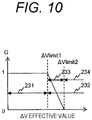
- the weight calculation unit 221 calculates a weight G for the performance maintenance allowable current and a cell protection allowable current based on the ⁇ V effective value output from the ⁇ V effective value calculation unit 201 and the ⁇ Vlimit output from the ⁇ Vlimit database 202.
- a value of the weight G changes between zero and one in accordance with the ⁇ V effective value and the ⁇ Vlimit value.
- the weight calculation unit 221 calculates the weight G based on a relationship between the ⁇ V effective value and the weight G as illustrated in FIG. 10 , for example.
- the region 232 is further divided into a region 233 ( ⁇ Vlimit1 ⁇ ⁇ V effective value ⁇ ⁇ Vlimit2) where the weight G changes between one and zero in accordance with the ⁇ V effective value and a region 234 ( ⁇ V effective value ⁇ ⁇ Vlimit2) where the weight G is zero.
- the battery controller 107 performs the allowable current calculation process with the above-described configuration so that it is possible to output the value between the cell protection allowable current and the performance maintenance allowable current, as the allowable current, in accordance with the ⁇ V effective value.
- the allowable current is obtained by multiplying the cell protection allowable current by the restriction rate k in the first embodiment.
- the allowable current is restricted using the performance maintenance allowable current in the present embodiment although the amount of calculation increases.
- the allowable current is set to a value equal to the performance maintenance allowable current at the minimum, that is, a value equal to the maximum current capable of maintaining the cell performance. As a result, it is possible to expect an increase in the allowable current.
- FIG. 11 is a functional block diagram of the battery controller 107 relating to a process of calculating the allowable current according to the fourth embodiment of the present invention.
- the common parts to those in the functional block diagrams of FIGS. 4 , 8 , and 9 that have been already described in the first to third embodiments are denoted by the same reference signs as those in FIGS. 4 , 8 , and 9 .
- the common parts will not be described hereinafter unless particularly necessary.
- the battery controller 107 of the present embodiment includes the ⁇ Vlimit database 202 that has been described in the first embodiment and a cell model-based performance maintenance and cell protection allowable current calculation unit 226.
- the battery controller 107 can realize these functional blocks, for example, by executing a predetermined program using a CPU.
- the performance maintenance and cell protection allowable current calculation unit 226 calculates an allowable current for performance maintenance and protection of the cell module 101.
- the performance maintenance and cell protection allowable current calculation unit 226 performs this allowable current calculation using the calculation method as described above based on ⁇ Vlimit output from the ⁇ Vlimit database 202 and values of an SOC, an OCV, a polarization voltage Vp, a temperature T, and a current I output from the cell equivalent circuit model 702, the temperature sensor 104, and the current sensor 102.
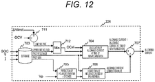
- FIG. 12 is a functional block diagram of the performance maintenance and cell protection allowable current calculation unit 226 according to the fourth embodiment of the present invention. As illustrated in FIG. 12 , the performance maintenance and cell protection allowable current calculation unit 226 includes an adder 711 and a minimum value selector 712 in addition to the respective configurations of the cell protection allowable current calculation unit 204 that has been described in FIG. 7 in the first embodiment.
- the adder 711 calculates a limit voltage of the cell module 101 based on the ⁇ Vlimit and the OCV. Specifically, the adder 711 outputs a value obtained by adding the ⁇ Vlimit and the OCV as the limit voltage which is an upper limit value of a CCV to prevent occurrence of the high load resistance increase in the cell module 101. With this limit voltage, the upper limit of the CCV that does not cause the high load resistance increase is determined.
- the OCV is added to the ⁇ Vlimit in the above-described example, but the CCV may be used instead of the OCV. In this case, it is preferable to output a value obtained by adding the CCV to the ⁇ Vlimit and then subtracting a polarization voltage or a voltage drop caused by a DC resistance from the added result as a limit voltage.
- the minimum value selector 712 calculates a voltage upper limit to calculate the allowable current of the cell module 101 based on the limit voltage output from the adder 711 and an upper limit voltage output from the database 703. Specifically, the minimum value selector 712 compares the limit voltage and the upper limit voltage, and selects and outputs a smaller one therebetween as a voltage upper limit value. In this manner, a value of the CCV that does not cause the high load resistance increase and does not deviate from the upper limit voltage of the cell is obtained by restricting the upper limit voltage using the limit voltage output by the adder 711.
- the calculation block 704 can calculate an allowable current at the time of non-polarization by using the calculation method as described above. That is, in the cell protection allowable current calculation unit 204 in the first embodiment, the values of the OCV, the upper and lower limit voltages, and the first resistance are input to the calculation block 704, and the calculation block 704 obtains the allowable current at the time of non-polarization based on these values as illustrated in FIG. 7 . On the other hand, in the present embodiment, the output of the minimum value selector 712 is input to the calculation block 704 instead of the upper and lower limit voltages, and the calculation block 704 uses this output to obtain the allowable current at the time of non-polarization.
- the performance maintenance and cell protection allowable current calculation unit 226 calculates a final allowable current based on the allowable current at the time of non-polarization. As a result, a value of the allowable current that does not cause the high load resistance increase and does not deviate from the upper limit voltage of the cell is obtained.
- the adder 711 adds the ⁇ Vlimit to the OCV to obtain the limit voltage, and the minimum value selector 712 compares the limit voltage and the upper limit voltage to obtain the voltage upper limit value in the above description.
- the final allowable current obtained by the performance maintenance and cell protection allowable current calculation unit 226 is an allowable current at the time of charging the cell module 101, that is, an allowable charge current.
- the adder 711 may be replaced with a subtractor and the minimum value selector 712 may be replaced with a maximum value selector in the performance maintenance and cell protection allowable current calculation unit 226.
- the subtractor subtracts the ⁇ Vlimit from the OCV to obtain the limit voltage
- the maximum value selector compares the limit voltage with the lower limit voltage to obtain a voltage lower limit value, which is contrary to the above description.
- the final allowable current obtained by the performance maintenance and cell protection allowable current calculation unit 226 is an allowable current at the time of discharging the cell module 101, that is, an allowable discharge current. In this manner, a value of the allowable current that does not cause the high load resistance increase and does not deviate from the lower limit voltage of the cell is obtained.
- the performance maintenance and cell protection allowable current calculation unit 226 may be configured to obtain both the allowable charge current and the allowable discharge current.
- the battery controller 107 performs the allowable current calculation process with the above-described configuration so that it is possible to collectively calculate the allowable current that realizes both the protection and performance maintenance of the cell and to reduce the amount of calculation.
- FIG. 13 is a functional block diagram of the battery controller 107 relating to a process of calculating the allowable current according to the fifth embodiment of the present invention.
- the common parts to those in the functional block diagrams of FIGS. 4 , 8 , 9 , and 11 that have been already described in the first to fourth embodiments are denoted by the same reference signs as those in FIGS. 4 , 8 , 9 , and 11 .
- the common parts will not be described hereinafter unless particularly necessary.
- the battery controller 107 of the present embodiment includes the ⁇ V effective value calculation unit 201, the ⁇ Vlimit database 202, and the current restriction rate calculation unit 203, which have been described in the first embodiment, and a cell model-based performance maintenance and cell protection allowable current calculation unit 227.
- the battery controller 107 can realize these functional blocks, for example, by executing a predetermined program using a CPU.
- the performance maintenance and cell protection allowable current calculation unit 227 calculates an allowable current for performance maintenance and protection of the cell module 101, which is similar to the performance maintenance and cell protection allowable current calculation unit 226 of FIG. 11 that has been described in the fourth embodiment.
- the performance maintenance and cell protection allowable current calculation unit 227 performs this allowable current calculation using the calculation method as described above based on a restriction rate k output from the current restriction rate calculation unit 203 and values of an SOC, an OCV, a polarization voltage Vp, a temperature T, and a current I output from the cell equivalent circuit model 702, the temperature sensor 104, and the current sensor 102.
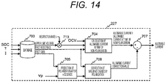
- FIG. 14 is a functional block diagram of the performance maintenance and cell protection allowable current calculation unit 227 according to the fifth embodiment of the present invention. As illustrated in FIG. 14 , the performance maintenance and cell protection allowable current calculation unit 227 has a configuration in which the adder 711 and the minimum value selector 712 are replaced with a multiplier 713 in the performance maintenance and cell protection allowable current calculation unit 226 of FIG. 12 that has been described in the fourth embodiment.
- the multiplier 713 multiplies an upper limit voltage output from the database 703 by the restriction rate k to restrict the upper limit voltage in accordance with the restriction rate k, and outputs the upper limit value of the CCV that does not cause the high load resistance increase. As a result, a voltage upper limit value that does not cause the high load resistance increase and does not deviate from the upper limit voltage of the cell is obtained. In addition, it is possible to restrict the upper limit voltage in accordance with the restriction rate k by using the ⁇ V effective value only when it is necessary to restrict the upper limit voltage in order to prevent the high load resistance increase.
- the calculation block 704 can calculate an allowable current at the time of non-polarization by using the calculation method as described above. That is, in the cell protection allowable current calculation unit 204 in the first embodiment, the values of the OCV, the upper and lower limit voltages, and the first resistance are input to the calculation block 704, and the calculation block 704 obtains the allowable current at the time of non-polarization based on these values as illustrated in FIG. 7 . On the other hand, in the present embodiment, the output of the multiplier 713 is input to the calculation block 704 instead of the upper and lower limit voltages, and the calculation block 704 uses this output to obtain the allowable current at the time of non-polarization.
- the performance maintenance and cell protection allowable current calculation unit 227 calculates a final allowable current based on the allowable current at the time of non-polarization. As a result, a value of the allowable current that does not cause the high load resistance increase and does not deviate from the upper limit voltage of the cell is obtained.
- the voltage upper limit value is obtained by multiplying the upper limit voltage by the restriction rate k using the multiplier 713 in the above description.
- the final allowable current obtained by the performance maintenance and cell protection allowable current calculation unit 227 is an allowable current at the time of charging the cell module 101, that is, an allowable charge current.
- a limit voltage may be obtained by subtracting ⁇ Vlimit from the OCV using the multiplier 713, and a voltage lower limit value may be obtained by multiplying the lower limit voltage by the restriction rate k using a maximum value selector in the performance maintenance and cell protection allowable current calculation unit 227, which is contrary to the above description.
- the final allowable current obtained by the performance maintenance and cell protection allowable current calculation unit 227 is an allowable current at the time of discharging the cell module 101, that is, an allowable discharge current. In this manner, a value of the allowable current that does not cause the high load resistance increase and does not deviate from the lower limit voltage of the cell is obtained. Further, the performance maintenance and cell protection allowable current calculation unit 227 may be configured to obtain both the allowable charge current and the allowable discharge current.
- the battery controller 107 performs the allowable current calculation process with the above-described configuration so that it is possible to collectively calculate the allowable current that realizes both the protection and performance maintenance of the cell and to reduce the amount of calculation, which is similar to the fourth embodiment.
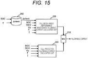
- FIG. 15 is a functional block diagram of the battery controller 107 relating to a process of calculating the allowable current according to the sixth embodiment of the present invention.
- the common parts to those in the functional block diagrams of FIGS. 4 , 8 , 9 , 11 , and 13 that have been already described in the first to fifth embodiments are denoted by the same reference signs as those in FIGS. 4 , 8 , 9 , 11 , and 13 .
- the common parts will not be described hereinafter unless particularly necessary.
- the battery controller 107 of the present embodiment includes the ⁇ Vlimit database 202 and the cell protection allowable current calculation unit 204, which have been described in the first embodiment, the minimum value selector 212, which has been described in the second embodiment, and a cell model-based performance maintenance allowable current calculation unit 228.
- the battery controller 107 can realize these functional blocks, for example, by executing a predetermined program using a CPU.
- the performance maintenance allowable current calculation unit 228 calculates a performance maintenance allowable current to maintain performance of the cell module 101 similarly to the performance maintenance allowable current calculation unit 211 that has been described in the second embodiment.
- the performance maintenance allowable current calculation unit 228 performs the calculation of the performance maintenance allowable current using the calculation method as described above based on ⁇ Vlimit output from the ⁇ Vlimit database 202 and values of an SOC, an OCV, the polarization voltage Vp, a temperature T, and a current I output from the cell equivalent circuit model 702, the temperature sensor 104, and the current sensor 102. Then, the calculated performance maintenance allowable current is output to the minimum value selector 212.
- the minimum value selector 212 calculates the allowable current of the cell module 101 based on the performance maintenance allowable current output from the performance maintenance allowable current calculation unit 228 and a cell protection allowable current output from the cell protection allowable current calculation unit 204, which is similar to the second embodiment. That is, the minimum value selector 212 compares these allowable currents and selects and outputs a smaller one therebetween as the allowable current.
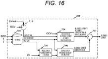
- FIG. 16 is a functional block diagram of the performance maintenance allowable current calculation unit 228 according to the sixth embodiment of the present invention. As illustrated in FIG. 16 , the performance maintenance allowable current calculation unit 228 includes the adder 711 in addition to the respective configurations of the cell protection allowable current calculation unit 204 that has been described in FIG. 7 in the first embodiment.
- the adder 711 calculates a limit voltage of the cell module 101 based on the ⁇ Vlimit and the OCV similarly to the description in the fourth embodiment. That is, the adder 711 outputs a value obtained by adding the ⁇ Vlimit and the OCV as the limit voltage which is an upper limit value of a CCV to prevent occurrence of the high load resistance increase in the cell module 101. With this limit voltage, the upper limit of the CCV that does not cause the high load resistance increase is determined.
- the OCV is added to the ⁇ Vlimit in the above-described example, but the CCV may be used instead of the OCV. In this case, it is preferable to output a value obtained by adding the CCV to the ⁇ Vlimit and then subtracting a polarization voltage or a voltage drop caused by a DC resistance from the added result as a limit voltage.
- the calculation block 704 can calculate an allowable current at the time of non-polarization by using the calculation method as described above. That is, in the cell protection allowable current calculation unit 204 in the first embodiment, the values of the OCV, the upper and lower limit voltages, and the first resistance are input to the calculation block 704, and the calculation block 704 obtains the allowable current at the time of non-polarization based on these values as illustrated in FIG. 7 . On the other hand, in the present embodiment, the limit voltage output from the adder 711 instead of the upper and lower limit voltage is input to the calculation block 704, and the calculation block 704 uses this limit voltage to obtain the allowable current at the time of non-polarization.
- the performance maintenance allowable current calculation unit 228 calculates the performance maintenance allowable current based on the allowable current at the time of non-polarization. As a result, a value of the allowable current that does not cause the high load resistance increase and does not deviate from the upper limit voltage of the cell is obtained in consideration of the present polarization voltage Vp.
- the adder 711 adds the ⁇ Vlimit to the OCV to obtain the limit voltage in the above description.
- the performance maintenance allowable current obtained by the performance maintenance allowable current calculation unit 228 is an allowable current at the time of charging the cell module 101, that is, an allowable charge current.
- the adder 711 may be replaced with a subtractor in the performance maintenance allowable current calculation unit 228.
- the limit voltage is obtained by subtracting the ⁇ Vlimit from the OCV using the subtractor, which is contrary to the above description.
- the performance maintenance allowable current obtained by the performance maintenance allowable current calculation unit 228 is an allowable current at the time of discharging the cell module 101, that is, an allowable discharge current.
- the performance maintenance allowable current calculation unit 228 may be configured to obtain both the allowable charge current and the allowable discharge current.
- the battery controller 107 performs the allowable current calculation process with the above-described configuration so that it is possible to consider the influence of the polarization voltage, which necessarily accompanies charging and discharging of the cell module 101, on the allowable current. Thus, it is possible to more accurately calculate the allowable current which does not cause the high load resistance increase.
- a seventh embodiment of the present invention will be described.
- a description will be given regarding an example in which a polarization voltage Vp is taken into consideration in calculating the performance maintenance allowable current that has been described in the third embodiment.
- FIG. 17 is a functional block diagram of the battery controller 107 relating to a process of calculating the allowable current according to the seventh embodiment of the present invention.
- the common parts to those in the functional block diagrams of FIGS. 4 , 8 , 9 , 11 , 13 , and 15 that have been already described in the first to sixth embodiments are denoted by the same reference signs as those in FIGS. 4 , 8 , 9 , 11 , 13 , and 15 .
- the common parts will not be described hereinafter unless particularly necessary.
- the battery controller 107 of the present embodiment includes the ⁇ V effective value calculation unit 201, the ⁇ Vlimit database 202, and the cell protection allowable current calculation unit 204, which have been described in the first embodiment, the weight calculation unit 221 and the weighting calculation unit 222, which have been described in the third embodiment, and the cell model-based performance maintenance allowable current calculation unit 228 which has been described in the sixth embodiment.
- the battery controller 107 can realize these functional blocks, for example, by executing a predetermined program using a CPU.
- the battery controller 107 performs the allowable current calculation process with the above-described configuration so that it is possible to output the value between the cell protection allowable current and the performance maintenance allowable current, as the allowable current, in accordance with the ⁇ V effective value, which is similar to the third embodiment.
- the polarization voltage necessarily accompanying charging and discharging of the cell module 101 on the allowable current, which is similar to the sixth embodiment.
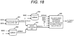
- FIG. 18 is a functional block diagram of the battery controller 107 relating to a process of calculating the allowable current according to the eighth embodiment of the present invention.
- the common parts to those in the functional block diagrams of FIGS. 4 , 8 , 9 , 11 , 13 , 15 , and 17 that have been already described in the first to seventh embodiments are denoted by the same reference signs as those in FIGS. 4 , 8 , 9 , 11 , 13 , 15 , and 17 .
- the common parts will not be described hereinafter unless particularly necessary.
- the battery controller 107 of the present embodiment includes the ⁇ V effective value calculation unit 201 and the ⁇ Vlimit database 202, which have been described in the first embodiment, the weight calculation unit 221, which has been described in the third embodiment, and a cell model-based performance maintenance and cell protection allowable current calculation unit 229.
- the battery controller 107 can realize these functional blocks, for example, by executing a predetermined program using a CPU.
- the performance maintenance and cell protection allowable current calculation unit 229 calculates an allowable current for performance maintenance and protection of the cell module 101, which is similar to the performance maintenance and cell protection allowable current calculation unit 226 of FIG. 11 that has been described in the fourth embodiment and the performance maintenance and cell protection allowable current calculation unit 227 of FIG. 13 that has been described in the fifth embodiment.
- the performance maintenance and cell protection allowable current calculation unit 229 performs this allowable current calculation using the calculation method as described above based on ⁇ Vlimit output from the ⁇ Vlimit database 202, a weight G output from the weight calculation unit 221, and values of an SOC, an OCV, the polarization voltage Vp, a temperature T, and a current I output from the cell equivalent circuit model 702, the temperature sensor 104, and the current sensor 102.
- FIG. 19 is a functional block diagram of the performance maintenance and cell protection allowable current calculation unit 229 according to the eighth embodiment of the present invention. As illustrated in FIG. 19 , the performance maintenance and cell protection allowable current calculation unit 229 has a configuration in which the minimum value selector 712 is replaced with a weighting calculator 714 in the performance maintenance and cell protection allowable current calculation unit 226 of FIG. 12 that has been described in the fourth embodiment.
- the calculation block 704 can calculate an allowable current at the time of non-polarization by using the calculation method as described above. That is, in the cell protection allowable current calculation unit 204 in the first embodiment, the values of the OCV, the upper and lower limit voltages, and the first resistance are input to the calculation block 704, and the calculation block 704 obtains the allowable current at the time of non-polarization based on these values as illustrated in FIG. 7 . On the other hand, in the present embodiment, the output of the weighting calculator 714 is input to the calculation block 704 instead of the upper and lower limit voltages, and the calculation block 704 uses this output to obtain the allowable current at the time of non-polarization.
- the performance maintenance and cell protection allowable current calculation unit 229 calculates a final allowable current based on the allowable current at the time of non-polarization. As a result, a value of the allowable current that does not cause the high load resistance increase and does not deviate from the upper limit voltage of the cell is obtained reflecting the ⁇ V effective value.
- the adder 711 adds the ⁇ Vlimit to the OCV to obtain the limit voltage, and the weighting calculator 714 performs the weighted averaging of the limit voltage and the upper limit voltage to obtain the target CCV in the above description.
- the final allowable current obtained by the performance maintenance and cell protection allowable current calculation unit 229 is an allowable current at the time of charging the cell module 101, that is, an allowable charge current.
- the adder 711 may be replaced with a subtractor in the performance maintenance and cell protection allowable current calculation unit 229.
- the subtractor subtracts the ⁇ Vlimit from the OCV to obtain the limit voltage
- the weighting calculator 714 performs weighted averaging of the limit voltage and the lower limit voltage to obtain the target CCV, which is contrary to the above description.
- the final allowable current obtained by the performance maintenance and cell protection allowable current calculation unit 229 is an allowable current at the time of discharging the cell module 101, that is, an allowable discharge current.
- the performance maintenance and cell protection allowable current calculation unit 229 may be configured to obtain both the allowable charge current and the allowable discharge current.
- the battery controller 107 performs the allowable current calculation process with the above-described configuration so that it is possible to collectively calculate the allowable current that realizes both the protection and performance maintenance of the cell while reflecting the ⁇ V effective value and to reduce the amount of calculation.
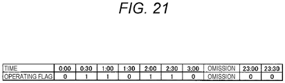
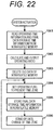
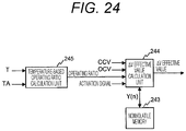
- the battery controller 107 is shut down when an ignition key of the vehicle is turned off in order to reduce power consumption. While the battery controller 107 is shut down, the first-order lag filter necessary for calculation of a ⁇ V effective value does not operate so that it is difficult to obtain the ⁇ V effective value by the calculation expressed by the above-described Formula (2) in the ⁇ V effective value calculation unit 201. Thus, exception processing to reflect a charge/discharge pause period caused by shutdown is required for calculation of the ⁇ V effective value at the next system activation. In the present embodiment, the ⁇ V effective value is calculated by performing calculation to be described below with reference to FIGS. 20 to 23 in the battery controller 107 in order to realize this exception processing.
- FIG. 20 is a functional block diagram of the battery controller 107 relating to a process of calculating the ⁇ V effective value according to the ninth embodiment of the present invention.
- the battery controller 107 of the present embodiment includes a date and time information generation unit 241, a date and time-based operating ratio calculation unit 242, a nonvolatile memory 243, and a ⁇ V effective value calculation unit 244.
- the battery controller 107 can realize these functional blocks, for example, by executing a predetermined program using a CPU.
- the battery controller 107 of the present embodiment calculates the ⁇ V effective value using a functional configuration illustrated in FIG. 20 instead of the ⁇ V effective value calculation unit 201 in FIGS.
- an allowable current is calculated by performing the calculation process as described in each of the first to third, fifth, seventh, and eighth embodiments based on the obtained calculation result of the ⁇ V effective value. This allowable current calculation process will not be described hereinafter.
- the date and time information generation unit 241 generates information indicating present date and time, and outputs the generated information as date and time information.
- the date and time information generation unit 241 can acquire the present date and time based on information transmitted from, for example, a real-time clock (not illustrated) mounted on the battery controller 107 and the host controller 112.
- the operating ratio calculation unit 242 calculates an operating ratio of the battery controller 107 on a date-and-time basis, based on the date and time information output from the date and time information generation unit 241, an activation signal of the vehicle transmitted from the host controller 112, and operating time information stored in the nonvolatile memory 243. Incidentally, a method of calculating the operating ratio by the operating ratio calculation unit 242 will be described in detail later.
- the nonvolatile memory 243 stores the operating time information indicating past operating history of the battery controller 107, final Y(n), and the like.
- the final Y(n) is the index value Y(n) relating to the temporal change of the load state of the cell module 101 that has been obtained last during the previous system operation, and is expressed by the above-described Formula (2).
- the operating time information is stored in the nonvolatile memory 243 by the operating ratio calculation unit 242 and is read from the nonvolatile memory 243, and the final Y(n) is stored in the nonvolatile memory 243 by the ⁇ V effective value calculation unit 244 and is read from the nonvolatile memory 243.
- FIG. 21 is a diagram illustrating an example of the operating time information stored in the nonvolatile memory 243.
- an operating flag indicating an operating status of the battery controller 107 every 30 minutes is stored as the past operating history of the battery controller 107 in the nonvolatile memory 243.
- one day is divided into time zones every 30 minutes, that is, 48 time zones, a flag value "1" when the battery controller 107 is operating or a flag value "0" when the battery controller 107 is no operating is stored as the operating flag in each time zone. Since the flag value "1" indicating the status in the middle of operating is present at four places in the range illustrated in FIG.
- the ⁇ V effective value calculation unit 244 calculates the ⁇ V effective value based on the operating ratio output from the operating ratio calculation unit 242, a CCV and an OCV of the cell module 101, the activation signal indicating a state of the vehicle, and the final Y(n) read from the nonvolatile memory 243.
- a method of calculating the ⁇ V effective value by the ⁇ V effective value calculation unit 244 will be described in detail later.
- FIG. 22 is a diagram illustrating a processing flow of the operating ratio calculation unit 242 according to the ninth embodiment of the present invention.
- the operating ratio calculation unit 242 reads the operating time information and the final data storage time information stored in the nonvolatile memory 243 from the nonvolatile memory 243 in Step 1001.
- step 1002 the operating ratio calculation unit 242 obtains the proportion of the operating time in the past 24 hours based on the proportion of the operating flag value "1" in the operating time information read in step 1001 to calculate the operating ratio of the battery controller 107. Then, the calculated operating ratio is output to the ⁇ V effective value calculation unit 244.
- it is preferable to determine which data among the operating time information is data within the past 24 hours from the present time and to select only such data as a calculation target based on the final data storage time read in step 1001. As a result, information that is old to the extent that does not affect the high load resistance increase is ignored.
- step 1003 the operating ratio calculation unit 242 deletes unnecessary old data in the operating time information stored in the nonvolatile memory 243.
- the deletion process in step 1003 is performed by setting the operating flag value to "0" for the entire data older than the present time by 24 hours or more.
- step 1004 the operating ratio calculation unit 242 sets the flag value "1" indicating the status in the middle of operating with respect to an operating flag of data corresponding to the present time zone in the operating time information stored in the nonvolatile memory 243.
- step 1005 the operating ratio calculation unit 242 stores the present date and time in the nonvolatile memory 243 as the final data storage time information.
- the operating time information stored in the nonvolatile memory 243 is updated to one within the past 24 hours.
- step 1006 the operating ratio calculation unit 242 stands by until the present date and time changes from the time zone in which the operating flag value "1" has been set in step 1004 to the next time zone.
- the processes of steps 1004 and 1005 described above are performed again, and then, the operating ratio calculation unit 242 stands by in step 1006.
- the data in the nonvolatile memory 243 can always be kept up to date while the battery controller 107 is in the middle of operating.
- the content of the operating time information stored in the nonvolatile memory 243 and the updating procedure have been described assuming that the operating condition of the battery controller 107 within the past 24 hours can affect the high load resistance increase in the above-described example, but the present embodiment is not limited thereto.
- the number of time zones in which the operating time information is recorded or a length thereof may be increased or decreased, or numerical values used in the processes of the respective steps in FIG. 22 may be changed. As a result, it is possible to calculate the operating ratio in accordance with characteristics of the cell used in the cell system 100.
- FIG. 23 is a diagram illustrating a processing flow of the ⁇ V effective value calculation unit 244 according to the ninth embodiment of the present invention.
- the ⁇ V effective value calculation unit 244 reads the final Y(n) stored in the nonvolatile memory 243 from the nonvolatile memory 243 in step 1011.
- the final Y(n) is the index value Y(n) obtained last during the previous system operation.
- step 1012 the ⁇ V effective value calculation unit 244 multiplies the final Y(n) read in step 1011 by the operating ratio output from the operating ratio calculation unit 242 in step 1002 of FIG. 22 to set an initial value of the index value Y(n) used for calculation of the ⁇ V effective value.
- the ⁇ V effective value calculation unit 244 multiplies the final Y(n) read in step 1011 by the operating ratio output from the operating ratio calculation unit 242 in step 1002 of FIG. 22 to set an initial value of the index value Y(n) used for calculation of the ⁇ V effective value.
- step 1013 the ⁇ V effective value calculation unit 244 executes the ⁇ V effective value calculation by the calculation method as described in the first embodiment using the initial value of Y(n) set in step 1012. As a result, it is possible to calculate the ⁇ V effective value by reflecting the charge/discharge pause time of the cell module 101 accompanying the shutdown of the cell system 100.
- step 1014 the ⁇ V effective value calculation unit 244 determines whether the activation signal indicating an end of a vehicle operation has been input. The processing returns to step 1013 to continue the ⁇ V effective value calculation when the activation signal indicating the vehicle operation end has not been input, and the processing proceeds to step 1015 when the activation signal indicating the vehicle operation end has been input.
- step 1015 the ⁇ V effective value calculation unit 244 stores a present value of the index value Y(n) in the nonvolatile memory 243 as the final Y(n). At the next system activation, it is possible to correctly set an initial value of ⁇ V effective value by reading the value of the final Y(n) from the nonvolatile memory 243 in step 1011.
- the battery controller 107 sets the initial value of the ⁇ V effective value to the value other than zero when the battery controller 107 is activated. Specifically, the battery controller 107 calculates the operating ratio of the battery controller 107 using the operating ratio calculation unit 242 based on the operating time information indicating the past operating history of the battery controller 107 stored in the nonvolatile memory 243. Based on this operating ratio, the initial value of the ⁇ V effective value is obtained by the ⁇ V effective value calculation unit 244. In this manner, it is possible to accurately calculate the ⁇ V effective value by further reflecting the charge/discharge pause time of the cell module 101 accompanying the shutdown of the cell system 100 in each of the first to third, fifth, seventh, and eighth embodiments.
- FIG. 24 is a functional block diagram of the battery controller 107 relating to a process of calculating the ⁇ V effective value according to the tenth embodiment of the present invention.
- the common parts to those in the functional block diagram of FIG. 20 that have been already described in the ninth embodiment are denoted by the same reference signs as those in FIG. 20 .
- the common parts will not be described hereinafter unless particularly necessary.
- the battery controller 107 of the present embodiment includes a temperature-based operating ratio calculation unit 245 instead of the date and time information generation unit 241 and the operating ratio calculation unit 242 of FIG. 20 .
- the battery controller 107 can realize these functional blocks, for example, by executing a predetermined program using a CPU.
- the operating ratio calculation unit 245 calculates an operating ratio of the battery controller 107 on a temperature basis, based on a temperature T of the cell module 101 and an ambient temperature TA output from the temperature sensor 104. Specifically, the operating ratio calculation unit 245 obtains the operating ratio of the battery controller 107 based on a difference between the temperature T and the ambient temperature TA, and a preset relationship between the difference and the operating ratio. Incidentally, it is assumed that a plurality of the temperature sensors 104 are provided in the battery controller 107 so as to be capable of measuring the temperature T and the ambient temperature TA in the present embodiment although not illustrated.
- FIG. 25 is a diagram illustrating an example of the relationship between the difference (T - TA) between the temperature T and the ambient temperature TA and the operating ratio (duty) of the battery controller 107 corresponding thereto.
- the operating ratio calculation unit 245 sets the operating ratio to one when the difference between T and TA is equal to or larger than a predetermined threshold ⁇ T, and sets the operating ratio to zero when the difference is smaller than ⁇ T. That is, attention is paid to the difference between the ambient temperature TA and the cell temperature T, and the operating ratio is set to be high by determining that it is immediately after a large load is applied to the cell module 101 when the difference is large, and conversely, the operating ratio is set to be low when the difference is small. As a result, it is possible to estimate the charge/discharge pause period and to obtain the operating ratio of the battery controller 107 even when the present date and time is not determined.
- the operating ratio calculation unit 245 may obtain the operating ratio using other relationships.
- the battery controller 107 calculates the operating ratio of the battery controller 107 using the operating ratio calculation unit 245 based on the difference between the temperature T of the cell module 101 and the ambient temperature TA. Based on this operating ratio, the initial value of the ⁇ V effective value is obtained by the ⁇ V effective value calculation unit 244. In this manner, it is possible to accurately calculate the ⁇ V effective value by further reflecting the charge/discharge pause time of the cell module 101 accompanying the shutdown of the cell system 100 in each of the first to third, fifth, seventh, and eighth embodiments, which is similar to the ninth embodiment.
- FIG. 26 is a functional block diagram of the battery controller 107 relating to a process of calculating an allowable current according to the eleventh embodiment of the present invention.
- the common parts to those in the functional block diagram of FIG. 4 that have been already described in the first embodiment are denoted by the same reference signs as those in FIG. 4 .
- the common parts will not be described hereinafter unless particularly necessary.
- the battery controller 107 of the present embodiment includes an I effective value calculation unit 251, an Ilimit database 252, and a current restriction rate calculation unit 253 instead of the ⁇ V effective value calculation unit 201, the ⁇ Vlimit database 202, and the current restriction rate calculation unit 203 in FIG. 4 .
- the battery controller 107 can realize these functional blocks, for example, by executing a predetermined program using a CPU.
- the I effective value calculation unit 251 calculates an I effective value relating to a temporal change of a current value I of the cell module 101.
- the I effective value calculation unit 251 calculates the I effective value, for example, by passing the current value I through a filter including a lag element, which is similar to the ⁇ V effective value calculation unit 201 that has been described in the first embodiment. Specifically, it is possible to calculate the I effective value in the I effective value calculation unit 251 by applying a first-order lag filter to a square value of the current value I and outputting a square root of the result as the I effective value.
- Examples of calculation formula of the I effective value according to the I effective value calculation unit 251 are expressed by the following Formulas (12) and (13).
- I(n) in Formula (12) represents a present current value I.
- n in I(n) represents a time sequence of data of the current value I acquired from the current sensor 102.
- t in Formula (12) represents a sampling interval of data
- ⁇ represents a time constant of the filter.
- Formula (12) is a formula to calculate the above-described index value Y(n) indicating the temporal change of the load state of the cell module 101 by applying the first-order lag filter to a square value of I(n). With the calculation of Formula (12), it is possible to obtain an index value Y(n) indicating whether a high load state, that is, a state where the current I is a large value has occurred over a long time in the cell module 101. In Formula (12), the index value Y(n) is calculated by squaring I(n). In this manner, it is possible to deal with both charging and discharging.
- Formula (13) is a formula to calculate the I effective value by taking a square root of the index value Y(n) of the temporal change of the load state obtained by Formula (12).
- the I effective value calculation unit 251 can obtain the I effective value relating to the temporal change of the current value of the cell module 101 by executing the above-described calculation.
- the I effective value obtained in this manner is a value reflecting any magnitude of the load that is applied to the cell module 101 for any period of time, which is similar to the above-described ⁇ V effective value.
- the ⁇ V effective value can be used as an index for determination on whether the allowable current calculation in consideration of a high load resistance increase is necessary.
- the Ilimit database 252 is a database in which a relationship between an SOC and a temperature T of the cell module 101, and Ilimit which is a limit value with respect to the current value I of the cell module 101 is recorded. It is possible to determine Ilimit as the limit value for prevention of the high load resistance increase by using the Ilimit database 252 based on the SOC obtained from the cell equivalent circuit model 702 and the temperature T measured using the temperature sensor 104.
- the Ilimit indicates the limit value of the current I allowed within a certain time, which is equal to I 2 t. That is, when a state where an absolute value of the current I exceeds Ilimit continues for a certain time, there is a possibility that the high load resistance increase occurs in the cell module 101.
- the Ilimit database 252 can be realized by, for example, an array in which values of Ilimit, respectively, corresponding to various combinations of the SOC and the temperature T are stored.
- the value of Ilimit stored in the Ilimit database 252 with respect to measurement results of the SOC and the temperature T of continuous values corresponds to the SOC and the temperature T of discrete values.
- the current restriction rate calculation unit 253 calculates the restriction rate k based on a relationship between the I effective value and the restriction rate k as illustrated in FIG. 27 , for example.
- the region 262 is further divided into a region 263 (Ilimit1 ⁇ I effective value ⁇ Ilimit2) where the restriction rate k change in accordance with the I effective value and a region 264 (I effective value ⁇ Ilimit2) where the restriction rate k is a fixed value kmin.
- the above-described Ilimit2 is set as the magnitude of the I effective value at which the high load resistance increase begins in the cell module 101, that is, the limit value Ilimit determined using the Ilimit database 252, and further, Ilimit1 is set to a value smaller than this Ilimit.
- the restriction rate k is set to a value smaller than one.
- the allowable current becomes zero theoretically.
- Ilimit1 and Ilimit2 are set to different values as described above, the I effective value generally does not increase before the restriction rate k becomes zero. Thus, the allowable current actually does not become zero even when kmin is zero so that there is no problem.
- the battery controller 107 performs the allowable current calculation process with the above-described configuration so that it is possible to obtain the I effective value which is the index value for determination on whether it is necessary to consider the high load resistance increase based on the current I and to obtain the limit value Ilimit with respect to the I effective value. It is possible to prevent the high load resistance increase by performing the allowable current restriction based on these values. In addition, the SOHR estimation is unnecessary.
- the I effective value is the index of the magnitude and period of the load on the cell module 101 similarly to the ⁇ V effective value in each of the first to third, fifth, seventh, and eighth embodiments. Therefore, the I effective value can be used similarly to the ⁇ V effective value by appropriately converting the I effective value. Thus, it is possible to replace the ⁇ V effective value calculated using the CCV or the OCV in each of the above-described embodiments with the I effective value obtained based on the current I. Similarly, Vlimit used in each embodiment can be replaced with Ilimit with appropriate conversion. As a result, the above-described effects can be achieved in other embodiments.
- the battery controller 107 determines the Ilimit which is the limit value for the current value of the cell module 101, which is a secondary cell, and determines at least one of an upper limit voltage and a lower limit voltage of the cell module 101 by performing the calculation process represented by the functional block diagram of FIG. 26 .
- the allowable current of the cell module 101 is calculated based on the Ilimit determined in this manner and at least one of the upper limit voltage and the lower limit voltage. In this manner, it is possible to sufficiently exert the charging and discharging performance of the cell module 101 while reliably protecting the cell module 101.
- FIG. 28 is a diagram illustrating a configuration of the power system according to the twelfth embodiment of the present invention.
- the power system of the present embodiment includes the cell system 100, an inverter 110, a host controller 112, an engine 150, a power split mechanism 151, a generator/motor 152, a tire 153, and a brake 154.
- the cell system 100, the inverter 110, and the host controller 112 are the same as those illustrated in FIG. 1 , respectively. That is, the cell system 100 includes the cell module 101, the current sensor 102, the voltage sensor 103, the temperature sensor 104, the leakage sensor 105, the relay 106A, the relay 106B, and the battery controller 107 of FIG. 1 although not illustrated in FIG. 28 .
- the generator/motor 152 corresponds to the load 111 of FIG. 1 .
- the engine 150 which is an internal combustion engine, drives the generator/motor 152 and the tire 153 via the power split mechanism 151.
- the generator/motor 152 When the generator/motor 152 is driven by the engine 150, the generator/motor 152 operates as a generator and generates electric power for charging the cell module 101 of FIG. 1 mounted on the cell system 100.
- the tire 153 when the tire 153 is driven by the engine 150, the tire 153 rotates and the vehicle moves.
- the brake 154 and the generator/motor 152 are used to brake the vehicle which is a braked body.
- the generator/motor 152 is operated as the generator by converting kinetic energy of the vehicle to thermal energy using the brake 154 or transmitting a rotational force of the tire 153 to the generator/motor 152 via the power split mechanism 151, and the kinetic energy of the vehicle is converted to electric energy for regeneration.
- the generator/motor 152 performs regenerative power generation using the input from the vehicle, and generates the electric power for charging the cell module 101 mounted on the cell system 100.
- the electric energy obtained in this manner is output to the cell system 100 via the inverter 110 and stored in the cell module 101 in the cell system 100.
- the electric energy stored in the cell system 100 is discharged from the cell system 100 as necessary and supplied to the generator/motor 152 via the inverter 110.
- the generator/motor 152 operates as a motor and is driven using the electric power supplied from the cell module 101 mounted on the cell system 100.
- a driving force generated by the generator/motor 152 is transmitted to the tire 153 via the power split mechanism 151, and rotates the tire 153 to move the vehicle.
- the battery controller 107 in the cell system 100 calculates an allowable current for the cell module 101 by the calculation methods as described in the first to eleventh embodiments.
- the host controller 112 is notified of a calculation result of the allowable current by the battery controller 107.
- the allowable current may be calculated based on a current value I, a cell voltage CCV, and the like obtained from the cell system 100 or the inverter 110 in the host controller 112 instead of the battery controller 107.
- the host controller 112 determines a power distribution ratio between the engine 150 and the generator/motor 152 or a load distribution ratio between the brake 154 and the generator/motor 152 based on the allowable current calculated by the battery controller 107 or itself with respect to an output or an input requested to the power system. That is, when the output is requested to the power system, the power distribution ratio between the engine 150 and the generator/motor 152 is determined in consideration of a state of the engine 150, an SOC of the cell system 100, the capacity of the generator/motor 152, and the like based on the calculation result of the allowable current calculated based on ⁇ Vlimit or Ilimit and at least one of an upper limit voltage and a lower limit voltage of the cell module 101.
- an operation command value with respect to the engine 150 and the inverter 110 is output in accordance with the determined power distribution ratio.
- the load distribution ratio between the brake 154 and the generator/motor 152 is determined in consideration of the SOC of the cell system 100, the capacity of the generator/motor 152, and the like based on the calculation result of the allowable current calculated based on ⁇ Vlimit or Ilimit and at least one of the upper limit voltage and the lower limit voltage of the cell module 101.
- a command value of a brake amount with respect to the brake 154 and a command value of a regenerative energy amount with respect to the inverter 110 are output in accordance with the determined load distribution ratio.
- the host controller 112 may issue an output command to the engine 150 and may output the command value of the regenerative energy amount to the inverter 110 even in a state where no input is requested to the power system. It is preferable to determine the respective command values at this time in consideration of the allowable current based on a ⁇ V effective value or an I effective value, the state of the engine 150, the SOC of the cell system 100, the capacity of the generator/motor 152, and the like, which is similar to the case where the input is requested to the power system.
- the present invention is not limited to the above-described embodiments.
- Other embodiments conceivable within a technical idea of the present invention are also included within the scope of the present invention.
Landscapes
- Engineering & Computer Science (AREA)
- Power Engineering (AREA)
- Transportation (AREA)
- Mechanical Engineering (AREA)
- Electrochemistry (AREA)
- Manufacturing & Machinery (AREA)
- Chemical & Material Sciences (AREA)
- Chemical Kinetics & Catalysis (AREA)
- General Chemical & Material Sciences (AREA)
- Life Sciences & Earth Sciences (AREA)
- Sustainable Development (AREA)
- Sustainable Energy (AREA)
- Electromagnetism (AREA)
- Physics & Mathematics (AREA)
- Secondary Cells (AREA)
- Charge And Discharge Circuits For Batteries Or The Like (AREA)
Applications Claiming Priority (2)
| Application Number | Priority Date | Filing Date | Title |
|---|---|---|---|
| JP2015241136A JP6787660B2 (ja) | 2015-12-10 | 2015-12-10 | 電池制御装置、動力システム |
| PCT/JP2016/085839 WO2017099003A1 (fr) | 2015-12-10 | 2016-12-02 | Dispositif de commande de pile, et système d'alimentation |
Publications (3)
| Publication Number | Publication Date |
|---|---|
| EP3389132A1 true EP3389132A1 (fr) | 2018-10-17 |
| EP3389132A4 EP3389132A4 (fr) | 2019-12-18 |
| EP3389132B1 EP3389132B1 (fr) | 2024-03-20 |
Family
ID=59013107
Family Applications (1)
| Application Number | Title | Priority Date | Filing Date |
|---|---|---|---|
| EP16872901.0A Active EP3389132B1 (fr) | 2015-12-10 | 2016-12-02 | Dispositif de commande de pile, et système d'alimentation |
Country Status (5)
| Country | Link |
|---|---|
| US (1) | US11515579B2 (fr) |
| EP (1) | EP3389132B1 (fr) |
| JP (1) | JP6787660B2 (fr) |
| CN (1) | CN108370073B (fr) |
| WO (1) | WO2017099003A1 (fr) |
Cited By (1)
| Publication number | Priority date | Publication date | Assignee | Title |
|---|---|---|---|---|
| CN114069758A (zh) * | 2020-07-29 | 2022-02-18 | 思睿逻辑国际半导体有限公司 | 在两个或更多个电抗性方案中使用共享反馈 |
Families Citing this family (19)
| Publication number | Priority date | Publication date | Assignee | Title |
|---|---|---|---|---|
| KR102032505B1 (ko) * | 2016-09-19 | 2019-10-15 | 주식회사 엘지화학 | 배터리 테스트 장치 및 방법 |
| JP6741878B2 (ja) * | 2018-03-15 | 2020-08-19 | 日立建機株式会社 | 建設機械 |
| JP7001519B2 (ja) * | 2018-03-27 | 2022-02-03 | ビークルエナジージャパン株式会社 | 電池管理装置、電池管理方法、電力貯蔵システム |
| WO2020026509A1 (fr) * | 2018-07-30 | 2020-02-06 | 日立オートモティブシステムズ株式会社 | Dispositif d'estimation d'état de cellule et dispositif de commande de cellule |
| CN109037807A (zh) * | 2018-08-09 | 2018-12-18 | 肇庆市高新区甜慕新能源技术有限公司 | 一种电池控制装置及方法 |
| US11459061B2 (en) * | 2019-01-12 | 2022-10-04 | Sram, Llc | Bicycle component motion control |
| CN113396503B (zh) * | 2019-01-31 | 2023-12-19 | 日本汽车能源株式会社 | 电池控制装置 |
| US11133534B2 (en) * | 2019-02-22 | 2021-09-28 | Aurora Flight Sciences Corporation | Programmable battery pack |
| US12128788B2 (en) * | 2019-03-31 | 2024-10-29 | Ruichen Zhao | Systems and applications based on modular battery packs |
| DE102020201506A1 (de) * | 2020-02-07 | 2021-08-12 | Robert Bosch Gesellschaft mit beschränkter Haftung | Verfahren zur Ladezustandsermittlung einer elektrischen Energiespeichereinheit |
| CN111257755B (zh) * | 2020-03-31 | 2022-06-10 | 上海玫克生储能科技有限公司 | 一种预防性检测诊断电池包方法 |
| KR102783124B1 (ko) * | 2020-04-21 | 2025-03-20 | 현대자동차주식회사 | 배터리 관리 장치, 그를 가지는 차량 및 그 제어 방법 |
| KR20220045358A (ko) | 2020-10-05 | 2022-04-12 | 주식회사 엘지에너지솔루션 | 배터리 장치 및 배터리 출력 예측 방법 |
| CN112572233B (zh) * | 2020-12-30 | 2022-08-19 | 广州橙行智动汽车科技有限公司 | 一种电池管理方法、装置及车辆 |
| DE102021209870B4 (de) * | 2021-09-07 | 2023-03-16 | Volkswagen Aktiengesellschaft | Verfahren zum automatischen Überwachen eines Kraftfahrzeugs auf Anomalien und Kraftfahrzeug |
| CN113619446B (zh) * | 2021-10-13 | 2022-03-04 | 中兴通讯股份有限公司 | 一种输出控制方法、控制单元及计算机可读存储介质 |
| CN114649855B (zh) * | 2021-12-31 | 2026-03-17 | 北京索英电气技术股份有限公司 | 一种电化学储能风险评估保护方法 |
| JP7741971B2 (ja) * | 2022-03-30 | 2025-09-18 | ビークルエナジージャパン株式会社 | 電池制御装置及び電池制御方法 |
| JPWO2024189954A1 (fr) | 2023-03-14 | 2024-09-19 |
Family Cites Families (18)
| Publication number | Priority date | Publication date | Assignee | Title |
|---|---|---|---|---|
| US7321220B2 (en) * | 2003-11-20 | 2008-01-22 | Lg Chem, Ltd. | Method for calculating power capability of battery packs using advanced cell model predictive techniques |
| JP2006129588A (ja) | 2004-10-28 | 2006-05-18 | Sanyo Electric Co Ltd | 二次電池の電力制御方法及び電源装置 |
| US7209841B2 (en) * | 2004-11-15 | 2007-04-24 | Cobasys, Llc | Maximum and minimum power limit calculator for batteries and battery subpacks |
| JP4692246B2 (ja) * | 2005-11-29 | 2011-06-01 | 日産自動車株式会社 | 二次電池の入出力可能電力推定装置 |
| JP5089883B2 (ja) * | 2005-12-16 | 2012-12-05 | 日立ビークルエナジー株式会社 | 蓄電池管理装置 |
| JP4745879B2 (ja) * | 2006-04-06 | 2011-08-10 | 日立ビークルエナジー株式会社 | ハイブリッド車両制御システム、ハイブリッド車両制御方法及び車両用蓄電池制御システム |
| JP4484858B2 (ja) * | 2006-10-19 | 2010-06-16 | 日立ビークルエナジー株式会社 | 蓄電池管理装置およびそれを備える車両制御装置 |
| FR2916099B1 (fr) * | 2007-05-11 | 2009-07-31 | Commissariat Energie Atomique | Procede de charge d'une batterie d'un systeme autonome |
| JP4987581B2 (ja) * | 2007-06-15 | 2012-07-25 | 日立ビークルエナジー株式会社 | 電池制御装置 |
| JP4353305B2 (ja) * | 2008-03-21 | 2009-10-28 | トヨタ自動車株式会社 | 電源制御回路 |
| JP5163542B2 (ja) * | 2009-03-03 | 2013-03-13 | 日産自動車株式会社 | 二次電池の入出力可能電力推定装置 |
| WO2010109956A1 (fr) * | 2009-03-27 | 2010-09-30 | 株式会社日立製作所 | Dispositif de stockage électrique |
| JP5496612B2 (ja) * | 2009-11-11 | 2014-05-21 | 三洋電機株式会社 | 電池の充放電可能電流演算方法及び電源装置並びにこれを備える車両 |
| JP5469039B2 (ja) * | 2010-11-12 | 2014-04-09 | 本田技研工業株式会社 | ハイブリッド車両 |
| WO2012169063A1 (fr) * | 2011-06-10 | 2012-12-13 | 日立ビークルエナジー株式会社 | Dispositif de commande de batterie et système de batterie |
| EP2857854B1 (fr) * | 2012-05-24 | 2019-05-08 | Hitachi Automotive Systems, Ltd. | Dispositif de commande de batterie |
| JP5932596B2 (ja) * | 2012-10-11 | 2016-06-08 | 日立オートモティブシステムズ株式会社 | 車両の回生制御装置 |
| JP6174963B2 (ja) * | 2013-09-30 | 2017-08-02 | 日立オートモティブシステムズ株式会社 | 電池制御システム |
-
2015
- 2015-12-10 JP JP2015241136A patent/JP6787660B2/ja active Active
-
2016
- 2016-12-02 EP EP16872901.0A patent/EP3389132B1/fr active Active
- 2016-12-02 CN CN201680067658.1A patent/CN108370073B/zh active Active
- 2016-12-02 WO PCT/JP2016/085839 patent/WO2017099003A1/fr not_active Ceased
- 2016-12-02 US US16/060,281 patent/US11515579B2/en active Active
Cited By (5)
| Publication number | Priority date | Publication date | Assignee | Title |
|---|---|---|---|---|
| CN114069758A (zh) * | 2020-07-29 | 2022-02-18 | 思睿逻辑国际半导体有限公司 | 在两个或更多个电抗性方案中使用共享反馈 |
| GB2600210A (en) * | 2020-07-29 | 2022-04-27 | Cirrus Logic Int Semiconductor Ltd | Use of shared feedback among two or more reactive schemes |
| GB2600210B (en) * | 2020-07-29 | 2023-09-13 | Cirrus Logic Int Semiconductor Ltd | Use of shared feedback among two or more reactive schemes |
| GB2618447A (en) * | 2020-07-29 | 2023-11-08 | Cirrus Logic Int Semiconductor Ltd | Use of shared feedback among two or more reactive schemes |
| GB2618447B (en) * | 2020-07-29 | 2024-01-31 | Cirrus Logic Int Semiconductor Ltd | Use of shared feedback among two or more reactive schemes |
Also Published As
| Publication number | Publication date |
|---|---|
| JP6787660B2 (ja) | 2020-11-18 |
| US20180375176A1 (en) | 2018-12-27 |
| US11515579B2 (en) | 2022-11-29 |
| CN108370073A (zh) | 2018-08-03 |
| CN108370073B (zh) | 2021-11-30 |
| JP2017107763A (ja) | 2017-06-15 |
| EP3389132B1 (fr) | 2024-03-20 |
| EP3389132A4 (fr) | 2019-12-18 |
| WO2017099003A1 (fr) | 2017-06-15 |
Similar Documents
| Publication | Publication Date | Title |
|---|---|---|
| EP3389132B1 (fr) | Dispositif de commande de pile, et système d'alimentation | |
| US11247581B2 (en) | Battery control device | |
| JP7594528B2 (ja) | 電池制御装置 | |
| TWI550985B (zh) | 用於安全和效能最佳化控制之大型電動載具的電池系統 | |
| US9205755B2 (en) | Receding horizon regression analysis for battery impedance parameter estimation | |
| JP7573195B2 (ja) | 管理装置、及び電源システム | |
| US20150061376A1 (en) | Pre-Charge Quick Key Cycling Protection | |
| CN105467325A (zh) | 电池容量退化解决的方法和系统 | |
| JP5394162B2 (ja) | 蓄電装置の内部抵抗検出装置および開路電圧検出装置および残容量検出装置 | |
| JP2015026478A (ja) | 制御装置及び制御方法 | |
| EP3168954B1 (fr) | Dispositif de commande de batterie | |
| CN112140888A (zh) | 车载电源装置的控制装置 | |
| JP7240893B2 (ja) | 電池制御装置 | |
| JP6827355B2 (ja) | 電池制御装置 | |
| JP7652904B2 (ja) | 電池制御方法 | |
| KR20240145251A (ko) | 배터리 시스템 및 그 배터리 밸런싱 방법 | |
| CN121929020A (zh) | 动力电池的功率控制方法、存储介质及车辆 | |
| Prasetyo et al. | Implementation of CC-CV Battery Charging Method with Temperature Control for Level Crossings | |
| WO2025173451A1 (fr) | Procédé d'estimation, appareil d'estimation et programme d'ordinateur | |
| KR102039444B1 (ko) | 충전 상태 결정 방법 | |
| HK40072855A (en) | Battery power limits estimation based on rc model |
Legal Events
| Date | Code | Title | Description |
|---|---|---|---|
| STAA | Information on the status of an ep patent application or granted ep patent |
Free format text: STATUS: THE INTERNATIONAL PUBLICATION HAS BEEN MADE |
|
| PUAI | Public reference made under article 153(3) epc to a published international application that has entered the european phase |
Free format text: ORIGINAL CODE: 0009012 |
|
| STAA | Information on the status of an ep patent application or granted ep patent |
Free format text: STATUS: REQUEST FOR EXAMINATION WAS MADE |
|
| 17P | Request for examination filed |
Effective date: 20180710 |
|
| AK | Designated contracting states |
Kind code of ref document: A1 Designated state(s): AL AT BE BG CH CY CZ DE DK EE ES FI FR GB GR HR HU IE IS IT LI LT LU LV MC MK MT NL NO PL PT RO RS SE SI SK SM TR |
|
| AX | Request for extension of the european patent |
Extension state: BA ME |
|
| DAV | Request for validation of the european patent (deleted) | ||
| DAX | Request for extension of the european patent (deleted) | ||
| RIC1 | Information provided on ipc code assigned before grant |
Ipc: H01M 10/48 20060101ALI20190709BHEP Ipc: H01M 10/44 20060101ALI20190709BHEP Ipc: B60L 58/16 20190101AFI20190709BHEP Ipc: B60L 3/12 20060101ALI20190709BHEP Ipc: H02J 7/00 20060101ALI20190709BHEP |
|
| REG | Reference to a national code |
Ref country code: DE Ref legal event code: R079 Free format text: PREVIOUS MAIN CLASS: H01M0010440000 Ipc: B60L0058160000 |
|
| A4 | Supplementary search report drawn up and despatched |
Effective date: 20191119 |
|
| RIC1 | Information provided on ipc code assigned before grant |
Ipc: H02J 7/00 20060101ALI20191113BHEP Ipc: H01M 10/44 20060101ALI20191113BHEP Ipc: H01M 10/48 20060101ALI20191113BHEP Ipc: B60L 58/16 20190101AFI20191113BHEP Ipc: B60L 3/12 20060101ALI20191113BHEP |
|
| RAP1 | Party data changed (applicant data changed or rights of an application transferred) |
Owner name: VEHICLE ENERGY JAPAN INC. |
|
| STAA | Information on the status of an ep patent application or granted ep patent |
Free format text: STATUS: EXAMINATION IS IN PROGRESS |
|
| 17Q | First examination report despatched |
Effective date: 20210923 |
|
| GRAP | Despatch of communication of intention to grant a patent |
Free format text: ORIGINAL CODE: EPIDOSNIGR1 |
|
| STAA | Information on the status of an ep patent application or granted ep patent |
Free format text: STATUS: GRANT OF PATENT IS INTENDED |
|
| INTG | Intention to grant announced |
Effective date: 20231013 |
|
| RAP3 | Party data changed (applicant data changed or rights of an application transferred) |
Owner name: VEHICLE ENERGY JAPAN INC. |
|
| GRAS | Grant fee paid |
Free format text: ORIGINAL CODE: EPIDOSNIGR3 |
|
| GRAA | (expected) grant |
Free format text: ORIGINAL CODE: 0009210 |
|
| STAA | Information on the status of an ep patent application or granted ep patent |
Free format text: STATUS: THE PATENT HAS BEEN GRANTED |
|
| AK | Designated contracting states |
Kind code of ref document: B1 Designated state(s): AL AT BE BG CH CY CZ DE DK EE ES FI FR GB GR HR HU IE IS IT LI LT LU LV MC MK MT NL NO PL PT RO RS SE SI SK SM TR |
|
| REG | Reference to a national code |
Ref country code: GB Ref legal event code: FG4D |
|
| REG | Reference to a national code |
Ref country code: CH Ref legal event code: EP |
|
| REG | Reference to a national code |
Ref country code: DE Ref legal event code: R096 Ref document number: 602016086474 Country of ref document: DE |
|
| REG | Reference to a national code |
Ref country code: IE Ref legal event code: FG4D |
|
| PG25 | Lapsed in a contracting state [announced via postgrant information from national office to epo] |
Ref country code: LT Free format text: LAPSE BECAUSE OF FAILURE TO SUBMIT A TRANSLATION OF THE DESCRIPTION OR TO PAY THE FEE WITHIN THE PRESCRIBED TIME-LIMIT Effective date: 20240320 |
|
| REG | Reference to a national code |
Ref country code: LT Ref legal event code: MG9D |
|
| PG25 | Lapsed in a contracting state [announced via postgrant information from national office to epo] |
Ref country code: GR Free format text: LAPSE BECAUSE OF FAILURE TO SUBMIT A TRANSLATION OF THE DESCRIPTION OR TO PAY THE FEE WITHIN THE PRESCRIBED TIME-LIMIT Effective date: 20240621 |
|
| PG25 | Lapsed in a contracting state [announced via postgrant information from national office to epo] |
Ref country code: RS Free format text: LAPSE BECAUSE OF FAILURE TO SUBMIT A TRANSLATION OF THE DESCRIPTION OR TO PAY THE FEE WITHIN THE PRESCRIBED TIME-LIMIT Effective date: 20240620 Ref country code: HR Free format text: LAPSE BECAUSE OF FAILURE TO SUBMIT A TRANSLATION OF THE DESCRIPTION OR TO PAY THE FEE WITHIN THE PRESCRIBED TIME-LIMIT Effective date: 20240320 |
|
| REG | Reference to a national code |
Ref country code: NL Ref legal event code: MP Effective date: 20240320 |
|
| PG25 | Lapsed in a contracting state [announced via postgrant information from national office to epo] |
Ref country code: RS Free format text: LAPSE BECAUSE OF FAILURE TO SUBMIT A TRANSLATION OF THE DESCRIPTION OR TO PAY THE FEE WITHIN THE PRESCRIBED TIME-LIMIT Effective date: 20240620 Ref country code: NO Free format text: LAPSE BECAUSE OF FAILURE TO SUBMIT A TRANSLATION OF THE DESCRIPTION OR TO PAY THE FEE WITHIN THE PRESCRIBED TIME-LIMIT Effective date: 20240620 Ref country code: LT Free format text: LAPSE BECAUSE OF FAILURE TO SUBMIT A TRANSLATION OF THE DESCRIPTION OR TO PAY THE FEE WITHIN THE PRESCRIBED TIME-LIMIT Effective date: 20240320 Ref country code: HR Free format text: LAPSE BECAUSE OF FAILURE TO SUBMIT A TRANSLATION OF THE DESCRIPTION OR TO PAY THE FEE WITHIN THE PRESCRIBED TIME-LIMIT Effective date: 20240320 Ref country code: GR Free format text: LAPSE BECAUSE OF FAILURE TO SUBMIT A TRANSLATION OF THE DESCRIPTION OR TO PAY THE FEE WITHIN THE PRESCRIBED TIME-LIMIT Effective date: 20240621 Ref country code: FI Free format text: LAPSE BECAUSE OF FAILURE TO SUBMIT A TRANSLATION OF THE DESCRIPTION OR TO PAY THE FEE WITHIN THE PRESCRIBED TIME-LIMIT Effective date: 20240320 Ref country code: BG Free format text: LAPSE BECAUSE OF FAILURE TO SUBMIT A TRANSLATION OF THE DESCRIPTION OR TO PAY THE FEE WITHIN THE PRESCRIBED TIME-LIMIT Effective date: 20240320 |
|
| REG | Reference to a national code |
Ref country code: AT Ref legal event code: MK05 Ref document number: 1667550 Country of ref document: AT Kind code of ref document: T Effective date: 20240320 |
|
| PG25 | Lapsed in a contracting state [announced via postgrant information from national office to epo] |
Ref country code: SE Free format text: LAPSE BECAUSE OF FAILURE TO SUBMIT A TRANSLATION OF THE DESCRIPTION OR TO PAY THE FEE WITHIN THE PRESCRIBED TIME-LIMIT Effective date: 20240320 Ref country code: LV Free format text: LAPSE BECAUSE OF FAILURE TO SUBMIT A TRANSLATION OF THE DESCRIPTION OR TO PAY THE FEE WITHIN THE PRESCRIBED TIME-LIMIT Effective date: 20240320 |
|
| PG25 | Lapsed in a contracting state [announced via postgrant information from national office to epo] |
Ref country code: NL Free format text: LAPSE BECAUSE OF FAILURE TO SUBMIT A TRANSLATION OF THE DESCRIPTION OR TO PAY THE FEE WITHIN THE PRESCRIBED TIME-LIMIT Effective date: 20240320 |
|
| PG25 | Lapsed in a contracting state [announced via postgrant information from national office to epo] |
Ref country code: NL Free format text: LAPSE BECAUSE OF FAILURE TO SUBMIT A TRANSLATION OF THE DESCRIPTION OR TO PAY THE FEE WITHIN THE PRESCRIBED TIME-LIMIT Effective date: 20240320 |
|
| PG25 | Lapsed in a contracting state [announced via postgrant information from national office to epo] |
Ref country code: IS Free format text: LAPSE BECAUSE OF FAILURE TO SUBMIT A TRANSLATION OF THE DESCRIPTION OR TO PAY THE FEE WITHIN THE PRESCRIBED TIME-LIMIT Effective date: 20240720 |
|
| PG25 | Lapsed in a contracting state [announced via postgrant information from national office to epo] |
Ref country code: SM Free format text: LAPSE BECAUSE OF FAILURE TO SUBMIT A TRANSLATION OF THE DESCRIPTION OR TO PAY THE FEE WITHIN THE PRESCRIBED TIME-LIMIT Effective date: 20240320 Ref country code: PT Free format text: LAPSE BECAUSE OF FAILURE TO SUBMIT A TRANSLATION OF THE DESCRIPTION OR TO PAY THE FEE WITHIN THE PRESCRIBED TIME-LIMIT Effective date: 20240722 |
|
| PG25 | Lapsed in a contracting state [announced via postgrant information from national office to epo] |
Ref country code: ES Free format text: LAPSE BECAUSE OF FAILURE TO SUBMIT A TRANSLATION OF THE DESCRIPTION OR TO PAY THE FEE WITHIN THE PRESCRIBED TIME-LIMIT Effective date: 20240320 |
|
| PG25 | Lapsed in a contracting state [announced via postgrant information from national office to epo] |
Ref country code: CZ Free format text: LAPSE BECAUSE OF FAILURE TO SUBMIT A TRANSLATION OF THE DESCRIPTION OR TO PAY THE FEE WITHIN THE PRESCRIBED TIME-LIMIT Effective date: 20240320 Ref country code: EE Free format text: LAPSE BECAUSE OF FAILURE TO SUBMIT A TRANSLATION OF THE DESCRIPTION OR TO PAY THE FEE WITHIN THE PRESCRIBED TIME-LIMIT Effective date: 20240320 |
|
| PG25 | Lapsed in a contracting state [announced via postgrant information from national office to epo] |
Ref country code: AT Free format text: LAPSE BECAUSE OF FAILURE TO SUBMIT A TRANSLATION OF THE DESCRIPTION OR TO PAY THE FEE WITHIN THE PRESCRIBED TIME-LIMIT Effective date: 20240320 |
|
| PG25 | Lapsed in a contracting state [announced via postgrant information from national office to epo] |
Ref country code: PL Free format text: LAPSE BECAUSE OF FAILURE TO SUBMIT A TRANSLATION OF THE DESCRIPTION OR TO PAY THE FEE WITHIN THE PRESCRIBED TIME-LIMIT Effective date: 20240320 |
|
| PG25 | Lapsed in a contracting state [announced via postgrant information from national office to epo] |
Ref country code: SK Free format text: LAPSE BECAUSE OF FAILURE TO SUBMIT A TRANSLATION OF THE DESCRIPTION OR TO PAY THE FEE WITHIN THE PRESCRIBED TIME-LIMIT Effective date: 20240320 |
|
| PG25 | Lapsed in a contracting state [announced via postgrant information from national office to epo] |
Ref country code: SM Free format text: LAPSE BECAUSE OF FAILURE TO SUBMIT A TRANSLATION OF THE DESCRIPTION OR TO PAY THE FEE WITHIN THE PRESCRIBED TIME-LIMIT Effective date: 20240320 Ref country code: SK Free format text: LAPSE BECAUSE OF FAILURE TO SUBMIT A TRANSLATION OF THE DESCRIPTION OR TO PAY THE FEE WITHIN THE PRESCRIBED TIME-LIMIT Effective date: 20240320 Ref country code: RO Free format text: LAPSE BECAUSE OF FAILURE TO SUBMIT A TRANSLATION OF THE DESCRIPTION OR TO PAY THE FEE WITHIN THE PRESCRIBED TIME-LIMIT Effective date: 20240320 Ref country code: PT Free format text: LAPSE BECAUSE OF FAILURE TO SUBMIT A TRANSLATION OF THE DESCRIPTION OR TO PAY THE FEE WITHIN THE PRESCRIBED TIME-LIMIT Effective date: 20240722 Ref country code: PL Free format text: LAPSE BECAUSE OF FAILURE TO SUBMIT A TRANSLATION OF THE DESCRIPTION OR TO PAY THE FEE WITHIN THE PRESCRIBED TIME-LIMIT Effective date: 20240320 Ref country code: IS Free format text: LAPSE BECAUSE OF FAILURE TO SUBMIT A TRANSLATION OF THE DESCRIPTION OR TO PAY THE FEE WITHIN THE PRESCRIBED TIME-LIMIT Effective date: 20240720 Ref country code: ES Free format text: LAPSE BECAUSE OF FAILURE TO SUBMIT A TRANSLATION OF THE DESCRIPTION OR TO PAY THE FEE WITHIN THE PRESCRIBED TIME-LIMIT Effective date: 20240320 Ref country code: EE Free format text: LAPSE BECAUSE OF FAILURE TO SUBMIT A TRANSLATION OF THE DESCRIPTION OR TO PAY THE FEE WITHIN THE PRESCRIBED TIME-LIMIT Effective date: 20240320 Ref country code: CZ Free format text: LAPSE BECAUSE OF FAILURE TO SUBMIT A TRANSLATION OF THE DESCRIPTION OR TO PAY THE FEE WITHIN THE PRESCRIBED TIME-LIMIT Effective date: 20240320 Ref country code: AT Free format text: LAPSE BECAUSE OF FAILURE TO SUBMIT A TRANSLATION OF THE DESCRIPTION OR TO PAY THE FEE WITHIN THE PRESCRIBED TIME-LIMIT Effective date: 20240320 |
|
| PG25 | Lapsed in a contracting state [announced via postgrant information from national office to epo] |
Ref country code: IT Free format text: LAPSE BECAUSE OF FAILURE TO SUBMIT A TRANSLATION OF THE DESCRIPTION OR TO PAY THE FEE WITHIN THE PRESCRIBED TIME-LIMIT Effective date: 20240320 |
|
| REG | Reference to a national code |
Ref country code: DE Ref legal event code: R097 Ref document number: 602016086474 Country of ref document: DE |
|
| PG25 | Lapsed in a contracting state [announced via postgrant information from national office to epo] |
Ref country code: IT Free format text: LAPSE BECAUSE OF FAILURE TO SUBMIT A TRANSLATION OF THE DESCRIPTION OR TO PAY THE FEE WITHIN THE PRESCRIBED TIME-LIMIT Effective date: 20240320 |
|
| PG25 | Lapsed in a contracting state [announced via postgrant information from national office to epo] |
Ref country code: DK Free format text: LAPSE BECAUSE OF FAILURE TO SUBMIT A TRANSLATION OF THE DESCRIPTION OR TO PAY THE FEE WITHIN THE PRESCRIBED TIME-LIMIT Effective date: 20240320 |
|
| PLBE | No opposition filed within time limit |
Free format text: ORIGINAL CODE: 0009261 |
|
| STAA | Information on the status of an ep patent application or granted ep patent |
Free format text: STATUS: NO OPPOSITION FILED WITHIN TIME LIMIT |
|
| PG25 | Lapsed in a contracting state [announced via postgrant information from national office to epo] |
Ref country code: DK Free format text: LAPSE BECAUSE OF FAILURE TO SUBMIT A TRANSLATION OF THE DESCRIPTION OR TO PAY THE FEE WITHIN THE PRESCRIBED TIME-LIMIT Effective date: 20240320 |
|
| 26N | No opposition filed |
Effective date: 20241223 |
|
| PG25 | Lapsed in a contracting state [announced via postgrant information from national office to epo] |
Ref country code: SI Free format text: LAPSE BECAUSE OF FAILURE TO SUBMIT A TRANSLATION OF THE DESCRIPTION OR TO PAY THE FEE WITHIN THE PRESCRIBED TIME-LIMIT Effective date: 20240320 |
|
| PG25 | Lapsed in a contracting state [announced via postgrant information from national office to epo] |
Ref country code: MC Free format text: LAPSE BECAUSE OF FAILURE TO SUBMIT A TRANSLATION OF THE DESCRIPTION OR TO PAY THE FEE WITHIN THE PRESCRIBED TIME-LIMIT Effective date: 20240320 |
|
| REG | Reference to a national code |
Ref country code: CH Ref legal event code: PL |
|
| PG25 | Lapsed in a contracting state [announced via postgrant information from national office to epo] |
Ref country code: LU Free format text: LAPSE BECAUSE OF NON-PAYMENT OF DUE FEES Effective date: 20241202 |
|
| GBPC | Gb: european patent ceased through non-payment of renewal fee |
Effective date: 20241202 |
|
| REG | Reference to a national code |
Ref country code: BE Ref legal event code: MM Effective date: 20241231 |
|
| PG25 | Lapsed in a contracting state [announced via postgrant information from national office to epo] |
Ref country code: BE Free format text: LAPSE BECAUSE OF NON-PAYMENT OF DUE FEES Effective date: 20241231 Ref country code: GB Free format text: LAPSE BECAUSE OF NON-PAYMENT OF DUE FEES Effective date: 20241202 |
|
| PG25 | Lapsed in a contracting state [announced via postgrant information from national office to epo] |
Ref country code: CH Free format text: LAPSE BECAUSE OF NON-PAYMENT OF DUE FEES Effective date: 20241231 |
|
| PG25 | Lapsed in a contracting state [announced via postgrant information from national office to epo] |
Ref country code: IE Free format text: LAPSE BECAUSE OF NON-PAYMENT OF DUE FEES Effective date: 20241202 |
|
| PGFP | Annual fee paid to national office [announced via postgrant information from national office to epo] |
Ref country code: DE Payment date: 20251028 Year of fee payment: 10 |
|
| PGFP | Annual fee paid to national office [announced via postgrant information from national office to epo] |
Ref country code: FR Payment date: 20251110 Year of fee payment: 10 |
|
| PG25 | Lapsed in a contracting state [announced via postgrant information from national office to epo] |
Ref country code: CY Free format text: LAPSE BECAUSE OF FAILURE TO SUBMIT A TRANSLATION OF THE DESCRIPTION OR TO PAY THE FEE WITHIN THE PRESCRIBED TIME-LIMIT; INVALID AB INITIO Effective date: 20161202 |