EP3389558B1 - Banderhaltendes implantat - Google Patents
Banderhaltendes implantat Download PDFInfo
- Publication number
- EP3389558B1 EP3389558B1 EP16798659.5A EP16798659A EP3389558B1 EP 3389558 B1 EP3389558 B1 EP 3389558B1 EP 16798659 A EP16798659 A EP 16798659A EP 3389558 B1 EP3389558 B1 EP 3389558B1
- Authority
- EP
- European Patent Office
- Prior art keywords
- support element
- ligament
- implant
- implant according
- cavity
- Prior art date
- Legal status (The legal status is an assumption and is not a legal conclusion. Google has not performed a legal analysis and makes no representation as to the accuracy of the status listed.)
- Active
Links
Images

Classifications
-
- A—HUMAN NECESSITIES
- A61—MEDICAL OR VETERINARY SCIENCE; HYGIENE
- A61F—FILTERS IMPLANTABLE INTO BLOOD VESSELS; PROSTHESES; DEVICES PROVIDING PATENCY TO, OR PREVENTING COLLAPSING OF, TUBULAR STRUCTURES OF THE BODY, e.g. STENTS; ORTHOPAEDIC, NURSING OR CONTRACEPTIVE DEVICES; FOMENTATION; TREATMENT OR PROTECTION OF EYES OR EARS; BANDAGES, DRESSINGS OR ABSORBENT PADS; FIRST-AID KITS
- A61F2/00—Filters implantable into blood vessels; Prostheses, i.e. artificial substitutes or replacements for parts of the body; Appliances for connecting them with the body; Devices providing patency to, or preventing collapsing of, tubular structures of the body, e.g. stents
- A61F2/02—Prostheses implantable into the body
- A61F2/08—Muscles; Tendons; Ligaments
Definitions
- the present invention relates to an implant for use in reconstructive surgery of joints such as the knee joint in the event of a cruciate ligament tear.
- the human knee joint is stabilized by an anterior and a posterior cruciate ligament.
- the cruciate ligament can either be partially destroyed, with only a few fibers tearing, or the cruciate ligament can rupture completely.
- the German disclosure document DE 38 03 208 A1 describes a device for reconstructive surgery of the knee joint after a cruciate ligament tear.
- the shinbone is stabilized relative to the femur by precisely determining the ends and the angular position of a replacement ligament in the knee joint at bone attachment sites using a surgical device.
- the disadvantage of this device and the result achieved with it is that the vital tissue of the cruciate ligament is removed and replaced by an non-vital replacement ligament.
- the knee joint loses the proprioceptive guidance that is guaranteed by a vital ligament.
- the Chinese utility model CN 203 953 876 U describes a strip-shaped, hollow tube-like and foldable artificial ligament made of woven material as a replacement for an anterior cruciate ligament, having several differently shaped and successive segments.
- the strip-shaped and foldable shape is intended to widen the contact surface of the artificial ligament with the bone and improve the attachment to the bone.
- the US patent specification US 5,702,422 A describes a method for repairing a torn cruciate ligament of the human knee, wherein the torn ligament is secured within a gap between the two contours of the femur by means of a bolt and an associated suture.
- the aim is to accelerate healing at the base by creating a depression in the cancellous bone of the bone to collect blood.
- the disadvantage of this method is that the seam is connected to the bolt and thereby a permanent pull is exerted on the torn ligament.
- trauma occurs at the insertion site of the bolt in the femur.
- the US 2007/ 0 162 121 A1 describes a method and means for repairing and reconstructing torn ligaments or tendons.
- the agent comprises a biocompatible tissue adhesive and a biodegradable fibrous film, mesh or other matrix-like structure made into a protective cover.
- the protective sleeve has a flexibility and contractility that allows the protective sleeve to contract longitudinally as the protective sleeve expands, thereby compressing the area of frayed edges that has been treated with the fabric adhesive.
- the protective sleeve is designed to withstand a tension that largely corresponds to the tension of a healthy, functioning ligament or tendon during normal physical activity.
- the protective cover is pulled over the treated tape before or after the adhesive has completely polymerized.
- the additional fabric adhesive is added to fill the protective sleeve and is allowed to polymerize to seal the bonded, torn edges of the tape or the To further strengthen the tendon.
- the US 2009/ 0 157 193 A1 describes a method and apparatus for treating or healing an injured tendon or ligament.
- the device essentially consists of a film for repairing tendons and ligaments. This slide is used to... to hold the ligament or tendon to be repaired together by fixing it to the tendon or ligament with sutures.
- the tendon and ligament repair film has a porous layer and a denser layer and a therapeutic agent in the porous layer, the denser layer or both.
- the repair film is made from a resorbable or non-absorbable polymer.
- the EP 1 493 404 A1 describes a bioabsorbable connective tissue framework for repairing or replacing ligaments and tendons.
- the connective tissue framework contains opposing anchoring segments made of bioabsorbable polymer fibers.
- the polymer fibers are aligned parallel to a longitudinal axis of the framework. Additional polymer fibers are aligned transversely to a longitudinal axis of the framework.
- the framework is also loaded with tissue fragments or cells, allowing a ligament or tendon to grow back and be replaced.
- the US 2009/ 054 928 A1 describes a device for coupling a soft tissue implant in a bone.
- the device includes an element for pulling the soft tissue implant into a femoral tunnel.
- the element consists of a suture material having first and second ends which are passed through first and second openings associated with the longitudinal channel to form a pair of loops. Sections of the suture material lie parallel to one another within the seam. Application of tension to the suture construct causes retraction of the soft tissue implant into the femoral tunnel.
- the US 2007/ 185 532 A1 describes an arrangement for repairing soft tissue.
- the arrangement includes a flexible element having a first and a second end and a strand running through the flexible element.
- the strand extends through the flexible element such that pulling on at least one of the first and second strand ends changes the flexible element from a first shape suitable for insertion through soft tissue to a second shape suitable for secure accommodation of the Soft tissue repair arrangement is suitable relative to the soft tissue.
- the EP 0 051 954 A2 shows a replacement tendon or ligament, with a plurality of longitudinal strands made of a biocompatible tissue.
- the ends of the strands are in a fabric and connected with a film.
- a sleeve made of a biocompatible polymer surrounds the artificial strands, the strands being displaceable relative to one another and movable within the sleeve. As a result, the load of the structure is evenly distributed between the strands. At the ends of the structure there are films to fix the structure in the implanted position.
- the US 3,613,120 Describes artificial tendons, and particularly a flexor tendon prosthesis, that includes woven end portions or other open mesh configuration to promote ingrowth of fibrovascular tissue.
- the artificial tendon contains a midsection composed of multiple parallel filaments that resist ingrowth of fibrovascular tissue and promote free sliding movement of the midsection of the prosthesis.
- the invention is based on the object of providing a device and a method which enables improved healing in the event of a cruciate ligament tear. This task is carried out by the independent Claims resolved.
- the dependent claims represent advantageous developments of the subject matter according to the invention.
- the invention in a first aspect, relates to an implant for use in a joint to support a ligament, comprising a coherent support body which encloses an inner cavity and which is designed to guide a ligament of the joint, and a first and second opening in an outer wall of the support body, wherein the outer wall of the support body is designed to prevent diffusion.
- the first and second openings are arranged at opposite ends of the support body and connected to the cavity of the support body.
- the implant according to the invention enables the formation or provision of a primary healing matrix such as a primary blood clot in the immediate vicinity of the ligament guided in the cavity by means of a diffusion-preventing outer wall. In addition to stabilizing guidance or support of a restored or repositioned ligament, this enables a significantly improved healing process compared to the known restoration methods.
- a primary healing matrix such as a primary blood clot
- the diffusion-preventing outer wall of the support body is designed in such a way that liquid transport from the cavity of the support body to the environment is prevented. This prevents liquid from leaving the cavity through the outer wall.
- the diffusion-preventing outer wall can for example, be formed by a substantially closed surface. However, the surface can also have pores or micropores.
- the implant is preferably designed in such a way as to enable lateral guidance of the ligament. This results in easier adaptation of the torn ligament fibers and lateral stabilization of the restored or repositioned ligament.
- the cavity of the support body is dimensioned such that the formation of a primary healing matrix, such as a primary blood clot, is made possible around a ligament guided in the cavity.
- a primary healing matrix such as a primary blood clot
- An inner diameter of the cavity is adapted to the lateral extent of the cruciate ligament and an inner wall of the cavity tightly surrounds the circumference of the ligament to be guided.
- one or more growth factors and/or healing-promoting substances can be injected into the inner cavity of the support body using an injection agent.
- the support body preferably consists at least partially of elastic material.
- the support body can preferably be elastically stretched or stretched in the longitudinal direction and/or lateral direction. This allows the support body to individually adapt to the circumference or the shape and length of the ligament to be supported. Furthermore, the formation of a primary healing matrix in the immediate vicinity of the ligament is possible through the elastic material without the risk of the support body tearing open.
- the support body is preferably essentially tubular or balloon-shaped.
- the lateral extent or the width of the support body can be homogeneous along the elongated direction of extension of the support body.
- the support body can also have other geometric shapes, which enable the ligament to be supported or guided, preferably in the longitudinal direction of the ligament.
- the support body can have a net-shaped, foam-like or gel-like structure.
- the support body can consist of a tightly woven material.
- the pores of the material can be designed as a diffusion barrier.
- the support body preferably consists of a material that can be absorbed by the human body.
- the support body can also consist of a non-absorbable material.
- the material of the support body may comprise one or more of the following materials: collagen type 1 or 2, polyurethane and/or polyglycolic acid.
- the support body is preferably formed entirely from one of the above-mentioned materials.
- the outer wall is preferably formed integrally with the support body.
- the implant at least partially has a substance that promotes the growth of a ligament.
- a substance that promotes the growth of a ligament This can, for example, be arranged on the outer wall or incorporated into it.
- an inner surface of the outer wall of the support body is at least partially coated with the growth-promoting substance.
- the growth-promoting substance may include one or more of the following substances: pluripotent stem cells, fibrin, extracellular matrix proteins, vitronectin, stem cells from autologous fat, growth factors, cytokines, HGF (Human Growth Factor), interleukin-1, IL-3, IL-6, IL -11, PDGF (platelet derived growth factor), FGF (fibroblast growth factor), EGF (epidermal growth factor), VEGF (vascular endothelial growth factor), PRP (platelet rich plasma), PRF (plateler rich fibrin) and/or angiopoietins .
- pluripotent stem cells pluripotent stem cells, fibrin, extracellular matrix proteins, vitronectin, stem cells from autologous fat, growth factors, cytokines, HGF (Human Growth Factor), interleukin-1, IL-3, IL-6, IL -11, PDGF (platelet derived growth factor), FGF (fibroblast growth factor), EGF (epidermal growth factor),
- the implant can have fastening means at the two opposite ends for fastening and positioning to a bone. These can be formed integrally with the support body.
- the fastening means can, for example, include eyelets to which a connecting seam between the implant and a bone can be attached. This allows the implant to be positioned fixedly with respect to a bone and the ligament guided in the implant.
- the suture used for this can consist of a material that can be absorbed by the human body, for example PDS (polydioxanone) or PGS (polyglycolic acid).
- one or more such fastening seams can also be formed integrally with the implant.
- the implant is preferably intended for use in a human knee joint.
- the implant is designed in such a way as to enable guidance of a ligament of the knee joint, in particular of the anterior cruciate ligament.
- the implant can also be used to guide other ligaments in the human or animal body.
- the method which is not part of the invention, enables a simple and efficient restoration of the torn ligament, in particular the cruciate ligament, with the sheathing of the ligament using a hollow and diffusion-preventing implant enabling improved healing of the repositioned cruciate ligament.
- This particularly simplifies or enables the formation of a primary healing matrix, which can form along the repositioned cruciate ligament within the cavity of the implant.
- the procedure is also suitable for other ligaments, it will be explained below using the cruciate ligament.
- the torn stumps of the cruciate ligament When aligning and/or adapting the torn stumps of the cruciate ligament, they are first secured with a suture. One, two or more sutures can be passed through the stumps of the cruciate ligament. The cruciate ligament stumps are then covered with the help of the implant. This can, for example, be guided through the previously provided seams to the cruciate ligament stumps and pushed onto them or placed over them. This results in an adaptation of the frayed cruciate ligament stumps. Furthermore, a cavity surrounding the cruciate ligament stumps is generated inside the support body, in which a primary healing matrix such as a primary blood clot can form. An inner diameter of the implant cavity is preferably adapted to the outer diameter or the lateral extent of the cruciate ligament. In addition, the torn cruciate ligament is laterally splinted by applying the implant to the cruciate ligament stumps.
- Grasping the cruciate ligament stumps, adapting the stumps and wrapping the torn part of the cruciate ligament is preferably done with the help of an arthroscopic applicator.
- the method may further include an injection of additional growth factors or healing-promoting substances into the cavity of the support body. This can be done with the help of a suitable injection agent, with which, for example, the outer wall of the implant can be perforated at least at one point for injection.
- the growth factors or healing-promoting substances can be one or more of the following substances include: fresh blood for coagulation in the supporting body, blood from the medullary canal with pluripotent stem cells, fibrin, extracellular matrix proteins, vitronectin, stem cells from your own fat, growth factors, cytokines, HGF (Human Growth Factor), interleukin-1, IL-3, IL-6, IL-11, PDGF (platelet derived growth factor), FGF (fibroblast growth factor), EGF (epidermal growth factor), VEGF (vascular endothelial growth factor), PRP (platelet rich plasma), PRF (plateler rich fibrin), and/ or angiopoietins.
- the method preferably has a step for intra-articular stabilization of the implant. This can be done, for example, by an additional suture, autoelastic tension and/or by additional fixation of the implant to a bone.
- additional sutures can be attached to the implant, between the implant and the cruciate ligament or between the implant and the bone.
- the respective seam can be attached to the implant using appropriately preformed fastening means such as eyelets.
- the fastening seam can be attached to inserted bolts, for example.
- the implant can additionally or alternatively stabilize itself through its own elasticity.
- the method preferably further comprises the step of intra- or extra-articular stabilization of the knee joint.
- Such stabilization can be achieved, for example, using an extra-articular splint.
- dynamic intraligamentary stabilization Liigamys TM
- an intra-articular point-to-point connection Internal Brace TM
- the implant and the sutures used in the procedure are preferably made of a material that can be absorbed by the human or animal body.
- the implant therefore does not have to be removed through an additional operation.
- the implant is preferably formed from collagen type 1 or 2, polyurethane and/or polyglycolic acid.
- the seam or seams used in the process are preferably formed from PDS (polydioxanone) and/or PGS (polyglycolic acid).
- the entire procedure can be performed arthroscopically, meaning without making additional incisions compared to traditional arthroscopy.
- the implant used for the method can have a substantially tubular or balloon-shaped support body.
- the implant can have a net-like structure, a foam-like or gel-like structure.
- the implant can preferably be at least partially elastic.
- the implant used for the method can further be designed as described above in relation to the invention.
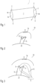
- Fig. 1 shows a preferred embodiment of the implant 1 according to the invention for use in a joint to support a ligament, for example the anterior cruciate ligament of a human knee joint.
- the implant 1 has a coherent support body 2, which in the present exemplary embodiment is essentially tubular or hose-shaped.
- the support body can also have a different geometric shape.
- the support body has an inner, preferably cylindrical, cavity 5, which is enclosed by an outer wall 4. Openings 3a, 3b are provided in the outer wall 4 at opposite ends of the support body. A ligament to be supported or guided can thus be guided through the openings 3a, 3b and through the inner cavity 5.
- the outer wall 4 of the support body 2 is designed to prevent diffusion, preferably in such a way as to greatly restrict or prevent liquid transport from the cavity 5 of the support body to the surroundings of the implant 1. This allows for the formation of a primary healing matrix inside the cavity and in close proximity to the guided ligament.
- the support body 2 can have a net-shaped, foam-like or gel-like structure.
- the support body can, for example, consist of a tightly woven material.
- the cavity 5 is preferably designed with respect to its internal dimensions in such a way that an inner wall 4a of the cavity 5 tightly laterally encloses a ligament to be guided.
- the support body 2 can at least partially consist of elastic material. This ensures optimal adaptation of the support body 2 to the outer contours of the ligament to be guided.
- the implant 1 can optionally have fastening means 6 for fastening and positioning the implant to a bone. These can be formed by eyelets 6 be, which are attached to opposite ends of the support body or integrally formed with the support body.
- the support body 2 preferably consists of a material that can be absorbed by the human body.
- the material of the support body 2 can include, for example, collagen type 1 or 2, polyurethane and/or polyglycolic acid.
- the support body 2 can at least partially have a substance that promotes the growth of a ligament. This can be incorporated into the material of the outer wall of the support body and/or applied to the inner surface 4a of the outer wall, which delimits the cavity 5.
- Fig. 2 is a schematic representation of a human knee joint 20 and shows a proximally torn cruciate ligament 7a, 7b between the femur and tibia bones 10,11.
- the lower torn section 7a of the cruciate ligament is attached to the tibia bone 10.
- the counterpart 7b of the cruciate ligament is attached to the femur 11.
- This counterpart 7b represents a femoral "footprint" of the cruciate ligament, to which the proximally torn section 7a of the cruciate ligament is to be attached.
- the stumps or torn fiber ends 9 of the cruciate ligament piece 7a are first grasped with the help of one or more seams 12 inserted into the knee joint 20.
- the seam or seams 12 are pierced through the fiber ends 9.
- the implant 1 is then applied to the cruciate ligament section 7a using the at least one seam 12. This can be done, for example, by the respective Ends of the seams 12 are formed into a loop 8, over which the implant 1 can be pushed towards the fiber ends 9 by means of the openings 3a, 3b and placed over the cruciate ligament section 7a (see Figs. 4 and 5 ).
- the implant 1 is positioned in such a way that the cruciate ligament section 7a is guided within the cavity 5 of the preferably tubular support body 2.
- the inner wall 4a of the support body preferably rests closely on the circumference of the cruciate ligament section 7a. Splinting of the cruciate ligament section 7a is therefore achieved with the aid of the attached implant 1 as well as alignment or adaptation of the cruciate ligament stumps 9. Due to the weight of the implant 1, it rests on the shin bone 10.
- Grasping the cruciate ligament stumps 9 and sheathing the torn cruciate ligament section 7a is preferably done with the help of an arthroscopic applicator.
- the torn cruciate ligament section 7a is then anatomically repositioned to the femoral “footprint” 7b of the cruciate ligament on the thigh bone 11, as in Fig. 6 shown.
- the torn section 7a or its fiber ends 9 is stretched to the thigh bone 11 with the help of the seam or seams 12 and attached to it.
- This can be done, for example, with the help of a fastening hole 11a provided in the bone 11, which must be drilled into the bone beforehand.
- the seam or seams 12 can be fixed therein using conventional connecting techniques such as knotting the seam ends 13.
- Anchors or bolts are inserted into the bone to fix the suture 12 to it.
- the implant can position itself between the thigh bone 11 and the tibia bone 10, for example due to its own elasticity.
- the openings 3a, 3b of the implant 1 preferably lie on the femur 11 or on the tibia bone 10.
- the inner wall 4a of the implant 1 lies closely against the restored cruciate ligament 7a, 7b, thereby guiding and supporting the cruciate ligament 7a, 7b.
- the diffusion-preventing outer wall 4 of the implant enables the local formation of a primary healing matrix inside the implant and along the restored cruciate ligament 7a, 7b.
- additional growth factors or healing-promoting substances can be introduced into the cavity 5 of the implant 1 by injection, for example using a syringe.
- These can include the following substances: Fresh blood for coagulation in the supporting body 2, blood from the medullary canal with pluripotent stem cells, fibrin, extracellular matrix proteins, vitronectin, stem cells from your own fat, growth factors, cytokines, HGF (Human Growth Factor), Interleukin-1, IL- 3, IL-6, IL-11, PDGF (platelet derived growth factor), FGF (fibroblast growth factor), EGF (epidermal growth factor), VEGF (vascular endothelial growth factor), PRP (platelet rich plasma), PRF (plateler rich fibrin), and/or angiopoietins.
- the substance introduced is held within the cavity 5 by the diffusion-preventing outer wall 4. This is particularly the case with introduced stem cells advantageous because these can promote negative effects such as undesirable cartilage growth if they are transported to another location on the knee joint or the human body.
- the inner wall 4a of the implant can be coated with one or more of the substances mentioned above.
- fixation seams 14 can be provided, which are attached between the implant 1 and one or both of the bones 10, 11.
- the fixing seams 14 can, for example, be attached to optional fasteners 6 of the implant (see Fig. 1 ) can be attached.
- the fixing sutures 14 can be attached to the bones 10, 11 using known methods. For example, drill holes and/or bolts can be provided in the respective bones 10, 11 to fasten the seams 14.
- the openings 3a, 3b preferably lie directly on the femur or tibia bone 10, 11.
- the invention is not limited to the exemplary embodiments shown. It is suitable not only for treating the cruciate ligament, but also for treating other ligaments of the knee joint and other joints, such as the elbow joint or the shoulder joint. It is also suitable not only for the human body but also for the animal body.
Landscapes
- Health & Medical Sciences (AREA)
- Orthopedic Medicine & Surgery (AREA)
- Rehabilitation Therapy (AREA)
- Rheumatology (AREA)
- Cardiology (AREA)
- Oral & Maxillofacial Surgery (AREA)
- Transplantation (AREA)
- Engineering & Computer Science (AREA)
- Biomedical Technology (AREA)
- Heart & Thoracic Surgery (AREA)
- Vascular Medicine (AREA)
- Life Sciences & Earth Sciences (AREA)
- Animal Behavior & Ethology (AREA)
- General Health & Medical Sciences (AREA)
- Public Health (AREA)
- Veterinary Medicine (AREA)
- Prostheses (AREA)
Description
- Die vorliegende Erfindung betrifft ein Implantat für den Einsatz in der Wiederherstellungschirurgie von Gelenken wie beispielsweise dem Kniegelenk bei einem Kreuzbandriss.
- Das menschliche Kniegelenk wird durch ein vorderes und ein hinteres Kreuzband stabilisiert. Bei einem starken Verdrehtrauma kann das Kreuzband entweder teilweise zerstört werden, wobei lediglich einige Fasern reißen, oder es kann zu einer kompletten Ruptur des Kreuzbands kommen. Dabei reißt das vordere Kreuzband 8 bis 10-mal häufiger als das hintere Kreuzband. Die operative Behandlung zur Heilung des Kreuzbands führt nur in weniger als der Hälfte der Behandlungen zu einem akzeptablen Resultat.
- Eine zufriedenstellende Heilung, insbesondere bei einer kompletten Ruptur des vorderen Kreuzbands, ist relativ schwer zu erzielen, da die gerissenen Kreuzbandstümpfe sich anatomisch oft an falscher Stelle befinden und sich eine erforderliche primäre Heilungsmatrix am offenen Kniegelenk nicht bilden kann. Dies führt zu einer anhaltenden Instabilität des Kniegelenks, wodurch Folgeschäden bis hin zur Entwicklung von Arthrose auftreten können. Deshalb wird heutzutage bei einer kompletten Ruptur des vorderen Kreuzbands oft eine Entfernung der Kreuzbandstümpfe vorgenommen und das Kreuzband durch ein Sehnentransplantat ersetzt.
- Die deutsche Offenlegungsschrift
DE 38 03 208 A1 beschreibt beispielweise eine Vorrichtung für die Wiederherstellungschirurgie des Kniegelenks nach einem Kreuzbandriss. Dabei wird das Schienbein relativ zum Oberschenkelknochen stabilisiert, indem die Enden und die Winkellage eines Ersatzbandes im Kniegelenk an Knochenanbringungsplätzen durch eine chirurgische Vorrichtung präzise festgelegt werden. Der Nachteil dieser Vorrichtung und dem damit erzielten Resultat besteht darin, dass das vitale Gewebe des Kreuzbandes entfernt und durch ein avitales Ersatzband ersetzt wird. Dabei verliert das Kniegelenk die propriozeptive Führung, die durch ein vitales Band gewährleistet wird. - Das chinesische Gebrauchsmuster
CN 203 953 876 U beschreibt ein streifenförmiges, hohlrohrartiges und faltbares künstliches Ligament aus gewobenen Material als Ersatz für ein vorderes Kreuzband, aufweisend mehrere unterschiedlich ausgeformte und aufeinanderfolgende Segmente. Durch die streifenförmige und faltbare Form soll die Kontaktfläche des künstlichen Bands mit dem Knochen verbreitert und die Befestigung am Knochen verbessert werden. - Die US Patentschrift
US 5 702 422 A beschreibt ein Verfahren zur Reparatur eines Kreuzbandrisses des menschlichen Knies, wobei das gerissene Band innerhalb einer Spalte zwischen den beiden Konturen des Oberschenkelknochens mittels eines Bolzens und einer damit verbundenen Naht befestigt wird. Dabei soll die Heilung am Ansatz dadurch beschleunigt werden, dass in der Spongiosa des Knochens eine Vertiefung zum Auffangen von Blut ausgebildet ist. Der Nachteil dieses Verfahrens besteht darin, dass die Naht mit dem Bolzen verbunden ist und dadurch ein permanenter Zug auf das gerissene Band ausgeübt wird. Zusätzlich entsteht ein Trauma am Einbringungsort des Bolzens im Oberschenkelknochen. - Die
US 2007/ 0 162 121 A1 beschreibt ein Verfahren und ein Mittel zur Reparatur und Rekonstruktion gerissener Bänder oder Sehnen. Das Mittel umfasst einen biologisch kompatiblen Gewebeklebstoff und eine biologisch abbaubare Faserfolie, ein Netz oder eine andere matrixartige Struktur, die zu einer Schutzhülle verarbeitet ist. Die Schutzhülse weist eine Flexibilität und Kontraktionsfähigkeit auf, die es erlauben, dass sich die Schutzhülse bei Ausdehnung der Schutzhülse in Längsrichtung zusammenzieht und so den Bereich der ausgefransten Ränder, der mit dem Gewebekleber behandelt wurde, komprimiert. Die Schutzhülse ist dabei so ausgelegt, dass sie einer Spannung standhält, die weitgehend der Spannung eines gesunden, funktionierenden Bands oder Sehne bei normaler körperlicher Aktivität entspricht. Die Schutzhülle wird bevor oder nachdem der Klebstoff vollständig auspolymerisiert ist über das behandelte Band gezogen. Alternativ wird, bevor oder nachdem das gerissene Band zusammengeklebt und der Klebstoff vollständig polymerisiert ist, der zusätzliche Gewebeklebstoff, noch in flüssiger Form, zugegeben, um die Schutzhülse zu füllen, und man lässt ihn polymerisieren, um die zusammengeklebten, gerissenen Ränder des Bandes oder der Sehne weiter zu stärken. - Die
US 2009/ 0 157 193 A1 beschreibt ein Verfahren und eine Vorrichtung zur Behandlung oder Heilung einer verletzten Sehne oder eines verletzten Bandes. Die Vorrichtung besteht im Wesentlichen aus einer Folie zur Sehnen- und Bänder-Reparatur. Diese Folie dient dazu, die zu reparierenden Bänder- oder Sehnen zusammenzuhalten, indem es mit Nähten auf der Sehne oder dem Band fixiert ist. Die Sehnen- und Bänderreparaturfolie hat eine poröse Schicht und eine dichtere Schicht und ein therapeutisches Mittel in der porösen Schicht, der dichteren Schicht oder in beiden. Die Reparaturfolie ist aus einem resorbierbaren oder nicht resorbierbaren Polymer hergestellt. - Die
EP 1 493 404 A1 beschreibt ein bioresorbierbares Bindegewebsgerüst zur Reparatur oder den Ersatz von Bändern und Sehnen. Das Bindegewebsgerüst enthält gegenüberliegende Verankerungssegmente die aus bioresorbierbaren Polymerfasern bestehen. Dabei sind die Polymerfasen parallel zu einer Längsachse des Gerüsts ausgerichtet. Weitere Polymerfasern sind quer zu einer Längsachse des Gerüsts ausgerichtet. Das Gerüst wird außerdem mit Gewebsfragmenten oder Zellen beaufschlagt, wodurch ein Nachwachsen und Ersetzten eines Bandes oder einer Sehne ermöglicht wird. - Die
US 2009/ 054 928 A1 beschreibt eine Vorrichtung zum Koppeln eines Weichgewebeimplantats in einem Knochen. Die Vorrichtung umfasst ein Element, um das Weichgewebeimplantat in einen Femurtunnel zu ziehen. Das Element besteht aus einem Nahtmaterial mit einem ersten und einem zweiten Ende, die durch eine erste und eine zweite Öffnung geführt werden, die dem Längskanal zugeordnet sind, um ein Paar von Schlaufen zu bilden. Abschnitte des Nahtmaterials liegen innerhalb der Naht parallel zueinander. Die Anwendung von Spannung auf die Nahtkonstruktion bewirkt die Retraktion des Weichteilimplantats in den Femurtunnel. - Die
US 2007/ 185 532 A1 beschreibt eine Anordnung zur Reparatur von Weichgewebe. Die Anordnung umfasst ein flexibles Element mit einem ersten und einem zweiten Ende und eine Litze, die durch das flexible Element verläuft. Die Litze erstreckt sich durch das flexible Element, so dass das Ziehen an mindestens einem der ersten und zweiten Litzenenden das flexible Element von einer ersten Form, die für das Einführen durch Weichgewebe geeignet ist, in eine zweite Form ändert, die für die sichere Unterbringung der Weichgewebereparaturanordnung relativ zum Weichgewebe geeignet ist. - Die
EP 0 051 954 A2 zeigt eine Ersatzsehne oder ein Ersatzband, mit einer Vielzahl von Längssträngen aus einem biokompatiblen Gewebe. Die Enden der Stränge liegen in einem Gewebe und sind mit einem Film verbunden. Eine Hülse aus einem biokompatiblen Polymer umgibt die künstlichen Stränge, wobei die Stränge zueinander verschiebbar und in der Hülse beweglich sind. Dadurch ist die Last der Struktur gleichmäßig auf die Stränge verteilt. An den Enden der Struktur befinden sich Filme zum Fixieren der Struktur in der implantierten Position. - Die
US 3 613 120 Abeschreibt künstliche Sehnen und insbesondere eine Prothese für Beugesehnen, die gewebte Endabschnitte enthält oder eine andere offene Maschenkonfiguration aufweisen, um das Einwachsen von fibrovaskulärem Gewebe zu fördern. Die künstliche Sehne enthält einen Mittelabschnitt, der aus mehreren parallelen Filamenten besteht, die dem Einwachsen von fibrovaskulärem Gewebe widerstehen und die freie Gleitbewegung des Mittelteils der Prothese fördern. - Der Erfindung liegt die Aufgabe zugrunde, eine Vorrichtung und ein Verfahren bereitzustellen, welche bzw. welches eine verbesserte Heilung bei einem Kreuzbandriss ermöglicht. Diese Aufgabe wird durch die unabhängigen Ansprüche gelöst. Die abhängigen Ansprüche stellen vorteilhafte Weiterbildungen des erfindungsgemäßen Gegenstands dar.
- In einem ersten Aspekt betrifft die Erfindung ein Implantat für den Einsatz in ein Gelenk zur Stützung eines Ligaments, aufweisend einen zusammenhängenden Stützkörper, welcher einen inneren Hohlraum umschließt und welcher zur Führung eines Ligaments des Gelenks ausgebildet ist, und eine erste und zweite Öffnung in einer Außenwand des Stützkörpers, wobei die Außenwand des Stützkörpers diffusionshindernd ausgebildet ist. Die erste und zweite Öffnung sind an sich gegenüberliegenden Enden des Stützkörpers angeordnet und mit dem Hohlraum des Stützkörpers verbunden.
- Das erfindungsgemäße Implantat ermöglicht durch diffusionshindernde Außenwand die Ausbildung oder Bereitstellung einer primären Heilungsmatrix wie beispielsweise einem primären Blutkoagel in unmittelbarer Umgebung des im Hohlraum geführten Ligaments. Hierdurch wird neben einer stabilisierenden Führung bzw. Stützung eines wiederhergestellten bzw. repositionierten Ligaments ein deutlich verbesserter Heilungsverlauf gegenüber den bekannten Wiederherstellungsverfahren ermöglicht.
- Die diffusionshindernde Außenwand des Stützkörpers ist erfindungsgemäß derart ausgebildet, dass ein Flüssigkeitstransport vom Hohlraum des Stützkörpers hin zur Umgebung verhindert wird. Hierbei wird Flüssigkeit an einem Verlassen des Hohlraums durch die Außenwand gehindert. Die diffusionshindernde Außenwand kann beispielsweise durch eine im Wesentlichen geschlossene Oberfläche gebildet sein. Die Oberfläche kann jedoch auch Poren oder Mikroporen aufweisen.
- Das Implantat ist vorzugsweise derart ausgebildet, um eine seitliche Führung des Ligaments zu ermöglichen. Hierdurch werden eine einfachere Adaptation der gerissenen Ligamentfasern und eine seitliche Stabilisierung des wiederhergestellten bzw. repositionierten Ligaments erzielt.
- Der Hohlraum des Stützkörpers ist erfindungsgemäß derart dimensioniert, dass die Ausbildung einer primären Heilungsmatrix, wie beispielsweise einem primären Blutkoagel, um ein im Hohlraum geführtes Ligament ermöglicht wird. Ein Innendurchmesser des Hohlraums ist hierbei an die seitliche Erstreckung des Kreuzbandes angepasst und eine Innenwand des Hohlraums umschließt das zu führende Ligament am Umfang enganliegend.
- In den inneren Hohlraum des Stützkörpers sind erfindungsgemäß ein oder mehrere Wachstumsfaktoren und/oder die Heilung fördernde Substanzen durch ein Injektionsmittel injizierbar.
- Der Stützkörper besteht vorzugsweise wenigstens teilweise aus elastischem Material. Der Stützkörper kann vorzugsweise in Längsrichtung und/oder lateraler Richtung elastisch gestreckt bzw. gedehnt werden. Hierdurch kann sich der Stützkörper an den Umfang bzw. die Form und Länge des zu stützenden Ligaments individuell anpassen. Des Weiteren ist die Ausbildung einer primären Heilungsmatrix in unmittelbarer Nähe zum Ligament durch das elastische Material möglich, ohne dass die Gefahr eines Aufreißens des Stützkörpers besteht.
- Der Stützkörper ist vorzugsweise im Wesentlichen schlauchförmig oder ballonförmig ausgeprägt. Die seitliche Erstreckung bzw. die Breite des Stützkörpers kann dabei homogen entlang der länglichen Erstreckungsrichtung des Stützkörpers sein. Der Stützkörper kann jedoch auch andere geometrische Formen aufweisen, welche ein Stützung bzw. Führung des Ligaments vorzugsweise in Längsrichtung des Ligaments ermöglichen.
- Der Stützkörper kann eine netzförmige, schaumartige oder gelartige Struktur aufweisen. Beispielsweise kann der Stützkörper aus einem engmaschig gewobenen Material bestehen. Die Poren des Materials können hierbei als Diffusionsbarriere ausgeprägt sein.
- Der Stützkörper besteht vorzugsweise aus einem vom menschlichen Körper resorbierbarem Material. Der Stützkörper kann jedoch auch aus einem nicht resorbierbaren Material bestehen. Das Material des Stützkörpers kann eines oder mehrere der folgenden Materialien umfassen: Collagen Typ 1 oder 2, Polyurethan und/oder Polyclycolsäure. Der Stützkörper ist vorzugsweise vollständig aus einem der oben genannten Materialien geformt. Insbesondere die Außenwand ist vorzugsweise integral mit dem Stützkörper ausgebildet.
- In einem bevorzugten Ausführungsbeispiel weist das Implantat wenigstens teilweise eine für ein Ligament wachstumsfördernde Substanz auf. Diese kann beispielsweise auf der Außenwand angeordnet oder in diese eingebracht sein. Vorzugsweise ist eine Innenfläche der Außenwand des Stützkörpers mit der wachstumsfördernden Substanz wenigstens teilweise beschichtet.
- Die wachstumsfördernde Substanz kann eine oder mehrere der folgenden Substanzen umfassen: pluripotente Stammzellen, Fibrin, extrazelluläre Matrixproteine, Vitronektin, Stammzellen aus Eigenfett, Wachstumskatore, Zytokine, HGF (Human Growth Factor), Interleukin-1, IL-3, IL-6, IL-11, PDGF (platelet derived growth factor), FGF (fibroblast growth factor), EGF (epidermal growth factor), VEGF (vascular endothelial growth factor), PRP (platelet rich plasma), PRF (plateler rich fibrin) und/oder Angiopoetine.
- Das Implantat kann an den beiden gegenüberliegenden Enden Befestigungsmittel zur Befestigung und Positionierung an einen Knochen aufweisen. Diese können integral mit dem Stützkörper ausgebildet sein. Die Befestigungsmittel können beispielsweise Ösen umfassen, an welche eine Verbindungsnaht zwischen Implantat und einem Knochen befestigt werden kann. Hierdurch kann das Implantat bezüglich eines Knochens und dem im Implantat geführten Ligament fix positioniert werden. Die hierfür verwendete Naht kann aus einem vom menschlichen Körper resorbierbarem Material bestehen, beispielsweise PDS (Polydioxanon) oder PGS (PolyGlycolsäure). In einem bevorzugten Ausführungsbeispiel können auch eine oder mehrere derartige Befestigungsnähte integral mit dem Implantat geformt sein.
- Das Implantat ist vorzugsweise für den Einsatz in einem menschlichen Kniegelenk vorgesehen. Dabei ist das Implantat derart ausgebildet, um eine Führung eines Ligaments des Kniegelenks, insbesondere des vorderen Kreuzbandes zu ermöglichen. Das Implantat kann auch zur Führung von anderen Ligamenten des menschlichen oder tierischen Körpers verwendet werden.
- In einem nicht zur Erfindung gehörenden Beispiel wird ein Verfahren zur Wiederherstellung eines gerissenen Bandes, insbesondere Kreuzbandes, in einem menschlichen oder tierischen Gelenk, insbesondere Kniegelenk, mit Hilfe eines Implantats beschrieben, aufweisend die Schritte:
- Fassen der Stümpfe eines gerissenen Teils des Bandes mittels einer Naht,
- Ummantelung des gerissenen Teils des Bandes mit einem Implantat aufweisend einen Hohlraum umschließenden Stützkörper, so dass der gerissenen Teil des Bandes in dem Hohlraum des Stützkörpers geführt wird, wobei eine Außenwand des Stützkörpers wenigstens teilweise diffusionshindernd ausgebildet ist,
- anatomische Reposition des gerissenen Teils des Bandes an einen Knochen des Gelenks und/oder an das entsprechende Gegenstück des gerissenen Bandes,
- Fixation des Implantats an einen Knochen des Gelenks, wie beispielsweise dem Oberschenkel und/oder Schienbeinknochen.
- Durch das nicht zur Erfindung gehörende Verfahren wird eine einfache und effiziente Wiederherstellung des gerissenen Bandes, insbesondere Kreuzbandes, ermöglicht, wobei die Ummantelung des Bandes mit Hilfe eines hohlraumaufweisenden und diffusionshindernden Implantats eine verbesserte Heilung des repositionierten Kreuzbandes ermöglicht. Hierbei wird insbesondere die Bildung einer primären Heilungsmatrix vereinfacht bzw. ermöglicht, welche sich entlang des repositionierten Kreuzbandes innerhalb des Hohlraums des Implantats ausbilden kann. Obwohl sich das Verfahren auch für andere Bänder eignet, wird es im Folgenden anhand des Kreuzbandes erläutert.
- Bei der Ausrichtung und/oder Adaptation der gerissenen Stümpfe des Kreuzbandes werden diese zunächst mit einer Naht gefasst. Hierbei können eine, zwei oder mehrere Nähte durch die Stümpfe des Kreuzbandes geführt werden. Danach erfolgt die Ummantelung der Kreuzbandstümpfe mit Hilfe des Implantats. Dieses kann beispielsweise durch die zuvor bereitgestellten Nähte hin zu den Kreuzbandstümpfen geführt und auf diese geschoben bzw. über diese gestülpt werden. Hierdurch erfolgt eine Adaptation der aufgefaserten Kreuzbandstümpfe. Des Weiteren wird ein die Kreuzbandstümpfe umgebener Hohlraum im Inneren des Stützkörpers generiert, in welchem sich eine primäre Heilungsmatrix wie beispielsweise ein primäres Blutkoagel bilden kann. Ein Innendurchmesser des Implantathohlraums ist hierbei vorzugsweise an den Außendurchmesser bzw. die seitliche Erstreckung des Kreuzbandes angepasst. Zusätzlich erfolgt durch die Aufbringung des Implantats auf die Kreuzbandstümpfe eine seitliche Schienung des gerissenen Kreuzbands.
- Das Fassen der Kreuzbandstümpfe, die Adaptation der Stümpfe und die Ummantelung des gerissenen Teils des Kreuzbands erfolgt vorzugsweise mit Hilfe eines arthroskopischen Applikators.
- Das Verfahren kann ferner eine Injektion von zusätzlichen Wachstumsfaktoren oder heilungsfördernden Substanzen in den Hohlraum des Stützkörpers umfassen. Dies kann mit Hilfe eines geeigneten Injektionsmittels erfolgen, mit welchem beispielsweise die Außenwand des Implantats wenigstens an einer Stelle zur Injektion perforiert werden kann.
- Die Wachstumsfaktoren oder heilungsfördernden Substanzen können eine oder mehrere der folgenden Substanzen umfassen: Frischblut zur Gerinnung im Stützkörper, Blut aus dem Markraum mit pluripotenten Stammzellen, Fibrin, extrazelluläre Matrixproteine, Vitronektin, Stammzellen aus Eigenfett, Wachstumskatore, Zytokine, HGF (Human Growth Factor), Interleukin-1, IL-3, IL-6, IL-11, PDGF (platelet derived growth factor), FGF (fibroblast growth factor), EGF (epidermal growth factor), VEGF (vascular endothelial growth factor), PRP (platelet rich plasma), PRF (plateler rich fibrin), und/oder Angiopoetine.
- Das Verfahren weist vorzugsweise einen Schritt zur intraartikulären Stabilisation des Implantats auf. Dies kann beispielsweise durch eine Zusatznaht, autoelastische Spannung und/oder durch zusätzliche Fixation des Implantats an einen Knochen erfolgen. Hierbei können zur Befestigung des Implantats entweder zusätzliche Nähte am Implantat, zwischen Implantat und Kreuzband oder zwischen Implantat und Knochen angebracht werden. Die jeweilige Naht kann an entsprechend vorgeformten Befestigungsmitteln wie beispielsweise Ösen am Implantat befestigt werden. Knochenseitig kann die Befestigungsnaht beispielweise an eingebrachten Bolzen befestigt werden. Das Implantat kann sich zusätzlich oder alternativ durch dessen Eigenelastizität stabilisieren.
- Vorzugsweise weist das Verfahren weiterhin den Schritt einer intra- oder extraartikulären Stabilisation des Kniegelenks auf. Eine derartige Stabilisation kann beispielsweise mittels einer extraartikulären Schiene erfolgen. Alternativ oder zusätzlich kann eine dynamische intraligamentäre Stabilisation (Ligamys ™) und/oder eine intraartikuläre Punkt-zu-Punkt-Verbindung (Internal Brace™) zur Stabilisation verwendet werden.
- Das Implantat und die beim Verfahren verwendeten Nähte sind vorzugsweise aus einem vom menschlichen oder tierischen Körper resorbierbarem Material hergestellt. Das Implantat muss somit nicht sekundär durch eine zusätzliche Operation entfernt werden. Das Implantat ist vorzugsweise aus Collagen Typ 1 oder 2, Polyurethan und/oder Polyclycolsäure geformt. Die Naht bzw. die beim Verfahren verwendeten Nähte sind vorzugsweise aus PDS (Polydioxanon) und/oder PGS (PolyGlycolsäure) geformt.
- Das gesamte Verfahren kann arthroskopisch durchgeführt werden, das heisst ohne zusätzliche Inzisionen im Vergleich zur herkömmlichen Arthroskopie anzubringen.
- Das für das Verfahren verwendete Implantat kann einen im Wesentlichen rohr- oder ballonförmigen Stützkörper aufweisen. Das Implantat kann eine netzförmige Struktur, eine schaumartige oder gelartige Struktur aufweisen. Das Implantat kann vorzugsweise wenigstens teilweise elastisch ausgeprägt sein. Das für das Verfahren verwendete Implantat kann des Weiteren wie oben in Bezug auf die Erfindung beschrieben ausgebildet sein.
- Nachfolgend wird ein Ausführungsbeispiel der Erfindung lediglich beispielhaft beschrieben und eine detaillierte Beschreibung der Figuren der Zeichnung gegeben.
- Fig. 1
- ist eine schematische Zeichnung eines bevorzugten Ausführungsbeispiels des erfindungsgemäßen Implantats;
- Fig. 2
- ist eine schematische Zeichnung eines menschlichen Kniegelenks mit einem proximal gerissenen Kreuzband zwischen Oberschenkel- und Schienbeinknochen;
- Fig. 3
- ist eine schematische Ansicht des Kniegelenks gemäß
Fig. 2 und zeigt das Fassen der ausgefransten Kreuzbandstümpfe mittels einer Naht; - Fig. 4
- ist eine schematische Ansicht des Kniegelenks und zeigt das Einbringen eines bevorzugten Ausführungsbeispiels des erfindungsgemäßen Implantats auf das proximal gerissene Kreuzband;
- Fig. 5
- ist eine schematische Ansicht des Kniegelenks und zeigt das Überstülpen eines bevorzugten Ausführungsbeispiels des erfindungsgemäßen Implantats auf das proximal gerissene Kreuzband;
- Fig. 6
- ist eine schematische Ansicht des Kniegelenks und zeigt die anatomische Reposition des proximal gerissenen Kreuzbandes an die Abrissstelle des Oberschenkelknochens und
- Fig. 7
- ist eine schematische Ansicht des Kniegelenks und zeigt die Fixation des Implantats und die Injektion von heilungsfördernden Substanzen.
-
Fig. 1 zeigt ein bevorzugtes Ausführungsbeispiel des erfindungsgemäßen Implantats 1 für den Einsatz in ein Gelenk zur Stützung eines Ligaments, beispielsweise dem vorderen Kreuzband eines menschlichen Kniegelenks. - Das Implantat 1 weist einen zusammenhängenden Stützkörper 2 auf, welcher im vorliegenden Ausführungsbeispiel im Wesentlichen rohr- bzw. schlauchförmig ausgebildet ist. Der Stützkörper kann jedoch auch eine andere geometrische Form aufweisen.
- Der Stützkörper weist einen inneren vorzugsweise zylinderförmigen Hohlraum 5 auf, welcher von einer Außenwand 4 umschlossen ist. An gegenüberliegenden Enden des Stützkörpers sind Öffnungen 3a,3b in der Außenwand 4 vorgesehen. Ein zu stützendes oder zu führendes Ligament kann somit durch die Öffnungen 3a,3b und durch den inneren Hohlraum 5 geführt werden.
- Die Außenwand 4 des Stützkörpers 2 ist diffusionshindernd ausgebildet, vorzugsweise derart, um einen Flüssigkeitstransport vom Hohlraum 5 des Stützkörpers hin zur Umgebung des Implantats 1 stark einzuschränken oder zu verhindern. Hierdurch wird die Bildung einer primären Heilungsmatrix im Inneren des Hohlraums und in unmittelbarer Nähe zum geführten Ligament ermöglicht.
- Der Stützkörper 2 kann eine netzförmige, schaumartige oder gelartige Struktur aufweisen. Der Stützkörper kann beispielsweise aus einem engmaschig gewobenen Material bestehen.
- Der Hohlraum 5 ist vorzugsweise bezüglich dessen innerer Abmessungen derart ausgeprägt, dass eine Innenwand 4a des Hohlraums 5 ein zu führendes Ligament seitlich eng umschließt. Der Stützkörper 2 kann wenigstens teilweise aus elastischem Material bestehen. Dies gewährleistet eine optimale Anpassung des Stützkörpers 2 an die Außenkonturen des zu führenden Ligaments.
- Das Implantat 1 kann optional Befestigungsmittel 6 zur Befestigung und Positionierung des Implantats an einen Knochen aufweisen. Diese können durch Ösen 6 gebildet sein, welche an gegenüberliegenden Enden des Stützkörpers angebracht oder integral mit dem Stützkörper geformt sind.
- Der Stützkörper 2 besteht vorzugsweise aus einem vom menschlichen Körper resorbierbaren Material. Das Material des Stützkörpers 2 kann beispielsweise Collagen Typ 1 oder 2, Polyurethan und/oder Polyclycolsäure umfassen.
- Der Stützkörper 2 kann wenigstens teilweise eine für ein Ligament wachstumsfördernde Substanz aufweisen. Diese kann in das Material der Außenwand des Stützkörpers eingebracht sein und/oder auf die Innenfläche 4a der Außenwand aufgebracht sein, welche den Hohlraum 5 begrenzt.
- Das nicht zur Erfindung gehörende Verfahren wird im Folgenden in Bezug auf die
Fig. 2 bis 7 beschrieben. -
Fig. 2 ist eine schematische Darstellung eines menschlichen Kniegelenks 20 und zeigt ein proximal gerissenes Kreuzband 7a,7b zwischen Oberschenkel- und Schienbeinknochen 10,11. Das untere gerissene Teilstück 7a des Kreuzbandes ist am Schienbeinknochen 10 befestigt. Das Gegenstück 7b des Kreuzbandes ist am Oberschenkelknochen 11 angebracht. Dieses Gegenstück 7b stellt einen femoralen "Footprint" des Kreuzbandes dar, an welchem das proximal gerissene Teilstück 7a des Kreuzbandes zu befestigen ist. - Wie in
Fig. 3 gezeigt, werden hierbei zunächst die Stümpfe bzw. gerissenen Faserenden 9 des Kreuzbandstücks 7a mit Hilfe einer oder mehrerer ins Kniegelenk 20 eingebrachten Nähte 12 gefasst. Die Naht bzw. die Nähte 12 werden hierbei durch die Faserenden 9 gestochen. - Danach wird das Implantat 1 mit Hilfe der wenigstens einen Naht 12 auf das Kreuzbandteilstück 7a aufgebracht. Dies kann beispielsweise dadurch erfolgen, dass die jeweiligen Enden der Nähte 12 zu einer Schlaufe 8 geformt werden, über welche das Implantat 1 mittels der Öffnungen 3a,3b hin zur den Faserenden 9 geschoben und über das Kreuzbandteilstück 7a gestülpt werden kann (siehe
Fig. 4 und 5 ). - Das Implantat 1 wird hierbei derart positioniert, dass das Kreuzbandteilstück 7a innerhalb des Hohlraums 5 des vorzugsweise schlauchförmigen Stützköpers 2 geführt wird. Die Innenwand 4a des Stützkörpers liegt hierbei vorzugsweise eng am Umfang des Kreuzbandteilstücks 7a an. Es wird demnach eine Schienung des Kreuzbandteilstücks 7a mit Hilfe des aufgesetzten Implantats 1 als auch eine Ausrichtung bzw. Adaptation der Kreuzbandstümpfe 9 erzielt. Durch das Eigengewicht des Implantats 1 liegt dieses auf dem Schienbeinknochen 10 auf.
- Das Fassen der Kreuzbandstümpfe 9 und die Ummantelung des gerissenen Kreuzbandteilstücks 7a erfolgt vorzugsweise mit Hilfe eines arthroskopischen Applikators.
- Anschließend erfolgt die anatomische Reposition des gerissenen Kreuzbandteilstücks 7a an den femoralen "Footprint" 7b des Kreuzbandes am Oberschenkelknochen 11, wie in
Fig. 6 gezeigt. Hierbei wird das gerissene Teilstück 7a bzw. dessen Faserenden 9 mit Hilfe der Naht bzw. Nähte 12 zum Oberschenkelknochen 11 gedehnt und an diesem befestigt. Dies kann beispielsweise mit Hilfe eines im Knochen 11 vorgesehenen Befestigungslochs 11a erfolgen, welches zuvor in den Knochen zu bohren ist. Darin kann die Naht bzw. die Nähte 12 mit Hilfe von konventionellen Verbindungstechniken wie beispielsweise Knüpfen der Nahtenden 13 fixiert werden. Alternativ oder zusätzlich zum Vorsehen eines Bohrlochs 11a im Knochen 11 kann ein Anker bzw. Bolzen (nicht gezeigt) in den Knochen eingebracht werden, um die Naht 12 daran zu fixieren. - Nach der Reposition des gerissenen Kreuzbands 7a,7b kann sich das Implantat zwischen Oberschenkelknochen 11 und Schienbeinknochen 10 beispielsweise durch dessen Eigenelastizität selbst positionieren. Hierbei liegen vorzugsweise die Öffnungen 3a,3b des Implantats 1 am Oberschenkelknochen 11 bzw. am Schienbeinknochen 10 an. Die Innenwand 4a des Implantats 1 liegt eng am wiederhergestellten Kreuzband 7a,7b an, wodurch eine Führung und Stützung des Kreuzbandes 7a,7b erzielt wird. Durch die diffusionshindernde Außenwand 4 des Implantats wird die lokale Ausbildung einer primären Heilungsmatrix im Inneren des Implantats und entlang des wiederhergestellten Kreuzbands 7a,7b ermöglicht.
- Optional können durch Injektion beispielsweise mittels einer Spritze 15 zusätzliche Wachstumsfaktoren oder heilungsfördernden Substanzen in den Hohlraum 5 des Implantats 1 eingebracht werden. Diese können die folgenden Substanzen umfassen: Frischblut zur Gerinnung im Stützkörper 2, Blut aus dem Markraum mit pluripotenten Stammzellen, Fibrin, extrazelluläre Matrixproteine, Vitronektin, Stammzellen aus Eigenfett, Wachstumskatore, Zytokine, HGF (Human Growth Factor), Interleukin-1, IL-3, IL-6, IL-11, PDGF (platelet derived growth factor), FGF (fibroblast growth factor), EGF (epidermal growth factor), VEGF (vascular endothelial growth factor), PRP (platelet rich plasma), PRF (plateler rich fibrin), und/oder Angiopoetine.
- Durch die diffusionshindernde Außenwand 4 wird die eingebrachte Substanz innerhalb des Hohlraums 5 gehalten. Dies ist insbesondere bei eingebrachten Stammzellen vorteilhaft, da diese negative Auswirkungen wie beispielsweise ungewünschten Knorpelwachstum begünstigen können, wenn diese an eine andere Stelle des Kniegelenks oder des menschlichen Körpers transportiert werden. Alternativ zu der beschriebenen Einbringung von Wachstumsfaktoren oder heilungsfördernden Substanzen in das Implantat 1 kann die Innenwand 4a des Implantats mit einer oder mehreren der oben genannten Substanzen beschichtet sein.
- Zur weiteren Stabilisierung des Implantats 1 im Kniegelenk können zusätzliche Fixiernähte 14 vorgesehen werden, welche zwischen Implantat 1 und einem oder beiden der Knochen 10,11 angebracht werden. Die Fixiernähte 14 können beispielsweise an optionalen Befestigungsmitteln 6 des Implantats (siehe
Fig. 1 ) befestigt werden. An den Knochen 10, 11 können die Fixiernähte 14 mit bekannten Verfahren befestigt werden. Beispielsweise können Bohrlöcher und/oder Bolzen in den jeweiligen Knochen 10,11 zur Befestigung der Nähte 14 vorgesehen werden. Im fixierten Zustand des Implantats 1 wie inFig. 7 gezeigt liegen die Öffnungen 3a,3b vorzugsweise direkt am Oberschenkel- bzw. Schienbeinknochen 10,11 an. - Die Erfindung ist nicht auf die dargestellten Ausführungsbeispiele beschränkt. Sie eignet sich nicht nur zur Behandlung des Kreuzbandes, sondern auch zur Behandlung anderer Bänder des Kniegelenks und anderer Gelenke, wie beispielsweise des Ellbogengelenks oder des Schultergelenks. Es eignet sich auch nicht nur für den menschlichen Körper sondern auch für den tierischen Körper.
Claims (11)
- Implantat (1) für den Einsatz in ein Gelenk (20) zur Stützung eines Ligaments (7a,7b), aufweisendeinen zusammenhängenden Stützkörper (2), welcher einen inneren Hohlraum (5) umschließt und welcher zur Führung eines Ligaments (7a,7b) des Gelenks (20) ausgebildet ist, undeine erste und zweite Öffnung (3a,3b) in einer Außenwand (4) des Stützkörpers,wobei die Außenwand (4) des Stützkörpers (2) diffusionshindernd ausgebildet ist, so dass ein Flüssigkeitstransport vom inneren Hohlraum (5) hin zur Umgebung des Implantats (1) verhindert ist,dadurch gekennzeichnet,dass der Innendurchmesser des Hohlraums (5) des Stützkörpers (2) an die seitliche Erstreckung des Ligaments (7a, 7b) angepasst ist und eine Innenwand (4a) des Hohlraums (5) ein zu führendes Ligament (7a,7b) am Umfang enganliegend umschließt, so dass die Ausbildung einer primären Heilungsmatrix um das im Hohlraum geführte Ligament (7a,7b) ermöglicht ist, unddass in den inneren Hohlraum (5) ein oder mehrere Wachstumsfaktoren und/oder die Heilung fördernde Substanzen durch ein Injektionsmittel (15) injizierbar sind, unddass die erste und zweite Öffnung (3a,3b) an sich gegenüberliegenden Enden des Stützkörpers (2) angeordnet und mit dem Hohlraum (5) des Stützkörpers verbunden sind.
- Das Implantat gemäß Anspruch 1,
wobei der Stützkörper (2) wenigstens teilweise aus elastischem Material besteht. - Das Implantat gemäß Anspruch 1 oder 2,
wobei der Stützkörper (2) im Wesentlichen schlauchförmig oder ballonförmig ist. - Das Implantat gemäß einem der Ansprüche 1 bis 3,
wobei der Stützkörper (2) eine netzförmige, schaumartige oder gelartige Struktur aufweist. - Das Implantat gemäß einem der vorhergehenden Ansprüche,
wobei der Stützkörper (2) aus einem engmaschig gewobenen Material besteht. - Das Implantat gemäß einem der vorherigen Ansprüche,
wobei der Stützkörper (2) aus einem vom menschlichen oder tierischen Körper resorbierbarem Material besteht. - Das Implantat gemäß einem der vorherigen Ansprüche,
wobei das Material des Stützkörpers (2) eines oder mehrere der folgenden Materialien umfasst: Collagen Typ 1 oder 2, Polyurethan, Polyclycolsäure. - Das Implantat gemäß einem der vorherigen Ansprüche,
wobei der Stützkörper (2) wenigstens teilweise eine für ein Ligament (7a,7b) wachstumsfördernde Substanz aufweist. - Das Implantat gemäß Anspruch 8,
wobei eine Innenfläche (4a) der Außenwand (4) des Stützkörpers (2) mit der wachstumsfördernden Substanz wenigstens teilweise beschichtet ist. - Das Implantat gemäß Anspruch 8 oder 9,
wobei die wachstumsfördernde Substanz eine oder mehrere der folgenden Substanzen umfasst: pluripotente Stammzellen, Fibrin, extrazelluläre Matrixproteine, Vitronektin, Stammzellen aus Eigenfett, Wachstumskatore, Zytokine, HGF (Human Growth Factor), Interleukin-1, IL-3, IL-6, IL-11, PDGF (platelet derived growth factor), FGF (fibroblast growth factor), EGF (epidermal growth factor), VEGF (vascular endothelial growth factor), PRP (platelet rich plasma), PRF (plateler rich fibrin) und/oder Angiopoetine. - Das Implantat gemäß einem der vorherigen Ansprüche,
wobei der Stützkörper (2) an den beiden gegenüberliegenden Enden Befestigungsmittel (6) zur Befestigung und Positionierung an einen Knochen (10,11) aufweist.
Applications Claiming Priority (2)
| Application Number | Priority Date | Filing Date | Title |
|---|---|---|---|
| DE102015225218.3A DE102015225218B4 (de) | 2015-12-15 | 2015-12-15 | Implantat für den Einsatz in ein Gelenk zur Stützung eines Ligaments |
| PCT/EP2016/077150 WO2017102184A1 (de) | 2015-12-15 | 2016-11-09 | Banderhaltendes implantat |
Publications (3)
| Publication Number | Publication Date |
|---|---|
| EP3389558A1 EP3389558A1 (de) | 2018-10-24 |
| EP3389558C0 EP3389558C0 (de) | 2024-03-06 |
| EP3389558B1 true EP3389558B1 (de) | 2024-03-06 |
Family
ID=57389386
Family Applications (1)
| Application Number | Title | Priority Date | Filing Date |
|---|---|---|---|
| EP16798659.5A Active EP3389558B1 (de) | 2015-12-15 | 2016-11-09 | Banderhaltendes implantat |
Country Status (3)
| Country | Link |
|---|---|
| EP (1) | EP3389558B1 (de) |
| DE (1) | DE102015225218B4 (de) |
| WO (1) | WO2017102184A1 (de) |
Citations (1)
| Publication number | Priority date | Publication date | Assignee | Title |
|---|---|---|---|---|
| US3613120A (en) * | 1969-10-21 | 1971-10-19 | Research Corp | Flexor tendon prosthesis |
Family Cites Families (11)
| Publication number | Priority date | Publication date | Assignee | Title |
|---|---|---|---|---|
| US4455690A (en) * | 1980-11-06 | 1984-06-26 | Homsy Charles A | Structure for in vivo implanation |
| US4739751A (en) | 1986-10-03 | 1988-04-26 | Temple University | Apparatus and method for reconstructive surgery |
| US5702422A (en) | 1995-12-06 | 1997-12-30 | Stone; Kevin R. | Anterior cruciate ligament repair method |
| US8226715B2 (en) * | 2003-06-30 | 2012-07-24 | Depuy Mitek, Inc. | Scaffold for connective tissue repair |
| US8137382B2 (en) * | 2004-11-05 | 2012-03-20 | Biomet Sports Medicine, Llc | Method and apparatus for coupling anatomical features |
| US7749250B2 (en) * | 2006-02-03 | 2010-07-06 | Biomet Sports Medicine, Llc | Soft tissue repair assembly and associated method |
| AU2007204815A1 (en) * | 2006-01-12 | 2007-07-19 | Histogenics Corporation | Method for repair and reconstruction of ruptured ligaments or tendons and for treatment of ligament and tendon injuries |
| US8585753B2 (en) * | 2006-03-04 | 2013-11-19 | John James Scanlon | Fibrillated biodegradable prosthesis |
| US20090157193A1 (en) | 2007-12-18 | 2009-06-18 | Warsaw Orthopedic, Inc. | Tendon and Ligament Repair Sheet and Methods of Use |
| WO2013040325A1 (en) * | 2011-09-15 | 2013-03-21 | Arsenal Medical, Inc. | Implants for post-operative pain |
| CN203953876U (zh) | 2014-03-07 | 2014-11-26 | 复旦大学附属华山医院 | 中空管带状可折叠悬吊式人工韧带 |
-
2015
- 2015-12-15 DE DE102015225218.3A patent/DE102015225218B4/de active Active
-
2016
- 2016-11-09 EP EP16798659.5A patent/EP3389558B1/de active Active
- 2016-11-09 WO PCT/EP2016/077150 patent/WO2017102184A1/de not_active Ceased
Patent Citations (1)
| Publication number | Priority date | Publication date | Assignee | Title |
|---|---|---|---|---|
| US3613120A (en) * | 1969-10-21 | 1971-10-19 | Research Corp | Flexor tendon prosthesis |
Also Published As
| Publication number | Publication date |
|---|---|
| WO2017102184A1 (de) | 2017-06-22 |
| EP3389558C0 (de) | 2024-03-06 |
| DE102015225218A1 (de) | 2017-06-22 |
| DE102015225218B4 (de) | 2023-03-09 |
| EP3389558A1 (de) | 2018-10-24 |
Similar Documents
| Publication | Publication Date | Title |
|---|---|---|
| DE60132135T2 (de) | Verwendung einer Klebesubstanz zur Herstellung eines Knochenklebestoffes zur Befestigung eines Knochenstopfens in einem Knochenkanal | |
| EP1334702B1 (de) | Ankerelement zum Verankern eines Ligamenttransplantates | |
| DE69832800T2 (de) | Chirugische hilfe zur gewebetransplantation | |
| DE60022590T2 (de) | Befestigungsvorrichtung und -verfahren für ein Transplantat | |
| DE60122885T2 (de) | Fixierungsanker | |
| DE69209262T2 (de) | Vorrichtung zum verstärken eines ligamenttransplantats in der wiederherstellungschirurgie | |
| DE69826688T2 (de) | Vorrichtung zum verankern von körpereigenen oder künstlichen sehnentransplantaten in knochen | |
| DE69433138T2 (de) | Fadenverankerungsvorrichtung | |
| DE102008016607B4 (de) | Vorrichtung zur Implantation in einen Knochen und ein System für eine Beanspruchung eines rekonstruierten vorderen Kreuzbands während der Heilungsphase aufweisend die Vorrichtung | |
| DE102009051367B4 (de) | Implantierbares System mit kontinuierlichem Auflösungsmechanismus bei der Ausheilung | |
| DE69734606T2 (de) | Vorrichtung zur befestigung von körpereigenen oder künstlichen sehnentransplantaten in knochen | |
| DE69617423T2 (de) | Gelenkprothese | |
| DE60013768T2 (de) | Weichgewebsbefestigung | |
| DE69232266T2 (de) | Transplantat zur unterstützung von autogenem gewebewachstum | |
| EP2086437B1 (de) | Implantat für Röhrenknochen | |
| EP3389558B1 (de) | Banderhaltendes implantat | |
| US20230380955A1 (en) | Combination therapy for tissue repair | |
| CN209916298U (zh) | 一种用于韧带或肌腱的固定装置 | |
| JP7034983B2 (ja) | コラーゲン構築物、およびコラーゲン構築物を生成する方法 | |
| US20250025288A1 (en) | Graft and scaffold acl repair system | |
| US20250366843A1 (en) | Bioinductive collagen anchor for tissue repair | |
| RU2340301C2 (ru) | Способ пластики ахиллова сухожилия | |
| RU2750464C1 (ru) | Артроскопическое протезирование передней крестовидной связки у собак | |
| DE102023130257A1 (de) | Endo-Exo-Prothese für Gliedmaßen | |
| DE102004032115B4 (de) | Implantat zur Erhöhung der Ausrissfestigkeit von Sehnennähten |
Legal Events
| Date | Code | Title | Description |
|---|---|---|---|
| STAA | Information on the status of an ep patent application or granted ep patent |
Free format text: STATUS: UNKNOWN |
|
| STAA | Information on the status of an ep patent application or granted ep patent |
Free format text: STATUS: THE INTERNATIONAL PUBLICATION HAS BEEN MADE |
|
| PUAI | Public reference made under article 153(3) epc to a published international application that has entered the european phase |
Free format text: ORIGINAL CODE: 0009012 |
|
| STAA | Information on the status of an ep patent application or granted ep patent |
Free format text: STATUS: REQUEST FOR EXAMINATION WAS MADE |
|
| 17P | Request for examination filed |
Effective date: 20180605 |
|
| AK | Designated contracting states |
Kind code of ref document: A1 Designated state(s): AL AT BE BG CH CY CZ DE DK EE ES FI FR GB GR HR HU IE IS IT LI LT LU LV MC MK MT NL NO PL PT RO RS SE SI SK SM TR |
|
| AX | Request for extension of the european patent |
Extension state: BA ME |
|
| DAV | Request for validation of the european patent (deleted) | ||
| DAX | Request for extension of the european patent (deleted) | ||
| STAA | Information on the status of an ep patent application or granted ep patent |
Free format text: STATUS: EXAMINATION IS IN PROGRESS |
|
| 17Q | First examination report despatched |
Effective date: 20210205 |
|
| GRAP | Despatch of communication of intention to grant a patent |
Free format text: ORIGINAL CODE: EPIDOSNIGR1 |
|
| STAA | Information on the status of an ep patent application or granted ep patent |
Free format text: STATUS: GRANT OF PATENT IS INTENDED |
|
| INTG | Intention to grant announced |
Effective date: 20231018 |
|
| GRAS | Grant fee paid |
Free format text: ORIGINAL CODE: EPIDOSNIGR3 |
|
| GRAA | (expected) grant |
Free format text: ORIGINAL CODE: 0009210 |
|
| STAA | Information on the status of an ep patent application or granted ep patent |
Free format text: STATUS: THE PATENT HAS BEEN GRANTED |
|
| AK | Designated contracting states |
Kind code of ref document: B1 Designated state(s): AL AT BE BG CH CY CZ DE DK EE ES FI FR GB GR HR HU IE IS IT LI LT LU LV MC MK MT NL NO PL PT RO RS SE SI SK SM TR |
|
| REG | Reference to a national code |
Ref country code: GB Ref legal event code: FG4D Free format text: NOT ENGLISH |
|
| REG | Reference to a national code |
Ref country code: CH Ref legal event code: EP |
|
| REG | Reference to a national code |
Ref country code: DE Ref legal event code: R096 Ref document number: 502016016409 Country of ref document: DE |
|
| REG | Reference to a national code |
Ref country code: IE Ref legal event code: FG4D Free format text: LANGUAGE OF EP DOCUMENT: GERMAN |
|
| U01 | Request for unitary effect filed |
Effective date: 20240308 |
|
| U07 | Unitary effect registered |
Designated state(s): AT BE BG DE DK EE FI FR IT LT LU LV MT NL PT SE SI Effective date: 20240318 |
|
| PG25 | Lapsed in a contracting state [announced via postgrant information from national office to epo] |
Ref country code: GR Free format text: LAPSE BECAUSE OF FAILURE TO SUBMIT A TRANSLATION OF THE DESCRIPTION OR TO PAY THE FEE WITHIN THE PRESCRIBED TIME-LIMIT Effective date: 20240607 |
|
| PG25 | Lapsed in a contracting state [announced via postgrant information from national office to epo] |
Ref country code: HR Free format text: LAPSE BECAUSE OF FAILURE TO SUBMIT A TRANSLATION OF THE DESCRIPTION OR TO PAY THE FEE WITHIN THE PRESCRIBED TIME-LIMIT Effective date: 20240306 Ref country code: RS Free format text: LAPSE BECAUSE OF FAILURE TO SUBMIT A TRANSLATION OF THE DESCRIPTION OR TO PAY THE FEE WITHIN THE PRESCRIBED TIME-LIMIT Effective date: 20240606 |
|
| PG25 | Lapsed in a contracting state [announced via postgrant information from national office to epo] |
Ref country code: ES Free format text: LAPSE BECAUSE OF FAILURE TO SUBMIT A TRANSLATION OF THE DESCRIPTION OR TO PAY THE FEE WITHIN THE PRESCRIBED TIME-LIMIT Effective date: 20240306 |
|
| PG25 | Lapsed in a contracting state [announced via postgrant information from national office to epo] |
Ref country code: RS Free format text: LAPSE BECAUSE OF FAILURE TO SUBMIT A TRANSLATION OF THE DESCRIPTION OR TO PAY THE FEE WITHIN THE PRESCRIBED TIME-LIMIT Effective date: 20240606 Ref country code: NO Free format text: LAPSE BECAUSE OF FAILURE TO SUBMIT A TRANSLATION OF THE DESCRIPTION OR TO PAY THE FEE WITHIN THE PRESCRIBED TIME-LIMIT Effective date: 20240606 Ref country code: HR Free format text: LAPSE BECAUSE OF FAILURE TO SUBMIT A TRANSLATION OF THE DESCRIPTION OR TO PAY THE FEE WITHIN THE PRESCRIBED TIME-LIMIT Effective date: 20240306 Ref country code: GR Free format text: LAPSE BECAUSE OF FAILURE TO SUBMIT A TRANSLATION OF THE DESCRIPTION OR TO PAY THE FEE WITHIN THE PRESCRIBED TIME-LIMIT Effective date: 20240607 Ref country code: ES Free format text: LAPSE BECAUSE OF FAILURE TO SUBMIT A TRANSLATION OF THE DESCRIPTION OR TO PAY THE FEE WITHIN THE PRESCRIBED TIME-LIMIT Effective date: 20240306 |
|
| PG25 | Lapsed in a contracting state [announced via postgrant information from national office to epo] |
Ref country code: IS Free format text: LAPSE BECAUSE OF FAILURE TO SUBMIT A TRANSLATION OF THE DESCRIPTION OR TO PAY THE FEE WITHIN THE PRESCRIBED TIME-LIMIT Effective date: 20240706 |
|
| PG25 | Lapsed in a contracting state [announced via postgrant information from national office to epo] |
Ref country code: SM Free format text: LAPSE BECAUSE OF FAILURE TO SUBMIT A TRANSLATION OF THE DESCRIPTION OR TO PAY THE FEE WITHIN THE PRESCRIBED TIME-LIMIT Effective date: 20240306 |
|
| PG25 | Lapsed in a contracting state [announced via postgrant information from national office to epo] |
Ref country code: CZ Free format text: LAPSE BECAUSE OF FAILURE TO SUBMIT A TRANSLATION OF THE DESCRIPTION OR TO PAY THE FEE WITHIN THE PRESCRIBED TIME-LIMIT Effective date: 20240306 |
|
| PG25 | Lapsed in a contracting state [announced via postgrant information from national office to epo] |
Ref country code: PL Free format text: LAPSE BECAUSE OF FAILURE TO SUBMIT A TRANSLATION OF THE DESCRIPTION OR TO PAY THE FEE WITHIN THE PRESCRIBED TIME-LIMIT Effective date: 20240306 |
|
| PG25 | Lapsed in a contracting state [announced via postgrant information from national office to epo] |
Ref country code: SK Free format text: LAPSE BECAUSE OF FAILURE TO SUBMIT A TRANSLATION OF THE DESCRIPTION OR TO PAY THE FEE WITHIN THE PRESCRIBED TIME-LIMIT Effective date: 20240306 |
|
| PG25 | Lapsed in a contracting state [announced via postgrant information from national office to epo] |
Ref country code: SM Free format text: LAPSE BECAUSE OF FAILURE TO SUBMIT A TRANSLATION OF THE DESCRIPTION OR TO PAY THE FEE WITHIN THE PRESCRIBED TIME-LIMIT Effective date: 20240306 Ref country code: SK Free format text: LAPSE BECAUSE OF FAILURE TO SUBMIT A TRANSLATION OF THE DESCRIPTION OR TO PAY THE FEE WITHIN THE PRESCRIBED TIME-LIMIT Effective date: 20240306 Ref country code: RO Free format text: LAPSE BECAUSE OF FAILURE TO SUBMIT A TRANSLATION OF THE DESCRIPTION OR TO PAY THE FEE WITHIN THE PRESCRIBED TIME-LIMIT Effective date: 20240306 Ref country code: PL Free format text: LAPSE BECAUSE OF FAILURE TO SUBMIT A TRANSLATION OF THE DESCRIPTION OR TO PAY THE FEE WITHIN THE PRESCRIBED TIME-LIMIT Effective date: 20240306 Ref country code: IS Free format text: LAPSE BECAUSE OF FAILURE TO SUBMIT A TRANSLATION OF THE DESCRIPTION OR TO PAY THE FEE WITHIN THE PRESCRIBED TIME-LIMIT Effective date: 20240706 Ref country code: CZ Free format text: LAPSE BECAUSE OF FAILURE TO SUBMIT A TRANSLATION OF THE DESCRIPTION OR TO PAY THE FEE WITHIN THE PRESCRIBED TIME-LIMIT Effective date: 20240306 |
|
| REG | Reference to a national code |
Ref country code: DE Ref legal event code: R097 Ref document number: 502016016409 Country of ref document: DE |
|
| U20 | Renewal fee for the european patent with unitary effect paid |
Year of fee payment: 9 Effective date: 20241126 |
|
| PLBE | No opposition filed within time limit |
Free format text: ORIGINAL CODE: 0009261 |
|
| STAA | Information on the status of an ep patent application or granted ep patent |
Free format text: STATUS: NO OPPOSITION FILED WITHIN TIME LIMIT |
|
| 26N | No opposition filed |
Effective date: 20241209 |
|
| PG25 | Lapsed in a contracting state [announced via postgrant information from national office to epo] |
Ref country code: MC Free format text: LAPSE BECAUSE OF FAILURE TO SUBMIT A TRANSLATION OF THE DESCRIPTION OR TO PAY THE FEE WITHIN THE PRESCRIBED TIME-LIMIT Effective date: 20240306 |
|
| GBPC | Gb: european patent ceased through non-payment of renewal fee |
Effective date: 20241109 |
|
| PG25 | Lapsed in a contracting state [announced via postgrant information from national office to epo] |
Ref country code: GB Free format text: LAPSE BECAUSE OF NON-PAYMENT OF DUE FEES Effective date: 20241109 |
|
| PG25 | Lapsed in a contracting state [announced via postgrant information from national office to epo] |
Ref country code: IE Free format text: LAPSE BECAUSE OF NON-PAYMENT OF DUE FEES Effective date: 20241109 |
|
| REG | Reference to a national code |
Ref country code: CH Ref legal event code: U11 Free format text: ST27 STATUS EVENT CODE: U-0-0-U10-U11 (AS PROVIDED BY THE NATIONAL OFFICE) Effective date: 20251201 |
|
| U20 | Renewal fee for the european patent with unitary effect paid |
Year of fee payment: 10 Effective date: 20251105 |
|
| PGFP | Annual fee paid to national office [announced via postgrant information from national office to epo] |
Ref country code: CH Payment date: 20251201 Year of fee payment: 10 |
|
| PG25 | Lapsed in a contracting state [announced via postgrant information from national office to epo] |
Ref country code: HU Free format text: LAPSE BECAUSE OF FAILURE TO SUBMIT A TRANSLATION OF THE DESCRIPTION OR TO PAY THE FEE WITHIN THE PRESCRIBED TIME-LIMIT; INVALID AB INITIO Effective date: 20161109 |
|
| PG25 | Lapsed in a contracting state [announced via postgrant information from national office to epo] |
Ref country code: CY Free format text: LAPSE BECAUSE OF FAILURE TO SUBMIT A TRANSLATION OF THE DESCRIPTION OR TO PAY THE FEE WITHIN THE PRESCRIBED TIME-LIMIT; INVALID AB INITIO Effective date: 20161109 |