EP3389558B1 - Implant de maintien pour ligament - Google Patents
Implant de maintien pour ligament Download PDFInfo
- Publication number
- EP3389558B1 EP3389558B1 EP16798659.5A EP16798659A EP3389558B1 EP 3389558 B1 EP3389558 B1 EP 3389558B1 EP 16798659 A EP16798659 A EP 16798659A EP 3389558 B1 EP3389558 B1 EP 3389558B1
- Authority
- EP
- European Patent Office
- Prior art keywords
- support element
- ligament
- implant
- implant according
- cavity
- Prior art date
- Legal status (The legal status is an assumption and is not a legal conclusion. Google has not performed a legal analysis and makes no representation as to the accuracy of the status listed.)
- Active
Links
Images

Classifications
-
- A—HUMAN NECESSITIES
- A61—MEDICAL OR VETERINARY SCIENCE; HYGIENE
- A61F—FILTERS IMPLANTABLE INTO BLOOD VESSELS; PROSTHESES; DEVICES PROVIDING PATENCY TO, OR PREVENTING COLLAPSING OF, TUBULAR STRUCTURES OF THE BODY, e.g. STENTS; ORTHOPAEDIC, NURSING OR CONTRACEPTIVE DEVICES; FOMENTATION; TREATMENT OR PROTECTION OF EYES OR EARS; BANDAGES, DRESSINGS OR ABSORBENT PADS; FIRST-AID KITS
- A61F2/00—Filters implantable into blood vessels; Prostheses, i.e. artificial substitutes or replacements for parts of the body; Appliances for connecting them with the body; Devices providing patency to, or preventing collapsing of, tubular structures of the body, e.g. stents
- A61F2/02—Prostheses implantable into the body
- A61F2/08—Muscles; Tendons; Ligaments
Definitions
- the present invention relates to an implant for use in reconstructive surgery of joints such as the knee joint in the event of a cruciate ligament tear.
- the human knee joint is stabilized by an anterior and a posterior cruciate ligament.
- the cruciate ligament can either be partially destroyed, with only a few fibers tearing, or the cruciate ligament can rupture completely.
- the German disclosure document DE 38 03 208 A1 describes a device for reconstructive surgery of the knee joint after a cruciate ligament tear.
- the shinbone is stabilized relative to the femur by precisely determining the ends and the angular position of a replacement ligament in the knee joint at bone attachment sites using a surgical device.
- the disadvantage of this device and the result achieved with it is that the vital tissue of the cruciate ligament is removed and replaced by an non-vital replacement ligament.
- the knee joint loses the proprioceptive guidance that is guaranteed by a vital ligament.
- the Chinese utility model CN 203 953 876 U describes a strip-shaped, hollow tube-like and foldable artificial ligament made of woven material as a replacement for an anterior cruciate ligament, having several differently shaped and successive segments.
- the strip-shaped and foldable shape is intended to widen the contact surface of the artificial ligament with the bone and improve the attachment to the bone.
- the US patent specification US 5,702,422 A describes a method for repairing a torn cruciate ligament of the human knee, wherein the torn ligament is secured within a gap between the two contours of the femur by means of a bolt and an associated suture.
- the aim is to accelerate healing at the base by creating a depression in the cancellous bone of the bone to collect blood.
- the disadvantage of this method is that the seam is connected to the bolt and thereby a permanent pull is exerted on the torn ligament.
- trauma occurs at the insertion site of the bolt in the femur.
- the US 2007/ 0 162 121 A1 describes a method and means for repairing and reconstructing torn ligaments or tendons.
- the agent comprises a biocompatible tissue adhesive and a biodegradable fibrous film, mesh or other matrix-like structure made into a protective cover.
- the protective sleeve has a flexibility and contractility that allows the protective sleeve to contract longitudinally as the protective sleeve expands, thereby compressing the area of frayed edges that has been treated with the fabric adhesive.
- the protective sleeve is designed to withstand a tension that largely corresponds to the tension of a healthy, functioning ligament or tendon during normal physical activity.
- the protective cover is pulled over the treated tape before or after the adhesive has completely polymerized.
- the additional fabric adhesive is added to fill the protective sleeve and is allowed to polymerize to seal the bonded, torn edges of the tape or the To further strengthen the tendon.
- the US 2009/ 0 157 193 A1 describes a method and apparatus for treating or healing an injured tendon or ligament.
- the device essentially consists of a film for repairing tendons and ligaments. This slide is used to... to hold the ligament or tendon to be repaired together by fixing it to the tendon or ligament with sutures.
- the tendon and ligament repair film has a porous layer and a denser layer and a therapeutic agent in the porous layer, the denser layer or both.
- the repair film is made from a resorbable or non-absorbable polymer.
- the EP 1 493 404 A1 describes a bioabsorbable connective tissue framework for repairing or replacing ligaments and tendons.
- the connective tissue framework contains opposing anchoring segments made of bioabsorbable polymer fibers.
- the polymer fibers are aligned parallel to a longitudinal axis of the framework. Additional polymer fibers are aligned transversely to a longitudinal axis of the framework.
- the framework is also loaded with tissue fragments or cells, allowing a ligament or tendon to grow back and be replaced.
- the US 2009/ 054 928 A1 describes a device for coupling a soft tissue implant in a bone.
- the device includes an element for pulling the soft tissue implant into a femoral tunnel.
- the element consists of a suture material having first and second ends which are passed through first and second openings associated with the longitudinal channel to form a pair of loops. Sections of the suture material lie parallel to one another within the seam. Application of tension to the suture construct causes retraction of the soft tissue implant into the femoral tunnel.
- the US 2007/ 185 532 A1 describes an arrangement for repairing soft tissue.
- the arrangement includes a flexible element having a first and a second end and a strand running through the flexible element.
- the strand extends through the flexible element such that pulling on at least one of the first and second strand ends changes the flexible element from a first shape suitable for insertion through soft tissue to a second shape suitable for secure accommodation of the Soft tissue repair arrangement is suitable relative to the soft tissue.
- the EP 0 051 954 A2 shows a replacement tendon or ligament, with a plurality of longitudinal strands made of a biocompatible tissue.
- the ends of the strands are in a fabric and connected with a film.
- a sleeve made of a biocompatible polymer surrounds the artificial strands, the strands being displaceable relative to one another and movable within the sleeve. As a result, the load of the structure is evenly distributed between the strands. At the ends of the structure there are films to fix the structure in the implanted position.
- the US 3,613,120 Describes artificial tendons, and particularly a flexor tendon prosthesis, that includes woven end portions or other open mesh configuration to promote ingrowth of fibrovascular tissue.
- the artificial tendon contains a midsection composed of multiple parallel filaments that resist ingrowth of fibrovascular tissue and promote free sliding movement of the midsection of the prosthesis.
- the invention is based on the object of providing a device and a method which enables improved healing in the event of a cruciate ligament tear. This task is carried out by the independent Claims resolved.
- the dependent claims represent advantageous developments of the subject matter according to the invention.
- the invention in a first aspect, relates to an implant for use in a joint to support a ligament, comprising a coherent support body which encloses an inner cavity and which is designed to guide a ligament of the joint, and a first and second opening in an outer wall of the support body, wherein the outer wall of the support body is designed to prevent diffusion.
- the first and second openings are arranged at opposite ends of the support body and connected to the cavity of the support body.
- the implant according to the invention enables the formation or provision of a primary healing matrix such as a primary blood clot in the immediate vicinity of the ligament guided in the cavity by means of a diffusion-preventing outer wall. In addition to stabilizing guidance or support of a restored or repositioned ligament, this enables a significantly improved healing process compared to the known restoration methods.
- a primary healing matrix such as a primary blood clot
- the diffusion-preventing outer wall of the support body is designed in such a way that liquid transport from the cavity of the support body to the environment is prevented. This prevents liquid from leaving the cavity through the outer wall.
- the diffusion-preventing outer wall can for example, be formed by a substantially closed surface. However, the surface can also have pores or micropores.
- the implant is preferably designed in such a way as to enable lateral guidance of the ligament. This results in easier adaptation of the torn ligament fibers and lateral stabilization of the restored or repositioned ligament.
- the cavity of the support body is dimensioned such that the formation of a primary healing matrix, such as a primary blood clot, is made possible around a ligament guided in the cavity.
- a primary healing matrix such as a primary blood clot
- An inner diameter of the cavity is adapted to the lateral extent of the cruciate ligament and an inner wall of the cavity tightly surrounds the circumference of the ligament to be guided.
- one or more growth factors and/or healing-promoting substances can be injected into the inner cavity of the support body using an injection agent.
- the support body preferably consists at least partially of elastic material.
- the support body can preferably be elastically stretched or stretched in the longitudinal direction and/or lateral direction. This allows the support body to individually adapt to the circumference or the shape and length of the ligament to be supported. Furthermore, the formation of a primary healing matrix in the immediate vicinity of the ligament is possible through the elastic material without the risk of the support body tearing open.
- the support body is preferably essentially tubular or balloon-shaped.
- the lateral extent or the width of the support body can be homogeneous along the elongated direction of extension of the support body.
- the support body can also have other geometric shapes, which enable the ligament to be supported or guided, preferably in the longitudinal direction of the ligament.
- the support body can have a net-shaped, foam-like or gel-like structure.
- the support body can consist of a tightly woven material.
- the pores of the material can be designed as a diffusion barrier.
- the support body preferably consists of a material that can be absorbed by the human body.
- the support body can also consist of a non-absorbable material.
- the material of the support body may comprise one or more of the following materials: collagen type 1 or 2, polyurethane and/or polyglycolic acid.
- the support body is preferably formed entirely from one of the above-mentioned materials.
- the outer wall is preferably formed integrally with the support body.
- the implant at least partially has a substance that promotes the growth of a ligament.
- a substance that promotes the growth of a ligament This can, for example, be arranged on the outer wall or incorporated into it.
- an inner surface of the outer wall of the support body is at least partially coated with the growth-promoting substance.
- the growth-promoting substance may include one or more of the following substances: pluripotent stem cells, fibrin, extracellular matrix proteins, vitronectin, stem cells from autologous fat, growth factors, cytokines, HGF (Human Growth Factor), interleukin-1, IL-3, IL-6, IL -11, PDGF (platelet derived growth factor), FGF (fibroblast growth factor), EGF (epidermal growth factor), VEGF (vascular endothelial growth factor), PRP (platelet rich plasma), PRF (plateler rich fibrin) and/or angiopoietins .
- pluripotent stem cells pluripotent stem cells, fibrin, extracellular matrix proteins, vitronectin, stem cells from autologous fat, growth factors, cytokines, HGF (Human Growth Factor), interleukin-1, IL-3, IL-6, IL -11, PDGF (platelet derived growth factor), FGF (fibroblast growth factor), EGF (epidermal growth factor),
- the implant can have fastening means at the two opposite ends for fastening and positioning to a bone. These can be formed integrally with the support body.
- the fastening means can, for example, include eyelets to which a connecting seam between the implant and a bone can be attached. This allows the implant to be positioned fixedly with respect to a bone and the ligament guided in the implant.
- the suture used for this can consist of a material that can be absorbed by the human body, for example PDS (polydioxanone) or PGS (polyglycolic acid).
- one or more such fastening seams can also be formed integrally with the implant.
- the implant is preferably intended for use in a human knee joint.
- the implant is designed in such a way as to enable guidance of a ligament of the knee joint, in particular of the anterior cruciate ligament.
- the implant can also be used to guide other ligaments in the human or animal body.
- the method which is not part of the invention, enables a simple and efficient restoration of the torn ligament, in particular the cruciate ligament, with the sheathing of the ligament using a hollow and diffusion-preventing implant enabling improved healing of the repositioned cruciate ligament.
- This particularly simplifies or enables the formation of a primary healing matrix, which can form along the repositioned cruciate ligament within the cavity of the implant.
- the procedure is also suitable for other ligaments, it will be explained below using the cruciate ligament.
- the torn stumps of the cruciate ligament When aligning and/or adapting the torn stumps of the cruciate ligament, they are first secured with a suture. One, two or more sutures can be passed through the stumps of the cruciate ligament. The cruciate ligament stumps are then covered with the help of the implant. This can, for example, be guided through the previously provided seams to the cruciate ligament stumps and pushed onto them or placed over them. This results in an adaptation of the frayed cruciate ligament stumps. Furthermore, a cavity surrounding the cruciate ligament stumps is generated inside the support body, in which a primary healing matrix such as a primary blood clot can form. An inner diameter of the implant cavity is preferably adapted to the outer diameter or the lateral extent of the cruciate ligament. In addition, the torn cruciate ligament is laterally splinted by applying the implant to the cruciate ligament stumps.
- Grasping the cruciate ligament stumps, adapting the stumps and wrapping the torn part of the cruciate ligament is preferably done with the help of an arthroscopic applicator.
- the method may further include an injection of additional growth factors or healing-promoting substances into the cavity of the support body. This can be done with the help of a suitable injection agent, with which, for example, the outer wall of the implant can be perforated at least at one point for injection.
- the growth factors or healing-promoting substances can be one or more of the following substances include: fresh blood for coagulation in the supporting body, blood from the medullary canal with pluripotent stem cells, fibrin, extracellular matrix proteins, vitronectin, stem cells from your own fat, growth factors, cytokines, HGF (Human Growth Factor), interleukin-1, IL-3, IL-6, IL-11, PDGF (platelet derived growth factor), FGF (fibroblast growth factor), EGF (epidermal growth factor), VEGF (vascular endothelial growth factor), PRP (platelet rich plasma), PRF (plateler rich fibrin), and/ or angiopoietins.
- the method preferably has a step for intra-articular stabilization of the implant. This can be done, for example, by an additional suture, autoelastic tension and/or by additional fixation of the implant to a bone.
- additional sutures can be attached to the implant, between the implant and the cruciate ligament or between the implant and the bone.
- the respective seam can be attached to the implant using appropriately preformed fastening means such as eyelets.
- the fastening seam can be attached to inserted bolts, for example.
- the implant can additionally or alternatively stabilize itself through its own elasticity.
- the method preferably further comprises the step of intra- or extra-articular stabilization of the knee joint.
- Such stabilization can be achieved, for example, using an extra-articular splint.
- dynamic intraligamentary stabilization Liigamys TM
- an intra-articular point-to-point connection Internal Brace TM
- the implant and the sutures used in the procedure are preferably made of a material that can be absorbed by the human or animal body.
- the implant therefore does not have to be removed through an additional operation.
- the implant is preferably formed from collagen type 1 or 2, polyurethane and/or polyglycolic acid.
- the seam or seams used in the process are preferably formed from PDS (polydioxanone) and/or PGS (polyglycolic acid).
- the entire procedure can be performed arthroscopically, meaning without making additional incisions compared to traditional arthroscopy.
- the implant used for the method can have a substantially tubular or balloon-shaped support body.
- the implant can have a net-like structure, a foam-like or gel-like structure.
- the implant can preferably be at least partially elastic.
- the implant used for the method can further be designed as described above in relation to the invention.
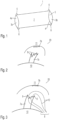
- Fig. 1 shows a preferred embodiment of the implant 1 according to the invention for use in a joint to support a ligament, for example the anterior cruciate ligament of a human knee joint.
- the implant 1 has a coherent support body 2, which in the present exemplary embodiment is essentially tubular or hose-shaped.
- the support body can also have a different geometric shape.
- the support body has an inner, preferably cylindrical, cavity 5, which is enclosed by an outer wall 4. Openings 3a, 3b are provided in the outer wall 4 at opposite ends of the support body. A ligament to be supported or guided can thus be guided through the openings 3a, 3b and through the inner cavity 5.
- the outer wall 4 of the support body 2 is designed to prevent diffusion, preferably in such a way as to greatly restrict or prevent liquid transport from the cavity 5 of the support body to the surroundings of the implant 1. This allows for the formation of a primary healing matrix inside the cavity and in close proximity to the guided ligament.
- the support body 2 can have a net-shaped, foam-like or gel-like structure.
- the support body can, for example, consist of a tightly woven material.
- the cavity 5 is preferably designed with respect to its internal dimensions in such a way that an inner wall 4a of the cavity 5 tightly laterally encloses a ligament to be guided.
- the support body 2 can at least partially consist of elastic material. This ensures optimal adaptation of the support body 2 to the outer contours of the ligament to be guided.
- the implant 1 can optionally have fastening means 6 for fastening and positioning the implant to a bone. These can be formed by eyelets 6 be, which are attached to opposite ends of the support body or integrally formed with the support body.
- the support body 2 preferably consists of a material that can be absorbed by the human body.
- the material of the support body 2 can include, for example, collagen type 1 or 2, polyurethane and/or polyglycolic acid.
- the support body 2 can at least partially have a substance that promotes the growth of a ligament. This can be incorporated into the material of the outer wall of the support body and/or applied to the inner surface 4a of the outer wall, which delimits the cavity 5.
- Fig. 2 is a schematic representation of a human knee joint 20 and shows a proximally torn cruciate ligament 7a, 7b between the femur and tibia bones 10,11.
- the lower torn section 7a of the cruciate ligament is attached to the tibia bone 10.
- the counterpart 7b of the cruciate ligament is attached to the femur 11.
- This counterpart 7b represents a femoral "footprint" of the cruciate ligament, to which the proximally torn section 7a of the cruciate ligament is to be attached.
- the stumps or torn fiber ends 9 of the cruciate ligament piece 7a are first grasped with the help of one or more seams 12 inserted into the knee joint 20.
- the seam or seams 12 are pierced through the fiber ends 9.
- the implant 1 is then applied to the cruciate ligament section 7a using the at least one seam 12. This can be done, for example, by the respective Ends of the seams 12 are formed into a loop 8, over which the implant 1 can be pushed towards the fiber ends 9 by means of the openings 3a, 3b and placed over the cruciate ligament section 7a (see Figs. 4 and 5 ).
- the implant 1 is positioned in such a way that the cruciate ligament section 7a is guided within the cavity 5 of the preferably tubular support body 2.
- the inner wall 4a of the support body preferably rests closely on the circumference of the cruciate ligament section 7a. Splinting of the cruciate ligament section 7a is therefore achieved with the aid of the attached implant 1 as well as alignment or adaptation of the cruciate ligament stumps 9. Due to the weight of the implant 1, it rests on the shin bone 10.
- Grasping the cruciate ligament stumps 9 and sheathing the torn cruciate ligament section 7a is preferably done with the help of an arthroscopic applicator.
- the torn cruciate ligament section 7a is then anatomically repositioned to the femoral “footprint” 7b of the cruciate ligament on the thigh bone 11, as in Fig. 6 shown.
- the torn section 7a or its fiber ends 9 is stretched to the thigh bone 11 with the help of the seam or seams 12 and attached to it.
- This can be done, for example, with the help of a fastening hole 11a provided in the bone 11, which must be drilled into the bone beforehand.
- the seam or seams 12 can be fixed therein using conventional connecting techniques such as knotting the seam ends 13.
- Anchors or bolts are inserted into the bone to fix the suture 12 to it.
- the implant can position itself between the thigh bone 11 and the tibia bone 10, for example due to its own elasticity.
- the openings 3a, 3b of the implant 1 preferably lie on the femur 11 or on the tibia bone 10.
- the inner wall 4a of the implant 1 lies closely against the restored cruciate ligament 7a, 7b, thereby guiding and supporting the cruciate ligament 7a, 7b.
- the diffusion-preventing outer wall 4 of the implant enables the local formation of a primary healing matrix inside the implant and along the restored cruciate ligament 7a, 7b.
- additional growth factors or healing-promoting substances can be introduced into the cavity 5 of the implant 1 by injection, for example using a syringe.
- These can include the following substances: Fresh blood for coagulation in the supporting body 2, blood from the medullary canal with pluripotent stem cells, fibrin, extracellular matrix proteins, vitronectin, stem cells from your own fat, growth factors, cytokines, HGF (Human Growth Factor), Interleukin-1, IL- 3, IL-6, IL-11, PDGF (platelet derived growth factor), FGF (fibroblast growth factor), EGF (epidermal growth factor), VEGF (vascular endothelial growth factor), PRP (platelet rich plasma), PRF (plateler rich fibrin), and/or angiopoietins.
- the substance introduced is held within the cavity 5 by the diffusion-preventing outer wall 4. This is particularly the case with introduced stem cells advantageous because these can promote negative effects such as undesirable cartilage growth if they are transported to another location on the knee joint or the human body.
- the inner wall 4a of the implant can be coated with one or more of the substances mentioned above.
- fixation seams 14 can be provided, which are attached between the implant 1 and one or both of the bones 10, 11.
- the fixing seams 14 can, for example, be attached to optional fasteners 6 of the implant (see Fig. 1 ) can be attached.
- the fixing sutures 14 can be attached to the bones 10, 11 using known methods. For example, drill holes and/or bolts can be provided in the respective bones 10, 11 to fasten the seams 14.
- the openings 3a, 3b preferably lie directly on the femur or tibia bone 10, 11.
- the invention is not limited to the exemplary embodiments shown. It is suitable not only for treating the cruciate ligament, but also for treating other ligaments of the knee joint and other joints, such as the elbow joint or the shoulder joint. It is also suitable not only for the human body but also for the animal body.
Landscapes
- Health & Medical Sciences (AREA)
- Orthopedic Medicine & Surgery (AREA)
- Rehabilitation Therapy (AREA)
- Rheumatology (AREA)
- Cardiology (AREA)
- Oral & Maxillofacial Surgery (AREA)
- Transplantation (AREA)
- Engineering & Computer Science (AREA)
- Biomedical Technology (AREA)
- Heart & Thoracic Surgery (AREA)
- Vascular Medicine (AREA)
- Life Sciences & Earth Sciences (AREA)
- Animal Behavior & Ethology (AREA)
- General Health & Medical Sciences (AREA)
- Public Health (AREA)
- Veterinary Medicine (AREA)
- Prostheses (AREA)
Claims (11)
- Un implant (1) destiné à être utilisé dans une articulation (20) pour soutenir un ligament (7a, 7b), comportantun corps de soutien cohésif (2) qui comprend une cavité intérieure (5) et qui est conçu pour guider un ligament (7a, 7b) de l'articulation (20), etune première et une seconde ouverture (3a, 3b) dans une paroi extérieure (4) du corps de soutien,dans lequel la paroi extérieure (4) du corps de soutien (2) est conçue pour empêcher la diffusion, de sorte qu'un transport de liquide est empêché de la cavité intérieure (5) vers l'environnement de l'implant (1),caractérisé en ce quele diamètre intérieur de la cavité (5) du corps de soutien (2) est adapté à l'extension latérale du ligament (7a, 7b) et une paroi intérieure (4a) de la cavité (5) entoure étroitement un ligament (7a, 7b) à guider sur la circonférence, de sorte que la formation d'une matrice de cicatrisation primaire est possible autour du ligament (7a, 7b) guidé dans la cavité, eten ce que un ou plusieurs facteurs de croissance et/ou une ou plusieurs substances favorisant la cicatrisation peuvent être injectés dans la cavité interne (5) par des moyens d'injection (15), eten ce que les première et seconde ouvertures (3a, 3b) sont disposées à des extrémités opposées du corps de soutien (2) et sont reliées à la cavité (5) du corps de soutien.
- L'implant selon la revendication 1,
dans lequel le corps de soutien (2) est au moins en partie constitué d'un matériau élastique. - L'implant selon la revendication 1 ou 2,
dans lequel le corps de soutien (2) est sensiblement tubulaire ou en forme de ballonnet. - L'implant selon l'une des revendications 1 à 3,
dans lequel le corps de soutien (2) a une structure réticulaire, analogue à une mousse ou analogue à un gel. - L'implant selon l'une des revendications précédentes,
dans lequel le corps de soutien (2) est constitué d'un matériau tissé à mailles serrées. - L'implant selon l'une des revendications précédentes,
dans lequel le corps de soutien (2) est constitué d'un matériau résorbable par le corps humain ou animal. - L'implant selon l'une des revendications précédentes,
dans lequel le matériau du corps de soutien (2) comprend un ou plusieurs des matériaux suivants : collagène de type 1 ou 2, polyuréthane, acide polycyclique. - L'implant selon l'une des revendications précédentes,
dans lequel le corps de soutien (2) comporte au moins en partie une substance favorisant la croissance d'un ligament (7a, 7b). - L'implant selon la revendication 8,
dans lequel une surface intérieure (4a) de la paroi extérieure (4) du corps de soutien (2) est au moins partiellement revêtue de la substance favorisant la croissance. - L'implant selon la revendication 8 ou 9,
dans lequel la substance favorisant la croissance comprend une ou plusieurs des substances suivantes : cellules souches pluripotentes, fibrine, protéines matricielles extra-cellulaires, vitronectine, cellules souches de graisse autologue, facteurs de croissance, cytokines, HGF (facteur de croissance humain), interleukine-1, IL-3, IL-6, IL-11, PDGF (facteur de croissance dérivé des plaquettes), FGF (facteur de croissance des fibroblastes), EGF (facteur de croissance épidermique), VEGF (facteur de croissance endothéliale vasculaire), PRP (plasma riche en plaquettes), PRE (fibrine riche en plaquettes) et/ou angiopoiétine. - L'implant selon l'une des revendications précédentes, dans lequel le corps de soutien (2) comporte, au niveau des deux extrémités opposées, des moyens de fixation (6) pour la fixation et le positionnement sur un os (10, 11).
Applications Claiming Priority (2)
| Application Number | Priority Date | Filing Date | Title |
|---|---|---|---|
| DE102015225218.3A DE102015225218B4 (de) | 2015-12-15 | 2015-12-15 | Implantat für den Einsatz in ein Gelenk zur Stützung eines Ligaments |
| PCT/EP2016/077150 WO2017102184A1 (fr) | 2015-12-15 | 2016-11-09 | Implant de maintien pour ligament |
Publications (3)
| Publication Number | Publication Date |
|---|---|
| EP3389558A1 EP3389558A1 (fr) | 2018-10-24 |
| EP3389558C0 EP3389558C0 (fr) | 2024-03-06 |
| EP3389558B1 true EP3389558B1 (fr) | 2024-03-06 |
Family
ID=57389386
Family Applications (1)
| Application Number | Title | Priority Date | Filing Date |
|---|---|---|---|
| EP16798659.5A Active EP3389558B1 (fr) | 2015-12-15 | 2016-11-09 | Implant de maintien pour ligament |
Country Status (3)
| Country | Link |
|---|---|
| EP (1) | EP3389558B1 (fr) |
| DE (1) | DE102015225218B4 (fr) |
| WO (1) | WO2017102184A1 (fr) |
Citations (1)
| Publication number | Priority date | Publication date | Assignee | Title |
|---|---|---|---|---|
| US3613120A (en) * | 1969-10-21 | 1971-10-19 | Research Corp | Flexor tendon prosthesis |
Family Cites Families (11)
| Publication number | Priority date | Publication date | Assignee | Title |
|---|---|---|---|---|
| US4455690A (en) * | 1980-11-06 | 1984-06-26 | Homsy Charles A | Structure for in vivo implanation |
| US4739751A (en) | 1986-10-03 | 1988-04-26 | Temple University | Apparatus and method for reconstructive surgery |
| US5702422A (en) | 1995-12-06 | 1997-12-30 | Stone; Kevin R. | Anterior cruciate ligament repair method |
| US8226715B2 (en) * | 2003-06-30 | 2012-07-24 | Depuy Mitek, Inc. | Scaffold for connective tissue repair |
| US8137382B2 (en) * | 2004-11-05 | 2012-03-20 | Biomet Sports Medicine, Llc | Method and apparatus for coupling anatomical features |
| US7749250B2 (en) * | 2006-02-03 | 2010-07-06 | Biomet Sports Medicine, Llc | Soft tissue repair assembly and associated method |
| AU2007204815A1 (en) * | 2006-01-12 | 2007-07-19 | Histogenics Corporation | Method for repair and reconstruction of ruptured ligaments or tendons and for treatment of ligament and tendon injuries |
| US8585753B2 (en) * | 2006-03-04 | 2013-11-19 | John James Scanlon | Fibrillated biodegradable prosthesis |
| US20090157193A1 (en) | 2007-12-18 | 2009-06-18 | Warsaw Orthopedic, Inc. | Tendon and Ligament Repair Sheet and Methods of Use |
| WO2013040325A1 (fr) * | 2011-09-15 | 2013-03-21 | Arsenal Medical, Inc. | Implants pour douleur postopératoire |
| CN203953876U (zh) | 2014-03-07 | 2014-11-26 | 复旦大学附属华山医院 | 中空管带状可折叠悬吊式人工韧带 |
-
2015
- 2015-12-15 DE DE102015225218.3A patent/DE102015225218B4/de active Active
-
2016
- 2016-11-09 EP EP16798659.5A patent/EP3389558B1/fr active Active
- 2016-11-09 WO PCT/EP2016/077150 patent/WO2017102184A1/fr not_active Ceased
Patent Citations (1)
| Publication number | Priority date | Publication date | Assignee | Title |
|---|---|---|---|---|
| US3613120A (en) * | 1969-10-21 | 1971-10-19 | Research Corp | Flexor tendon prosthesis |
Also Published As
| Publication number | Publication date |
|---|---|
| WO2017102184A1 (fr) | 2017-06-22 |
| EP3389558C0 (fr) | 2024-03-06 |
| DE102015225218A1 (de) | 2017-06-22 |
| DE102015225218B4 (de) | 2023-03-09 |
| EP3389558A1 (fr) | 2018-10-24 |
Similar Documents
| Publication | Publication Date | Title |
|---|---|---|
| DE60132135T2 (de) | Verwendung einer Klebesubstanz zur Herstellung eines Knochenklebestoffes zur Befestigung eines Knochenstopfens in einem Knochenkanal | |
| EP1334702B1 (fr) | Elément d'ancrage pour ancrer un greffon de ligament | |
| DE69832800T2 (de) | Chirugische hilfe zur gewebetransplantation | |
| DE60022590T2 (de) | Befestigungsvorrichtung und -verfahren für ein Transplantat | |
| DE60122885T2 (de) | Fixierungsanker | |
| DE69209262T2 (de) | Vorrichtung zum verstärken eines ligamenttransplantats in der wiederherstellungschirurgie | |
| DE69826688T2 (de) | Vorrichtung zum verankern von körpereigenen oder künstlichen sehnentransplantaten in knochen | |
| DE69433138T2 (de) | Fadenverankerungsvorrichtung | |
| DE102008016607B4 (de) | Vorrichtung zur Implantation in einen Knochen und ein System für eine Beanspruchung eines rekonstruierten vorderen Kreuzbands während der Heilungsphase aufweisend die Vorrichtung | |
| DE102009051367B4 (de) | Implantierbares System mit kontinuierlichem Auflösungsmechanismus bei der Ausheilung | |
| DE69734606T2 (de) | Vorrichtung zur befestigung von körpereigenen oder künstlichen sehnentransplantaten in knochen | |
| DE69617423T2 (de) | Gelenkprothese | |
| DE60013768T2 (de) | Weichgewebsbefestigung | |
| DE69232266T2 (de) | Transplantat zur unterstützung von autogenem gewebewachstum | |
| EP2086437B1 (fr) | Implant pour os tubulaires | |
| EP3389558B1 (fr) | Implant de maintien pour ligament | |
| US20230380955A1 (en) | Combination therapy for tissue repair | |
| CN209916298U (zh) | 一种用于韧带或肌腱的固定装置 | |
| JP7034983B2 (ja) | コラーゲン構築物、およびコラーゲン構築物を生成する方法 | |
| US20250025288A1 (en) | Graft and scaffold acl repair system | |
| US20250366843A1 (en) | Bioinductive collagen anchor for tissue repair | |
| RU2340301C2 (ru) | Способ пластики ахиллова сухожилия | |
| RU2750464C1 (ru) | Артроскопическое протезирование передней крестовидной связки у собак | |
| DE102023130257A1 (de) | Endo-Exo-Prothese für Gliedmaßen | |
| DE102004032115B4 (de) | Implantat zur Erhöhung der Ausrissfestigkeit von Sehnennähten |
Legal Events
| Date | Code | Title | Description |
|---|---|---|---|
| STAA | Information on the status of an ep patent application or granted ep patent |
Free format text: STATUS: UNKNOWN |
|
| STAA | Information on the status of an ep patent application or granted ep patent |
Free format text: STATUS: THE INTERNATIONAL PUBLICATION HAS BEEN MADE |
|
| PUAI | Public reference made under article 153(3) epc to a published international application that has entered the european phase |
Free format text: ORIGINAL CODE: 0009012 |
|
| STAA | Information on the status of an ep patent application or granted ep patent |
Free format text: STATUS: REQUEST FOR EXAMINATION WAS MADE |
|
| 17P | Request for examination filed |
Effective date: 20180605 |
|
| AK | Designated contracting states |
Kind code of ref document: A1 Designated state(s): AL AT BE BG CH CY CZ DE DK EE ES FI FR GB GR HR HU IE IS IT LI LT LU LV MC MK MT NL NO PL PT RO RS SE SI SK SM TR |
|
| AX | Request for extension of the european patent |
Extension state: BA ME |
|
| DAV | Request for validation of the european patent (deleted) | ||
| DAX | Request for extension of the european patent (deleted) | ||
| STAA | Information on the status of an ep patent application or granted ep patent |
Free format text: STATUS: EXAMINATION IS IN PROGRESS |
|
| 17Q | First examination report despatched |
Effective date: 20210205 |
|
| GRAP | Despatch of communication of intention to grant a patent |
Free format text: ORIGINAL CODE: EPIDOSNIGR1 |
|
| STAA | Information on the status of an ep patent application or granted ep patent |
Free format text: STATUS: GRANT OF PATENT IS INTENDED |
|
| INTG | Intention to grant announced |
Effective date: 20231018 |
|
| GRAS | Grant fee paid |
Free format text: ORIGINAL CODE: EPIDOSNIGR3 |
|
| GRAA | (expected) grant |
Free format text: ORIGINAL CODE: 0009210 |
|
| STAA | Information on the status of an ep patent application or granted ep patent |
Free format text: STATUS: THE PATENT HAS BEEN GRANTED |
|
| AK | Designated contracting states |
Kind code of ref document: B1 Designated state(s): AL AT BE BG CH CY CZ DE DK EE ES FI FR GB GR HR HU IE IS IT LI LT LU LV MC MK MT NL NO PL PT RO RS SE SI SK SM TR |
|
| REG | Reference to a national code |
Ref country code: GB Ref legal event code: FG4D Free format text: NOT ENGLISH |
|
| REG | Reference to a national code |
Ref country code: CH Ref legal event code: EP |
|
| REG | Reference to a national code |
Ref country code: DE Ref legal event code: R096 Ref document number: 502016016409 Country of ref document: DE |
|
| REG | Reference to a national code |
Ref country code: IE Ref legal event code: FG4D Free format text: LANGUAGE OF EP DOCUMENT: GERMAN |
|
| U01 | Request for unitary effect filed |
Effective date: 20240308 |
|
| U07 | Unitary effect registered |
Designated state(s): AT BE BG DE DK EE FI FR IT LT LU LV MT NL PT SE SI Effective date: 20240318 |
|
| PG25 | Lapsed in a contracting state [announced via postgrant information from national office to epo] |
Ref country code: GR Free format text: LAPSE BECAUSE OF FAILURE TO SUBMIT A TRANSLATION OF THE DESCRIPTION OR TO PAY THE FEE WITHIN THE PRESCRIBED TIME-LIMIT Effective date: 20240607 |
|
| PG25 | Lapsed in a contracting state [announced via postgrant information from national office to epo] |
Ref country code: HR Free format text: LAPSE BECAUSE OF FAILURE TO SUBMIT A TRANSLATION OF THE DESCRIPTION OR TO PAY THE FEE WITHIN THE PRESCRIBED TIME-LIMIT Effective date: 20240306 Ref country code: RS Free format text: LAPSE BECAUSE OF FAILURE TO SUBMIT A TRANSLATION OF THE DESCRIPTION OR TO PAY THE FEE WITHIN THE PRESCRIBED TIME-LIMIT Effective date: 20240606 |
|
| PG25 | Lapsed in a contracting state [announced via postgrant information from national office to epo] |
Ref country code: ES Free format text: LAPSE BECAUSE OF FAILURE TO SUBMIT A TRANSLATION OF THE DESCRIPTION OR TO PAY THE FEE WITHIN THE PRESCRIBED TIME-LIMIT Effective date: 20240306 |
|
| PG25 | Lapsed in a contracting state [announced via postgrant information from national office to epo] |
Ref country code: RS Free format text: LAPSE BECAUSE OF FAILURE TO SUBMIT A TRANSLATION OF THE DESCRIPTION OR TO PAY THE FEE WITHIN THE PRESCRIBED TIME-LIMIT Effective date: 20240606 Ref country code: NO Free format text: LAPSE BECAUSE OF FAILURE TO SUBMIT A TRANSLATION OF THE DESCRIPTION OR TO PAY THE FEE WITHIN THE PRESCRIBED TIME-LIMIT Effective date: 20240606 Ref country code: HR Free format text: LAPSE BECAUSE OF FAILURE TO SUBMIT A TRANSLATION OF THE DESCRIPTION OR TO PAY THE FEE WITHIN THE PRESCRIBED TIME-LIMIT Effective date: 20240306 Ref country code: GR Free format text: LAPSE BECAUSE OF FAILURE TO SUBMIT A TRANSLATION OF THE DESCRIPTION OR TO PAY THE FEE WITHIN THE PRESCRIBED TIME-LIMIT Effective date: 20240607 Ref country code: ES Free format text: LAPSE BECAUSE OF FAILURE TO SUBMIT A TRANSLATION OF THE DESCRIPTION OR TO PAY THE FEE WITHIN THE PRESCRIBED TIME-LIMIT Effective date: 20240306 |
|
| PG25 | Lapsed in a contracting state [announced via postgrant information from national office to epo] |
Ref country code: IS Free format text: LAPSE BECAUSE OF FAILURE TO SUBMIT A TRANSLATION OF THE DESCRIPTION OR TO PAY THE FEE WITHIN THE PRESCRIBED TIME-LIMIT Effective date: 20240706 |
|
| PG25 | Lapsed in a contracting state [announced via postgrant information from national office to epo] |
Ref country code: SM Free format text: LAPSE BECAUSE OF FAILURE TO SUBMIT A TRANSLATION OF THE DESCRIPTION OR TO PAY THE FEE WITHIN THE PRESCRIBED TIME-LIMIT Effective date: 20240306 |
|
| PG25 | Lapsed in a contracting state [announced via postgrant information from national office to epo] |
Ref country code: CZ Free format text: LAPSE BECAUSE OF FAILURE TO SUBMIT A TRANSLATION OF THE DESCRIPTION OR TO PAY THE FEE WITHIN THE PRESCRIBED TIME-LIMIT Effective date: 20240306 |
|
| PG25 | Lapsed in a contracting state [announced via postgrant information from national office to epo] |
Ref country code: PL Free format text: LAPSE BECAUSE OF FAILURE TO SUBMIT A TRANSLATION OF THE DESCRIPTION OR TO PAY THE FEE WITHIN THE PRESCRIBED TIME-LIMIT Effective date: 20240306 |
|
| PG25 | Lapsed in a contracting state [announced via postgrant information from national office to epo] |
Ref country code: SK Free format text: LAPSE BECAUSE OF FAILURE TO SUBMIT A TRANSLATION OF THE DESCRIPTION OR TO PAY THE FEE WITHIN THE PRESCRIBED TIME-LIMIT Effective date: 20240306 |
|
| PG25 | Lapsed in a contracting state [announced via postgrant information from national office to epo] |
Ref country code: SM Free format text: LAPSE BECAUSE OF FAILURE TO SUBMIT A TRANSLATION OF THE DESCRIPTION OR TO PAY THE FEE WITHIN THE PRESCRIBED TIME-LIMIT Effective date: 20240306 Ref country code: SK Free format text: LAPSE BECAUSE OF FAILURE TO SUBMIT A TRANSLATION OF THE DESCRIPTION OR TO PAY THE FEE WITHIN THE PRESCRIBED TIME-LIMIT Effective date: 20240306 Ref country code: RO Free format text: LAPSE BECAUSE OF FAILURE TO SUBMIT A TRANSLATION OF THE DESCRIPTION OR TO PAY THE FEE WITHIN THE PRESCRIBED TIME-LIMIT Effective date: 20240306 Ref country code: PL Free format text: LAPSE BECAUSE OF FAILURE TO SUBMIT A TRANSLATION OF THE DESCRIPTION OR TO PAY THE FEE WITHIN THE PRESCRIBED TIME-LIMIT Effective date: 20240306 Ref country code: IS Free format text: LAPSE BECAUSE OF FAILURE TO SUBMIT A TRANSLATION OF THE DESCRIPTION OR TO PAY THE FEE WITHIN THE PRESCRIBED TIME-LIMIT Effective date: 20240706 Ref country code: CZ Free format text: LAPSE BECAUSE OF FAILURE TO SUBMIT A TRANSLATION OF THE DESCRIPTION OR TO PAY THE FEE WITHIN THE PRESCRIBED TIME-LIMIT Effective date: 20240306 |
|
| REG | Reference to a national code |
Ref country code: DE Ref legal event code: R097 Ref document number: 502016016409 Country of ref document: DE |
|
| U20 | Renewal fee for the european patent with unitary effect paid |
Year of fee payment: 9 Effective date: 20241126 |
|
| PLBE | No opposition filed within time limit |
Free format text: ORIGINAL CODE: 0009261 |
|
| STAA | Information on the status of an ep patent application or granted ep patent |
Free format text: STATUS: NO OPPOSITION FILED WITHIN TIME LIMIT |
|
| 26N | No opposition filed |
Effective date: 20241209 |
|
| PG25 | Lapsed in a contracting state [announced via postgrant information from national office to epo] |
Ref country code: MC Free format text: LAPSE BECAUSE OF FAILURE TO SUBMIT A TRANSLATION OF THE DESCRIPTION OR TO PAY THE FEE WITHIN THE PRESCRIBED TIME-LIMIT Effective date: 20240306 |
|
| GBPC | Gb: european patent ceased through non-payment of renewal fee |
Effective date: 20241109 |
|
| PG25 | Lapsed in a contracting state [announced via postgrant information from national office to epo] |
Ref country code: GB Free format text: LAPSE BECAUSE OF NON-PAYMENT OF DUE FEES Effective date: 20241109 |
|
| PG25 | Lapsed in a contracting state [announced via postgrant information from national office to epo] |
Ref country code: IE Free format text: LAPSE BECAUSE OF NON-PAYMENT OF DUE FEES Effective date: 20241109 |
|
| REG | Reference to a national code |
Ref country code: CH Ref legal event code: U11 Free format text: ST27 STATUS EVENT CODE: U-0-0-U10-U11 (AS PROVIDED BY THE NATIONAL OFFICE) Effective date: 20251201 |
|
| U20 | Renewal fee for the european patent with unitary effect paid |
Year of fee payment: 10 Effective date: 20251105 |
|
| PGFP | Annual fee paid to national office [announced via postgrant information from national office to epo] |
Ref country code: CH Payment date: 20251201 Year of fee payment: 10 |
|
| PG25 | Lapsed in a contracting state [announced via postgrant information from national office to epo] |
Ref country code: HU Free format text: LAPSE BECAUSE OF FAILURE TO SUBMIT A TRANSLATION OF THE DESCRIPTION OR TO PAY THE FEE WITHIN THE PRESCRIBED TIME-LIMIT; INVALID AB INITIO Effective date: 20161109 |
|
| PG25 | Lapsed in a contracting state [announced via postgrant information from national office to epo] |
Ref country code: CY Free format text: LAPSE BECAUSE OF FAILURE TO SUBMIT A TRANSLATION OF THE DESCRIPTION OR TO PAY THE FEE WITHIN THE PRESCRIBED TIME-LIMIT; INVALID AB INITIO Effective date: 20161109 |