EP3390899B1 - Projecteur additionnel pour véhicules - Google Patents
Projecteur additionnel pour véhicules Download PDFInfo
- Publication number
- EP3390899B1 EP3390899B1 EP16819419.9A EP16819419A EP3390899B1 EP 3390899 B1 EP3390899 B1 EP 3390899B1 EP 16819419 A EP16819419 A EP 16819419A EP 3390899 B1 EP3390899 B1 EP 3390899B1
- Authority
- EP
- European Patent Office
- Prior art keywords
- light
- headlamp
- auxiliary
- module
- headlight
- Prior art date
- Legal status (The legal status is an assumption and is not a legal conclusion. Google has not performed a legal analysis and makes no representation as to the accuracy of the status listed.)
- Active
Links
Images




Classifications
-
- F—MECHANICAL ENGINEERING; LIGHTING; HEATING; WEAPONS; BLASTING
- F21—LIGHTING
- F21S—NON-PORTABLE LIGHTING DEVICES; SYSTEMS THEREOF; VEHICLE LIGHTING DEVICES SPECIALLY ADAPTED FOR VEHICLE EXTERIORS
- F21S41/00—Illuminating devices specially adapted for vehicle exteriors, e.g. headlamps
- F21S41/20—Illuminating devices specially adapted for vehicle exteriors, e.g. headlamps characterised by refractors, transparent cover plates, light guides or filters
- F21S41/24—Light guides
-
- B—PERFORMING OPERATIONS; TRANSPORTING
- B60—VEHICLES IN GENERAL
- B60Q—ARRANGEMENT OF SIGNALLING OR LIGHTING DEVICES, THE MOUNTING OR SUPPORTING THEREOF OR CIRCUITS THEREFOR, FOR VEHICLES IN GENERAL
- B60Q1/00—Arrangement of optical signalling or lighting devices, the mounting or supporting thereof or circuits therefor
- B60Q1/02—Arrangement of optical signalling or lighting devices, the mounting or supporting thereof or circuits therefor the devices being primarily intended to illuminate the way ahead or to illuminate other areas of way or environments
- B60Q1/04—Arrangement of optical signalling or lighting devices, the mounting or supporting thereof or circuits therefor the devices being primarily intended to illuminate the way ahead or to illuminate other areas of way or environments the devices being headlights
- B60Q1/18—Arrangement of optical signalling or lighting devices, the mounting or supporting thereof or circuits therefor the devices being primarily intended to illuminate the way ahead or to illuminate other areas of way or environments the devices being headlights being additional front lights
-
- B—PERFORMING OPERATIONS; TRANSPORTING
- B60—VEHICLES IN GENERAL
- B60Q—ARRANGEMENT OF SIGNALLING OR LIGHTING DEVICES, THE MOUNTING OR SUPPORTING THEREOF OR CIRCUITS THEREFOR, FOR VEHICLES IN GENERAL
- B60Q1/00—Arrangement of optical signalling or lighting devices, the mounting or supporting thereof or circuits therefor
- B60Q1/02—Arrangement of optical signalling or lighting devices, the mounting or supporting thereof or circuits therefor the devices being primarily intended to illuminate the way ahead or to illuminate other areas of way or environments
- B60Q1/24—Arrangement of optical signalling or lighting devices, the mounting or supporting thereof or circuits therefor the devices being primarily intended to illuminate the way ahead or to illuminate other areas of way or environments for lighting other areas than only the way ahead
-
- F—MECHANICAL ENGINEERING; LIGHTING; HEATING; WEAPONS; BLASTING
- F21—LIGHTING
- F21S—NON-PORTABLE LIGHTING DEVICES; SYSTEMS THEREOF; VEHICLE LIGHTING DEVICES SPECIALLY ADAPTED FOR VEHICLE EXTERIORS
- F21S41/00—Illuminating devices specially adapted for vehicle exteriors, e.g. headlamps
- F21S41/20—Illuminating devices specially adapted for vehicle exteriors, e.g. headlamps characterised by refractors, transparent cover plates, light guides or filters
- F21S41/29—Attachment thereof
-
- F—MECHANICAL ENGINEERING; LIGHTING; HEATING; WEAPONS; BLASTING
- F21—LIGHTING
- F21S—NON-PORTABLE LIGHTING DEVICES; SYSTEMS THEREOF; VEHICLE LIGHTING DEVICES SPECIALLY ADAPTED FOR VEHICLE EXTERIORS
- F21S41/00—Illuminating devices specially adapted for vehicle exteriors, e.g. headlamps
- F21S41/60—Illuminating devices specially adapted for vehicle exteriors, e.g. headlamps characterised by a variable light distribution
- F21S41/65—Illuminating devices specially adapted for vehicle exteriors, e.g. headlamps characterised by a variable light distribution by acting on light sources
-
- F—MECHANICAL ENGINEERING; LIGHTING; HEATING; WEAPONS; BLASTING
- F21—LIGHTING
- F21S—NON-PORTABLE LIGHTING DEVICES; SYSTEMS THEREOF; VEHICLE LIGHTING DEVICES SPECIALLY ADAPTED FOR VEHICLE EXTERIORS
- F21S41/00—Illuminating devices specially adapted for vehicle exteriors, e.g. headlamps
- F21S41/60—Illuminating devices specially adapted for vehicle exteriors, e.g. headlamps characterised by a variable light distribution
- F21S41/65—Illuminating devices specially adapted for vehicle exteriors, e.g. headlamps characterised by a variable light distribution by acting on light sources
- F21S41/663—Illuminating devices specially adapted for vehicle exteriors, e.g. headlamps characterised by a variable light distribution by acting on light sources by switching light sources
-
- F—MECHANICAL ENGINEERING; LIGHTING; HEATING; WEAPONS; BLASTING
- F21—LIGHTING
- F21S—NON-PORTABLE LIGHTING DEVICES; SYSTEMS THEREOF; VEHICLE LIGHTING DEVICES SPECIALLY ADAPTED FOR VEHICLE EXTERIORS
- F21S41/00—Illuminating devices specially adapted for vehicle exteriors, e.g. headlamps
- F21S41/10—Illuminating devices specially adapted for vehicle exteriors, e.g. headlamps characterised by the light source
- F21S41/14—Illuminating devices specially adapted for vehicle exteriors, e.g. headlamps characterised by the light source characterised by the type of light source
- F21S41/141—Light emitting diodes [LED]
-
- F—MECHANICAL ENGINEERING; LIGHTING; HEATING; WEAPONS; BLASTING
- F21—LIGHTING
- F21S—NON-PORTABLE LIGHTING DEVICES; SYSTEMS THEREOF; VEHICLE LIGHTING DEVICES SPECIALLY ADAPTED FOR VEHICLE EXTERIORS
- F21S41/00—Illuminating devices specially adapted for vehicle exteriors, e.g. headlamps
- F21S41/10—Illuminating devices specially adapted for vehicle exteriors, e.g. headlamps characterised by the light source
- F21S41/14—Illuminating devices specially adapted for vehicle exteriors, e.g. headlamps characterised by the light source characterised by the type of light source
- F21S41/141—Light emitting diodes [LED]
- F21S41/143—Light emitting diodes [LED] the main emission direction of the LED being parallel to the optical axis of the illuminating device
-
- F—MECHANICAL ENGINEERING; LIGHTING; HEATING; WEAPONS; BLASTING
- F21—LIGHTING
- F21S—NON-PORTABLE LIGHTING DEVICES; SYSTEMS THEREOF; VEHICLE LIGHTING DEVICES SPECIALLY ADAPTED FOR VEHICLE EXTERIORS
- F21S41/00—Illuminating devices specially adapted for vehicle exteriors, e.g. headlamps
- F21S41/10—Illuminating devices specially adapted for vehicle exteriors, e.g. headlamps characterised by the light source
- F21S41/14—Illuminating devices specially adapted for vehicle exteriors, e.g. headlamps characterised by the light source characterised by the type of light source
- F21S41/141—Light emitting diodes [LED]
- F21S41/151—Light emitting diodes [LED] arranged in one or more lines
- F21S41/153—Light emitting diodes [LED] arranged in one or more lines arranged in a matrix
-
- F—MECHANICAL ENGINEERING; LIGHTING; HEATING; WEAPONS; BLASTING
- F21—LIGHTING
- F21S—NON-PORTABLE LIGHTING DEVICES; SYSTEMS THEREOF; VEHICLE LIGHTING DEVICES SPECIALLY ADAPTED FOR VEHICLE EXTERIORS
- F21S41/00—Illuminating devices specially adapted for vehicle exteriors, e.g. headlamps
- F21S41/20—Illuminating devices specially adapted for vehicle exteriors, e.g. headlamps characterised by refractors, transparent cover plates, light guides or filters
- F21S41/25—Projection lenses
- F21S41/255—Lenses with a front view of circular or truncated circular outline
-
- F—MECHANICAL ENGINEERING; LIGHTING; HEATING; WEAPONS; BLASTING
- F21—LIGHTING
- F21Y—INDEXING SCHEME ASSOCIATED WITH SUBCLASSES F21K, F21L, F21S and F21V, RELATING TO THE FORM OR THE KIND OF THE LIGHT SOURCES OR OF THE COLOUR OF THE LIGHT EMITTED
- F21Y2103/00—Elongate light sources, e.g. fluorescent tubes
- F21Y2103/10—Elongate light sources, e.g. fluorescent tubes comprising a linear array of point-like light-generating elements
-
- F—MECHANICAL ENGINEERING; LIGHTING; HEATING; WEAPONS; BLASTING
- F21—LIGHTING
- F21Y—INDEXING SCHEME ASSOCIATED WITH SUBCLASSES F21K, F21L, F21S and F21V, RELATING TO THE FORM OR THE KIND OF THE LIGHT SOURCES OR OF THE COLOUR OF THE LIGHT EMITTED
- F21Y2105/00—Planar light sources
- F21Y2105/10—Planar light sources comprising a two-dimensional [2D] array of point-like light-generating elements
- F21Y2105/12—Planar light sources comprising a two-dimensional [2D] array of point-like light-generating elements characterised by the geometrical disposition of the light-generating elements, e.g. arranging light-generating elements in differing patterns or densities
Definitions
- the invention relates to an additional headlight for a vehicle which is set up to generate a light image in front of the vehicle by emitting light from at least one light module and to project it in front of the vehicle through a downstream imaging optics.
- the focus is increasingly on the desire to be able to project a light image onto the roadway that can be quickly changed and adapted to the respective traffic, road and light conditions.
- different headlights for example main and auxiliary headlights, are used, which generate different light images on the roadway.
- the term “roadway” is used here for a simplified representation, because of course it depends on the local conditions whether a photograph is actually located on the roadway or whether it extends beyond it.
- the light image in the sense used corresponds to a projection onto a vertical surface in accordance with the relevant standards that relate to vehicle lighting technology.
- headlights were developed, among other things, which form a light matrix from a plurality of individual spotlights.
- Such lighting devices are common in vehicle construction and are used, for example, to display glare-free high beam, in that the light is usually emitted by a plurality of light sources and is bundled in the direction of emission by a corresponding plurality of light guides arranged next to one another (front optics / primary optics).
- the light guides have a relatively small, funnel-shaped cross section and therefore emit the light from the individual light sources assigned to them in a very concentrated manner in the direction of emission.
- the light guides guide the light from the light sources to a position that is as closely approximated as possible on a spatially curved plane, the Petzval surface of the upstream imaging optics.
- this type of matrix headlights has limitations with regard to the dissipation of their thermal power loss, particularly when a larger number of high-power light sources are used. As a result, headlights that generate dynamic light images with particularly high intensity are very expensive to manufacture.
- the DE 10 2009 009 472 A1 describes such a system, which projects lines onto the lane in front of the vehicle in order to signal a safe avoidance direction to the driver if a collision probability is detected FR 2 889 869 A1 and DE 10 2011 077636 A1 describe further prior art headlights.
- One object of the present invention is to find a simple, compact and inexpensive embodiment for a line headlight.
- an additional high beam is combined with a line light in one component, both lighting devices each having a high light output with strong optical focus, i.e. with a small aperture. Therefore, among other things, the simple, combined design of the projection lens and the common cooling or electrical control of both power light sources are advantageous.
- the assembly of the headlight is simplified, among other things, by a common primary optics and cover, the reduced number of assembly devices is expressed in lower material costs, smaller size and shorter assembly time.
- the entire projection arrangement consists of a light source, primary optics and imaging optics (projection lens).
- the imaging optics can lead to distortions depending on the version. Distortion is a geometric aberration in optical systems that leads to a local change in the image scale. The change in scale is based on a change in magnification as the distance between the image point and the optical axis increases. The distortion is therefore rotationally symmetrical around a point, which is also called the center of the distortion. The cause of the distortion is due to apertures that narrow the beam of the image in front of or behind the main plane of an optical system with aperture errors. If the magnification increases towards the edges of the image field, a square is drawn in the shape of a pillow. In the opposite case one speaks of barrel-shaped distortion.
- Distortions of a higher order can also occur, and the superposition of different orders can lead to a wavy image of straight lines ("undulating distortion").
- the degree of distortion is known according to DIN ISO 9039: Optics and photonics - Quality assessment of optical systems - Determination of distortion (ISO 9039: 2008).
- projection distortions can occur when a light image is projected onto the roadway in front of the vehicle, for example a light image can appear distorted in a trapezoidal shape on the roadway because the projection plane is not oriented normally to the direction of the light. These projection distortions arise in addition to the previously mentioned distortions.
- Both projection distortions and distortions can be reduced or compensated for by a corresponding predistortion.
- the first, essentially vertically oriented, linear intensity maximum consequently means the rectified light projection, in which projection distortions and / or distortions are reduced, possibly also by a perspective representation of the projected line with a vanishing point in the direction of travel or in the course of the road for realistic representation with central projection To take into account.
- a certain line width is provided in the projection so that the projected line of the vehicle assistance system can be easily recognized from the driver's perspective.
- the first intensity maximum lies horizontally within the horizontal width of the second intensity maximum. Due to the small distance between the two intensity maxima, the aperture of the entire optics is small and a particularly small, compact and inexpensive design is achieved.
- the additional headlight provides that the first intensity maximum and the second intensity maximum are arranged at a vertical distance from one another. Both light distributions of the auxiliary headlight have similar lighting properties, but are preferably used for different applications in the near and far range in front of the vehicle.
- the line light of the first light module projects a line onto the roadway preferably in the area of 2 to 20 meters in front of the vehicle, the additional high beam of the second light module projects in the high beam area, ie preferably at a distance of more than 50 meters a rectangle to support a further high beam. For this reason, it is advantageous if the two light distributions do not have any overlap in their intensity maxima.
- the first and second light image can be projected simultaneously or alternatively and the electrical or thermal system components can be designed accordingly. If, for example, it is specified that either only line light or only additional high beam are active, preferably depending on the speed of the vehicle, then the common cooling device can be designed to be smaller and more cost-effective. Both an active and a passive cooling device can be used.
- the above-mentioned arrangement creates a particularly cost-effective auxiliary headlamp that generates the desired light distribution in the installation position of the vehicle and that when it is assembled by means of a common primary optics and panel reduces the number of assembly devices, and production in the form of lower material costs, smaller size and shorter assembly time improved.
- the construction is simplified if the light exit surfaces of all light guide elements that are assigned to the same light module form a common light exit surface.
- An efficient design of both light modules provides that all light guide elements of the first light module are structurally separated from those of the second light module in order to functionally decouple both light modules and to reduce unwanted light coupling from the other light module.
- a common holder is provided for all light guide elements.
- the light output of the first light module is improved in such a way that the first light module comprises a plurality of light sources which are arranged essentially vertically in a row one above the other.
- the light output of the second light module is improved in such a way that the second light module comprises a plurality of light sources which are arranged essentially horizontally in a row next to one another.
- the imaging optics inverts the orientation of the light image during projection, it is advantageous to take this fact into account in the arrangement of the light modules by arranging the first light module above the second light module.
- inexpensive cooling can be implemented particularly well if the first light module and the second light module are adjacent and use a common cooling device.
- An inexpensive control device can be implemented particularly well in terms of design if the first light module and the second light module are controlled by a common control device.
- auxiliary headlight can be pivoted mechanically about at least one axis, thus projecting the photos depending on the situation and reducing the influence mentioned.
- LEDs light-emitting diodes
- power LEDs high-current light-emitting diodes
- a headlight system which, with the auxiliary headlight, builds on the existing light distribution of the main headlight with a light distribution of a high beam or a low beam is particularly effective and inexpensive.
- a headlight also contains many other parts that enable useful use in a motor vehicle, such as, in particular, a car or motorcycle.
- FIGS 1 to 9 show an embodiment of an additional headlight according to the invention.
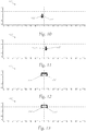
- FIG. 10 to 27 show different light distributions, with in Figures 14 and 15 Intensities of the Isolux curves are shown as examples, their intensity amounts for all Figures 10 to 27 be valid.
- an intensity maximum is in accordance with a line projection Fig. 18 with approx. 78k candela about twice as large as the intensity maximum of an area lighting of a low beam with approx. 40 k candela according to Fig. 14 . So that the driver has a contrast of a projected line versus one In front of the area lighting, that is, a switched-on low beam light function of the vehicle, can detect, such an intensity difference is necessary.
- the light intensities used by way of example can be converted into illuminance intensities, as is familiar to the person skilled in the art.
- Fig. 1 an overview of a vehicle 1 is shown, which has left and right main headlights 2 'and 2 "and auxiliary headlights 3' and 3" according to the invention.
- the two main headlights 2 ', 2 preferably produce a light distribution of low beam or high beam.
- the two additional headlights 3', 3" according to the invention produce a linear light distribution as well as a light distribution of an additional high beam in two modules, whereby all light distributions can be activated individually or in combination of the headlights , as well as the combination of left and right headlights is possible to take into account the respective driving situation.
- the position of the individual headlights 2 ', 2 ", 3' and 3" on the vehicle 1 can vary and depends, among other things, on the design of the vehicle. A position of the auxiliary headlights 2 ', 2 "according to the invention on the vehicle 1 close to the roadway can be advantageous.
- a headlight system 4 which comprises a main headlight 2 ', 2 "and an additional headlight 3', 3".
- a light image 110 ', 110 "of the auxiliary headlight 3', 3” can be superimposed by a further light image 210 ', 210 ", 220', 220" of the main headlight 2 ', 2 " left and right additional headlights 3 ', 3 "and left and right main headlights 2', 2".
- the left and right additional headlights 3 ', 3 " can each project different light images.
- the light image of the main headlight 2 ', 2 " can be a light image of a low beam 210', 210" or a high beam 220 ', 220 ".
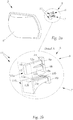
- FIG. 2a the arrangement of the additional headlights 3 ', 3 "as additional headlights 3 is shown in overview.
- the additional headlight 3 consists of a light module 5 that emits the light, forms it and projects it in front of the vehicle as a light image 110', 110" through downstream imaging optics 8.
- Detail A in Figure 2b shows the light module 5, which comprises a first light module 6 for generating first light emissions by first light sources 9a and 9b, as well as a second light module 7 for generating second light emissions by second light sources 10a, 10b, 10c and a primary optics 11.
- the primary optics 11 of the Auxiliary headlight 3 comprises two parts, a first primary lens 11a of the first light module and a second primary lens 11b of the second light module and has a plurality of light guide elements 12a, 12b, 13a, 13b, 13c, with each light guide element 12a, 12b, 13a, 13b, 13c has a light entry surface 14 for coupling in a light emission, as well as a light exit surface 15.
- the light guide elements 12a, 12b, 13a, 13b, 13c of the primary optics form two groups for two different light distributions, which are represented by the light modules 6 and 7 with the associated light sources. The structural separation of the two light modules serves to decouple the optical propagation paths.
- the first light emission couples into a first light guide element 12a, 12b of the primary optics 11 and the second light emission couples into a second light guide element 13a, 13b, 13c of the primary optics 11.
- the light sources 9a, 9b, 10a, 10b, 10c can be coupled loosely or firmly to the respective light entry surfaces.
- the type of coupling mentioned is determined, among other things, by the design of the light sources 9a, 9b, 10a, 10b, 10c, whereby a spacing between light entry surfaces and light sources can be structurally provided in order to counter mechanical loads, such as vibrations or different temperature expansions of individual components to be able to.
- Light guide elements 12a, 12b, 13a, 13b, 13c form together with a diaphragm 16, which comprises diaphragm openings 16a, 16b (not shown in this figure) the light emissions and form a luminous image on the common surface F, which is the Petzval surface of the Imaging optics 8 reshaped.
- the diaphragm 16, through its diaphragm openings 16a, 16b, usually ensures sharp contours in the luminous image, while the light guide elements 12a, 12b, 13a, 13b, 13c provide suitable flat emission characteristics.
- the cross section of the light guide elements 12a, 12b, 13a, 13b, 13c usually increases from the light entry surface 14 to the light exit surface 15. Consequently, the light exit surfaces 15 are larger than the corresponding light entry surfaces 14 of the respective light guide element 12a, 12b, 13a, 13b, 13c.
- the light exit surfaces 14 of all light guide elements 12a, 12b, 13a, 13b, 13c preferably lie in an area F. It is favorable if the area F is a plane and thus allows a particularly simple construction of the primary optics 11. In addition, it is advantageous if the light exit surfaces of all light guide elements 12a, 12b, 13a, 13b, 13c, which are assigned to the same light module 6, 7, have a common light exit surface and all light guide elements of the first light module 6, from those of the second light module 7, are structurally separated in order to reduce cross-coupling between the two light modules 6 and 7. This is very important for high efficiency of the auxiliary headlight 3, since the light emission generated should be transformed into the desired light distribution with as little loss as possible.
- the primary optics 11 can be made of an elastic (e.g. silicone, photopolymers, etc.) or solid (e.g. polycarbonate, thermoplastics, photopolymers, glass, etc.) material, the particular choice being determined by commercial requirements.
- the primary optics are particularly easy to manufacture using an injection molding process.
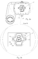
- Fig. 3a shows the additional headlight 3 with a holder 17 for mechanical fastening of the light modules 6 and 7 in the additional headlight 3, without a mounted cover and without imaging optics 8.
- B in Figure 3b is the position of the first light module 6 for generating the linear intensity maximum 8a by the associated light guide elements 12a, 12b and of the second light module 7 for generating the rectangular intensity maximum 122 ', 122 "by the associated light guide elements 13a, 13b, 13c in the light distribution.
- an axis of rotation D is shown, about which the auxiliary headlight 3 can be pivoted mechanically in order to enable the light distributions generated to be tracked following the course of the road.
- a second axis of rotation for pivoting about a further, for example horizontal, axis is not shown.
- the holder 17 is made in one piece here in order to fix the light guide elements of the primary optics 11. As a result, only a common fastening is necessary and design, manufacture, assembly, etc. are simplified.
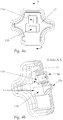
- FIGs 4a and 4b the light modules 6 and 7 or the two-part primary optics 11, which are held in position with a holder 17, are shown in each case.
- the holder can be made of an elastic or solid material, with structural reinforcements only being advantageous in the area around the light guide elements 12a, 12b, 13a, 13b, 13c and the edge area of the holder 17 in order to keep the weight of the holder 17 as low as possible .
- the light sources 9a, 9b, 10a, 10b, 10c themselves are mostly held by a circuit board (not shown).
- Fig. 5 shows the light module 6, 7 in a front view with a mounted screen 13, which has two screen openings 16a, 16b in order to shape the light emission in addition to the light guide elements 12a, 12b, 13a, 13b, 13c.
- the diaphragm 16 creates particularly sharp contours in the light distribution, which is essential, for example, for line projection and its visibility through good contrast.
- the common screen 16 allows, among other things, a cost-effective and simple design, manufacture or assembly and supports the compact and lightweight design of the auxiliary headlight.
- the cover 16 is fastened by one or more mounting points 20 in the additional headlight 3, the installation points 20 being particularly advantageously designed as bores through which screws connect the cover to another part of the additional headlight 3.
- the bracket 17 is designed in such a way that it has recesses at the positions of the screw connections in order to support a common fastening by the aforementioned screws of the cover 16 with a housing of the auxiliary headlight 3 with the bracket 17 in between, the screws forming the cover 16 connect to the housing of the auxiliary headlight 3 and a cooling device 18 can be part of the housing.
- the assembly consequently proves to be particularly simple and quick, and the number of components required for the additional headlight 3 is kept to a minimum.
- the use of four screws is advantageous, as this achieves particular stability and freedom from distortion due to mechanical or thermal loading forces. Screws as a detachable connection have particularly favorable properties with regard to maintenance. Furthermore, the structure is particularly simple if a circuit board 21 (not shown) is inserted into the combination of a cover 16, a holder 17 and a housing of the auxiliary headlight 3, which includes at least several light sources 9a, 9b, 10a, 10b, 10c and is fixed by the same fastening, wherein the circuit board 21 or the light sources 9a, 9b, 10a, 10b, 10c arranged thereon is thermally well connected to the housing.
- Fig. 6 shows the light module 6, 7 in a perspective view with the mounted screen 16 and the screen openings 16a, 16b.
- Fig. 7 shows the very compact additional headlight 3 in the front view, on which the imaging optics 8 is placed.
- the axis of rotation D can be seen, about which the auxiliary headlight 3 can be pivoted mechanically.
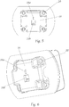
- Fig. 8 shows the auxiliary headlight 3 in a view from behind with the common cooling device 18 for the light module 6, 7 located on the rear.
- the common cooling device 18 can be small, light and designed to be inexpensive.
- the additional headlight 3 can be pivoted about the axis of rotation D.
- the common control device 19, which electrically controls the two light modules 6 and 7, is not shown.
- the common control device 19 achieves cost and weight advantages.
- Fig. 9 shows the auxiliary headlight 3 in the exploded view with imaging optics 8 and holder 17 and circuit board 21 with light sources 9a, 9b, 10a, 10b, 10c (not shown).
- the holder 17 can be made of an elastic or rigid material.
- the common holder 17 for the two-part primary optics 11 supports a simple construction or assembly, and a compact design of the additional headlight is achieved.
- the circuit board 21 can usually include further electronic circuits such as driver and logic stages for switching the light sources 9a, 9b, 10a, 10b, 10c or the control device, as well as connection units for connecting to cables for control and power supply.
- the joint design of the connection units for both light modules is advantageous in order to keep the cable harness in the vehicle simple.
- the circuit board 21 can be designed in such a way that it supports a suitable thermal connection between light sources 10 and cooling device 18, for example through openings in the circuit board 21.
- the optical radiating surface of the light source 10 is equipped with special cooling contacts in order to enable a favorable connection to a heat sink.
- the cooling by the cooling device 18 can be active, that is to say by a fan for air cooling or a liquid cooling, in the present example the cooling device 18 is a passive heat sink.
- FIGS. 10 to 27 show photos in Cartesian representation with angular scales on both axes according to the UN ECE guidelines for uniform conditions for approval of motor vehicle headlights (e.g. TRANS / WP.29 / 343), which represent isolux lines for different intensities.
- TRANS / WP.29 / 343 represent isolux lines for different intensities.
- a left main headlight is designated below with the reference number 2 'and a right main headlight is designated with the reference number 2 ", the main headlights typically having the same design, but being constructed symmetrically about the longitudinal axis of the vehicle.
- the left auxiliary headlight 3 ' which is structurally, for example, an auxiliary headlight 3 according to FIG Figures 1 to 9 can, for example, generate a light image 110 'through a first left light module 6', which structurally corresponds to the first light module 6 ( Fig. 10 ).
- the right auxiliary headlight 3 ′′ which is structurally for example an auxiliary headlight 3 according to FIG Figures 1 to 9 can generate a light image 110 ", for example, by means of a first right light module 6", which structurally corresponds to the first light module 6 ( Fig. 11 ).
- the light images 110 'and 110 " can each have line light distributions 111', 111" with linear intensity maxima 112 'and 112 ".
- the light distributions shown are partially formed by superimposing several light distributions. Consequently, for example, the intensity maxima shown are, strictly speaking, a superposition of an individual intensity maximum with a further light distribution at the location of the maximum, whereby the respective function value no longer corresponds exactly to the original intensity maximum at that location.
- this aspect is not taken into account and is not shown separately in the figures. This aspect is to be used in principle and therefore also for the light distributions in the other figures.
- the left and right main headlights 2 ', 2 include light functions for a low beam 210', 210" and a high beam 220 ', 220 ".
- Fig. 10 shows the light image 110 'of the left auxiliary headlight 3' with its first light distribution 111 'and its first, linear intensity maximum 112', ie a line light distribution.
- Fig. 11 shows the light image 110 ′′ of the right auxiliary headlight 3 ′′ with its first light distribution 111 ′′ and its first, linear intensity maximum 112 ′′, ie a line light distribution.
- Fig. 12 shows the light image 120 'of the left auxiliary headlight 3' with its second light distribution 121 'and its second, essentially rectangular intensity maximum 122', ie an additional high beam light distribution.
- the essentially rectangular intensity maximum 122 ′ can be square, rectangular, trapezoidal or else elliptical, for example, and have pointed or rounded corners. Special forms of the intensity maximum 122 'are also conceivable in order to obtain the best possible light distribution depending on the traffic situation.
- a dynamic form of the intensity maximum 122 ' which is actively adapted, for example, to the respective traffic situation, is also possible. This dynamic adaptation can mean the targeted switching off of individual areas within the intensity maximum 122 'in order to obtain a glare-free high beam and to fade out the oncoming traffic at certain points.
- Fig. 13 shows the light image 120 ′′ of the right auxiliary headlight 3 ′′ with its second light distribution 121 ′′ and its second, essentially rectangular intensity maximum 122 ′′, for example an additional high beam light distribution.
- a light image 210 'of a light distribution 211' of a low beam of the left main headlight 2 ' is shown with a typical asymmetry in the cut-off line.
- Fig. 15 shows the photo 110 'of the left auxiliary headlight 3' with the linear light distribution 111 ' Fig. 10 , which the light image 210 'the low beam light distribution 211' of the left main headlight 2 'after Fig. 14 is superimposed.
- the intensity maximum 112 ' is approximately twice as large with approx. 78 k candela as the intensity maximum with approx. 40 k candela according to a front area lighting or a low beam Fig. 14 .
- Fig. 16 shows the light image 110 "of the right auxiliary headlight 3" with the linear light distribution 111 "with the maximum intensity 112" Fig. 11 , on which the light image 210 ′′ with the low beam light distribution 211 ′′ of the right main headlight 2 ′′ is superimposed.
- Fig. 17 shows the superimposed overall light image of the light images 110 ', 110 " Figures 15 and 16 of the left and right auxiliary headlights 3 ', 3 "with linear intensity maxima 112', 112" in the respective light distribution 111 ', 111 ", as well as the light images 210', 210" of the light distributions 211 ', 211 "of the left and right main headlight 2' , 2 "each with a low beam light distribution.
- Fig. 18 simulates the overall light distribution Fig. 17 as a light image by projection onto the roadway in front of the vehicle 1. Compared to the aforementioned light images, the projection view contains perspective image distortions.
- a light image 220 ′′ of a high beam light distribution 221 ′′ of the right main headlight 2 ′′ is shown.
- Fig. 21 shows the light image 220 'with the high beam light distribution 221' of the left main headlight 2 'together with the additional high beam light distribution 121' and the maximum intensity 122 'of the left auxiliary headlight 3'.
- Fig. 22 shows the light image 220 "with the high beam light distribution 221" of the right main headlight 2 "together with the light image 120" of the additional high beam light distribution 121 “and the maximum intensity 122" of the right auxiliary headlight 3 ".
- Fig. 23 simulates a light distribution Fig. 22 as a photograph by projection onto the roadway in front of vehicle 1.
- Fig. 24 shows the light image 220 'with the high beam light distribution 221' of the left main headlight 2 'together with the light image 120' of the additional high beam light distribution 121 'and the light image 110' with the line light distribution 111 'of the left auxiliary headlight 3'.
- Fig. 25 shows the photo 220 "with the high beam light distribution 221" of the right main headlight 2 "together with the photo 120" of the additional high beam light distribution 121 “and the photo 110" with the line light distribution 111 "of the right auxiliary headlight 3".
- Fig. 26 shows an overall light image of the light images 110 ', 120', 110 “, 120” of a superimposed overall light distribution of the left and right auxiliary headlights 3 ', 3 "with linear intensity maxima 112', 112" in the respective light distribution 111 ', 111 "together with the respective Additional high beam light distribution 121 ', 121 "and the respective intensity maximum 122', 122 ', as well as the left and right main headlights 2', 2" each with a light image 220 ', 220 "which comprises a high beam light distribution 221', 221” .
Landscapes
- Engineering & Computer Science (AREA)
- General Engineering & Computer Science (AREA)
- Mechanical Engineering (AREA)
- Physics & Mathematics (AREA)
- Microelectronics & Electronic Packaging (AREA)
- Optics & Photonics (AREA)
- Lighting Device Outwards From Vehicle And Optical Signal (AREA)
- Non-Portable Lighting Devices Or Systems Thereof (AREA)
Claims (15)
- Projecteur auxiliaire (3, 3', 3") pour un véhicule, qui est agencé pour générer une image lumineuse à l'avant du véhicule (1) en émettant de la lumière à partir d'au moins un module d'éclairage (5) et pour la projeter à l'avant du véhicule à travers une optique d'imagerie (8) en aval, dans lequel
au moins un premier module d'éclairage (6) est configuré pour générer une première image lumineuse (110', 110") avec au moins une première distribution lumineuse (111', 111") avec au moins une première intensité maximale en forme de ligne, orientée essentiellement verticalement (112', 112"), et
au moins un deuxième module d'éclairage (7) est configuré pour générer une deuxième image lumineuse (120', 120") avec une deuxième distribution de lumière (121', 121") d'au moins une seconde, d'intensité maximale essentiellement rectangulaire (122', 122"), et les images lumineuses (110', 110", 120', 120") des deux modules lumineux (6, 7) sont superposés, le premier maximum d'intensité (112', 112") étant situé verticalement en dessous du deuxième maximum d'intensité (122', 122"), caractérisé en ce que
le au moins un premiermodule d'éclairage (6) pour générer une première émission de lumière par au moins une première source lumineuse (9a, 9b),
le au moins un deuxièmemodule lumineux (7) pour générer une deuxième émission de lumière par au moins une deuxième source lumineuse (10a, 10b, 10c), le projecteur auxiliaire (3, 3', 3") comprenant en outre
au moins une optique primaire (11), l'optique primaire ayant une pluralité d'éléments de guidage de la lumière (12a, 12b, 13a, 13b, 13c), chaque élément de guidage de la lumière (12a, 12b, 13a, 13b, 13c) ayant une surface d'entrée de la lumière (14) pour coupler une émission de lumière, et une surface d'émission de lumière (15)
dans laquelle la première émission de lumière se couple dans au moins un premier élément de guidage de lumière (12a, 12b) de l'optique primaire (11), la deuxième émission de lumière se couple dans au moins un deuxième élément de guidage de lumière (13a, 13b, 13c) de l'optique primaire (11)
au moins un diaphragme (16) disposé en aval de l'optique primaire (11) et comportant au moins une première ouverture de diaphragme (16a), qui est tournée vers la surface de sortie de la lumière du premier élément de guidage de la lumière (12a, 12b), et au moins une deuxième ouverture de diaphragme (16b), qui est tournée vers la surface de sortie de la lumière du deuxième élément de guidage de la lumière (13a, 13b, 13c), 13b, 13c), l'optique primaire (11) et le diaphragme (16) générant une image d'éclairage global à partir des émissions lumineuses et
une optique d'imagerie (8) en aval du diaphragme (16) projetant l'image d'éclairage global sous forme d'image lumineuse dans la direction de rayonnement du projecteur auxiliaire (3, 3', 3"). - Projecteur auxiliaire (3, 3', 3") selon la revendication 1, caractérisé en ce que les longs côtés du maximum d'intensité sensiblement rectangulaire (122', 122") sont orientés horizontalement, de préférence d La position horizontale du premier maximum d'intensité (112', 112") se situe dans la largeur horizontale du deuxième maximum d'intensité (122', 122").
- Projecteur auxiliaire (3, 3', 3") selon la revendication 1 ou 2, caractérisé en ce que la première intensité maximale (112', 112") et la deuxième intensité maximale (122', 122') sont séparées par une distance verticale.
- Projecteur auxiliaire (3, 3', 3") selon l'une quelconque des revendications 1 à 3, caractérisé en ce que les surfaces d'émission de lumière (15) de tous les éléments de guidage de la lumière (12a, 12b, 13a, 13b, 13c) se trouvent dans une surface (F), de préférence la surface (F) étant un plan.
- Projecteur auxiliaire (3, 3', 3") selon l'une quelconque des revendications 1 à 4, caractérisé en ce que les surfaces d'émission de lumière (15) de tous les éléments de guidage de la lumière (12a, 12b, 13a, 13b, 13c) appartenant au même module d'éclairage (6, 7) forment une surface commune d'émission de lumière, les éléments de guidage de la lumière (12a, 12b, 13a, 13b, 13c) du premier module d'éclairage (6) étant de préférence structurellement séparés de ceux du deuxième module d'éclairage (7), un support commun (17) étant de préférence prévu pour tous les éléments de guidage de la lumière (12a, 12b, 13a, 13b, 13c).
- Projecteur auxiliaire (3, 3', 3") selon l'une quelconque des revendications 1 à 5, caractérisé en ce que le premier module d'éclairage (6) comprend une pluralité de sources lumineuses (9a, 9b) disposées sensiblement verticalement en une rangée les unes au-dessus des autres.
- Projecteur auxiliaire (3, 3', 3") selon l'une quelconque des revendications 1 à 6, caractérisé en ce que le deuxième module d'éclairage (7) comprend une pluralité de sources lumineuses (10a, 10b, 10c) disposées sensiblement horizontalement côte à côte en une rangée, les sources lumineuses (9a, 9b, 10a, 10b, 10c) étant de préférence des LED.
- Projecteur auxiliaire (3, 3', 3") selon l'une quelconque des revendications 1 à 7, caractérisé en ce que le premier module d'éclairage (6) est disposé verticalement au-dessus du deuxième module d'éclairage (7) est organisé.
- Projecteur auxiliaire (3, 3', 3") selon l'une quelconque des revendications 1 à 8, caractérisé en ce que les ouvertures (16a, 16b) de l'ouverture (16) sont sensiblement linéaires et/ou rectangulaires.
- Projecteur auxiliaire (3, 3', 3") selon l'une quelconque des revendications 1 à 9, caractérisé en ce que le premier module d'éclairage (6) et le deuxième module d'éclairage (7) sont disposés sur un dispositif de refroidissement commun (18).
- Projecteur auxiliaire (3, 3', 3") selon l'une quelconque des revendications 1 à 10, caractérisé en ce que le premier module d'éclairage (6) et le deuxième module d'éclairage (7) sont contrôlés par un dispositif de contrôle commun (19).
- Projecteur auxiliaire (3, 3', 3") selon l'une quelconque des revendications 1 à 11, caractérisé en ce que le projecteur auxiliaire (3, 3', 3") peut pivoter autour d'au moins un axe (D).
- Système de phares (4) Système de projecteurs (4), caractérisé en ce que le système de projecteurs (4) comprend au moins un projecteur principal (2', 2") et au moins un projecteur auxiliaire (3, 3', 3") selon l'une des revendications 1 à 12, et l'image lumineuse (110', 110", 120', 120") du projecteur auxiliaire (3, 3'), 3") est superposée à au moins une autre image lumineuse (210', 210", 220', 220") du phare principal (2', 2"), dans laquelle de préférence un véhicule (1) comprend un phare auxiliaire gauche et droit (3', 3") et un phare principal gauche et droit (2', 2").
- Système de phares (4) selon la revendication 13, caractérisé en ce que les phares auxiliaires gauche et droit (3', 3") projettent respectivement des images lumineuses différentes (110', 110", 120', 120").
- Système de phare (4) selon la revendication 13 ou 14, caractérisé en ce que le motif lumineux (210', 210", 220', 220") projecteur principal (2', 2") est une répartition lumineuse d'un feu de route (221', 221") ou d'un feu de croisement (211', 211").
Applications Claiming Priority (2)
| Application Number | Priority Date | Filing Date | Title |
|---|---|---|---|
| ATA51074/2015A AT518098B1 (de) | 2015-12-17 | 2015-12-17 | Zusatzscheinwerfer für Fahrzeuge sowie Scheinwerfersystem |
| PCT/AT2016/060121 WO2017100812A1 (fr) | 2015-12-17 | 2016-12-09 | Projecteur additionnel pour véhicules |
Publications (2)
| Publication Number | Publication Date |
|---|---|
| EP3390899A1 EP3390899A1 (fr) | 2018-10-24 |
| EP3390899B1 true EP3390899B1 (fr) | 2021-03-31 |
Family
ID=57680023
Family Applications (1)
| Application Number | Title | Priority Date | Filing Date |
|---|---|---|---|
| EP16819419.9A Active EP3390899B1 (fr) | 2015-12-17 | 2016-12-09 | Projecteur additionnel pour véhicules |
Country Status (6)
| Country | Link |
|---|---|
| US (1) | US10632901B2 (fr) |
| EP (1) | EP3390899B1 (fr) |
| JP (1) | JP6526340B2 (fr) |
| CN (1) | CN108368986B (fr) |
| AT (1) | AT518098B1 (fr) |
| WO (1) | WO2017100812A1 (fr) |
Families Citing this family (15)
| Publication number | Priority date | Publication date | Assignee | Title |
|---|---|---|---|---|
| DE102016109147A1 (de) * | 2016-05-18 | 2017-11-23 | Hella Kgaa Hueck & Co. | Scheinwerfermodul mit einer Abblendlichtfunktion und mit einer Fernlichtfunktion auf Basis von Leuchtdioden |
| US10816156B2 (en) * | 2017-02-14 | 2020-10-27 | Everlight Electronics Co., Ltd. | Light guiding element, light guiding device, and lighting module |
| EP3677829B1 (fr) * | 2017-10-10 | 2023-08-09 | Great Wall Motor Company Limited | Lentille primaire, ensemble électroluminescent, système électroluminescent et phare |
| FR3073925B1 (fr) * | 2017-11-20 | 2020-11-13 | Valeo Vision | Element optique pour module optique de vehicule automobile |
| CN110736070B (zh) * | 2018-07-19 | 2021-09-10 | 嘉兴海拉灯具有限公司 | 一种车灯模组及一种车灯 |
| US12613018B2 (en) * | 2019-02-21 | 2026-04-28 | HELLA GmbH & Co. KGaA | Lighting device, in particular lighting device for a vehicle |
| CN110030532B (zh) * | 2019-05-14 | 2023-10-20 | 华域视觉科技(上海)有限公司 | 一种照明系统及车辆 |
| WO2021104626A1 (fr) * | 2019-11-28 | 2021-06-03 | HELLA GmbH & Co. KGaA | Dispositif d'éclairage de véhicule à moteur |
| EP4162194B1 (fr) * | 2020-06-03 | 2025-09-10 | HELLA GmbH & Co. KGaA | Phare de véhicule |
| FR3121498B1 (fr) * | 2021-04-01 | 2023-08-04 | Valeo Vision | Module optique d’un système lumineux d’un véhicule automobile |
| DE102021116230A1 (de) | 2021-06-23 | 2022-12-29 | HELLA GmbH & Co. KGaA | Verfahren zur Projektion einer Führungslinie auf eine Fahrbahn |
| EP4191127B1 (fr) * | 2021-12-02 | 2025-01-29 | ZKW Group GmbH | Dispositif d'éclairage pour phare de motocyclette |
| EP4197859B1 (fr) * | 2021-12-17 | 2024-08-28 | ZKW Group GmbH | Optique primaire avec guides de lumiere pour phare de motocyclette |
| KR20240045842A (ko) * | 2022-09-30 | 2024-04-08 | 현대모비스 주식회사 | 차량용 램프 및 그 램프를 포함하는 차량 |
| EP4462014A1 (fr) * | 2023-05-12 | 2024-11-13 | ZKW Group GmbH | Dispositif d'éclairage pour un phare de véhicule automobile et phare de véhicule automobile |
Family Cites Families (24)
| Publication number | Priority date | Publication date | Assignee | Title |
|---|---|---|---|---|
| US20060023461A1 (en) * | 2002-01-14 | 2006-02-02 | Richard Knight | Vehicular dynamic angle adjusted lighting |
| JP4535965B2 (ja) * | 2005-08-16 | 2010-09-01 | 株式会社小糸製作所 | 車両用灯具 |
| US20110096562A1 (en) * | 2008-03-26 | 2011-04-28 | Lambert Chad D | Fog Lamp and the Like Employing Semiconductor Light Sources |
| US8475019B2 (en) * | 2008-05-01 | 2013-07-02 | Magna International Inc. | Hotspot cutoff D-optic |
| DE102008048764A1 (de) | 2008-09-24 | 2010-03-25 | Hella Kgaa Hueck & Co. | Beleuchtungsvorrichtung für Kraftfahrzeuge |
| DE102009009472B4 (de) | 2009-02-19 | 2021-12-30 | Volkswagen Aktiengesellschaft | Verfahren zum Unterstützen eines Fahrers eines Fahrzeugs und Fahrerassistenzsystem für ein Fahrzeug |
| DE102011118274B4 (de) * | 2010-12-03 | 2022-03-24 | Docter Optics Se | Scheinwerferlinse für einen Fahrzeugscheinwerfer |
| JP5659835B2 (ja) * | 2011-02-08 | 2015-01-28 | スタンレー電気株式会社 | 車両用灯具 |
| DE102011077636A1 (de) * | 2011-04-27 | 2011-11-03 | Automotive Lighting Reutlingen Gmbh | Lichtmodul eines Kraftfahrzeugs zur Erzeugung einer Spotverteilung einer Fernlicht-Lichtverteilung und Kraftfahrzeugscheinwerfer mit einem solchen Modul |
| JP5719697B2 (ja) * | 2011-06-10 | 2015-05-20 | 株式会社小糸製作所 | 車両の前照灯装置 |
| AT511761B1 (de) * | 2011-08-08 | 2014-02-15 | Zizala Lichtsysteme Gmbh | Led-lichtquellenmodul für einen fahrzeugscheinwerfer sowie fahrzeugscheinwerfer und fahrzeugscheinwerfersystem |
| EP3056803B1 (fr) * | 2011-09-01 | 2018-06-06 | Koito Manufacturing Co., Ltd. | Appareil de phare automobile |
| AT512246B1 (de) * | 2011-11-22 | 2014-02-15 | Zizala Lichtsysteme Gmbh | Led-projektionsmodul und scheinwerfer mit modul |
| US9033562B2 (en) * | 2011-12-27 | 2015-05-19 | Ichikoh Industries, Ltd. | Vehicle headlamp |
| AT512865B1 (de) * | 2012-05-09 | 2014-12-15 | Zizala Lichtsysteme Gmbh | Beleuchtungseinrichtung für einen Kraftfahrzeugscheinwerfer sowie Lichtmodul und Kraftfahrzeugscheinwerfer mit Beleuchtungseinrichtung |
| AT512864B1 (de) * | 2012-05-09 | 2014-12-15 | Zizala Lichtsysteme Gmbh | Beleuchtungsvorrichtung zur Erzeugung einer segmentierten Lichtverteilung sowie Kraftfahrzeugscheinwerfer und Scheinwerfersystem |
| DE102012220457B4 (de) * | 2012-11-09 | 2023-05-25 | Plastic Omnium Lighting Systems Gmbh | Beleuchtungseinrichtung |
| DE102013200442B3 (de) * | 2013-01-15 | 2014-02-13 | Automotive Lighting Reutlingen Gmbh | Lichtmodul für einen Kraftfahrzeugscheinwerfer, der zur Erzeugung streifenförmiger Lichtverteilungen eingerichtet ist |
| FR3006421B1 (fr) * | 2013-05-30 | 2017-08-11 | Valeo Vision | Module d'eclairage pour projecteur de vehicule automobile, projecteur equipe de tels modules, et ensemble de projecteurs |
| AT514967B1 (de) * | 2013-10-25 | 2015-08-15 | Zizala Lichtsysteme Gmbh | Mikroprojektions-Lichtmodul für einen Kraftfahrzeugscheinwerfer |
| DE102014203313A1 (de) * | 2014-02-25 | 2015-08-27 | Volkswagen Aktiengesellschaft | Leuchteinrichtung für ein Kraftfahrzeug |
| EP3434517B1 (fr) | 2014-03-03 | 2023-04-05 | Koito Manufacturing Co., Ltd. | Phare de véhicule et système de commande de phare de véhicule |
| JP2015149307A (ja) * | 2015-05-25 | 2015-08-20 | 株式会社小糸製作所 | 発光モジュールおよび車両用灯具 |
| JP6796764B2 (ja) * | 2016-09-13 | 2020-12-09 | パナソニックIpマネジメント株式会社 | 実装基台、発光装置、移動体用照明装置及び移動体 |
-
2015
- 2015-12-17 AT ATA51074/2015A patent/AT518098B1/de not_active IP Right Cessation
-
2016
- 2016-12-09 JP JP2018531410A patent/JP6526340B2/ja active Active
- 2016-12-09 CN CN201680074155.7A patent/CN108368986B/zh active Active
- 2016-12-09 EP EP16819419.9A patent/EP3390899B1/fr active Active
- 2016-12-09 US US16/061,816 patent/US10632901B2/en active Active
- 2016-12-09 WO PCT/AT2016/060121 patent/WO2017100812A1/fr not_active Ceased
Also Published As
| Publication number | Publication date |
|---|---|
| CN108368986B (zh) | 2020-10-16 |
| AT518098A1 (de) | 2017-07-15 |
| US10632901B2 (en) | 2020-04-28 |
| JP6526340B2 (ja) | 2019-06-05 |
| WO2017100812A1 (fr) | 2017-06-22 |
| CN108368986A (zh) | 2018-08-03 |
| JP2018537356A (ja) | 2018-12-20 |
| AT518098B1 (de) | 2017-11-15 |
| EP3390899A1 (fr) | 2018-10-24 |
| US20180370419A1 (en) | 2018-12-27 |
Similar Documents
| Publication | Publication Date | Title |
|---|---|---|
| EP3390899B1 (fr) | Projecteur additionnel pour véhicules | |
| AT518090B1 (de) | Scheinwerfer für ein Fahrzeug | |
| DE102017129254B4 (de) | Fahrzeugscheinwerfer | |
| DE102008036194B4 (de) | Lichtmodul für eine Beleuchtungseinrichtung für ein Kraftfahrzeug | |
| EP2366939B1 (fr) | Phare de véhicule automobile doté d'une source lumineuse et d'au moins deux éléments optiques répartissant la lumière | |
| EP3330597A1 (fr) | Optique primaire, optique secondaire, module, dispositif, phares de véhicule automobile et système de phares | |
| DE102010009640A1 (de) | Frontscheinwerfer mit einem LED-Reflexionssystem mit Nebellicht- und Tagfahrlichtfunktion | |
| EP2431657A2 (fr) | Module de réflecteur d'un phare de véhicule automobile | |
| DE102012211613A1 (de) | Lichtmodul | |
| DE102016221918A1 (de) | Beleuchtungsvorrichtung, insbesondere für ein Kraftfahrzeug | |
| DE112019000016B4 (de) | Automatisch geregelter Kraftfahrzeugscheinwerfer, Verfahren zur automatischen Regelung, und Kraftfahrzeug | |
| DE102017216731A1 (de) | Lampe für Fahrzeug | |
| DE102011083025A1 (de) | Beleuchtungseinrichtung für ein Fahrzeug | |
| EP3543593A1 (fr) | Dispositif d'éclairage pour un phare de véhicule automobile | |
| DE202017004932U1 (de) | Lampe für Fahrzeug | |
| DE202017001946U1 (de) | Scheinwerfer mit einem optischen System mit statischem Matrix-Abbiegelicht | |
| DE102014203313A1 (de) | Leuchteinrichtung für ein Kraftfahrzeug | |
| DE202023102261U1 (de) | Fahrzeugleuchte | |
| EP4527691A1 (fr) | Module d'éclairage pour véhicule | |
| EP2112978B1 (fr) | Phare de véhicule automobile | |
| DE102015219211A1 (de) | Lichtmodul für eine Kfz-Beleuchtungseinrichtung | |
| DE102016124863A1 (de) | System, Verfahren, Computerprogrammprodukt und computerlesbares Medium zur Lichtformung für eine Fahrzeugaußenleuchte | |
| DE102020115411A1 (de) | Beleuchtungsvorrichtung eines autonomen fahrzeugs | |
| DE102017206274A1 (de) | Verfahren zur Erzeugung einer Gesamtlichtverteilung eines Kraftfahrzeugs sowie Fernlichtmodul, Scheinwerfer und Kraftfahrzeug zur Durchführung des Verfahrens | |
| DE102012215124A1 (de) | Beleuchtungseinrichtung mit Lichtquelle, Lichtleitkörper und Reflektor |
Legal Events
| Date | Code | Title | Description |
|---|---|---|---|
| STAA | Information on the status of an ep patent application or granted ep patent |
Free format text: STATUS: UNKNOWN |
|
| STAA | Information on the status of an ep patent application or granted ep patent |
Free format text: STATUS: THE INTERNATIONAL PUBLICATION HAS BEEN MADE |
|
| PUAI | Public reference made under article 153(3) epc to a published international application that has entered the european phase |
Free format text: ORIGINAL CODE: 0009012 |
|
| STAA | Information on the status of an ep patent application or granted ep patent |
Free format text: STATUS: REQUEST FOR EXAMINATION WAS MADE |
|
| 17P | Request for examination filed |
Effective date: 20180525 |
|
| AK | Designated contracting states |
Kind code of ref document: A1 Designated state(s): AL AT BE BG CH CY CZ DE DK EE ES FI FR GB GR HR HU IE IS IT LI LT LU LV MC MK MT NL NO PL PT RO RS SE SI SK SM TR |
|
| AX | Request for extension of the european patent |
Extension state: BA ME |
|
| DAV | Request for validation of the european patent (deleted) | ||
| DAX | Request for extension of the european patent (deleted) | ||
| REG | Reference to a national code |
Ref country code: DE Ref legal event code: R079 Ref document number: 502016012729 Country of ref document: DE Free format text: PREVIOUS MAIN CLASS: F21S0008100000 Ipc: F21S0041240000 |
|
| RIC1 | Information provided on ipc code assigned before grant |
Ipc: F21S 41/143 20180101ALN20201207BHEP Ipc: F21S 41/663 20180101ALI20201207BHEP Ipc: F21Y 105/12 20160101ALN20201207BHEP Ipc: F21S 41/29 20180101ALI20201207BHEP Ipc: F21S 41/153 20180101ALN20201207BHEP Ipc: F21S 41/24 20180101AFI20201207BHEP Ipc: F21S 41/255 20180101ALN20201207BHEP Ipc: F21Y 103/10 20160101ALN20201207BHEP |
|
| GRAP | Despatch of communication of intention to grant a patent |
Free format text: ORIGINAL CODE: EPIDOSNIGR1 |
|
| STAA | Information on the status of an ep patent application or granted ep patent |
Free format text: STATUS: GRANT OF PATENT IS INTENDED |
|
| INTG | Intention to grant announced |
Effective date: 20210122 |
|
| GRAS | Grant fee paid |
Free format text: ORIGINAL CODE: EPIDOSNIGR3 |
|
| GRAA | (expected) grant |
Free format text: ORIGINAL CODE: 0009210 |
|
| STAA | Information on the status of an ep patent application or granted ep patent |
Free format text: STATUS: THE PATENT HAS BEEN GRANTED |
|
| AK | Designated contracting states |
Kind code of ref document: B1 Designated state(s): AL AT BE BG CH CY CZ DE DK EE ES FI FR GB GR HR HU IE IS IT LI LT LU LV MC MK MT NL NO PL PT RO RS SE SI SK SM TR |
|
| REG | Reference to a national code |
Ref country code: GB Ref legal event code: FG4D Free format text: NOT ENGLISH Ref country code: CH Ref legal event code: EP |
|
| REG | Reference to a national code |
Ref country code: AT Ref legal event code: REF Ref document number: 1377328 Country of ref document: AT Kind code of ref document: T Effective date: 20210415 |
|
| REG | Reference to a national code |
Ref country code: DE Ref legal event code: R096 Ref document number: 502016012729 Country of ref document: DE |
|
| REG | Reference to a national code |
Ref country code: IE Ref legal event code: FG4D Free format text: LANGUAGE OF EP DOCUMENT: GERMAN |
|
| REG | Reference to a national code |
Ref country code: LT Ref legal event code: MG9D |
|
| PG25 | Lapsed in a contracting state [announced via postgrant information from national office to epo] |
Ref country code: BG Free format text: LAPSE BECAUSE OF FAILURE TO SUBMIT A TRANSLATION OF THE DESCRIPTION OR TO PAY THE FEE WITHIN THE PRESCRIBED TIME-LIMIT Effective date: 20210630 Ref country code: NO Free format text: LAPSE BECAUSE OF FAILURE TO SUBMIT A TRANSLATION OF THE DESCRIPTION OR TO PAY THE FEE WITHIN THE PRESCRIBED TIME-LIMIT Effective date: 20210630 Ref country code: HR Free format text: LAPSE BECAUSE OF FAILURE TO SUBMIT A TRANSLATION OF THE DESCRIPTION OR TO PAY THE FEE WITHIN THE PRESCRIBED TIME-LIMIT Effective date: 20210331 Ref country code: FI Free format text: LAPSE BECAUSE OF FAILURE TO SUBMIT A TRANSLATION OF THE DESCRIPTION OR TO PAY THE FEE WITHIN THE PRESCRIBED TIME-LIMIT Effective date: 20210331 |
|
| PG25 | Lapsed in a contracting state [announced via postgrant information from national office to epo] |
Ref country code: SE Free format text: LAPSE BECAUSE OF FAILURE TO SUBMIT A TRANSLATION OF THE DESCRIPTION OR TO PAY THE FEE WITHIN THE PRESCRIBED TIME-LIMIT Effective date: 20210331 Ref country code: LV Free format text: LAPSE BECAUSE OF FAILURE TO SUBMIT A TRANSLATION OF THE DESCRIPTION OR TO PAY THE FEE WITHIN THE PRESCRIBED TIME-LIMIT Effective date: 20210331 Ref country code: RS Free format text: LAPSE BECAUSE OF FAILURE TO SUBMIT A TRANSLATION OF THE DESCRIPTION OR TO PAY THE FEE WITHIN THE PRESCRIBED TIME-LIMIT Effective date: 20210331 |
|
| REG | Reference to a national code |
Ref country code: NL Ref legal event code: MP Effective date: 20210331 |
|
| PG25 | Lapsed in a contracting state [announced via postgrant information from national office to epo] |
Ref country code: SM Free format text: LAPSE BECAUSE OF FAILURE TO SUBMIT A TRANSLATION OF THE DESCRIPTION OR TO PAY THE FEE WITHIN THE PRESCRIBED TIME-LIMIT Effective date: 20210331 Ref country code: NL Free format text: LAPSE BECAUSE OF FAILURE TO SUBMIT A TRANSLATION OF THE DESCRIPTION OR TO PAY THE FEE WITHIN THE PRESCRIBED TIME-LIMIT Effective date: 20210331 Ref country code: LT Free format text: LAPSE BECAUSE OF FAILURE TO SUBMIT A TRANSLATION OF THE DESCRIPTION OR TO PAY THE FEE WITHIN THE PRESCRIBED TIME-LIMIT Effective date: 20210331 Ref country code: CZ Free format text: LAPSE BECAUSE OF FAILURE TO SUBMIT A TRANSLATION OF THE DESCRIPTION OR TO PAY THE FEE WITHIN THE PRESCRIBED TIME-LIMIT Effective date: 20210331 Ref country code: EE Free format text: LAPSE BECAUSE OF FAILURE TO SUBMIT A TRANSLATION OF THE DESCRIPTION OR TO PAY THE FEE WITHIN THE PRESCRIBED TIME-LIMIT Effective date: 20210331 |
|
| PG25 | Lapsed in a contracting state [announced via postgrant information from national office to epo] |
Ref country code: SK Free format text: LAPSE BECAUSE OF FAILURE TO SUBMIT A TRANSLATION OF THE DESCRIPTION OR TO PAY THE FEE WITHIN THE PRESCRIBED TIME-LIMIT Effective date: 20210331 Ref country code: RO Free format text: LAPSE BECAUSE OF FAILURE TO SUBMIT A TRANSLATION OF THE DESCRIPTION OR TO PAY THE FEE WITHIN THE PRESCRIBED TIME-LIMIT Effective date: 20210331 Ref country code: PT Free format text: LAPSE BECAUSE OF FAILURE TO SUBMIT A TRANSLATION OF THE DESCRIPTION OR TO PAY THE FEE WITHIN THE PRESCRIBED TIME-LIMIT Effective date: 20210802 Ref country code: PL Free format text: LAPSE BECAUSE OF FAILURE TO SUBMIT A TRANSLATION OF THE DESCRIPTION OR TO PAY THE FEE WITHIN THE PRESCRIBED TIME-LIMIT Effective date: 20210331 Ref country code: IS Free format text: LAPSE BECAUSE OF FAILURE TO SUBMIT A TRANSLATION OF THE DESCRIPTION OR TO PAY THE FEE WITHIN THE PRESCRIBED TIME-LIMIT Effective date: 20210731 |
|
| REG | Reference to a national code |
Ref country code: DE Ref legal event code: R097 Ref document number: 502016012729 Country of ref document: DE |
|
| PG25 | Lapsed in a contracting state [announced via postgrant information from national office to epo] |
Ref country code: AL Free format text: LAPSE BECAUSE OF FAILURE TO SUBMIT A TRANSLATION OF THE DESCRIPTION OR TO PAY THE FEE WITHIN THE PRESCRIBED TIME-LIMIT Effective date: 20210331 Ref country code: DK Free format text: LAPSE BECAUSE OF FAILURE TO SUBMIT A TRANSLATION OF THE DESCRIPTION OR TO PAY THE FEE WITHIN THE PRESCRIBED TIME-LIMIT Effective date: 20210331 Ref country code: ES Free format text: LAPSE BECAUSE OF FAILURE TO SUBMIT A TRANSLATION OF THE DESCRIPTION OR TO PAY THE FEE WITHIN THE PRESCRIBED TIME-LIMIT Effective date: 20210331 |
|
| PLBE | No opposition filed within time limit |
Free format text: ORIGINAL CODE: 0009261 |
|
| STAA | Information on the status of an ep patent application or granted ep patent |
Free format text: STATUS: NO OPPOSITION FILED WITHIN TIME LIMIT |
|
| 26N | No opposition filed |
Effective date: 20220104 |
|
| PG25 | Lapsed in a contracting state [announced via postgrant information from national office to epo] |
Ref country code: IS Free format text: LAPSE BECAUSE OF FAILURE TO SUBMIT A TRANSLATION OF THE DESCRIPTION OR TO PAY THE FEE WITHIN THE PRESCRIBED TIME-LIMIT Effective date: 20210731 |
|
| PG25 | Lapsed in a contracting state [announced via postgrant information from national office to epo] |
Ref country code: MC Free format text: LAPSE BECAUSE OF FAILURE TO SUBMIT A TRANSLATION OF THE DESCRIPTION OR TO PAY THE FEE WITHIN THE PRESCRIBED TIME-LIMIT Effective date: 20210331 Ref country code: IT Free format text: LAPSE BECAUSE OF FAILURE TO SUBMIT A TRANSLATION OF THE DESCRIPTION OR TO PAY THE FEE WITHIN THE PRESCRIBED TIME-LIMIT Effective date: 20210331 |
|
| REG | Reference to a national code |
Ref country code: CH Ref legal event code: PL |
|
| REG | Reference to a national code |
Ref country code: BE Ref legal event code: MM Effective date: 20211231 |
|
| PG25 | Lapsed in a contracting state [announced via postgrant information from national office to epo] |
Ref country code: LU Free format text: LAPSE BECAUSE OF NON-PAYMENT OF DUE FEES Effective date: 20211209 Ref country code: IE Free format text: LAPSE BECAUSE OF NON-PAYMENT OF DUE FEES Effective date: 20211209 |
|
| PG25 | Lapsed in a contracting state [announced via postgrant information from national office to epo] |
Ref country code: BE Free format text: LAPSE BECAUSE OF NON-PAYMENT OF DUE FEES Effective date: 20211231 |
|
| PG25 | Lapsed in a contracting state [announced via postgrant information from national office to epo] |
Ref country code: LI Free format text: LAPSE BECAUSE OF NON-PAYMENT OF DUE FEES Effective date: 20211231 Ref country code: CH Free format text: LAPSE BECAUSE OF NON-PAYMENT OF DUE FEES Effective date: 20211231 |
|
| REG | Reference to a national code |
Ref country code: AT Ref legal event code: MM01 Ref document number: 1377328 Country of ref document: AT Kind code of ref document: T Effective date: 20211209 |
|
| PG25 | Lapsed in a contracting state [announced via postgrant information from national office to epo] |
Ref country code: AT Free format text: LAPSE BECAUSE OF NON-PAYMENT OF DUE FEES Effective date: 20211209 |
|
| PG25 | Lapsed in a contracting state [announced via postgrant information from national office to epo] |
Ref country code: HU Free format text: LAPSE BECAUSE OF FAILURE TO SUBMIT A TRANSLATION OF THE DESCRIPTION OR TO PAY THE FEE WITHIN THE PRESCRIBED TIME-LIMIT; INVALID AB INITIO Effective date: 20161209 |
|
| PG25 | Lapsed in a contracting state [announced via postgrant information from national office to epo] |
Ref country code: CY Free format text: LAPSE BECAUSE OF FAILURE TO SUBMIT A TRANSLATION OF THE DESCRIPTION OR TO PAY THE FEE WITHIN THE PRESCRIBED TIME-LIMIT Effective date: 20210331 |
|
| P01 | Opt-out of the competence of the unified patent court (upc) registered |
Effective date: 20230528 |
|
| PG25 | Lapsed in a contracting state [announced via postgrant information from national office to epo] |
Ref country code: GR Free format text: LAPSE BECAUSE OF FAILURE TO SUBMIT A TRANSLATION OF THE DESCRIPTION OR TO PAY THE FEE WITHIN THE PRESCRIBED TIME-LIMIT Effective date: 20210331 |
|
| PG25 | Lapsed in a contracting state [announced via postgrant information from national office to epo] |
Ref country code: MK Free format text: LAPSE BECAUSE OF FAILURE TO SUBMIT A TRANSLATION OF THE DESCRIPTION OR TO PAY THE FEE WITHIN THE PRESCRIBED TIME-LIMIT Effective date: 20210331 |
|
| PG25 | Lapsed in a contracting state [announced via postgrant information from national office to epo] |
Ref country code: TR Free format text: LAPSE BECAUSE OF FAILURE TO SUBMIT A TRANSLATION OF THE DESCRIPTION OR TO PAY THE FEE WITHIN THE PRESCRIBED TIME-LIMIT Effective date: 20210331 |
|
| PG25 | Lapsed in a contracting state [announced via postgrant information from national office to epo] |
Ref country code: MT Free format text: LAPSE BECAUSE OF FAILURE TO SUBMIT A TRANSLATION OF THE DESCRIPTION OR TO PAY THE FEE WITHIN THE PRESCRIBED TIME-LIMIT Effective date: 20210331 |
|
| REG | Reference to a national code |
Ref country code: DE Ref legal event code: R084 Ref document number: 502016012729 Country of ref document: DE |
|
| PGFP | Annual fee paid to national office [announced via postgrant information from national office to epo] |
Ref country code: GB Payment date: 20251218 Year of fee payment: 10 |
|
| PGFP | Annual fee paid to national office [announced via postgrant information from national office to epo] |
Ref country code: FR Payment date: 20251218 Year of fee payment: 10 |
|
| PGFP | Annual fee paid to national office [announced via postgrant information from national office to epo] |
Ref country code: DE Payment date: 20251222 Year of fee payment: 10 |