EP3392094A1 - Dispositif de blocage et déblocage d'un composant essentiel au fonctionnement d'un véhicule automobile - Google Patents
Dispositif de blocage et déblocage d'un composant essentiel au fonctionnement d'un véhicule automobile Download PDFInfo
- Publication number
- EP3392094A1 EP3392094A1 EP18167160.3A EP18167160A EP3392094A1 EP 3392094 A1 EP3392094 A1 EP 3392094A1 EP 18167160 A EP18167160 A EP 18167160A EP 3392094 A1 EP3392094 A1 EP 3392094A1
- Authority
- EP
- European Patent Office
- Prior art keywords
- locking
- locking pin
- unlocking
- guide
- slide element
- Prior art date
- Legal status (The legal status is an assumption and is not a legal conclusion. Google has not performed a legal analysis and makes no representation as to the accuracy of the status listed.)
- Granted
Links
Images

Classifications
-
- B—PERFORMING OPERATIONS; TRANSPORTING
- B60—VEHICLES IN GENERAL
- B60R—VEHICLES, VEHICLE FITTINGS, OR VEHICLE PARTS, NOT OTHERWISE PROVIDED FOR
- B60R25/00—Fittings or systems for preventing or indicating unauthorised use or theft of vehicles
- B60R25/01—Fittings or systems for preventing or indicating unauthorised use or theft of vehicles operating on vehicle systems or fittings, e.g. on doors, seats or windscreens
- B60R25/02—Fittings or systems for preventing or indicating unauthorised use or theft of vehicles operating on vehicle systems or fittings, e.g. on doors, seats or windscreens operating on the steering mechanism
-
- B—PERFORMING OPERATIONS; TRANSPORTING
- B60—VEHICLES IN GENERAL
- B60R—VEHICLES, VEHICLE FITTINGS, OR VEHICLE PARTS, NOT OTHERWISE PROVIDED FOR
- B60R25/00—Fittings or systems for preventing or indicating unauthorised use or theft of vehicles
- B60R25/01—Fittings or systems for preventing or indicating unauthorised use or theft of vehicles operating on vehicle systems or fittings, e.g. on doors, seats or windscreens
- B60R25/02—Fittings or systems for preventing or indicating unauthorised use or theft of vehicles operating on vehicle systems or fittings, e.g. on doors, seats or windscreens operating on the steering mechanism
- B60R25/021—Fittings or systems for preventing or indicating unauthorised use or theft of vehicles operating on vehicle systems or fittings, e.g. on doors, seats or windscreens operating on the steering mechanism restraining movement of the steering column or steering wheel hub, e.g. restraining means controlled by ignition switch
- B60R25/0215—Fittings or systems for preventing or indicating unauthorised use or theft of vehicles operating on vehicle systems or fittings, e.g. on doors, seats or windscreens operating on the steering mechanism restraining movement of the steering column or steering wheel hub, e.g. restraining means controlled by ignition switch using electric means, e.g. electric motors or solenoids
- B60R25/02153—Fittings or systems for preventing or indicating unauthorised use or theft of vehicles operating on vehicle systems or fittings, e.g. on doors, seats or windscreens operating on the steering mechanism restraining movement of the steering column or steering wheel hub, e.g. restraining means controlled by ignition switch using electric means, e.g. electric motors or solenoids comprising a locking member radially and linearly moved towards the steering column
-
- B—PERFORMING OPERATIONS; TRANSPORTING
- B60—VEHICLES IN GENERAL
- B60R—VEHICLES, VEHICLE FITTINGS, OR VEHICLE PARTS, NOT OTHERWISE PROVIDED FOR
- B60R25/00—Fittings or systems for preventing or indicating unauthorised use or theft of vehicles
- B60R25/01—Fittings or systems for preventing or indicating unauthorised use or theft of vehicles operating on vehicle systems or fittings, e.g. on doors, seats or windscreens
- B60R25/02—Fittings or systems for preventing or indicating unauthorised use or theft of vehicles operating on vehicle systems or fittings, e.g. on doors, seats or windscreens operating on the steering mechanism
- B60R25/021—Fittings or systems for preventing or indicating unauthorised use or theft of vehicles operating on vehicle systems or fittings, e.g. on doors, seats or windscreens operating on the steering mechanism restraining movement of the steering column or steering wheel hub, e.g. restraining means controlled by ignition switch
Definitions
- the invention relates to a device for locking and releasing a functionally essential component of a motor vehicle, for example.
- Devices for locking and releasing functionally essential components in motor vehicles are basically known and are used, for example, for locking steering columns or gear shift levers.
- Such devices usually have a movably mounted locking pin, which is transferred by means of a transmission between a locking position for locking the functionally essential component and an unlocking position for unlocking the functionally essential component.
- the transmission becomes Driving a slider element used, which carries a signal generator and is used to detect at least one position of the locking pin.
- the transmission has to drive the slider element basically a trained as a positive guide link plate, in which a guide pin of the slider element is forcibly guided.
- a steering column or a gear shift lever which is simple in structure, which is easy to assemble, which is reliable and safe in operation and the one reliable detection of at least one position of the locking pin allows.
- the present object is achieved by a device having the features of the independent device claim, in particular from the characterizing part. Furthermore, the object of the invention by a method for driving a device for locking and releasing a functionally essential component of a motor vehicle having the features of the independent method claim, in particular from the characterizing part proposed.
- a device having the features of the independent device claim in particular from the characterizing part.
- preferred developments of the invention are listed.
- Features that are disclosed for the individual embodiments of the locking device according to the invention and the method according to the invention can be combined with each other in such a way that with respect to the disclosure of the embodiments of the device according to the invention and the method according to the invention is always mutually referenced or can be.
- the invention provides a device for locking and releasing a functionally essential component of a motor vehicle, in particular a steering column or a gearshift lever, having a between a locking position for locking the functionally essential component and an unlocking position for unlocking the functionally essential component movably mounted locking pin, a transmission, which with the locking pin in mechanical operative connection to transfer the locking pin between the locking position and the unlocking position, and a detection unit having a slider element for moving a signal generator and at least a first stationary sensor element for detecting at least one position of the slide element, wherein the slide element with the transmission is in mechanical operative connection to the slider element between a rest position, in which the signal transmitter spaced from the first Sensorelem ent, and to transfer a detection position in which the signal generator is located in the detection area of the first sensor element.
- the detection unit has a spring element in order to act on the slide element with a spring force from the rest position into the detection position.
- a device for locking and releasing a functionally essential component of a motor vehicle in particular a steering column or a gearshift lever
- the slider element carries a signal generator, for example a magnet, which is displaceable back and forth with the slider element.
- the signal generator may, for example, have a south pole with two adjacent north poles.
- the detection by means of associated sensor elements makes it possible to determine the position of the slider element and thus indirectly also the position of the locking pin.
- Another functionality of the slider element is a mechanical engagement of the slider element in a corresponding recess on the locking pin in its unlocked position.
- the transmission may have a partially formed as a positive guide guide slot to move the slider between the rest position and the detection position for engagement with the locking pin.
- a spring element is provided in order to act on the slide element with a spring force from the rest position into the detection position to ensure that the slide element reliably reaches the detection position.
- the spring element ensures that the slider element nevertheless reaches its detection position.
- Mechanical protection of the locking pin in the unlocking advantageously serves to ensure that the locking pin is reliably maintained at a distance from the functionally essential component and thereby releases the functionally essential component for operating the motor vehicle.
- the unlocking position of the locking pin is to be reliably detected, so that the electronics of the motor vehicle is driven accordingly during operation of the motor vehicle and not accidentally fails.
- the idea of the invention lies in providing a double protection during the transfer of the slide element from the rest position into the detection position. If the transmission with the slider element interact mechanically error-free, so the spring element is a redundant measure. However, should the slide element lose the mechanical connection to the transmission, so the spring element ensures that the slide element reaches its detection position despite mechanical interruptions in the drive chain safely. Back to the rest position, the slider element can then not be pushed out by the transmission, but possibly by the locking pin against the action of the spring force.
- the slide element is mounted in a translatory manner, preferably along a direction which extends substantially transversely to a stroke direction of the locking bolt, movable.
- the slider element can be stably driven. Transverse to the stroke direction of the locking bolt, a reliable locking of the locking pin can be achieved in the unlocked position.
- the corresponding positions of the locking pin and the corresponding positions of the slide element can be easily matched.
- the invention can provide that the transmission may have a drive wheel, for example in the form of a worm wheel, to pick up a drive action from a, preferably electric, drive and to provide it to the locking bolt and / or the sliding element.
- the transmission may be formed in the context of the invention as a worm gear.
- Such a transmission is advantageously low noise, has a high load capacity, allows high ratios between a worm and a drive wheel and may also be self-locking.
- a small drive can be sufficient to allow a stable driving of the locking pin and / or the slider element.
- both the locking pin in its end positions, as well as the slider element can be reliably held in its end positions without the risk to leave the respective end position and / or end position unintentionally.
- the slide element is in the rest position spaced from the locking pin and that the slide element in the detection position, the locking pin positively and / or non-positively locked when the locking pin is in the unlocked position.
- the functionality of the slider element can be extended.
- the slider element can be used not only for detecting the unlocking position of the locking pin, but also act as a securing or locking element.
- the slider element may have a locking portion which can engage in the detection position of the slider element in a corresponding recess on the locking pin, which may face the locking portion in the unlocked position of the locking pin.
- the signal generator can have at least one permanent magnet with a magnetic orientation, preferably three permanent magnets with alternating magnetic orientations.
- a permanent magnet can generate an electromagnetic signal without the need for an energy source to generate the signal.
- An electromagnetic signal is advantageously suitable for precise position determination of the slide element.
- the first sensor element may have at least one, preferably two, magnetic field sensors, preferably Hall sensors, in order to detect the signal generator in the detection region of the first sensor element.
- the first sensor element may comprise a magnetic field sensor, for example in the form of a Hall sensor with a 3D triggering. Such a sensor element is very precise.
- the first sensor element may comprise two magnetic field sensors, for example in the form of one-dimensional Hall sensors. Such sensors are cost-effective components that allow a precise detection in interaction. By using two magnetic field sensors can also be achieved the advantage that despite a failure of one of the magnetic field sensors, a measurement by the other sensor is still possible.
- the detection unit has at least one second stationary sensor element for detecting at least one can have further position of the slide element, wherein the slide element can be located in the detection position of the second sensor element, in particular in the rest position, wherein the second sensor element preferably at least one magnetic field sensor, preferably a Hall sensor, may have.
- the second sensor element preferably at least one magnetic field sensor, preferably a Hall sensor.
- the transmission has a, preferably rotatable about an axis of rotation of the transmission driven, switching element having a, preferably helical cam, which cooperates with a corresponding control means of the locking pin to a rotational movement of the switching element in a translatory To transform movement of the locking pin along a stroke direction between the locking position and the unlocking position.
- the switching element can be rotatably connected to a drive wheel of the transmission and rotate with the drive wheel.
- the control cam of the switching element may extend helically or helically around the axis of rotation of the drive wheel, which displaces the control means of the locking pin over the height of the control cam along a stroke direction of the locking pin up and down when turning the switching element.
- the length of the control cam can be greater than a stroke, which performs the locking pin between the locking position and the unlocking position. Consequently, the drive effect can be stably transmitted to the locking pin via the control cam.
- the transmission has a, preferably curved or spiral, in particular rotatably driven about a rotational axis of the transmission, guide slot, which cooperates with a corresponding guide pin of the slider element to a rotational movement of the guide link in a translational movement the slider element between the rest position and the detection position, preferably along a direction that is in Substantially transversely to a stroke direction of the locking pin extends to transform.
- the guide slot can be formed on a disk-shaped element, which is non-rotatably connected to a drive wheel of the transmission, or formed directly on one side of the drive wheel and extend substantially helically around the axis of rotation.
- the guide pin of the slide element can be guided, wherein in the inner of the guide slot close to the axis of rotation of the drive wheel, the slider element comes close to the locking pin and with a growing distance from the axis of rotation, the slide element away from the locking pin.
- the length of the guide slot can be greater than a transfer path of the slide element between the detection position and the rest position. About the shape and the length of the guide slot can be made a stable transmission of the drive effect on the slide element.
- the guide slot with a growing distance to a rotation axis of the transmission first by a guide slot on both sides closed guide area, then opening to one side of the guide slot and in particular wider inlet area and then a along the Guide slot radially one-sided open support area for the guide pin of the slide element has.
- the guide pin In the interior of the guide slot, the guide pin can be reliably guided by the guide area of the guide slot closed on both sides or forcibly guided.
- the inlet area can advantageously serve as a transition area between the guide area and the support area of the guide slot which is open radially on one side. During a movement of the guide pins in the guide slot from the inside to the outside, the guide pin can be supported on one side of the support area.
- the entry area can serve to capture the guide pin and to transfer in the closed on both sides guide area.
- a larger transfer path can be provided by moving the slide member via a rotation of the guide link than in a completely closed guide slot, since the full radius of a drive wheel for the transfer path of the slide element can be utilized.
- the guide slot in particular on a broadening entry region, can have a catch rib pointing in a radial direction away from a rotation axis of the gear mechanism in order to transfer a guide pin of the slide element from a support region open radially along one side of the guide slot supporting the guide slot on both sides closed guide area, wherein the catching rib can preferably survive in a radial direction away from a rotational axis of the transmission over the diameter of a drive wheel of the transmission.
- the guide pin of the slide element can be reliably intercepted during movement in the guide slot from outside to inside and be transferred to the closed on both sides guide region of the guide slots.
- the guide pin of the slide element at least one catch nose, preferably two unwound catch lugs, which projects radially or preferably in opposite directions from the guide pin and the transfer of the guide pins of the slide element from one along the Supporting guide radially supporting one side open support area in a along the guide slot closed on both sides or forcibly guided guide area or support.
- the catch nose or catch noses can or may come to bear resiliently on a catch rib of the guide slot to allow a smooth, jerk-free movement of the guide pins of the slide element along the guide slot.
- the invention can provide that the transmission is a flow for the slider element relative to the locking pin when leaving a position (or a wake for the locking pin against the slider element when leaving a Position) and a wake for the slider element relative to the locking pin upon reaching a position (or a lead for the locking pin upon reaching a position), wherein the transmission may in particular have a control cam for driving the locking pin and a guide slot for driving the slider element, wherein the path of a control means of the locking pin on the control cam may be preferably shorter than the path of a guide pin of the slider element on the guide slot.
- the guide pin of the slider element passes through a longer path than the control means of the locking pin.
- the transfer path of the slide element between the detection position and the rest position is greater than the stroke of the locking pin between the unlocked position and the locking position.
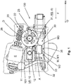
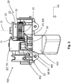
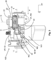
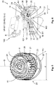
- FIGS. 1 to 3 show a device 100 for locking and releasing a functionally essential component of a motor vehicle, in particular a steering column or a gearshift lever, one between a locking position VP (s FIG. 3 ) for locking the functionally essential component and an unlocking position EP (see FIG. 2 ) for unlocking the functionally essential component movably mounted locking pin 10.
- the device 100 comprises a gear 20 which is in mechanical operative connection with the locking pin 10 in order to drive the locking pin 10 between the locking position VP and the unlocking position EP.
- the locking pin 10 is mounted longitudinally displaceable along a stroke direction H in a guide housing 101.
- the device 100 comprises a detection unit 30, which has a slide element 31 for moving a signal transmitter 32 and at least one first stationary sensor element 33 for detecting at least one position RS, DS of the slide element 31.
- the slide member 31 is in mechanical operative connection with the gear 20, to the slider member 31 between a rest position RS, in which the signal transmitter 32 is spaced from the first sensor element 33, and a detection position DS, in which the signal generator 32 in the detection region of the first sensor element 33 is to convict.
- the detection unit 30 has a spring element 34 in order to act on the slide element 31 with a spring force F from the rest position RS into the detection position DS.
- the detection unit 30 provides two functionalities by means of a preferably longitudinally displaceable slide element 31.
- the detection unit 30 serves to detect the position of the locking bolt 10 Slider element 31, the signal generator 32 with at least one permanent magnet M, which is displaceable with the slide member 31 back and forth between the detection position DS and the rest position RS.
- the signal generator 32 can also have three permanent magnets M1, M2, M3 with alternating magnetic orientations, so that the detection region of the at least one first sensor element 33 or a second sensor element 35 faces a south pole with two adjacent north poles.
- the magnetic field lines can be precisely aligned so that an electromagnetic signal with high resolution is generated.
- the transmission 20 has a guide slot 24, which is designed in part as a positive guide, in order to displace the slide element 31 between the rest position RS and the detection position DS.
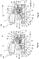
- the structure of the guide slot 24 will be described below using the FIGS. 4a to 4d and the FIG. 6 explained in detail.
- the spring element 34 generates a spring force F on the slide element 31, which loads the slide element 31 from the rest position RS into the detection position DS.
- the spring force F of the spring element 34 serves to ensure that the slide element 31 reliably reaches the detection position DS and does not unintentionally remain in an intermediate position.
- the spring force F of the spring element 34 is used even in situations in which the slide element 31 loses the operative connection to the transmission 20 or to the guide slot 24, for example if an associated guide pin 36 of the slide element 31 breaks off, the slider element 31 still has its detection position DS reached.
- the unlocking position EP of the locking bolt 10 is reliably detected and, on the other hand, the locking bolt 10 is mechanically locked in its unlocking position EP.
- the spring-loaded slider element according to the invention 31 provides a mechanical protection of the locking pin 10 in the unlocking position EP, so that the locking pin 10 is reliably maintained at a distance from the functionally essential component and not blocked during operation of the motor vehicle, the functionally essential component unintentionally. Reliable detection of Release position EP of the locking pin 10 ensures that the electronics of the motor vehicle is driven accordingly during operation of the motor vehicle and not accidentally fails.
- the detection unit 30 thus provides a double protection in the transfer of the slide member 31 from the rest position RS in the detection position DS.
- the spring member 34 only supports the driving action of the transmission 20.
- the spring member 34 takes over the role of the transmission 20 to the Slide element 31 despite a lack of mechanical intervention with the transmission 20 from the rest position RS to the detection position DS to convict.
- the slider element 31 can then not be pushed out by the gear 20 or the spring element 34, but possibly by the locking pin 10 against the action of the spring force F.
- a device 100 for locking and releasing a functionally essential component of a motor vehicle for example.
- a steering column or a gearshift lever is provided, which is simply constructed with only a few components that is easy to assemble, which is reliable and safe in operation and the one reliable detection of at least one unlocking position EP of the locking pin 10 allows.
- the spring load is also ensured that the locking pin 10 is reliably achieved in the unlocked position EP by the spring-loaded slide element 31 according to the invention and the sensor detects the associated unlocking position EP of the locking pin 10 in a secure manner.
- the transmission 20 a drive wheel 21 in the form of a worm wheel, which is in engagement with a worm 26.
- the worm 26 is rotatably driven by an electric drive or motor E about a drive shaft.
- the drive wheel 21 is rotatably moved about an output shaft in motion, which is hereinafter referred to as a rotation axis D of the transmission 20.
- the transmission 20 can thus be designed as a worm gear.
- the drive wheel 21 transmits the driving action of the electric drive E to a switching element 22 for the locking pin 10 and the guide slot 24 for the Sliding element 31.
- Such a transmission 20 is advantageously low noise, resilient and allows high ratios between the worm 26 and the drive wheel 21.
- a relatively small electric motor E allow a stable power transmission to the locking pin 10 and the slider element 31.
- a transmission 20 may also be self-locking.
- the locking pin 10 can be reliably secured in its end positions VP, EP and the slide member 31 in its end positions RS, DS against accidental displacement.
- Other forms of transmission instead of a worm gear but can also be conceivable within the scope of the invention, which can be driven via the drive shaft, but not via the output shaft.
- the slider element 31 is translationally, preferably along a direction Q, which extends substantially transverse to the stroke direction H of the locking pin 10, movable.
- a translational mounting and movement of the slide element 31 can be carried out stably.
- Transverse to the stroke direction H of the locking bolt 10 a reliable locking of the locking bolt 10 can be achieved in the unlocked position EP by the slide member 31 in the detection position DS.
- the translational movement of the locking pin 10 along the stroke direction H and the translational movement of the slider element 31 transversely to the stroke direction H can be easily coordinated.
- the slider element 31 is in the rest position RS of FIG. 4d spaced from the locking pin 10 and in the detection position DS of FIG. 4a in mechanical engagement with the locking pin 10 when the locking pin 10 is in the unlocking position EP.
- the slide member 31 can lock the locking pin 10 in the unlocked position EP in the detection position DS.
- the slide member 31 has a locking portion A, which engages in the detection position DS of the slide member 31 in a corresponding recess 12 on the locking pin 10, which is opposite to the locking portion A in the unlocking position EP of the locking pin 10.
- the signal transmitter 32 of the detection unit 30, which is movable with the slide element 31, has at least one permanent magnet M with a magnetic orientation, preferably three permanent magnets M1, M2, M3 with alternating magnetic orientations.
- the permanent magnets M, M1, M2, M3 can generate an electromagnetic signal without the need for an energy source.
- an electromagnetic signal with a high resolution can be provided which even with the aid of favorable, for example one-dimensional, magnetic field sensors precisely can be recognized.
- the first sensor element 33 can have at least one, preferably two, magnetic field sensors, preferably Hall sensors, in order to detect the signal generator 32 in the detection region of the first sensor element 33.
- the first sensor element 33 may have only one magnetic field sensor, for example in the form of a Hall sensor with a 3D triggering. Such a sensor element 33 is very precise.
- the first sensor element 33 can have two magnetic field sensors, for example, in the form of low-cost one-dimensional Hall sensors, which enable a precise position detection in interaction.
- the advantage can be achieved that the detection is possible despite a failure of one of the magnetic field sensors.
- the detection unit 30 can have at least one second stationary sensor element 35 for detecting the rest position RS of the slide element 31.
- the second sensor element 35 can also have at least one magnetic field sensor, preferably a Hall sensor.
- an active, albeit indirect detection of not only the unlocking position EP, but also the locking position VP of the locking pin 10 can be made possible.
- the monitoring and detection of both end positions VP, EP of the locking pin 10 has the advantage that the position detection of the locking pin 10 can be made more precise and reliable than when monitoring only one position EP, because there are more data available for evaluation, compared with each other and thus verified can be.
- the gear 20 has a rotatable about the rotational axis D of the transmission 20 driven switching element 22 with a helical cam 23 in which a corresponding control means 11 of the locking pin 10 is guided to a rotational movement of the switching element 22 in a translational movement of the locking pin 10th along the stroke direction H between the locking position VP and the unlocking position EP to transform.
- the switching element 22 is rotatably connected to the drive wheel 21 of the transmission 20, as it is in the FIG. 5 is shown.
- the control cam 23 of the switching element 22 turns substantially helically or helically around the axis of rotation D of the drive wheel 21 so that upon rotation of the switching element 22, the control means 11 of the locking pin 10 over the height of the control cam 23 either displaced upwards or downwards, whereby the Locking pin 10 is transferred to the unlocking position EP or in the locking position VP.
- the length of the control cam 23 is greater than the stroke that the locking pin 10 executes between the locking position VP and the unlocking position EP. Consequently, the drive effect can be stably transmitted to the locking pin 10 via the control cam 23.
- the transmission 20 has a curved, substantially helical guide slot 24 which is rotatably driven about the axis of rotation D of the transmission 20.
- the guide slot 24 of the corresponding guide pin 36 of the slide member 31 is guided to a rotational movement of the guide slot 24 in a translational movement of the slide member 31 between the rest position RS and the detection position DS along a direction Q, which is substantially transverse to the stroke direction H of the locking pin 10 extends to transform.
- the guide slot 24 may be formed on a disk-shaped element, which may be non-rotatably connected to the drive wheel 21 of the transmission 20, or directly on one side of the drive wheel 21, which faces away from the switching element 22.
- the guide slot 24 extends substantially helically about the axis of rotation D of the drive wheel 21 in a plane which is aligned perpendicular to the axis of rotation D of the drive wheel 21.
- the guide slot 24 of the guide pin 36 of the slide member 31 is guided, wherein in the inner of the guide slot 24 close to the axis of rotation D of the drive wheel 21, the slide member 31 comes close to the locking pin 10 and with a growing distance r from the axis of rotation D, the slide member 31 from Locking pin 10 removed.
- the length of the guide slot 24 is greater than a transfer path of the slide element 31 between the detection position DS and the rest position RS.
- About the shape and length of the guide slot 24 is advantageously a stable transmission of the drive effect of the electric drive E allows the slide member 31.
- FIG. 5 shows further that the guide slot 24 with a growing distance r to the axis of rotation D of the transmission 20 first along the guide slot 24 on both sides closed or positively guided guide area I, then opening to one side of the guide slot 24 and in particular wider inlet area II and thereafter a support region III for the guide pin 36 of the slide element 31 which is open radially on one side along the guide slot 24.
- the guide pin 36 of the slide element 31 can be reliably guided by the guide area I of the guide slot 24 closed or positively guided on both sides.
- the entry area II serves as a transition area between the guide area I and the support area III of the guide slot 24 which is open radially on one side.
- the guide pin 36 When the guide slide 36 moves in the guide slot 24 from the inside to the outside, the guide pin 36 can be supported on one side of the support area III.
- the support region III which is open radially on one side, a larger transfer path can be provided by moving the slide member 31 over a guide slide 24, as the full radius of the drive wheel 21 for the transfer path of the slide element 31 between the detection position DS and the rest position RS can be exploited.
- the guide slot 24 in the context of the invention, in particular at the widening entry area II, in a radial direction R away from the axis of rotation D of the gear 20 facing catch rib 25 to the transfer of the guide pin 36 of the slide member 31 from along support the guide slot 24 radially on one side open support area III in the along the guide slot 24 closed on both sides or positively guided guide portion I, wherein the capture rib 25 preferably in a radial direction R away from the axis of rotation D of the transmission 20 seen over the diameter d of the drive wheel 21st of the transmission 20 can survive.
- the full radius of the drive wheel 21 can be exploited to provide an extended transfer path of the slide element 31 between the rest position RS and the detection position DS, in particular compared to a fully closed or fully guided guide slot 24.
- the guide pin 36 of the slider element 31 at least one catch nose N1, preferably two unwound catch noses N1, N2, which radially, preferably in opposite directions, projecting from the guide pin 36 and the transfer of the guide pins 36 of the slide element 31st from a supported along the guide slot 24 radially on one side support area III in a along the guide slot 24 on both sides closed or positively guided guide area I supports or support.
- a mechanical interaction between the inlet region II of the guide slot 24, in particular the catch rib 25 of the guide slot 24, and the guide pin 36 of the slide element 31 can be facilitated.
- the catch nose N1 or catch noses N1, N2 can or can come to bear resiliently on a catch rib 25 of the guide slot 24 to allow jerk-free movement of the guide pin 36 of the slide member 31 along the guide slot 24.
- the path of the control means 11 of the locking bolt 10 via the control cam 23 is substantially shorter than the path of the guide pin 36 of the slide member 31 via the guide slot 24.
- a flow for the slide member 31 against the locking pin 10th when leaving the respective position RS, DS or a caster for the locking pin 10 relative to the slide member 31 when leaving the respective position VP, EP are provided.
- a wake for the slide member 31 relative to the locking pin 10 upon reaching the respective position RS, DS or a flow for the locking pin 10 upon reaching the respective position VP, EP can be provided.
- the locking pin 10 always reaches the respective position VP, EP first, before the slide element 31 is transferred into the respective position RS, DS after the locking pin 10.
Landscapes
- Engineering & Computer Science (AREA)
- Mechanical Engineering (AREA)
- Lock And Its Accessories (AREA)
Applications Claiming Priority (1)
| Application Number | Priority Date | Filing Date | Title |
|---|---|---|---|
| DE102017108247.6A DE102017108247A1 (de) | 2017-04-19 | 2017-04-19 | Vorrichtung zum Sperren und Freigeben eines funktionswesentlichen Bauteils eines Kraftfahrzeuges |
Publications (2)
| Publication Number | Publication Date |
|---|---|
| EP3392094A1 true EP3392094A1 (fr) | 2018-10-24 |
| EP3392094B1 EP3392094B1 (fr) | 2021-06-09 |
Family
ID=61972418
Family Applications (1)
| Application Number | Title | Priority Date | Filing Date |
|---|---|---|---|
| EP18167160.3A Active EP3392094B1 (fr) | 2017-04-19 | 2018-04-13 | Dispositif de blocage et déblocage d'un composant essentiel au fonctionnement d'un véhicule automobile |
Country Status (3)
| Country | Link |
|---|---|
| EP (1) | EP3392094B1 (fr) |
| CN (1) | CN108749763B (fr) |
| DE (1) | DE102017108247A1 (fr) |
Cited By (1)
| Publication number | Priority date | Publication date | Assignee | Title |
|---|---|---|---|---|
| CN117001649A (zh) * | 2023-07-21 | 2023-11-07 | 吉林大学 | 一种带有双稳态锁止机构的电动人工肌肉作动器 |
Citations (6)
| Publication number | Priority date | Publication date | Assignee | Title |
|---|---|---|---|---|
| EP1176065A2 (fr) * | 2000-07-19 | 2002-01-30 | Marquardt GmbH | Mécanisme de verrouillage, notamment pour une vehicule à moteur |
| EP1232921A1 (fr) * | 2001-01-24 | 2002-08-21 | Valeo Sicherheitssysteme GmbH | Système de verouillage |
| WO2004098960A1 (fr) * | 2003-05-06 | 2004-11-18 | Huf Hülsbeck & Fürst GmbH & Co KG | Dispositif pour verrouiller la colonne de direction d'un vehicule a moteur |
| WO2004098959A1 (fr) * | 2003-05-06 | 2004-11-18 | Huf Hülsbeck & Fürst GmbH & Co KG | Dispositif pour verrouiller la colonne de direction d'un vehicule a moteur |
| WO2009074543A1 (fr) * | 2007-12-10 | 2009-06-18 | Huf Hülsbeck & Fürst Gmbh & Co. Kg | Dispositif de commande d'un organe de verrouillage |
| EP2572945A1 (fr) * | 2011-09-20 | 2013-03-27 | Huf Hülsbeck & Fürst GmbH & Co. KG | Verrouillage de direction électrique |
-
2017
- 2017-04-19 DE DE102017108247.6A patent/DE102017108247A1/de not_active Withdrawn
-
2018
- 2018-04-04 CN CN201810301479.0A patent/CN108749763B/zh active Active
- 2018-04-13 EP EP18167160.3A patent/EP3392094B1/fr active Active
Patent Citations (6)
| Publication number | Priority date | Publication date | Assignee | Title |
|---|---|---|---|---|
| EP1176065A2 (fr) * | 2000-07-19 | 2002-01-30 | Marquardt GmbH | Mécanisme de verrouillage, notamment pour une vehicule à moteur |
| EP1232921A1 (fr) * | 2001-01-24 | 2002-08-21 | Valeo Sicherheitssysteme GmbH | Système de verouillage |
| WO2004098960A1 (fr) * | 2003-05-06 | 2004-11-18 | Huf Hülsbeck & Fürst GmbH & Co KG | Dispositif pour verrouiller la colonne de direction d'un vehicule a moteur |
| WO2004098959A1 (fr) * | 2003-05-06 | 2004-11-18 | Huf Hülsbeck & Fürst GmbH & Co KG | Dispositif pour verrouiller la colonne de direction d'un vehicule a moteur |
| WO2009074543A1 (fr) * | 2007-12-10 | 2009-06-18 | Huf Hülsbeck & Fürst Gmbh & Co. Kg | Dispositif de commande d'un organe de verrouillage |
| EP2572945A1 (fr) * | 2011-09-20 | 2013-03-27 | Huf Hülsbeck & Fürst GmbH & Co. KG | Verrouillage de direction électrique |
Cited By (1)
| Publication number | Priority date | Publication date | Assignee | Title |
|---|---|---|---|---|
| CN117001649A (zh) * | 2023-07-21 | 2023-11-07 | 吉林大学 | 一种带有双稳态锁止机构的电动人工肌肉作动器 |
Also Published As
| Publication number | Publication date |
|---|---|
| DE102017108247A1 (de) | 2018-10-25 |
| CN108749763A (zh) | 2018-11-06 |
| EP3392094B1 (fr) | 2021-06-09 |
| CN108749763B (zh) | 2022-11-08 |
Similar Documents
| Publication | Publication Date | Title |
|---|---|---|
| EP3617428B1 (fr) | Fermeture pour deux-roues | |
| EP2473690B1 (fr) | Dispositif de verrouillage | |
| WO2012089405A1 (fr) | Procédé et dispositif destinés à fournir une information de déplacement, notamment pour détecter le blocage d'un système de fermeture | |
| EP3617431A1 (fr) | Serrure | |
| DE102008031217A1 (de) | Sperrvorrichtung mit einem Sperrglied zur Sperrung eines funktionswesentlichen Bauteils | |
| EP3208159B1 (fr) | Dispositif destiné à déplacer un élément de blocage | |
| EP3392094B1 (fr) | Dispositif de blocage et déblocage d'un composant essentiel au fonctionnement d'un véhicule automobile | |
| EP3392095B1 (fr) | Dispositif de blocage et déblocage d'un composant essentiel au fonctionnement d'un véhicule automobile | |
| EP4264089B1 (fr) | Actionneur, et dispositif de mise en prise d'un verrou de stationnement d'une transmission automatique de véhicule automobile comportant ledit actionneur, et véhicule automobile équipé de celui-ci | |
| DE102004030362B4 (de) | Vorrichtung zum gesteuerten Arretieren einer sicherheitsrelevanten Einrichtung, wie beispielweise einer Schutztür oder dergleichen | |
| DE102016108565A1 (de) | Umsetzungselement für eine elektrische Lenkradsperre | |
| EP3992038B1 (fr) | Dispositif de blocage et déblocage d'un composant essentiel au fonctionnement d'un véhicule automobile | |
| DE102014017828A1 (de) | Lenkungsverriegelungsvorrichtung für ein Fahrzeug | |
| EP3243713A1 (fr) | Levier de capteur pour un dispositif de détection d'au moins une position de réglage d'un antivol de direction | |
| DE102008058650B4 (de) | Drehstellungssensorsystem | |
| DE102016103873A1 (de) | Verriegelungsvorrichtung | |
| DE102013018836A1 (de) | Mechanische Sperrvorrichtung, insbesondere für den Fahrzeugbereich | |
| WO2016058717A1 (fr) | Dispositif d'actionnement d'un dispositif de blocage | |
| EP2094540B1 (fr) | Dispositif de commande d'un organe de verrouillage | |
| EP2117887B1 (fr) | Dispositif d'asservissement d'un organe de blocage | |
| EP3312369A1 (fr) | Élément de verrouillage d'un immeuble ainsi que procédé correspondant | |
| DE102010048684A1 (de) | Elektrisch verriegelbare Fahrzeuglenkung | |
| DE102014115673A1 (de) | Antriebsvorrichtung und Antriebsverfahren | |
| DE102013103047A1 (de) | Kupplungsvorrichtung |
Legal Events
| Date | Code | Title | Description |
|---|---|---|---|
| PUAI | Public reference made under article 153(3) epc to a published international application that has entered the european phase |
Free format text: ORIGINAL CODE: 0009012 |
|
| STAA | Information on the status of an ep patent application or granted ep patent |
Free format text: STATUS: THE APPLICATION HAS BEEN PUBLISHED |
|
| AK | Designated contracting states |
Kind code of ref document: A1 Designated state(s): AL AT BE BG CH CY CZ DE DK EE ES FI FR GB GR HR HU IE IS IT LI LT LU LV MC MK MT NL NO PL PT RO RS SE SI SK SM TR |
|
| AX | Request for extension of the european patent |
Extension state: BA ME |
|
| STAA | Information on the status of an ep patent application or granted ep patent |
Free format text: STATUS: REQUEST FOR EXAMINATION WAS MADE |
|
| 17P | Request for examination filed |
Effective date: 20190424 |
|
| RBV | Designated contracting states (corrected) |
Designated state(s): AL AT BE BG CH CY CZ DE DK EE ES FI FR GB GR HR HU IE IS IT LI LT LU LV MC MK MT NL NO PL PT RO RS SE SI SK SM TR |
|
| STAA | Information on the status of an ep patent application or granted ep patent |
Free format text: STATUS: EXAMINATION IS IN PROGRESS |
|
| 17Q | First examination report despatched |
Effective date: 20191011 |
|
| GRAP | Despatch of communication of intention to grant a patent |
Free format text: ORIGINAL CODE: EPIDOSNIGR1 |
|
| STAA | Information on the status of an ep patent application or granted ep patent |
Free format text: STATUS: GRANT OF PATENT IS INTENDED |
|
| INTG | Intention to grant announced |
Effective date: 20201118 |
|
| GRAS | Grant fee paid |
Free format text: ORIGINAL CODE: EPIDOSNIGR3 |
|
| GRAA | (expected) grant |
Free format text: ORIGINAL CODE: 0009210 |
|
| STAA | Information on the status of an ep patent application or granted ep patent |
Free format text: STATUS: THE PATENT HAS BEEN GRANTED |
|
| AK | Designated contracting states |
Kind code of ref document: B1 Designated state(s): AL AT BE BG CH CY CZ DE DK EE ES FI FR GB GR HR HU IE IS IT LI LT LU LV MC MK MT NL NO PL PT RO RS SE SI SK SM TR |
|
| REG | Reference to a national code |
Ref country code: GB Ref legal event code: FG4D Free format text: NOT ENGLISH |
|
| REG | Reference to a national code |
Ref country code: CH Ref legal event code: EP Ref country code: AT Ref legal event code: REF Ref document number: 1400217 Country of ref document: AT Kind code of ref document: T Effective date: 20210615 |
|
| REG | Reference to a national code |
Ref country code: DE Ref legal event code: R096 Ref document number: 502018005582 Country of ref document: DE |
|
| REG | Reference to a national code |
Ref country code: IE Ref legal event code: FG4D Free format text: LANGUAGE OF EP DOCUMENT: GERMAN |
|
| REG | Reference to a national code |
Ref country code: LT Ref legal event code: MG9D |
|
| PG25 | Lapsed in a contracting state [announced via postgrant information from national office to epo] |
Ref country code: HR Free format text: LAPSE BECAUSE OF FAILURE TO SUBMIT A TRANSLATION OF THE DESCRIPTION OR TO PAY THE FEE WITHIN THE PRESCRIBED TIME-LIMIT Effective date: 20210609 Ref country code: LT Free format text: LAPSE BECAUSE OF FAILURE TO SUBMIT A TRANSLATION OF THE DESCRIPTION OR TO PAY THE FEE WITHIN THE PRESCRIBED TIME-LIMIT Effective date: 20210609 Ref country code: FI Free format text: LAPSE BECAUSE OF FAILURE TO SUBMIT A TRANSLATION OF THE DESCRIPTION OR TO PAY THE FEE WITHIN THE PRESCRIBED TIME-LIMIT Effective date: 20210609 Ref country code: BG Free format text: LAPSE BECAUSE OF FAILURE TO SUBMIT A TRANSLATION OF THE DESCRIPTION OR TO PAY THE FEE WITHIN THE PRESCRIBED TIME-LIMIT Effective date: 20210909 |
|
| REG | Reference to a national code |
Ref country code: NL Ref legal event code: MP Effective date: 20210609 |
|
| PG25 | Lapsed in a contracting state [announced via postgrant information from national office to epo] |
Ref country code: GR Free format text: LAPSE BECAUSE OF FAILURE TO SUBMIT A TRANSLATION OF THE DESCRIPTION OR TO PAY THE FEE WITHIN THE PRESCRIBED TIME-LIMIT Effective date: 20210910 Ref country code: RS Free format text: LAPSE BECAUSE OF FAILURE TO SUBMIT A TRANSLATION OF THE DESCRIPTION OR TO PAY THE FEE WITHIN THE PRESCRIBED TIME-LIMIT Effective date: 20210609 Ref country code: SE Free format text: LAPSE BECAUSE OF FAILURE TO SUBMIT A TRANSLATION OF THE DESCRIPTION OR TO PAY THE FEE WITHIN THE PRESCRIBED TIME-LIMIT Effective date: 20210609 Ref country code: NO Free format text: LAPSE BECAUSE OF FAILURE TO SUBMIT A TRANSLATION OF THE DESCRIPTION OR TO PAY THE FEE WITHIN THE PRESCRIBED TIME-LIMIT Effective date: 20210909 Ref country code: LV Free format text: LAPSE BECAUSE OF FAILURE TO SUBMIT A TRANSLATION OF THE DESCRIPTION OR TO PAY THE FEE WITHIN THE PRESCRIBED TIME-LIMIT Effective date: 20210609 |
|
| PG25 | Lapsed in a contracting state [announced via postgrant information from national office to epo] |
Ref country code: ES Free format text: LAPSE BECAUSE OF FAILURE TO SUBMIT A TRANSLATION OF THE DESCRIPTION OR TO PAY THE FEE WITHIN THE PRESCRIBED TIME-LIMIT Effective date: 20210609 Ref country code: EE Free format text: LAPSE BECAUSE OF FAILURE TO SUBMIT A TRANSLATION OF THE DESCRIPTION OR TO PAY THE FEE WITHIN THE PRESCRIBED TIME-LIMIT Effective date: 20210609 Ref country code: SM Free format text: LAPSE BECAUSE OF FAILURE TO SUBMIT A TRANSLATION OF THE DESCRIPTION OR TO PAY THE FEE WITHIN THE PRESCRIBED TIME-LIMIT Effective date: 20210609 Ref country code: SK Free format text: LAPSE BECAUSE OF FAILURE TO SUBMIT A TRANSLATION OF THE DESCRIPTION OR TO PAY THE FEE WITHIN THE PRESCRIBED TIME-LIMIT Effective date: 20210609 Ref country code: NL Free format text: LAPSE BECAUSE OF FAILURE TO SUBMIT A TRANSLATION OF THE DESCRIPTION OR TO PAY THE FEE WITHIN THE PRESCRIBED TIME-LIMIT Effective date: 20210609 Ref country code: RO Free format text: LAPSE BECAUSE OF FAILURE TO SUBMIT A TRANSLATION OF THE DESCRIPTION OR TO PAY THE FEE WITHIN THE PRESCRIBED TIME-LIMIT Effective date: 20210609 Ref country code: PT Free format text: LAPSE BECAUSE OF FAILURE TO SUBMIT A TRANSLATION OF THE DESCRIPTION OR TO PAY THE FEE WITHIN THE PRESCRIBED TIME-LIMIT Effective date: 20211011 Ref country code: CZ Free format text: LAPSE BECAUSE OF FAILURE TO SUBMIT A TRANSLATION OF THE DESCRIPTION OR TO PAY THE FEE WITHIN THE PRESCRIBED TIME-LIMIT Effective date: 20210609 |
|
| PG25 | Lapsed in a contracting state [announced via postgrant information from national office to epo] |
Ref country code: PL Free format text: LAPSE BECAUSE OF FAILURE TO SUBMIT A TRANSLATION OF THE DESCRIPTION OR TO PAY THE FEE WITHIN THE PRESCRIBED TIME-LIMIT Effective date: 20210609 |
|
| REG | Reference to a national code |
Ref country code: DE Ref legal event code: R097 Ref document number: 502018005582 Country of ref document: DE |
|
| PLBE | No opposition filed within time limit |
Free format text: ORIGINAL CODE: 0009261 |
|
| STAA | Information on the status of an ep patent application or granted ep patent |
Free format text: STATUS: NO OPPOSITION FILED WITHIN TIME LIMIT |
|
| PG25 | Lapsed in a contracting state [announced via postgrant information from national office to epo] |
Ref country code: DK Free format text: LAPSE BECAUSE OF FAILURE TO SUBMIT A TRANSLATION OF THE DESCRIPTION OR TO PAY THE FEE WITHIN THE PRESCRIBED TIME-LIMIT Effective date: 20210609 |
|
| 26N | No opposition filed |
Effective date: 20220310 |
|
| PG25 | Lapsed in a contracting state [announced via postgrant information from national office to epo] |
Ref country code: AL Free format text: LAPSE BECAUSE OF FAILURE TO SUBMIT A TRANSLATION OF THE DESCRIPTION OR TO PAY THE FEE WITHIN THE PRESCRIBED TIME-LIMIT Effective date: 20210609 |
|
| PG25 | Lapsed in a contracting state [announced via postgrant information from national office to epo] |
Ref country code: IT Free format text: LAPSE BECAUSE OF FAILURE TO SUBMIT A TRANSLATION OF THE DESCRIPTION OR TO PAY THE FEE WITHIN THE PRESCRIBED TIME-LIMIT Effective date: 20210609 |
|
| REG | Reference to a national code |
Ref country code: DE Ref legal event code: R082 Ref document number: 502018005582 Country of ref document: DE Representative=s name: BALS & VOGEL PATENTANWAELTE PARTG MBB, DE |
|
| REG | Reference to a national code |
Ref country code: CH Ref legal event code: PL |
|
| GBPC | Gb: european patent ceased through non-payment of renewal fee |
Effective date: 20220413 |
|
| REG | Reference to a national code |
Ref country code: BE Ref legal event code: MM Effective date: 20220430 |
|
| PG25 | Lapsed in a contracting state [announced via postgrant information from national office to epo] |
Ref country code: MC Free format text: LAPSE BECAUSE OF FAILURE TO SUBMIT A TRANSLATION OF THE DESCRIPTION OR TO PAY THE FEE WITHIN THE PRESCRIBED TIME-LIMIT Effective date: 20210609 Ref country code: LU Free format text: LAPSE BECAUSE OF NON-PAYMENT OF DUE FEES Effective date: 20220413 Ref country code: LI Free format text: LAPSE BECAUSE OF NON-PAYMENT OF DUE FEES Effective date: 20220430 Ref country code: GB Free format text: LAPSE BECAUSE OF NON-PAYMENT OF DUE FEES Effective date: 20220413 Ref country code: FR Free format text: LAPSE BECAUSE OF NON-PAYMENT OF DUE FEES Effective date: 20220430 Ref country code: CH Free format text: LAPSE BECAUSE OF NON-PAYMENT OF DUE FEES Effective date: 20220430 |
|
| PG25 | Lapsed in a contracting state [announced via postgrant information from national office to epo] |
Ref country code: BE Free format text: LAPSE BECAUSE OF NON-PAYMENT OF DUE FEES Effective date: 20220430 |
|
| PG25 | Lapsed in a contracting state [announced via postgrant information from national office to epo] |
Ref country code: IE Free format text: LAPSE BECAUSE OF NON-PAYMENT OF DUE FEES Effective date: 20220413 |
|
| P01 | Opt-out of the competence of the unified patent court (upc) registered |
Effective date: 20230427 |
|
| PG25 | Lapsed in a contracting state [announced via postgrant information from national office to epo] |
Ref country code: HU Free format text: LAPSE BECAUSE OF FAILURE TO SUBMIT A TRANSLATION OF THE DESCRIPTION OR TO PAY THE FEE WITHIN THE PRESCRIBED TIME-LIMIT; INVALID AB INITIO Effective date: 20180413 |
|
| PG25 | Lapsed in a contracting state [announced via postgrant information from national office to epo] |
Ref country code: MK Free format text: LAPSE BECAUSE OF FAILURE TO SUBMIT A TRANSLATION OF THE DESCRIPTION OR TO PAY THE FEE WITHIN THE PRESCRIBED TIME-LIMIT Effective date: 20210609 Ref country code: CY Free format text: LAPSE BECAUSE OF FAILURE TO SUBMIT A TRANSLATION OF THE DESCRIPTION OR TO PAY THE FEE WITHIN THE PRESCRIBED TIME-LIMIT Effective date: 20210609 |
|
| REG | Reference to a national code |
Ref country code: AT Ref legal event code: MM01 Ref document number: 1400217 Country of ref document: AT Kind code of ref document: T Effective date: 20230413 |
|
| PG25 | Lapsed in a contracting state [announced via postgrant information from national office to epo] |
Ref country code: AT Free format text: LAPSE BECAUSE OF NON-PAYMENT OF DUE FEES Effective date: 20230413 |
|
| PG25 | Lapsed in a contracting state [announced via postgrant information from national office to epo] |
Ref country code: AT Free format text: LAPSE BECAUSE OF NON-PAYMENT OF DUE FEES Effective date: 20230413 |
|
| PG25 | Lapsed in a contracting state [announced via postgrant information from national office to epo] |
Ref country code: MT Free format text: LAPSE BECAUSE OF FAILURE TO SUBMIT A TRANSLATION OF THE DESCRIPTION OR TO PAY THE FEE WITHIN THE PRESCRIBED TIME-LIMIT Effective date: 20210609 |
|
| PGFP | Annual fee paid to national office [announced via postgrant information from national office to epo] |
Ref country code: DE Payment date: 20250430 Year of fee payment: 8 |
|
| PG25 | Lapsed in a contracting state [announced via postgrant information from national office to epo] |
Ref country code: TR Free format text: LAPSE BECAUSE OF FAILURE TO SUBMIT A TRANSLATION OF THE DESCRIPTION OR TO PAY THE FEE WITHIN THE PRESCRIBED TIME-LIMIT Effective date: 20210609 |
|
| PGFP | Annual fee paid to national office [announced via postgrant information from national office to epo] |
Ref country code: AT Payment date: 20260410 Year of fee payment: 5 |