EP3392106A2 - Dispositif de levage de frein avec un dispositif de cylindre d'actionnement - Google Patents
Dispositif de levage de frein avec un dispositif de cylindre d'actionnement Download PDFInfo
- Publication number
- EP3392106A2 EP3392106A2 EP18167726.1A EP18167726A EP3392106A2 EP 3392106 A2 EP3392106 A2 EP 3392106A2 EP 18167726 A EP18167726 A EP 18167726A EP 3392106 A2 EP3392106 A2 EP 3392106A2
- Authority
- EP
- European Patent Office
- Prior art keywords
- sensor
- actuating
- brake release
- brake
- release device
- Prior art date
- Legal status (The legal status is an assumption and is not a legal conclusion. Google has not performed a legal analysis and makes no representation as to the accuracy of the status listed.)
- Granted
Links
Images
Classifications
-
- B—PERFORMING OPERATIONS; TRANSPORTING
- B60—VEHICLES IN GENERAL
- B60T—VEHICLE BRAKE CONTROL SYSTEMS OR PARTS THEREOF; BRAKE CONTROL SYSTEMS OR PARTS THEREOF, IN GENERAL; ARRANGEMENT OF BRAKING ELEMENTS ON VEHICLES IN GENERAL; PORTABLE DEVICES FOR PREVENTING UNWANTED MOVEMENT OF VEHICLES; VEHICLE MODIFICATIONS TO FACILITATE COOLING OF BRAKES
- B60T13/00—Transmitting braking action from initiating means to ultimate brake actuator with power assistance or drive; Brake systems incorporating such transmitting means, e.g. air-pressure brake systems
- B60T13/10—Transmitting braking action from initiating means to ultimate brake actuator with power assistance or drive; Brake systems incorporating such transmitting means, e.g. air-pressure brake systems with fluid assistance, drive, or release
- B60T13/12—Transmitting braking action from initiating means to ultimate brake actuator with power assistance or drive; Brake systems incorporating such transmitting means, e.g. air-pressure brake systems with fluid assistance, drive, or release the fluid being liquid
- B60T13/22—Brakes applied by springs or weights and released hydraulically
-
- F—MECHANICAL ENGINEERING; LIGHTING; HEATING; WEAPONS; BLASTING
- F16—ENGINEERING ELEMENTS AND UNITS; GENERAL MEASURES FOR PRODUCING AND MAINTAINING EFFECTIVE FUNCTIONING OF MACHINES OR INSTALLATIONS; THERMAL INSULATION IN GENERAL
- F16D—COUPLINGS FOR TRANSMITTING ROTATION; CLUTCHES; BRAKES
- F16D59/00—Self-acting brakes, e.g. coming into operation at a predetermined speed
- F16D59/02—Self-acting brakes, e.g. coming into operation at a predetermined speed spring-loaded and adapted to be released by mechanical, fluid, or electromagnetic means
-
- F—MECHANICAL ENGINEERING; LIGHTING; HEATING; WEAPONS; BLASTING
- F16—ENGINEERING ELEMENTS AND UNITS; GENERAL MEASURES FOR PRODUCING AND MAINTAINING EFFECTIVE FUNCTIONING OF MACHINES OR INSTALLATIONS; THERMAL INSULATION IN GENERAL
- F16D—COUPLINGS FOR TRANSMITTING ROTATION; CLUTCHES; BRAKES
- F16D65/00—Parts or details
- F16D65/14—Actuating mechanisms for brakes; Means for initiating operation at a predetermined position
- F16D65/28—Actuating mechanisms for brakes; Means for initiating operation at a predetermined position arranged apart from the brake
-
- F—MECHANICAL ENGINEERING; LIGHTING; HEATING; WEAPONS; BLASTING
- F16—ENGINEERING ELEMENTS AND UNITS; GENERAL MEASURES FOR PRODUCING AND MAINTAINING EFFECTIVE FUNCTIONING OF MACHINES OR INSTALLATIONS; THERMAL INSULATION IN GENERAL
- F16D—COUPLINGS FOR TRANSMITTING ROTATION; CLUTCHES; BRAKES
- F16D2121/00—Type of actuator operation force
- F16D2121/02—Fluid pressure
- F16D2121/04—Fluid pressure acting on a piston-type actuator, e.g. for liquid pressure
- F16D2121/06—Fluid pressure acting on a piston-type actuator, e.g. for liquid pressure for releasing a normally applied brake
Definitions
- the present disclosure relates generally and in particular to a brake release device with a hydraulic actuator cylinder assembly for actuating a brake assembly, wherein the actuator cylinder assembly comprises a cylinder tube and an adjustable in the cylinder tube between a first and second operating position control piston.
- brake release devices which work in the activated state against the brake spring force, these cancel, open the brake and hold in the (open) ventilated state.
- electro-hydraulic brake release devices that act on the brake lever linkage parallel to the brake spring.
- a drive (usually an electric motor) is set in motion.
- This drive acts on a centrifugal pump, which puts a hydraulic medium under pressure and promotes in operation, which in turn acts on a cylinder piston surface which is coupled via an actuating rod with the brake lever linkage.
- a certain pressure acts on the actuating piston surface, which in turn exerts a certain actuating force on the linkage and thus neutralizes the restoring force of the brake spring and keeps the brake assembly in the opened state.
- a brake release device is for example from the DE 10 2013 105 446 A1 known.
- the required working pressure is built up in a control cylinder arrangement via a pump.
- the working pressure is so high that an actuating piston which is adjustable in the cylinder tube of the actuating cylinder arrangement, a first working position occupies (extended state) in which it overcomes the forces of a brake spring and holds the brake assembly in the open or ventilated state.
- the pump is turned off and acting between the actuating cylinder assembly and hydraulic pump check valve prevents the pressure reduction from the actuating cylinder assembly.
- a mechanical pressure switch which supplies a corresponding switching signal / stop signal to an electric drive motor of a hydraulic pump on reaching the working pressure.
- a rapid pressure drop can occur due to internal leakage, which leads to an uncontrolled switching on and off of the drive motor.
- Such a series connection and disconnection of the drive motor or the pump is undesirable, leads to high wear and possibly to the failure of the brake release device.
- the brake assembly actuating brake piston between a first working position (extended state) and a second working position (retracted or almost retracted state) in the operation back and forth adjusted.
- the first working position relates to a release or release state and the second working position refers to the braking state.
- the second working position changes over time due to the fact that the actual brake elements (brake shoes and brake discs) wear out during repeated braking processes. This means that, over time, the second working position shifts to the point that the brake piston is retracted further and further in the braking state (brake release device deactivated).
- the so-called residual stroke of the piston decreases more and more as the brake elements wear. Since the change in the residual stroke is a measure of the wear on the brake elements, it has been customary to determine the remaining stroke by regular inspection of the piston stroke on there markings. Will a greatly reduced residual stroke If a minimum residual stroke has been detected or undershot, the corresponding components are replaced or revised in a revision (replacement of the brake shoes, replacement of the brake disk). This regular monitoring of the residual stroke is complex and costly in brake systems that are difficult to access.
- the task is to provide an improved brake release device.
- the present disclosure shows a brake release device with a hydraulic actuating cylinder arrangement for actuating a brake assembly
- the actuating cylinder arrangement comprises a cylinder tube and an adjustable in the cylinder tube between a first and second working position control piston and the cylinder tube a plurality of circumferentially arranged receptacles are arranged from where at least two carry a sensor which is adapted to detect a first working position of the actuating piston, wherein upon detection of the first working position, a first sensor generates a switching signal to a force acting on the actuating cylinder pressure device and a second sensor emits a switching signal to a control device.
- a brake release device is provided with a hydraulic actuating cylinder arrangement for actuating a brake assembly, wherein the actuating cylinder arrangement comprises a cylinder tube and an adjustable piston in the cylinder tube between a first and second operating position, wherein on the cylinder tube an adjustable receiving arrangement is arranged, in the a receptacle is arranged, which carries a sensor which is adapted to detect a second operating position of the actuating piston and emits a signal to a display device, which indicates the second working position upon detection of the second operating position of the sensor.
- the invention according to the first aspect is characterized in that a plurality of circumferentially arranged receptacles are arranged on the cylinder tube, of which at least two carry a sensor, which is each adapted to a first working position, in particular the end position of the actuating piston in the extended state, to detect and signal.
- the first sensor generates a switching or actuating signal to a pressure device acting on the actuating cylinder arrangement (eg electronic drive motor of a pump) and the second sensor outputs another corresponding signal to a control device (eg via a data line or a data bus system).
- a pressure device acting on the actuating cylinder arrangement eg electronic drive motor of a pump
- a control device eg via a data line or a data bus system
- the cylinder tube which is screwed, for example, in a pressure receptacle, regardless of its final rotational position after screwing in the preferred circumferential sector are equipped with sensors, which then protrude radially at a desired, easily accessible position from the cylinder tube.
- a pressure device can serve here an electrically driven pressure pump or even a large-volume pressure accumulator with corresponding control valves.
- the second sensor serves to deliver a switching signal to an additional control device.
- This may be, for example, a higher-level control (for example, a crane), in which the brake assembly or the brake release device is a component.
- the senor is designed as an inductive sensor, which detects the position of a formed on the piston rod first triggering element, which is arranged in the first working position in the effective range of a signal-triggering sensor element of the sensor.
- Inductive sensors or inductive proximity switches are particularly reliable and suitable for accurately detecting the position of an actuating element which enters the effective range of a signal-triggering sensor element.
- an active sensor surface which is arranged on the end face of an inductive proximity switch, serves as a signal-triggering actuating element.
- the sensors and recordings are coordinated so that the distance between a signal-triggering sensor element (for example, the active sensor surface) is adjustable to the trigger element, so that the switching signal of the sensors can be triggered in a deviating from the first working position pilot work position ,
- a signal-triggering sensor element for example, the active sensor surface
- the adjustability of a sensor element makes it possible to change the response of the sensor in the desired manner so that the sensor sooner or later or at greater or lesser proximity of the trigger element already triggers.
- the detection of a pilot work position can be useful, for example, when a drive pump has a certain follow-up behavior, i. that it has a certain Nachpump Koch, which is sufficient to bring the piston in the actual final working position. If the follow-up behavior of the pump is used for this purpose, the desired working position is set more gently, namely without the piston being extended to its stop with a sudden delay.
- the trigger element is arranged in the interior of the cylinder tube.
- the actual triggering element may be a piston shoulder, which seals the pressure chamber from the environment and / or leads one end of the piston in the cylinder tube.
- the brake release device is characterized in that the cylinder tube an adjustable receiving arrangement is arranged, in which a receptacle is arranged, which carries a sensor which is adapted to a second working position to detect the actuating piston and the sensor emits a signal to a display device, which indicates the second working position when detecting the second working position.
- the second working position is typically the retracted or almost retracted state of the actuating piston. It then signals z. B. the "brake closed" state.
- the second working position indicates a revision position, in particular a residual stroke position of the brake release device. This makes it possible, if necessary by remote diagnosis, to detect a (limit or minimum) residual stroke position without requiring an exact inspection of the brake on site.
- the receiving device is adjustable in a circumferential direction and / or in an axial direction to a longitudinal axis of the actuating cylinder axis. This allows the position of the sensor or a signal-triggering sensor element arranged in the desired manner to the piston rod.
- the senor is designed as an inductive sensor which detects the position of an adjustable on the piston rod triggering element, which is arranged in the second working position in the effective range of a signal-triggering sensor element. In this way, it is possible to match the actuating cylinder arrangement with the sensor and triggering element to one another such that the desired second working position is precisely and individually adjustable.
- the triggering element is designed as a fixable on the piston rod collar. This represents a particularly simple, flexible, retrofittable and robust solution.
- the display device is a visual display device, in particular an LED display device.
- the second working position is clearly optically signaled.
- the version as LED display is robust, durable and energy-saving.
- a signaled color change for example, from red to green
- the ingestion of the second working position can be signaled, especially if this is a revision position (Mindestresthub achieved).
- the display device is arranged on a (easily visible) outer surface of the brake release device and is designed so that when reaching the second working position, a light signal is transmitted or changed.
- This light signal can also be perceived from afar, via an optical detection device (surveillance camera) or even with the naked eye.
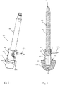
- Fig. 3 shows a brake release device 1 according to the invention, with its main components, the functional unit 100, an electric drive unit 200 and a tank assembly 300, which is penetrated by a control cylinder assembly 400.
- the cover 301 passes through the actuating piston 401 of the actuating cylinder arrangement 400. It also has a connecting eyelet 402 at its end.
- the adjusting piston 401 is in Fig. 1 in its rest position, ie in its retracted position (second working position) shown.
- a connection box 203 is attached.
- Fig. 1 shows in perspective view the actuating cylinder assembly 400. It comprises the actuating piston 401, which is slidably received in a cylinder tube 403. At the lower end of the cylinder tube 403, an external thread 404 is provided with which the cylinder tube can be screwed into a corresponding receptacle 101 of the functional unit 100 (cf. Fig. 2 ).
- Into the receptacle 101 opens an inlet and outlet 102, via which the interior 405 (pressure chamber) of the cylinder tube 403 is filled with hydraulic fluid. Serves a not shown electric pump unit.
- the pressure chamber 405 When filling the pressure chamber 405 with hydraulic fluid an internal pressure is built there, which brings the actuating piston 401 against a force acting on the upper end spring force F of the brake assembly not shown in its first working position. In this case, the adjusting piston 401 is fully extended and releases the brake assembly.
- the cylinder tube 403 has a plurality of bores 406 designed as bores, into which sensors 407 are inserted.
- the sensors 407 are designed as inductive sensors and have a directed into the interior of the cylinder tube 403 end face 408, which serves as a signal-triggering sensor element.
- the end face 408 detects the approach of an annular shoulder 409 of the actuating piston 401, which serves as a triggering element.
- the sensors 407a and 407b thus capture the in Fig. 2 shown first working position of the actuating piston 401, in which the shoulder 409 in the region of the end face 408 of the sensors 407a and 407b is arranged.
- the one sensor 407a outputs a corresponding switching signal to the pump unit and switches it off.
- the second sensor 407b outputs a signal as a position signal to any control device either of the brake release device 1 itself or to a control unit of a system, of which the brake release device 1 is an integral part. The signal indicates the state "Brake released”.
- the spring force F causes the actuating piston to move in the direction of the force in the direction of the functional unit 100.
- the shoulder 409 leaves the region of the end faces 408 of the sensor 407a, 407b.
- This changes its signal which optionally triggers a switching operation, which sets the hydraulic pump back into operation to rebuild the pressure so far that the actuating piston 401 moves back to its first working position.
- a signal which optionally indicates that the brake release device 1 is no longer in its "brake released" state.
- the distance of the end face 408 can be changed to the peripheral surface of the paragraph 409.
- the responsiveness of the sensor 407a, 407b with respect to a change in the axial position of the shoulder 409 along the axis 410 is adjustable. If the end face 408 is close to the shoulder 409, then the detection is very sensitive severely. The signal changes as soon as the peripheral surface reaches the area of the end face 408. If the end face 408 farther away, the detection is "blurred” and somewhat delayed, so only when the paragraph 409 is moved further into the region of the end face 408.
- the plurality of wreath-mounted receptacles 406 allow the sensors 407a, 407b to be screwed into receptacles 406 which provide the sensors 407 with a favorable circumferential orientation of the cylinder tube 403 in the functional unit 100.
- the cylinder tube 403 is fixed via a lock nut 411. Subsequently, the sensor or sensors 407a, 407b are inserted into the preferred receptacles 406 and fixed there.
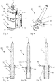
- Fig. 4 shows an embodiment of the actuating cylinder assembly 400 according to a second aspect of the invention.
- a further receiving arrangement is arranged on the cylinder tube 403, which is designed as a fixable outer ring 500.
- a receiving bore 501 is provided, in which a sensor 502 is mounted.
- This sensor 502 detects the position of an adjustable on the piston rod 412 triggering element, which is designed as a collar 503.
- Fig. 5a shows the actuating piston 401 in a so-called Resthub too, in which the adjusting piston 401 is brought when it is inserted under the action of the spring force F in the cylinder tube.
- the adjusting ring 503 is arranged so that it only comes into the effective range of the sensor 502 when the residual stroke H R falls below an adjustable limit.
- the residual stroke H R changes when the brake is used, with increasing wear of the brake elements (brake disc, brake pads). If, therefore, a certain residual stroke is undershot, the sensor 502 indicates this, namely when the adjusting ring 503 reaches the effective range of the sensor 502. This then sends a signal to a display and / or control device.
- the display device may be configured in the form of one or more LED elements 600, which emit a light signal in response to this switching signal.
- the light signal can be, for example, that a color change from green to red takes place or a blinking frequency is increased.
- This signal change then indicates a revision state, which is triggered by the reduction of the residual stroke H R or the undershooting of a minimum residual stroke.
- Fig. 5b shows the actuating cylinder assembly 401 in the extended state (see also Fig. 2 ). In this position, the adjusting ring 503 is not detected by the sensor 502.
- Fig. 5c shows the actuator piston 401 in the fully retracted position.
- the position of the adjusting ring 503 is detected by the sensor 502.
- the collar 503 does not serve to indicate a revision condition, but to represent a "brake-closed" condition.
- sensors 502 which are arranged in an axially offset position. One then signals the "brake closed” state and, if necessary, the revision state.
- the in the Fig. 5a to 5c arrangement shown can also with the in the Fig. 1 and 2 arrangements are shown combined. This can be used to combine the setting, control and display options.
Landscapes
- Engineering & Computer Science (AREA)
- General Engineering & Computer Science (AREA)
- Mechanical Engineering (AREA)
- Transportation (AREA)
- Physics & Mathematics (AREA)
- Electromagnetism (AREA)
- Braking Arrangements (AREA)
- Valves And Accessory Devices For Braking Systems (AREA)
Priority Applications (2)
| Application Number | Priority Date | Filing Date | Title |
|---|---|---|---|
| RS20200388A RS60100B1 (sr) | 2017-04-21 | 2018-04-17 | Uređaj otkočnika kočnice sa sklopom servocilindra |
| PL18167726T PL3392106T3 (pl) | 2017-04-21 | 2018-04-17 | Zwalniak hamulca z układem siłownika nastawczego |
Applications Claiming Priority (1)
| Application Number | Priority Date | Filing Date | Title |
|---|---|---|---|
| DE102017108489.4A DE102017108489A1 (de) | 2017-04-21 | 2017-04-21 | Bremslüftgerät mit stellzylinderanordnung |
Publications (3)
| Publication Number | Publication Date |
|---|---|
| EP3392106A2 true EP3392106A2 (fr) | 2018-10-24 |
| EP3392106A3 EP3392106A3 (fr) | 2018-12-12 |
| EP3392106B1 EP3392106B1 (fr) | 2020-03-04 |
Family
ID=62091661
Family Applications (1)
| Application Number | Title | Priority Date | Filing Date |
|---|---|---|---|
| EP18167726.1A Active EP3392106B1 (fr) | 2017-04-21 | 2018-04-17 | Dispositif de levage de frein avec un dispositif de cylindre d'actionnement |
Country Status (6)
| Country | Link |
|---|---|
| EP (1) | EP3392106B1 (fr) |
| DE (1) | DE102017108489A1 (fr) |
| DK (1) | DK3392106T3 (fr) |
| ES (1) | ES2785123T3 (fr) |
| PL (1) | PL3392106T3 (fr) |
| RS (1) | RS60100B1 (fr) |
Family Cites Families (15)
| Publication number | Priority date | Publication date | Assignee | Title |
|---|---|---|---|---|
| US2276591A (en) * | 1940-07-27 | 1942-03-17 | William R Ray | Operator |
| US3828556A (en) * | 1973-01-26 | 1974-08-13 | Johnson Service Co | Hydraulic actuator |
| DE3400600A1 (de) * | 1983-02-18 | 1984-08-23 | Lucas Industries P.L.C., Birmingham, West Midlands | Betaetigungsvorrichtung fuer eine bremse, insbesondere vollbelag-scheibenbremse |
| US4936143A (en) | 1989-04-28 | 1990-06-26 | Eaton Corporation | Cylinders having piston position measurement |
| DE29521637U1 (de) | 1995-01-26 | 1997-12-11 | Rotovolumetric AG, Ebikon | Einrichtung mit einem Zylinder, einem in diesem verschiebbaren Kolben und einem im Zylinder angeordneten, induktiven Meßwandler |
| DE19955270A1 (de) | 1999-11-17 | 2001-05-23 | Roemheld A Gmbh & Co Kg | System zur Überwachung von Hydraulikzylindern |
| EP1895170B1 (fr) | 2005-06-21 | 2016-03-09 | ASA Electronics Industry Co., Ltd. | Unité de commande de cylindres |
| JP4847060B2 (ja) * | 2005-07-15 | 2011-12-28 | 日立オートモティブシステムズ株式会社 | 交流モータ駆動装置及びその制御方法 |
| JP4529093B2 (ja) * | 2007-12-19 | 2010-08-25 | Smc株式会社 | 流体圧シリンダのピストン位置検出装置 |
| DE102011085273A1 (de) * | 2010-11-05 | 2012-05-10 | Continental Teves Ag & Co. Ohg | Bremsanlage für Kraftfahrzeuge |
| DE102012205859A1 (de) * | 2011-04-19 | 2012-10-25 | Continental Teves Ag & Co. Ohg | Bremsanlage für Kraftfahrzeuge sowie Verfahren zum Betrieb einer Bremsanlage |
| DE102012212836A1 (de) * | 2011-08-17 | 2013-02-21 | Continental Teves Ag & Co. Ohg | Bremsanlage für Kraftfahrzeuge |
| DE102011114072C5 (de) * | 2011-09-22 | 2021-04-22 | Knorr-Bremse Systeme für Nutzfahrzeuge GmbH | Fahrerassistenzsystem mit autonomer Bremsung bis zum Stillstand |
| DE102013105446A1 (de) | 2013-05-28 | 2014-12-04 | Pintsch Bubenzer Gmbh | Elektrohydraulisches Bremslüftgerät und Bremsanordnung |
| DE102013105445B4 (de) * | 2013-05-28 | 2015-08-20 | Pintsch Bubenzer Gmbh | Funktionseinheit und Elektrohydraulisches Bremslüftgerät mit einer Solchen |
-
2017
- 2017-04-21 DE DE102017108489.4A patent/DE102017108489A1/de not_active Ceased
-
2018
- 2018-04-17 RS RS20200388A patent/RS60100B1/sr unknown
- 2018-04-17 PL PL18167726T patent/PL3392106T3/pl unknown
- 2018-04-17 ES ES18167726T patent/ES2785123T3/es active Active
- 2018-04-17 DK DK18167726.1T patent/DK3392106T3/da active
- 2018-04-17 EP EP18167726.1A patent/EP3392106B1/fr active Active
Also Published As
| Publication number | Publication date |
|---|---|
| EP3392106B1 (fr) | 2020-03-04 |
| DE102017108489A1 (de) | 2018-10-25 |
| EP3392106A3 (fr) | 2018-12-12 |
| DK3392106T3 (da) | 2020-06-08 |
| RS60100B1 (sr) | 2020-05-29 |
| PL3392106T3 (pl) | 2020-08-24 |
| ES2785123T3 (es) | 2020-10-06 |
Similar Documents
| Publication | Publication Date | Title |
|---|---|---|
| DE69914968T2 (de) | Elektohydraulische Steuereinheit | |
| DE102012018134B4 (de) | Bremshauptzylinder | |
| DE102015104133A1 (de) | Spannvorrichtung zum Dehnen eines Gewindebolzens | |
| DE102010028762A1 (de) | Vorrichtung zum Bestimmen eines Betriebszustandes von wenigstens einer bidirektional betätigbaren hydraulischen Stelleinrichtung eines Schaltelementes einer Getriebeeinrichtung | |
| DE112019000578B4 (de) | Fluidleckage-erfassungsvorrichtung und hin- und herbewegende fluiddruckvorrichtung | |
| DE102016223802B4 (de) | Detektionseinrichtung und Schmierstoffverteiler | |
| DE102021204102A1 (de) | Schmiermittelpumpenordnung | |
| EP3438511A1 (fr) | Bague d'étanchéité glissante d'un retardateur hydrodynamique ainsi que retardateur hydrodynamique | |
| DE102016223798B4 (de) | Detektionseinrichtung und Schmierstoffverteiler | |
| DE2822903C3 (de) | Strömungswächter (Sichtindikator) für eine Einspritzschmiervorrichtung | |
| DE1948952A1 (de) | Absperrventil zur Steuerung der Zufuehrung von Druckmedium in eine Mediumaufnahmevorrichtung | |
| DE112014000157B4 (de) | Zylinder mit Stoßdämpfungsfunktion | |
| EP3256743A1 (fr) | Soupape pourvue d'un tiroir de distribution guidé mobile longitudinalement dans un corps de soupape | |
| EP2669543A2 (fr) | Dispositif de ventilation et d'actionnement automatique d'un système de frein | |
| EP2685142B1 (fr) | Vanne à boisseau conique | |
| EP3392106B1 (fr) | Dispositif de levage de frein avec un dispositif de cylindre d'actionnement | |
| EP2948963B1 (fr) | Appareil actionné par un électro-aimant et comprenant une liaison par vissage encapsulée | |
| DE102017107494B4 (de) | Verfahren zur Prüfung einer mechanischen Blockade eines automatisierten Kupplungsbetätigungssystems | |
| WO2014079430A1 (fr) | Unité piston-cylindre | |
| DE102017109828A1 (de) | Fluidsteuerung, Bremslüftgerät, Bremsanordnung | |
| DE102006001893B4 (de) | Parkbremse für ein Kraftfahrzeug | |
| EP4411162B1 (fr) | Frein avec un dispositif pour déterminer une limite d'usure | |
| EP3699438A1 (fr) | Système de clapet anti-retour à commande électronique | |
| EP4384739B1 (fr) | Vanne de levage pourvue d'un entraînement de levage | |
| EP3054170B1 (fr) | Unite de cylindre a pistons dotee d'une bague de reglage |
Legal Events
| Date | Code | Title | Description |
|---|---|---|---|
| PUAI | Public reference made under article 153(3) epc to a published international application that has entered the european phase |
Free format text: ORIGINAL CODE: 0009012 |
|
| STAA | Information on the status of an ep patent application or granted ep patent |
Free format text: STATUS: THE APPLICATION HAS BEEN PUBLISHED |
|
| AK | Designated contracting states |
Kind code of ref document: A2 Designated state(s): AL AT BE BG CH CY CZ DE DK EE ES FI FR GB GR HR HU IE IS IT LI LT LU LV MC MK MT NL NO PL PT RO RS SE SI SK SM TR |
|
| AX | Request for extension of the european patent |
Extension state: BA ME |
|
| PUAL | Search report despatched |
Free format text: ORIGINAL CODE: 0009013 |
|
| AK | Designated contracting states |
Kind code of ref document: A3 Designated state(s): AL AT BE BG CH CY CZ DE DK EE ES FI FR GB GR HR HU IE IS IT LI LT LU LV MC MK MT NL NO PL PT RO RS SE SI SK SM TR |
|
| AX | Request for extension of the european patent |
Extension state: BA ME |
|
| RIC1 | Information provided on ipc code assigned before grant |
Ipc: F16D 59/02 20060101ALI20181108BHEP Ipc: B60T 13/22 20060101AFI20181108BHEP Ipc: F16D 65/28 20060101ALI20181108BHEP Ipc: F16D 66/00 20060101ALI20181108BHEP |
|
| STAA | Information on the status of an ep patent application or granted ep patent |
Free format text: STATUS: REQUEST FOR EXAMINATION WAS MADE |
|
| 17P | Request for examination filed |
Effective date: 20190611 |
|
| RBV | Designated contracting states (corrected) |
Designated state(s): AL AT BE BG CH CY CZ DE DK EE ES FI FR GB GR HR HU IE IS IT LI LT LU LV MC MK MT NL NO PL PT RO RS SE SI SK SM TR |
|
| GRAP | Despatch of communication of intention to grant a patent |
Free format text: ORIGINAL CODE: EPIDOSNIGR1 |
|
| STAA | Information on the status of an ep patent application or granted ep patent |
Free format text: STATUS: GRANT OF PATENT IS INTENDED |
|
| RIC1 | Information provided on ipc code assigned before grant |
Ipc: F16D 66/00 20060101ALI20191002BHEP Ipc: F16D 65/28 20060101ALI20191002BHEP Ipc: F16D 121/06 20120101ALN20191002BHEP Ipc: F16D 59/02 20060101ALI20191002BHEP Ipc: B60T 13/22 20060101AFI20191002BHEP |
|
| INTG | Intention to grant announced |
Effective date: 20191023 |
|
| GRAS | Grant fee paid |
Free format text: ORIGINAL CODE: EPIDOSNIGR3 |
|
| GRAA | (expected) grant |
Free format text: ORIGINAL CODE: 0009210 |
|
| STAA | Information on the status of an ep patent application or granted ep patent |
Free format text: STATUS: THE PATENT HAS BEEN GRANTED |
|
| AK | Designated contracting states |
Kind code of ref document: B1 Designated state(s): AL AT BE BG CH CY CZ DE DK EE ES FI FR GB GR HR HU IE IS IT LI LT LU LV MC MK MT NL NO PL PT RO RS SE SI SK SM TR |
|
| REG | Reference to a national code |
Ref country code: GB Ref legal event code: FG4D Free format text: NOT ENGLISH |
|
| REG | Reference to a national code |
Ref country code: CH Ref legal event code: EP |
|
| REG | Reference to a national code |
Ref country code: AT Ref legal event code: REF Ref document number: 1240027 Country of ref document: AT Kind code of ref document: T Effective date: 20200315 |
|
| REG | Reference to a national code |
Ref country code: DE Ref legal event code: R096 Ref document number: 502018000869 Country of ref document: DE |
|
| REG | Reference to a national code |
Ref country code: IE Ref legal event code: FG4D Free format text: LANGUAGE OF EP DOCUMENT: GERMAN |
|
| REG | Reference to a national code |
Ref country code: NL Ref legal event code: FP |
|
| REG | Reference to a national code |
Ref country code: DK Ref legal event code: T3 Effective date: 20200602 |
|
| PG25 | Lapsed in a contracting state [announced via postgrant information from national office to epo] |
Ref country code: FI Free format text: LAPSE BECAUSE OF FAILURE TO SUBMIT A TRANSLATION OF THE DESCRIPTION OR TO PAY THE FEE WITHIN THE PRESCRIBED TIME-LIMIT Effective date: 20200304 Ref country code: NO Free format text: LAPSE BECAUSE OF FAILURE TO SUBMIT A TRANSLATION OF THE DESCRIPTION OR TO PAY THE FEE WITHIN THE PRESCRIBED TIME-LIMIT Effective date: 20200604 |
|
| REG | Reference to a national code |
Ref country code: SK Ref legal event code: T3 Ref document number: E 34142 Country of ref document: SK |
|
| PG25 | Lapsed in a contracting state [announced via postgrant information from national office to epo] |
Ref country code: BG Free format text: LAPSE BECAUSE OF FAILURE TO SUBMIT A TRANSLATION OF THE DESCRIPTION OR TO PAY THE FEE WITHIN THE PRESCRIBED TIME-LIMIT Effective date: 20200604 Ref country code: SE Free format text: LAPSE BECAUSE OF FAILURE TO SUBMIT A TRANSLATION OF THE DESCRIPTION OR TO PAY THE FEE WITHIN THE PRESCRIBED TIME-LIMIT Effective date: 20200304 Ref country code: HR Free format text: LAPSE BECAUSE OF FAILURE TO SUBMIT A TRANSLATION OF THE DESCRIPTION OR TO PAY THE FEE WITHIN THE PRESCRIBED TIME-LIMIT Effective date: 20200304 Ref country code: GR Free format text: LAPSE BECAUSE OF FAILURE TO SUBMIT A TRANSLATION OF THE DESCRIPTION OR TO PAY THE FEE WITHIN THE PRESCRIBED TIME-LIMIT Effective date: 20200605 Ref country code: LV Free format text: LAPSE BECAUSE OF FAILURE TO SUBMIT A TRANSLATION OF THE DESCRIPTION OR TO PAY THE FEE WITHIN THE PRESCRIBED TIME-LIMIT Effective date: 20200304 |
|
| REG | Reference to a national code |
Ref country code: LT Ref legal event code: MG4D |
|
| REG | Reference to a national code |
Ref country code: ES Ref legal event code: FG2A Ref document number: 2785123 Country of ref document: ES Kind code of ref document: T3 Effective date: 20201006 |
|
| PG25 | Lapsed in a contracting state [announced via postgrant information from national office to epo] |
Ref country code: PT Free format text: LAPSE BECAUSE OF FAILURE TO SUBMIT A TRANSLATION OF THE DESCRIPTION OR TO PAY THE FEE WITHIN THE PRESCRIBED TIME-LIMIT Effective date: 20200729 Ref country code: RO Free format text: LAPSE BECAUSE OF FAILURE TO SUBMIT A TRANSLATION OF THE DESCRIPTION OR TO PAY THE FEE WITHIN THE PRESCRIBED TIME-LIMIT Effective date: 20200304 Ref country code: IS Free format text: LAPSE BECAUSE OF FAILURE TO SUBMIT A TRANSLATION OF THE DESCRIPTION OR TO PAY THE FEE WITHIN THE PRESCRIBED TIME-LIMIT Effective date: 20200704 Ref country code: LT Free format text: LAPSE BECAUSE OF FAILURE TO SUBMIT A TRANSLATION OF THE DESCRIPTION OR TO PAY THE FEE WITHIN THE PRESCRIBED TIME-LIMIT Effective date: 20200304 Ref country code: EE Free format text: LAPSE BECAUSE OF FAILURE TO SUBMIT A TRANSLATION OF THE DESCRIPTION OR TO PAY THE FEE WITHIN THE PRESCRIBED TIME-LIMIT Effective date: 20200304 Ref country code: SM Free format text: LAPSE BECAUSE OF FAILURE TO SUBMIT A TRANSLATION OF THE DESCRIPTION OR TO PAY THE FEE WITHIN THE PRESCRIBED TIME-LIMIT Effective date: 20200304 |
|
| REG | Reference to a national code |
Ref country code: DE Ref legal event code: R026 Ref document number: 502018000869 Country of ref document: DE |
|
| PLBI | Opposition filed |
Free format text: ORIGINAL CODE: 0009260 |
|
| PLAX | Notice of opposition and request to file observation + time limit sent |
Free format text: ORIGINAL CODE: EPIDOSNOBS2 |
|
| PG25 | Lapsed in a contracting state [announced via postgrant information from national office to epo] |
Ref country code: MC Free format text: LAPSE BECAUSE OF FAILURE TO SUBMIT A TRANSLATION OF THE DESCRIPTION OR TO PAY THE FEE WITHIN THE PRESCRIBED TIME-LIMIT Effective date: 20200304 |
|
| 26 | Opposition filed |
Opponent name: EMG AUTOMATION GMBH Effective date: 20201204 |
|
| PG25 | Lapsed in a contracting state [announced via postgrant information from national office to epo] |
Ref country code: LU Free format text: LAPSE BECAUSE OF NON-PAYMENT OF DUE FEES Effective date: 20200417 |
|
| PG25 | Lapsed in a contracting state [announced via postgrant information from national office to epo] |
Ref country code: SI Free format text: LAPSE BECAUSE OF FAILURE TO SUBMIT A TRANSLATION OF THE DESCRIPTION OR TO PAY THE FEE WITHIN THE PRESCRIBED TIME-LIMIT Effective date: 20200304 |
|
| PG25 | Lapsed in a contracting state [announced via postgrant information from national office to epo] |
Ref country code: IE Free format text: LAPSE BECAUSE OF NON-PAYMENT OF DUE FEES Effective date: 20200417 |
|
| REG | Reference to a national code |
Ref country code: DE Ref legal event code: R081 Ref document number: 502018000869 Country of ref document: DE Owner name: DELLNER BUBENZER GERMANY GMBH, DE Free format text: FORMER OWNER: PINTSCH BUBENZER GMBH, 57548 KIRCHEN, DE |
|
| RAP4 | Party data changed (patent owner data changed or rights of a patent transferred) |
Owner name: DELLNER BUBENZER GERMANY GMBH |
|
| PLBB | Reply of patent proprietor to notice(s) of opposition received |
Free format text: ORIGINAL CODE: EPIDOSNOBS3 |
|
| PG25 | Lapsed in a contracting state [announced via postgrant information from national office to epo] |
Ref country code: CH Free format text: LAPSE BECAUSE OF NON-PAYMENT OF DUE FEES Effective date: 20210430 Ref country code: LI Free format text: LAPSE BECAUSE OF NON-PAYMENT OF DUE FEES Effective date: 20210430 |
|
| PG25 | Lapsed in a contracting state [announced via postgrant information from national office to epo] |
Ref country code: TR Free format text: LAPSE BECAUSE OF FAILURE TO SUBMIT A TRANSLATION OF THE DESCRIPTION OR TO PAY THE FEE WITHIN THE PRESCRIBED TIME-LIMIT Effective date: 20200304 Ref country code: MT Free format text: LAPSE BECAUSE OF FAILURE TO SUBMIT A TRANSLATION OF THE DESCRIPTION OR TO PAY THE FEE WITHIN THE PRESCRIBED TIME-LIMIT Effective date: 20200304 Ref country code: CY Free format text: LAPSE BECAUSE OF FAILURE TO SUBMIT A TRANSLATION OF THE DESCRIPTION OR TO PAY THE FEE WITHIN THE PRESCRIBED TIME-LIMIT Effective date: 20200304 |
|
| PG25 | Lapsed in a contracting state [announced via postgrant information from national office to epo] |
Ref country code: MK Free format text: LAPSE BECAUSE OF FAILURE TO SUBMIT A TRANSLATION OF THE DESCRIPTION OR TO PAY THE FEE WITHIN THE PRESCRIBED TIME-LIMIT Effective date: 20200304 Ref country code: AL Free format text: LAPSE BECAUSE OF FAILURE TO SUBMIT A TRANSLATION OF THE DESCRIPTION OR TO PAY THE FEE WITHIN THE PRESCRIBED TIME-LIMIT Effective date: 20200304 |
|
| REG | Reference to a national code |
Ref country code: DE Ref legal event code: R100 Ref document number: 502018000869 Country of ref document: DE |
|
| GBPC | Gb: european patent ceased through non-payment of renewal fee |
Effective date: 20220417 |
|
| PG25 | Lapsed in a contracting state [announced via postgrant information from national office to epo] |
Ref country code: GB Free format text: LAPSE BECAUSE OF NON-PAYMENT OF DUE FEES Effective date: 20220417 |
|
| REG | Reference to a national code |
Ref country code: BE Ref legal event code: HC Owner name: DELLNER BUBENZER GERMANY GMBH; DE Free format text: DETAILS ASSIGNMENT: CHANGE OF OWNER(S), CHANGE OF OWNER(S) NAME; FORMER OWNER NAME: PINTSCH BUBENZER GMBH Effective date: 20230116 |
|
| REG | Reference to a national code |
Ref country code: NL Ref legal event code: HC Owner name: DELLNER BUBENZER GERMANY GMBH; DE Free format text: DETAILS ASSIGNMENT: CHANGE OF OWNER(S), CHANGE OF OWNER(S) NAME; FORMER OWNER NAME: PINTSCH BUBENZER GMBH Effective date: 20230418 |
|
| REG | Reference to a national code |
Ref country code: SK Ref legal event code: TC4A Ref document number: E 34142 Country of ref document: SK Owner name: DELLNER BUBENZER GERMANY GMBH, KIRCHENWEHBACH, DE Effective date: 20230519 |
|
| PLCK | Communication despatched that opposition was rejected |
Free format text: ORIGINAL CODE: EPIDOSNREJ1 |
|
| P01 | Opt-out of the competence of the unified patent court (upc) registered |
Effective date: 20230528 |
|
| PLBN | Opposition rejected |
Free format text: ORIGINAL CODE: 0009273 |
|
| STAA | Information on the status of an ep patent application or granted ep patent |
Free format text: STATUS: OPPOSITION REJECTED |
|
| 27O | Opposition rejected |
Effective date: 20221122 |
|
| REG | Reference to a national code |
Ref country code: AT Ref legal event code: HC Ref document number: 1240027 Country of ref document: AT Kind code of ref document: T Owner name: DELLNER BUBENZER GERMANY GMBH, DE Effective date: 20231023 |
|
| PGFP | Annual fee paid to national office [announced via postgrant information from national office to epo] |
Ref country code: NL Payment date: 20250422 Year of fee payment: 8 |
|
| PGFP | Annual fee paid to national office [announced via postgrant information from national office to epo] |
Ref country code: PL Payment date: 20250407 Year of fee payment: 8 Ref country code: DE Payment date: 20250417 Year of fee payment: 8 |
|
| PGFP | Annual fee paid to national office [announced via postgrant information from national office to epo] |
Ref country code: ES Payment date: 20250519 Year of fee payment: 8 Ref country code: DK Payment date: 20250423 Year of fee payment: 8 |
|
| PGFP | Annual fee paid to national office [announced via postgrant information from national office to epo] |
Ref country code: RS Payment date: 20250407 Year of fee payment: 8 |
|
| PGFP | Annual fee paid to national office [announced via postgrant information from national office to epo] |
Ref country code: BE Payment date: 20250422 Year of fee payment: 8 Ref country code: IT Payment date: 20250430 Year of fee payment: 8 |
|
| PGFP | Annual fee paid to national office [announced via postgrant information from national office to epo] |
Ref country code: FR Payment date: 20250428 Year of fee payment: 8 |
|
| PGFP | Annual fee paid to national office [announced via postgrant information from national office to epo] |
Ref country code: AT Payment date: 20250416 Year of fee payment: 8 |
|
| PGFP | Annual fee paid to national office [announced via postgrant information from national office to epo] |
Ref country code: SK Payment date: 20250411 Year of fee payment: 8 |
|
| PGFP | Annual fee paid to national office [announced via postgrant information from national office to epo] |
Ref country code: CZ Payment date: 20250404 Year of fee payment: 8 |
|
| PG25 | Lapsed in a contracting state [announced via postgrant information from national office to epo] |
Ref country code: IS Free format text: LAPSE BECAUSE OF NON-PAYMENT OF DUE FEES Effective date: 20200704 |