EP3392111B1 - Procédé et dispositif de détermination d'une distraction visuelle d'un conducteur d'un véhicule - Google Patents
Procédé et dispositif de détermination d'une distraction visuelle d'un conducteur d'un véhicule Download PDFInfo
- Publication number
- EP3392111B1 EP3392111B1 EP18152094.1A EP18152094A EP3392111B1 EP 3392111 B1 EP3392111 B1 EP 3392111B1 EP 18152094 A EP18152094 A EP 18152094A EP 3392111 B1 EP3392111 B1 EP 3392111B1
- Authority
- EP
- European Patent Office
- Prior art keywords
- attention
- driver
- map
- vehicle
- information
- Prior art date
- Legal status (The legal status is an assumption and is not a legal conclusion. Google has not performed a legal analysis and makes no representation as to the accuracy of the status listed.)
- Active
Links
Images

Classifications
-
- B—PERFORMING OPERATIONS; TRANSPORTING
- B60—VEHICLES IN GENERAL
- B60W—CONJOINT CONTROL OF VEHICLE SUB-UNITS OF DIFFERENT TYPE OR DIFFERENT FUNCTION; CONTROL SYSTEMS SPECIALLY ADAPTED FOR HYBRID VEHICLES; ROAD VEHICLE DRIVE CONTROL SYSTEMS FOR PURPOSES NOT RELATED TO THE CONTROL OF A PARTICULAR SUB-UNIT
- B60W40/00—Estimation or calculation of non-directly measurable driving parameters for road vehicle drive control systems not related to the control of a particular sub unit, e.g. by using mathematical models
- B60W40/08—Estimation or calculation of non-directly measurable driving parameters for road vehicle drive control systems not related to the control of a particular sub unit, e.g. by using mathematical models related to drivers or passengers
-
- B—PERFORMING OPERATIONS; TRANSPORTING
- B60—VEHICLES IN GENERAL
- B60K—ARRANGEMENT OR MOUNTING OF PROPULSION UNITS OR OF TRANSMISSIONS IN VEHICLES; ARRANGEMENT OR MOUNTING OF PLURAL DIVERSE PRIME-MOVERS IN VEHICLES; AUXILIARY DRIVES FOR VEHICLES; INSTRUMENTATION OR DASHBOARDS FOR VEHICLES; ARRANGEMENTS IN CONNECTION WITH COOLING, AIR INTAKE, GAS EXHAUST OR FUEL SUPPLY OF PROPULSION UNITS IN VEHICLES
- B60K35/00—Instruments specially adapted for vehicles; Arrangement of instruments in or on vehicles
- B60K35/10—Input arrangements, i.e. from user to vehicle, associated with vehicle functions or specially adapted therefor
-
- G—PHYSICS
- G06—COMPUTING OR CALCULATING; COUNTING
- G06V—IMAGE OR VIDEO RECOGNITION OR UNDERSTANDING
- G06V20/00—Scenes; Scene-specific elements
- G06V20/50—Context or environment of the image
- G06V20/59—Context or environment of the image inside of a vehicle, e.g. relating to seat occupancy, driver state or inner lighting conditions
- G06V20/597—Recognising the driver's state or behaviour, e.g. attention or drowsiness
-
- G—PHYSICS
- G06—COMPUTING OR CALCULATING; COUNTING
- G06V—IMAGE OR VIDEO RECOGNITION OR UNDERSTANDING
- G06V40/00—Recognition of biometric, human-related or animal-related patterns in image or video data
- G06V40/10—Human or animal bodies, e.g. vehicle occupants or pedestrians; Body parts, e.g. hands
- G06V40/18—Eye characteristics, e.g. of the iris
- G06V40/19—Sensors therefor
-
- B—PERFORMING OPERATIONS; TRANSPORTING
- B60—VEHICLES IN GENERAL
- B60K—ARRANGEMENT OR MOUNTING OF PROPULSION UNITS OR OF TRANSMISSIONS IN VEHICLES; ARRANGEMENT OR MOUNTING OF PLURAL DIVERSE PRIME-MOVERS IN VEHICLES; AUXILIARY DRIVES FOR VEHICLES; INSTRUMENTATION OR DASHBOARDS FOR VEHICLES; ARRANGEMENTS IN CONNECTION WITH COOLING, AIR INTAKE, GAS EXHAUST OR FUEL SUPPLY OF PROPULSION UNITS IN VEHICLES
- B60K2360/00—Indexing scheme associated with groups B60K35/00 or B60K37/00 relating to details of instruments or dashboards
- B60K2360/149—Instrument input by detecting viewing direction not otherwise provided for
-
- B—PERFORMING OPERATIONS; TRANSPORTING
- B60—VEHICLES IN GENERAL
- B60W—CONJOINT CONTROL OF VEHICLE SUB-UNITS OF DIFFERENT TYPE OR DIFFERENT FUNCTION; CONTROL SYSTEMS SPECIALLY ADAPTED FOR HYBRID VEHICLES; ROAD VEHICLE DRIVE CONTROL SYSTEMS FOR PURPOSES NOT RELATED TO THE CONTROL OF A PARTICULAR SUB-UNIT
- B60W40/00—Estimation or calculation of non-directly measurable driving parameters for road vehicle drive control systems not related to the control of a particular sub unit, e.g. by using mathematical models
- B60W40/08—Estimation or calculation of non-directly measurable driving parameters for road vehicle drive control systems not related to the control of a particular sub unit, e.g. by using mathematical models related to drivers or passengers
- B60W2040/0818—Inactivity or incapacity of driver
-
- B—PERFORMING OPERATIONS; TRANSPORTING
- B60—VEHICLES IN GENERAL
- B60W—CONJOINT CONTROL OF VEHICLE SUB-UNITS OF DIFFERENT TYPE OR DIFFERENT FUNCTION; CONTROL SYSTEMS SPECIALLY ADAPTED FOR HYBRID VEHICLES; ROAD VEHICLE DRIVE CONTROL SYSTEMS FOR PURPOSES NOT RELATED TO THE CONTROL OF A PARTICULAR SUB-UNIT
- B60W2552/00—Input parameters relating to infrastructure
- B60W2552/05—Type of road, e.g. motorways, local streets, paved or unpaved roads
-
- B—PERFORMING OPERATIONS; TRANSPORTING
- B60—VEHICLES IN GENERAL
- B60W—CONJOINT CONTROL OF VEHICLE SUB-UNITS OF DIFFERENT TYPE OR DIFFERENT FUNCTION; CONTROL SYSTEMS SPECIALLY ADAPTED FOR HYBRID VEHICLES; ROAD VEHICLE DRIVE CONTROL SYSTEMS FOR PURPOSES NOT RELATED TO THE CONTROL OF A PARTICULAR SUB-UNIT
- B60W2552/00—Input parameters relating to infrastructure
- B60W2552/10—Number of lanes
-
- B—PERFORMING OPERATIONS; TRANSPORTING
- B60—VEHICLES IN GENERAL
- B60W—CONJOINT CONTROL OF VEHICLE SUB-UNITS OF DIFFERENT TYPE OR DIFFERENT FUNCTION; CONTROL SYSTEMS SPECIALLY ADAPTED FOR HYBRID VEHICLES; ROAD VEHICLE DRIVE CONTROL SYSTEMS FOR PURPOSES NOT RELATED TO THE CONTROL OF A PARTICULAR SUB-UNIT
- B60W2552/00—Input parameters relating to infrastructure
- B60W2552/30—Road curve radius
-
- B—PERFORMING OPERATIONS; TRANSPORTING
- B60—VEHICLES IN GENERAL
- B60W—CONJOINT CONTROL OF VEHICLE SUB-UNITS OF DIFFERENT TYPE OR DIFFERENT FUNCTION; CONTROL SYSTEMS SPECIALLY ADAPTED FOR HYBRID VEHICLES; ROAD VEHICLE DRIVE CONTROL SYSTEMS FOR PURPOSES NOT RELATED TO THE CONTROL OF A PARTICULAR SUB-UNIT
- B60W2552/00—Input parameters relating to infrastructure
- B60W2552/53—Road markings, e.g. lane marker or crosswalk
-
- B—PERFORMING OPERATIONS; TRANSPORTING
- B60—VEHICLES IN GENERAL
- B60W—CONJOINT CONTROL OF VEHICLE SUB-UNITS OF DIFFERENT TYPE OR DIFFERENT FUNCTION; CONTROL SYSTEMS SPECIALLY ADAPTED FOR HYBRID VEHICLES; ROAD VEHICLE DRIVE CONTROL SYSTEMS FOR PURPOSES NOT RELATED TO THE CONTROL OF A PARTICULAR SUB-UNIT
- B60W2554/00—Input parameters relating to objects
- B60W2554/40—Dynamic objects, e.g. animals, windblown objects
- B60W2554/404—Characteristics
- B60W2554/4041—Position
-
- B—PERFORMING OPERATIONS; TRANSPORTING
- B60—VEHICLES IN GENERAL
- B60W—CONJOINT CONTROL OF VEHICLE SUB-UNITS OF DIFFERENT TYPE OR DIFFERENT FUNCTION; CONTROL SYSTEMS SPECIALLY ADAPTED FOR HYBRID VEHICLES; ROAD VEHICLE DRIVE CONTROL SYSTEMS FOR PURPOSES NOT RELATED TO THE CONTROL OF A PARTICULAR SUB-UNIT
- B60W2556/00—Input parameters relating to data
- B60W2556/45—External transmission of data to or from the vehicle
- B60W2556/50—External transmission of data to or from the vehicle of positioning data, e.g. GPS [Global Positioning System] data
Definitions
- the invention is based on a device or a method according to the class of the independent claims.
- the present invention also relates to a computer program.
- the document GB 2 500 690 A reveals a driver assistance system.
- the document EP 2 743 117 A1 discloses a system and method for monitoring and reducing a driver impairment.
- a method for determining a visual distraction of a driver of a vehicle comprising the following steps: modeling an attention of the driver by forming an attention map using driver information that represents the direction of gaze and/or head posture of the driver and/or an orientation of an upper body of the driver detected by means of a sensor of the vehicle, wherein the attention map represents an actual distribution of the driver's attention in a two-dimensional coordinate system dependent on the direction of gaze and/or head posture, wherein the two-dimensional coordinate system maps at least a partial area of an environment of the vehicle;
- the vehicle’s sensor can, for example, be an interior sensor of the vehicle, such as an (infrared) camera or similar.
- the driver's knowledge of objects in the environment can be represented in the model. This is particularly relevant when there are changes in state, for example when a vehicle in front brakes.
- a further advantage is the possibility of modeling in detail the temporal dynamics of forgetting visual impressions, for example when the driver changes the direction of view.
- the spherical coordinate system has a polar angle range between minus 180 degrees and plus 180 degrees or, additionally or alternatively, an azimuth angle range between minus 60 degrees and plus 60 degrees. This enables an efficient simulation of the vehicle's surroundings using the coordinate system.
- the attention map or, additionally or alternatively, the attention requirement map is formed with a coordinate origin that represents a center point of a location area of the driver's head in the vehicle. This allows the influence of longitudinal deviations in the driver's head position to be minimized when determining the visual distraction.
- the driver information can be used to detect a staring gaze of the driver.
- the attention map can be formed depending on the detection of the staring gaze of the driver.
- a staring gaze can be understood as a gaze with little information content or a lack of information absorption. This embodiment can further increase the reliability of the method.
- the approach presented here also creates a device that is designed to carry out, control or implement the steps of a variant of a method presented here in corresponding devices.
- This embodiment of the invention in the form of a device can also solve the problem underlying the invention quickly and efficiently.
- the device can have at least one computing unit for processing signals or data, at least one storage unit for storing signals or data, at least one interface to a sensor or an actuator for reading in sensor signals from the sensor or for outputting of data or control signals to the actuator and/or at least one communication interface for reading in or outputting data that is embedded in a communication protocol.
- the computing unit can be, for example, a signal processor, a microcontroller or the like, wherein the storage unit can be a flash memory, an EPROM or a magnetic storage unit.
- the communication interface can be designed to read in or output data wirelessly and/or via a wired connection, wherein a communication interface that can read in or output wired data can read this data, for example, electrically or optically from a corresponding data transmission line or output it to a corresponding data transmission line.
- a device can be understood as an electrical device that processes sensor signals and outputs control and/or data signals depending on them.
- the device can have an interface that can be designed as hardware and/or software.
- the interfaces can, for example, be part of a so-called system ASIC, which contains a wide variety of functions of the device.
- the interfaces it is also possible for the interfaces to be separate integrated circuits or to consist at least partially of discrete components.
- the interfaces can be software modules that are present, for example, on a microcontroller alongside other software modules.
- the device controls the vehicle.
- the device can access sensor signals such as acceleration, pressure, steering angle or environment sensor signals, for example.
- the control is carried out via actuators such as brake or steering actuators or an engine control unit of the vehicle.
- a computer program product or computer program with program code which can be stored on a machine-readable carrier or storage medium such as a semiconductor memory, a hard disk memory or an optical memory and which is used to carry out, implement and/or control the steps of the method according to one of the above described embodiments, particularly when the program product or program is executed on a computer or device.
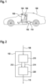
- Fig.1 shows a schematic representation of a vehicle 100 with a device 102 according to an embodiment.
- the device 102 is coupled to an interior sensor 104 for detecting a line of sight or a head posture of a driver 106, for example an (infrared) camera.
- the interior sensor 104 sends driver information 108 representing the line of sight or head posture to the device 102, which is designed to use it to model an attention map that represents an actual distribution of the driver's 106 attention.
- the attention map for example, maps lines of sight that accumulate to different degrees in different areas of an environment of the vehicle 100 depending on the distribution of attention, two-dimensionally in the manner of a heat map.
- the attention map is based on a two-dimensional coordinate system that, for example, represents an attention-relevant area of the vehicle environment.
- the attention map is based on a two-dimensional spherical coordinate system for simulating the vehicle environment.
- the device 102 is further designed to model areas of the vehicle environment that require increased attention from the driver in a corresponding attention requirement map analogous to the attention map using the two-dimensional coordinate system.
- the attention requirement map is also modeled using the driver information 108, i.e. depending on a respective viewing direction or head position of the driver 106 with respect to the vehicle environment.
- the attention requirement map thus represents a target distribution of the driver's attention 106.
- the device 102 determines the visual distraction of the driver 106. To determine the visual distraction of the driver 106, the device 102 performs a comparison between the two maps, for example by means of Difference formation. As a result of this comparison, the device 102 outputs a distraction value 110 representing the visual distraction. This is used, for example, by a control unit of the vehicle 100 to generate a warning to warn the driver 106 depending on the visual distraction or, for example in the context of a partially or highly automated control of the vehicle 100, a control signal to control at least one actuator of the vehicle 100, such as a steering or braking actuator.
- a control unit of the vehicle 100 to generate a warning to warn the driver 106 depending on the visual distraction or, for example in the context of a partially or highly automated control of the vehicle 100, a control signal to control at least one actuator of the vehicle 100, such as a steering or braking actuator.
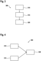
- Fig.2 shows a schematic representation of a device 102 according to an embodiment, for example a device previously described with reference to Fig.1 described device.
- the device 102 comprises a modeling unit 210, which is designed to read in the driver information 108 and use it to form the attention map. Furthermore, the modeling unit 210 is designed to model the attention requirement by forming the attention requirement map.
- the modeling unit 210 sends a first data set 212 representing the attention map and a second data set 214 representing the attention requirement map to a comparison unit 220, which is designed to compare the two maps with one another using the two data sets 212, 214 and thus determine the distraction value 110 representing the visual distraction of the driver.
- Fig. 3 shows a flow chart of a method 300 according to an embodiment.
- the method 300 for determining a visual distraction of a driver can be carried out, for example, using a device as described above with reference to the Figures 1 and 2 described.
- the driver's attention is modeled by creating the attention map.
- the attention requirement is modeled by creating the attention requirement map, for example in the form of a cold map.
- the two maps are compared with each other in a step 320 in order to determine the distraction value representing the driver's visual distraction.
- Fig.4 shows a flow chart of a method 300 according to an embodiment.
- a basic model for detecting impermissible visual distraction is shown.
- step 310 the detection of selective visual attention of the driver takes place by modeling the attention map and in step 315 the detection of the attention requirement from the environmental state by modeling the attention requirement map.
- step 320 a distraction hypothesis is created by detecting impermissible distraction based on a target-actual comparison between the two maps.
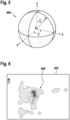
- Fig.5 shows a schematic representation of a coordinate system 500 for use in a method according to an embodiment, such as one described above with reference to the Figures 1 to 4 described method.
- a spherical coordinate system with the polar coordinates polar angle ⁇ and azimuth angle ⁇ is shown to represent directions of attention.
- So-called heat maps are used to model the driver's attention level and the attention requirement from the environment.
- spherical coordinates are used to transform directions of attention into a two-dimensional image (polar angle ⁇ and azimuth angle ⁇ ). Accordingly, such a heat map can be completely described using an n ⁇ m matrix.
- the attention requirement is described using a cold map that depicts "negative heat”.
- the origin 0 of this heat map should be in the center of a head box, i.e. in an area where the driver's head is usually located. Errors that arise because the driver's head is not in this position can be ignored, since the deviations in the head positions are small compared to the longitudinal distance to the objects being viewed outside the vehicle. Accordingly, the heat and cold maps are only used for objects outside the vehicle.
- these heat and cold maps are spanned on a sphere around the vehicle in order to be able to model the entire environment of the vehicle, for example with a value range for the polar angle ⁇ between minus 180 degrees and plus 180 degrees.
- the value range for the azimuth angle ⁇ can be smaller and is, for example, between minus 60 degrees and plus 60 degrees, where 0 degrees corresponds to a horizontal line.
- Fig.6 shows a schematic representation of an attention map 600 according to an embodiment.
- An example of a heat map is shown as an attention map for visualizing the distribution of attention.
- the vehicle environment is only indicated by way of example by a rectangle 602.
- map areas with different levels of accumulation of viewing directions are shown in different colors.
- Fig.7 shows a diagram illustrating an attention density function 700 for use in a method according to an embodiment, such as a method previously described with reference to the Figures 1 to 6 described method.
- the attention density is shown as a function of an eccentricity angle ⁇ .
- a more detailed description of the attention density function 700 can be found in the following description.
- the detection of the driver's selective visual attention is carried out by describing an accumulation of the viewing directions in a moving window.
- the window size is set to 5 seconds, for example, and describes the past 5 seconds.
- Various modular extensions are conceivable, each of which can increase the accuracy of the modeling. These are described as examples below.
- the eccentricity angle ⁇ is used concentrically to the driver's foveal axis.
- the attention density ie the "heat" density
- the attention map is then constructed.
- the temporal component of human recall is considered.
- glances expire after a certain period of time, for example after 5 seconds according to the window size mentioned above.
- a decay function is introduced with which past glances are multiplied according to their age.
- the staring eye In order to take staring eyes, i.e. looks with a lack of information intake, into account in the modeling, the staring eye is first detected accordingly, for example based on a saccade and fixation frequency. As soon as a staring eye of the driver is detected, the accumulation of gaze directions to the attention map, i.e. the heat map, is stopped so that no additional "heat” is taken into account for these periods. If this state is maintained for a longer period of time, this results in an empty heat map - the driver shows no attention whatsoever.
- the attention map i.e. the heat map
- mirror glances into one of the existing exterior mirrors always apply to the vehicle's surroundings, but usually to a rear area of the vehicle. Accordingly, according to one embodiment, mirror glances are counted as glances to the rear and are taken into account as such when calculating the attention map. For this reason, it is advantageous if the attention map is constructed around the entire vehicle and not just its front part.
- the overall attention requirement is shifted to the left or right, for example, and adjusted accordingly.
Landscapes
- Engineering & Computer Science (AREA)
- Physics & Mathematics (AREA)
- Transportation (AREA)
- Mechanical Engineering (AREA)
- Theoretical Computer Science (AREA)
- Mathematical Physics (AREA)
- General Physics & Mathematics (AREA)
- Multimedia (AREA)
- Automation & Control Theory (AREA)
- Health & Medical Sciences (AREA)
- General Health & Medical Sciences (AREA)
- Ophthalmology & Optometry (AREA)
- Human Computer Interaction (AREA)
- Chemical & Material Sciences (AREA)
- Combustion & Propulsion (AREA)
- Traffic Control Systems (AREA)
- Fittings On The Vehicle Exterior For Carrying Loads, And Devices For Holding Or Mounting Articles (AREA)
Claims (14)
- Procédé (300) de détermination d'une distraction visuelle d'un conducteur (106) d'un véhicule (100), le procédé (300) comprenant les étapes suivantes :la modélisation (310) d'une attention du conducteur (106) par création d'une carte d'attention (212 ; 600) en utilisant une information de conducteur (108) qui représente une direction de regard et/ou une position de la tête du conducteur (106) acquise au moyen d'un capteur (104) du véhicule (100) et/ou une orientation d'un torse du conducteur (106), la carte d'attention (212 ; 600) représentant une distribution réelle de l'attention du conducteur (106) dépendant de la direction de regard et/ou de la position de la tête dans un système de coordonnées bidimensionnel (500), le système de coordonnées bidimensionnel (500) reproduisant au moins une zone partielle d'un environnement du véhicule (100) ;la modélisation (315) d'un besoin d'attention par création d'une carte de besoin d'attention (214), la carte de besoin d'attention (214) représentant une distribution cible de l'attention du conducteur (106) dans le système de coordonnées bidimensionnel (500) ; etla comparaison (320) de la carte d'attention (212 ; 600) à la carte de besoin d'attention (214) afin de déterminer une valeur de distraction (110) représentant la distraction visuelle du conducteur (106).
- Procédé (300) selon la revendication 1, dans lequel, lors de l'étape de modélisation (310, 315), la carte d'attention (212 ; 600) et/ou la carte de besoin d'attention (214) est créée sur la base d'un système de coordonnées sphériques (500).
- Procédé (300) selon la revendication 2, dans lequel, lors de l'étape de modélisation (310, 315), le système de coordonnées sphériques (500) présente une plage d'angles polaires comprise entre moins 180 degrés et plus 180 degrés et/ou une plage d'angles azimutaux comprise entre moins 60 degrés et plus 60 degrés.
- Procédé (300) selon l'une des revendications précédentes, dans lequel, lors de l'étape de modélisation (310, 315), la carte d'attention (212 ; 600) et/ou la carte de besoin d'attention (214) est créée avec une origine de coordonnées (0) qui représente un centre d'une zone de maintien de la tête du conducteur (106) dans le véhicule (100).
- Procédé (300) selon l'une des revendications précédentes, dans lequel, lors de l'étape de comparaison (320), une différence entre la carte d'attention (212 ; 600) et la carte de besoin d'attention (214) est créée pour déterminer, en tant que valeur de distraction (110), une valeur représentant un écart positif et/ou négatif de la distribution réelle par rapport à la distribution cible.
- Procédé (300) selon l'une des revendications précédentes, dans lequel, lors de l'étape de modélisation (310), un angle d'excentricité concentrique à un axe de vision fovéal du conducteur (106) est déterminé en utilisant l'information de conducteur (108) et est utilisé pour modéliser une perception périphérique du conducteur (106), la carte d'attention (212 ; 600) étant créée en tenant compte de la perception périphérique modélisée.
- Procédé (300) selon l'une des revendications précédentes, dans lequel, lors de l'étape de modélisation (310), l'information de conducteur (108) est pondérée en fonction du temps en utilisant une fonction de pondération (800), la carte d'attention (212 ; 600) étant créée en utilisant l'information de conducteur pondérée (108) .
- Procédé (300) selon l'une des revendications précédentes, dans lequel, lors de l'étape de modélisation (310), l'information de conducteur (108) est utilisée pour détecter un regard fixe du conducteur (106), la carte d'attention (212 ; 600) étant créée en fonction de la détection du regard fixe du conducteur (106).
- Procédé (300) selon l'une des revendications précédentes, dans lequel, lors de l'étape de modélisation (310), un regard de rétroviseur et/ou d'épaule du conducteur (106) est déterminé en utilisant l'information de conducteur (108), la carte d'attention (212 ; 600) étant créée en tenant compte du regard de rétroviseur et/ou d'épaule.
- Procédé (300) selon l'une des revendications précédentes, dans lequel, lors de l'étape de modélisation (315), la carte de besoin d'attention (214) est créée en utilisant une information d'environnement fournie par un capteur d'environnement du véhicule (100) et/ou une information de guidage permettant de guider le véhicule (100) à l'aide d'une carte numérique.
- Procédé (300) selon la revendication 10, dans lequel, lors de l'étape de modélisation (315), l'information d'environnement et/ou l'information de guidage représente un type de route et/ou un nombre de voies de circulation et/ou une position de voie de circulation et/ou une courbure de voie de circulation et/ou une information d'objet qui représente une position et/ou un type et/ou un changement d'état d'au moins un objet dans l'environnement du véhicule (100).
- Dispositif (102) comprenant des unités (210, 220) qui sont configurées pour mettre en œuvre et/ou commander le procédé (300) selon l'une des revendications 1 à 11.
- Programme informatique, qui est configuré pour mettre en œuvre et/ou commander le procédé (300) selon l'une des revendications 1 à 11.
- Support de stockage lisible par machine, sur lequel est enregistré le programme informatique selon la revendication 13.
Applications Claiming Priority (1)
| Application Number | Priority Date | Filing Date | Title |
|---|---|---|---|
| DE102017202194.2A DE102017202194A1 (de) | 2017-02-13 | 2017-02-13 | Verfahren und Vorrichtung zum Ermitteln einer visuellen Ablenkung eines Fahrers eines Fahrzeugs |
Publications (2)
| Publication Number | Publication Date |
|---|---|
| EP3392111A1 EP3392111A1 (fr) | 2018-10-24 |
| EP3392111B1 true EP3392111B1 (fr) | 2024-07-10 |
Family
ID=61024569
Family Applications (1)
| Application Number | Title | Priority Date | Filing Date |
|---|---|---|---|
| EP18152094.1A Active EP3392111B1 (fr) | 2017-02-13 | 2018-01-17 | Procédé et dispositif de détermination d'une distraction visuelle d'un conducteur d'un véhicule |
Country Status (2)
| Country | Link |
|---|---|
| EP (1) | EP3392111B1 (fr) |
| DE (1) | DE102017202194A1 (fr) |
Families Citing this family (11)
| Publication number | Priority date | Publication date | Assignee | Title |
|---|---|---|---|---|
| DE102019217609A1 (de) * | 2019-11-14 | 2021-05-20 | Volkswagen Aktiengesellschaft | Verfahren zur Überwachung und Unterstützung eines Fahrers in einem Fahrzeug, Überwachungssystem, Fahrzeug |
| CN111400423B (zh) * | 2020-03-16 | 2023-05-16 | 北京千种幻影科技有限公司 | 基于多视图几何的智慧城市cim三维车辆位姿建模系统 |
| DE102020110417A1 (de) * | 2020-04-16 | 2021-10-21 | Valeo Schalter Und Sensoren Gmbh | Verfahren und System zur Assistenz eines Fahrers |
| DE102020003018B4 (de) | 2020-05-19 | 2025-12-31 | Mercedes-Benz Group AG | Verfahren zur Ermittlung einer Reaktionsfähigkeit |
| DE102020214908B4 (de) | 2020-11-27 | 2024-01-04 | Volkswagen Aktiengesellschaft | Verfahren und Vorrichtung zur Überwachung der Blickrichtung eines Fahrers beim Führen eines Kraftfahrzeugs |
| DE102021202504A1 (de) | 2021-03-15 | 2022-09-15 | Robert Bosch Gesellschaft mit beschränkter Haftung | Verfahren zum Erkennen einer Unaufmerksamkeit eines Fahrers eines Fahrzeugs |
| DE102021208148A1 (de) | 2021-07-28 | 2023-02-02 | Robert Bosch Gesellschaft mit beschränkter Haftung | Verfahren zum Überwachen der Beobachtung einer Fahrsituation |
| CN114923486B (zh) * | 2022-04-21 | 2024-05-17 | 厦门大学 | 一种基于全局环境图和注意力侧重的机器人导航方法 |
| DE102023200047A1 (de) * | 2023-01-03 | 2024-07-04 | Volkswagen Aktiengesellschaft | Verfahren zum Vorbereiten einer Person auf eine Verkehrssituation, die eine erhöhte Aufmerksamkeit der Person bedarf, mittels eines Unterstützungssystems eines Kraftfahrzeugs, Computerprogrammprodukt, computerlesbares Speichermedium sowie Unterstützungssystem |
| DE102023116400A1 (de) * | 2023-06-22 | 2024-12-24 | Bayerische Motoren Werke Aktiengesellschaft | Vorrichtung und Verfahren zum Betreiben eines Fahrzeugs |
| CN118372834B (zh) * | 2024-04-29 | 2024-10-22 | 重庆赛力斯凤凰智创科技有限公司 | 驾驶员注意力监测方法、装置、设备和介质 |
Family Cites Families (7)
| Publication number | Priority date | Publication date | Assignee | Title |
|---|---|---|---|---|
| US6989754B2 (en) * | 2003-06-02 | 2006-01-24 | Delphi Technologies, Inc. | Target awareness determination system and method |
| WO2007069489A1 (fr) * | 2005-12-12 | 2007-06-21 | Matsushita Electric Industrial Co., Ltd. | Dispositif d'assistance au voyage en securite |
| JP4259587B2 (ja) | 2007-03-30 | 2009-04-30 | 株式会社デンソー | データベース装置、注意喚起装置及び運転支援装置 |
| US8384534B2 (en) * | 2010-01-14 | 2013-02-26 | Toyota Motor Engineering & Manufacturing North America, Inc. | Combining driver and environment sensing for vehicular safety systems |
| GB2500690B (en) | 2012-03-30 | 2015-07-29 | Jaguar Land Rover Ltd | Driver assistance system |
| US8981942B2 (en) * | 2012-12-17 | 2015-03-17 | State Farm Mutual Automobile Insurance Company | System and method to monitor and reduce vehicle operator impairment |
| DE102014201036A1 (de) | 2014-01-21 | 2015-07-23 | Bayerische Motoren Werke Aktiengesellschaft | Bildbasierte Klassifikation des Fahrerzustands und/oder des Fahrerverhaltens |
-
2017
- 2017-02-13 DE DE102017202194.2A patent/DE102017202194A1/de active Pending
-
2018
- 2018-01-17 EP EP18152094.1A patent/EP3392111B1/fr active Active
Also Published As
| Publication number | Publication date |
|---|---|
| DE102017202194A1 (de) | 2018-08-16 |
| EP3392111A1 (fr) | 2018-10-24 |
Similar Documents
| Publication | Publication Date | Title |
|---|---|---|
| EP3392111A1 (fr) | Procédé et dispositif de détermination d'une distraction visuelle d'un conducteur d'un véhicule | |
| EP3454013B1 (fr) | Procédé, dispositif et support d'enregistrement lisible par ordinateur pourvu d'instructions de commande d'un affichage d'un dispositif d'affichage à réalité augmentée pour un véhicule automobile | |
| DE602004007083T2 (de) | Fahreradaptives Kollisionswarnsystem | |
| DE102017107396B4 (de) | Testverfahren und Testvorrichtung für Fahrerassistenzsysteme | |
| DE102004057947B4 (de) | Verfahren zur Funktionsprüfung eines kraftfahrzeugseitig integrierten Fahrerassistenzsystems | |
| DE112020005183T5 (de) | Informationsverarbeitungseinrichtung, Anzeigeverfahren und Anzeigeprogramm | |
| WO2021170421A1 (fr) | Procédé de fonctionnement de lunettes de données dans un véhicule automobile et système comprenant un véhicule automobile et des lunettes de données | |
| DE102016220075A1 (de) | Kraftfahrzeug und Verfahren zur 360°-Umfelderfassung | |
| DE102013206739A1 (de) | Verfahren zur Bestimmung, ob ein Insasse eines Fahrzeugs relevante Objekte im Umfeld des Fahrzeugs bemerkt | |
| WO2019057439A1 (fr) | Procédé, dispositif et support d'enregistrement lisible par ordinateur doté d'instructions de commande d'un dispositif d'affichage d'un dispositif d'affichage tête-haute à réalité augmentée pour un véhicule | |
| WO2019233687A1 (fr) | Concept pour fournir des valeurs de correction pour l'affichage de contenus à réalité augmentée sur un affichage tête haute pour un véhicule automobile | |
| DE102015214116A1 (de) | Verfahren und Einrichtung zum Schätzen einer Blickrichtung eines Fahrzeuginsassen, Verfahren und Einrichtung zum Bestimmen eines für einen Fahrzeuginsassen spezifischen Kopfbewegungsverstärkungsparameters und Verfahren und Vorrichtung zum Blickrichtungsschätzen eines Fahrzeuginsassen | |
| WO2019057452A1 (fr) | Procédé, dispositif et support de mémoire lisible par un ordinateur pourvu d'instructions de commande d'un affichage d'un dispositif d'affichage à tête haute en réalité augmentée pour un véhicule automobile | |
| DE102017111468A1 (de) | Fahrzeugsystem und Verfahren zum Bestimmen, ob ein Fahrzeuginsasse ein fahrzeugexternes Objekt wahrgenommen hat | |
| DE112019007195T5 (de) | Anzeigesteuerungseinrichtung, anzeigesteuerungsverfahren und anzeigesteuerungsprogramm | |
| DE102018124509A1 (de) | Verfahren und Vorrichtung zur Steuerung eines Fahrzeugsitzes | |
| DE102019106048A1 (de) | Fahrzeuganzeige mit erweiterter realität | |
| EP3978294A1 (fr) | Fonctionnement d'un dispositif d'affichage tête haute en cas d'objets affichables positionnés en dehors d'un champ de vision | |
| DE102010003850A1 (de) | Verfahren und Vorrichtung zur Nachführung einer Position einer Objektmarkierung | |
| DE102014105374B4 (de) | Fahrerassistenzsystem | |
| WO2023094071A1 (fr) | Modèles de force sociale pour la prédiction de trajectoire d'autres usagers de la route | |
| WO2020224873A1 (fr) | Procédé de fonctionnement d'un véhicule automobile | |
| DE102023126874A1 (de) | Präventives manövriersystem zum beobachten einer verkehrssteuervorrichtung | |
| DE102014214507B4 (de) | Verfahren zur Erstellung eines Umfeldmodells eines Fahrzeugs | |
| DE102014214505B4 (de) | Verfahren zur Erstellung eines Umfeldmodells eines Fahrzeugs |
Legal Events
| Date | Code | Title | Description |
|---|---|---|---|
| PUAI | Public reference made under article 153(3) epc to a published international application that has entered the european phase |
Free format text: ORIGINAL CODE: 0009012 |
|
| STAA | Information on the status of an ep patent application or granted ep patent |
Free format text: STATUS: THE APPLICATION HAS BEEN PUBLISHED |
|
| AK | Designated contracting states |
Kind code of ref document: A1 Designated state(s): AL AT BE BG CH CY CZ DE DK EE ES FI FR GB GR HR HU IE IS IT LI LT LU LV MC MK MT NL NO PL PT RO RS SE SI SK SM TR |
|
| AX | Request for extension of the european patent |
Extension state: BA ME |
|
| STAA | Information on the status of an ep patent application or granted ep patent |
Free format text: STATUS: REQUEST FOR EXAMINATION WAS MADE |
|
| 17P | Request for examination filed |
Effective date: 20190424 |
|
| RBV | Designated contracting states (corrected) |
Designated state(s): AL AT BE BG CH CY CZ DE DK EE ES FI FR GB GR HR HU IE IS IT LI LT LU LV MC MK MT NL NO PL PT RO RS SE SI SK SM TR |
|
| RAP1 | Party data changed (applicant data changed or rights of an application transferred) |
Owner name: ROBERT BOSCH GMBH |
|
| STAA | Information on the status of an ep patent application or granted ep patent |
Free format text: STATUS: EXAMINATION IS IN PROGRESS |
|
| 17Q | First examination report despatched |
Effective date: 20211202 |
|
| GRAP | Despatch of communication of intention to grant a patent |
Free format text: ORIGINAL CODE: EPIDOSNIGR1 |
|
| STAA | Information on the status of an ep patent application or granted ep patent |
Free format text: STATUS: GRANT OF PATENT IS INTENDED |
|
| RIC1 | Information provided on ipc code assigned before grant |
Ipc: B60W 40/08 20120101AFI20240229BHEP |
|
| INTG | Intention to grant announced |
Effective date: 20240319 |
|
| GRAS | Grant fee paid |
Free format text: ORIGINAL CODE: EPIDOSNIGR3 |
|
| GRAA | (expected) grant |
Free format text: ORIGINAL CODE: 0009210 |
|
| STAA | Information on the status of an ep patent application or granted ep patent |
Free format text: STATUS: THE PATENT HAS BEEN GRANTED |
|
| AK | Designated contracting states |
Kind code of ref document: B1 Designated state(s): AL AT BE BG CH CY CZ DE DK EE ES FI FR GB GR HR HU IE IS IT LI LT LU LV MC MK MT NL NO PL PT RO RS SE SI SK SM TR |
|
| REG | Reference to a national code |
Ref country code: CH Ref legal event code: EP |
|
| REG | Reference to a national code |
Ref country code: DE Ref legal event code: R096 Ref document number: 502018014831 Country of ref document: DE |
|
| REG | Reference to a national code |
Ref country code: LT Ref legal event code: MG9D |
|
| REG | Reference to a national code |
Ref country code: NL Ref legal event code: MP Effective date: 20240710 |
|
| PG25 | Lapsed in a contracting state [announced via postgrant information from national office to epo] |
Ref country code: PT Free format text: LAPSE BECAUSE OF FAILURE TO SUBMIT A TRANSLATION OF THE DESCRIPTION OR TO PAY THE FEE WITHIN THE PRESCRIBED TIME-LIMIT Effective date: 20241111 |
|
| PG25 | Lapsed in a contracting state [announced via postgrant information from national office to epo] |
Ref country code: NL Free format text: LAPSE BECAUSE OF FAILURE TO SUBMIT A TRANSLATION OF THE DESCRIPTION OR TO PAY THE FEE WITHIN THE PRESCRIBED TIME-LIMIT Effective date: 20240710 |
|
| PG25 | Lapsed in a contracting state [announced via postgrant information from national office to epo] |
Ref country code: PT Free format text: LAPSE BECAUSE OF FAILURE TO SUBMIT A TRANSLATION OF THE DESCRIPTION OR TO PAY THE FEE WITHIN THE PRESCRIBED TIME-LIMIT Effective date: 20241111 Ref country code: NL Free format text: LAPSE BECAUSE OF FAILURE TO SUBMIT A TRANSLATION OF THE DESCRIPTION OR TO PAY THE FEE WITHIN THE PRESCRIBED TIME-LIMIT Effective date: 20240710 |
|
| PG25 | Lapsed in a contracting state [announced via postgrant information from national office to epo] |
Ref country code: NO Free format text: LAPSE BECAUSE OF FAILURE TO SUBMIT A TRANSLATION OF THE DESCRIPTION OR TO PAY THE FEE WITHIN THE PRESCRIBED TIME-LIMIT Effective date: 20241010 |
|
| PG25 | Lapsed in a contracting state [announced via postgrant information from national office to epo] |
Ref country code: GR Free format text: LAPSE BECAUSE OF FAILURE TO SUBMIT A TRANSLATION OF THE DESCRIPTION OR TO PAY THE FEE WITHIN THE PRESCRIBED TIME-LIMIT Effective date: 20241011 Ref country code: FI Free format text: LAPSE BECAUSE OF FAILURE TO SUBMIT A TRANSLATION OF THE DESCRIPTION OR TO PAY THE FEE WITHIN THE PRESCRIBED TIME-LIMIT Effective date: 20240710 Ref country code: PL Free format text: LAPSE BECAUSE OF FAILURE TO SUBMIT A TRANSLATION OF THE DESCRIPTION OR TO PAY THE FEE WITHIN THE PRESCRIBED TIME-LIMIT Effective date: 20240710 |
|
| PG25 | Lapsed in a contracting state [announced via postgrant information from national office to epo] |
Ref country code: BG Free format text: LAPSE BECAUSE OF FAILURE TO SUBMIT A TRANSLATION OF THE DESCRIPTION OR TO PAY THE FEE WITHIN THE PRESCRIBED TIME-LIMIT Effective date: 20240710 |
|
| PG25 | Lapsed in a contracting state [announced via postgrant information from national office to epo] |
Ref country code: LV Free format text: LAPSE BECAUSE OF FAILURE TO SUBMIT A TRANSLATION OF THE DESCRIPTION OR TO PAY THE FEE WITHIN THE PRESCRIBED TIME-LIMIT Effective date: 20240710 |
|
| PG25 | Lapsed in a contracting state [announced via postgrant information from national office to epo] |
Ref country code: IS Free format text: LAPSE BECAUSE OF FAILURE TO SUBMIT A TRANSLATION OF THE DESCRIPTION OR TO PAY THE FEE WITHIN THE PRESCRIBED TIME-LIMIT Effective date: 20241110 |
|
| PG25 | Lapsed in a contracting state [announced via postgrant information from national office to epo] |
Ref country code: HR Free format text: LAPSE BECAUSE OF FAILURE TO SUBMIT A TRANSLATION OF THE DESCRIPTION OR TO PAY THE FEE WITHIN THE PRESCRIBED TIME-LIMIT Effective date: 20240710 |
|
| PG25 | Lapsed in a contracting state [announced via postgrant information from national office to epo] |
Ref country code: ES Free format text: LAPSE BECAUSE OF FAILURE TO SUBMIT A TRANSLATION OF THE DESCRIPTION OR TO PAY THE FEE WITHIN THE PRESCRIBED TIME-LIMIT Effective date: 20240710 Ref country code: RS Free format text: LAPSE BECAUSE OF FAILURE TO SUBMIT A TRANSLATION OF THE DESCRIPTION OR TO PAY THE FEE WITHIN THE PRESCRIBED TIME-LIMIT Effective date: 20241010 |
|
| PG25 | Lapsed in a contracting state [announced via postgrant information from national office to epo] |
Ref country code: RS Free format text: LAPSE BECAUSE OF FAILURE TO SUBMIT A TRANSLATION OF THE DESCRIPTION OR TO PAY THE FEE WITHIN THE PRESCRIBED TIME-LIMIT Effective date: 20241010 Ref country code: PL Free format text: LAPSE BECAUSE OF FAILURE TO SUBMIT A TRANSLATION OF THE DESCRIPTION OR TO PAY THE FEE WITHIN THE PRESCRIBED TIME-LIMIT Effective date: 20240710 Ref country code: NO Free format text: LAPSE BECAUSE OF FAILURE TO SUBMIT A TRANSLATION OF THE DESCRIPTION OR TO PAY THE FEE WITHIN THE PRESCRIBED TIME-LIMIT Effective date: 20241010 Ref country code: LV Free format text: LAPSE BECAUSE OF FAILURE TO SUBMIT A TRANSLATION OF THE DESCRIPTION OR TO PAY THE FEE WITHIN THE PRESCRIBED TIME-LIMIT Effective date: 20240710 Ref country code: IS Free format text: LAPSE BECAUSE OF FAILURE TO SUBMIT A TRANSLATION OF THE DESCRIPTION OR TO PAY THE FEE WITHIN THE PRESCRIBED TIME-LIMIT Effective date: 20241110 Ref country code: HR Free format text: LAPSE BECAUSE OF FAILURE TO SUBMIT A TRANSLATION OF THE DESCRIPTION OR TO PAY THE FEE WITHIN THE PRESCRIBED TIME-LIMIT Effective date: 20240710 Ref country code: GR Free format text: LAPSE BECAUSE OF FAILURE TO SUBMIT A TRANSLATION OF THE DESCRIPTION OR TO PAY THE FEE WITHIN THE PRESCRIBED TIME-LIMIT Effective date: 20241011 Ref country code: FI Free format text: LAPSE BECAUSE OF FAILURE TO SUBMIT A TRANSLATION OF THE DESCRIPTION OR TO PAY THE FEE WITHIN THE PRESCRIBED TIME-LIMIT Effective date: 20240710 Ref country code: ES Free format text: LAPSE BECAUSE OF FAILURE TO SUBMIT A TRANSLATION OF THE DESCRIPTION OR TO PAY THE FEE WITHIN THE PRESCRIBED TIME-LIMIT Effective date: 20240710 Ref country code: BG Free format text: LAPSE BECAUSE OF FAILURE TO SUBMIT A TRANSLATION OF THE DESCRIPTION OR TO PAY THE FEE WITHIN THE PRESCRIBED TIME-LIMIT Effective date: 20240710 |
|
| REG | Reference to a national code |
Ref country code: DE Ref legal event code: R097 Ref document number: 502018014831 Country of ref document: DE |
|
| PG25 | Lapsed in a contracting state [announced via postgrant information from national office to epo] |
Ref country code: SM Free format text: LAPSE BECAUSE OF FAILURE TO SUBMIT A TRANSLATION OF THE DESCRIPTION OR TO PAY THE FEE WITHIN THE PRESCRIBED TIME-LIMIT Effective date: 20240710 Ref country code: DK Free format text: LAPSE BECAUSE OF FAILURE TO SUBMIT A TRANSLATION OF THE DESCRIPTION OR TO PAY THE FEE WITHIN THE PRESCRIBED TIME-LIMIT Effective date: 20240710 Ref country code: RO Free format text: LAPSE BECAUSE OF FAILURE TO SUBMIT A TRANSLATION OF THE DESCRIPTION OR TO PAY THE FEE WITHIN THE PRESCRIBED TIME-LIMIT Effective date: 20240710 |
|
| PG25 | Lapsed in a contracting state [announced via postgrant information from national office to epo] |
Ref country code: EE Free format text: LAPSE BECAUSE OF FAILURE TO SUBMIT A TRANSLATION OF THE DESCRIPTION OR TO PAY THE FEE WITHIN THE PRESCRIBED TIME-LIMIT Effective date: 20240710 |
|
| PG25 | Lapsed in a contracting state [announced via postgrant information from national office to epo] |
Ref country code: CZ Free format text: LAPSE BECAUSE OF FAILURE TO SUBMIT A TRANSLATION OF THE DESCRIPTION OR TO PAY THE FEE WITHIN THE PRESCRIBED TIME-LIMIT Effective date: 20240710 |
|
| PG25 | Lapsed in a contracting state [announced via postgrant information from national office to epo] |
Ref country code: IT Free format text: LAPSE BECAUSE OF FAILURE TO SUBMIT A TRANSLATION OF THE DESCRIPTION OR TO PAY THE FEE WITHIN THE PRESCRIBED TIME-LIMIT Effective date: 20240710 Ref country code: SK Free format text: LAPSE BECAUSE OF FAILURE TO SUBMIT A TRANSLATION OF THE DESCRIPTION OR TO PAY THE FEE WITHIN THE PRESCRIBED TIME-LIMIT Effective date: 20240710 |
|
| PLBE | No opposition filed within time limit |
Free format text: ORIGINAL CODE: 0009261 |
|
| STAA | Information on the status of an ep patent application or granted ep patent |
Free format text: STATUS: NO OPPOSITION FILED WITHIN TIME LIMIT |
|
| 26N | No opposition filed |
Effective date: 20250411 |
|
| REG | Reference to a national code |
Ref country code: CH Ref legal event code: PL |
|
| PG25 | Lapsed in a contracting state [announced via postgrant information from national office to epo] |
Ref country code: SE Free format text: LAPSE BECAUSE OF FAILURE TO SUBMIT A TRANSLATION OF THE DESCRIPTION OR TO PAY THE FEE WITHIN THE PRESCRIBED TIME-LIMIT Effective date: 20240710 |
|
| PG25 | Lapsed in a contracting state [announced via postgrant information from national office to epo] |
Ref country code: LU Free format text: LAPSE BECAUSE OF NON-PAYMENT OF DUE FEES Effective date: 20250117 Ref country code: MC Free format text: LAPSE BECAUSE OF FAILURE TO SUBMIT A TRANSLATION OF THE DESCRIPTION OR TO PAY THE FEE WITHIN THE PRESCRIBED TIME-LIMIT Effective date: 20240710 |
|
| GBPC | Gb: european patent ceased through non-payment of renewal fee |
Effective date: 20250117 |
|
| PG25 | Lapsed in a contracting state [announced via postgrant information from national office to epo] |
Ref country code: GB Free format text: LAPSE BECAUSE OF NON-PAYMENT OF DUE FEES Effective date: 20250117 Ref country code: BE Free format text: LAPSE BECAUSE OF NON-PAYMENT OF DUE FEES Effective date: 20250131 |
|
| PG25 | Lapsed in a contracting state [announced via postgrant information from national office to epo] |
Ref country code: CH Free format text: LAPSE BECAUSE OF NON-PAYMENT OF DUE FEES Effective date: 20250131 |
|
| REG | Reference to a national code |
Ref country code: BE Ref legal event code: MM Effective date: 20250131 |
|
| PG25 | Lapsed in a contracting state [announced via postgrant information from national office to epo] |
Ref country code: IE Free format text: LAPSE BECAUSE OF NON-PAYMENT OF DUE FEES Effective date: 20250117 |
|
| REG | Reference to a national code |
Ref country code: AT Ref legal event code: MM01 Ref document number: 1701814 Country of ref document: AT Kind code of ref document: T Effective date: 20250117 |
|
| PGFP | Annual fee paid to national office [announced via postgrant information from national office to epo] |
Ref country code: DE Payment date: 20260319 Year of fee payment: 9 |
|
| PG25 | Lapsed in a contracting state [announced via postgrant information from national office to epo] |
Ref country code: AT Free format text: LAPSE BECAUSE OF NON-PAYMENT OF DUE FEES Effective date: 20250117 |
|
| PGFP | Annual fee paid to national office [announced via postgrant information from national office to epo] |
Ref country code: FR Payment date: 20260127 Year of fee payment: 9 |
|
| PG25 | Lapsed in a contracting state [announced via postgrant information from national office to epo] |
Ref country code: CY Free format text: LAPSE BECAUSE OF FAILURE TO SUBMIT A TRANSLATION OF THE DESCRIPTION OR TO PAY THE FEE WITHIN THE PRESCRIBED TIME-LIMIT Effective date: 20240710 |
|
| PG25 | Lapsed in a contracting state [announced via postgrant information from national office to epo] |
Ref country code: TR Free format text: LAPSE BECAUSE OF FAILURE TO SUBMIT A TRANSLATION OF THE DESCRIPTION OR TO PAY THE FEE WITHIN THE PRESCRIBED TIME-LIMIT Effective date: 20240710 |
|
| PG25 | Lapsed in a contracting state [announced via postgrant information from national office to epo] |
Ref country code: LT Free format text: LAPSE BECAUSE OF FAILURE TO SUBMIT A TRANSLATION OF THE DESCRIPTION OR TO PAY THE FEE WITHIN THE PRESCRIBED TIME-LIMIT Effective date: 20240710 |