EP3392139A1 - Flugzeugfahrwerksbaugruppe - Google Patents
Flugzeugfahrwerksbaugruppe Download PDFInfo
- Publication number
- EP3392139A1 EP3392139A1 EP17167352.8A EP17167352A EP3392139A1 EP 3392139 A1 EP3392139 A1 EP 3392139A1 EP 17167352 A EP17167352 A EP 17167352A EP 3392139 A1 EP3392139 A1 EP 3392139A1
- Authority
- EP
- European Patent Office
- Prior art keywords
- bogie
- axle
- bogie beam
- landing gear
- gear assembly
- Prior art date
- Legal status (The legal status is an assumption and is not a legal conclusion. Google has not performed a legal analysis and makes no representation as to the accuracy of the status listed.)
- Granted
Links
Images


Classifications
-
- B—PERFORMING OPERATIONS; TRANSPORTING
- B64—AIRCRAFT; AVIATION; COSMONAUTICS
- B64C—AEROPLANES; HELICOPTERS
- B64C25/00—Alighting gear
- B64C25/001—Devices not provided for in the groups B64C25/02 - B64C25/68
-
- B—PERFORMING OPERATIONS; TRANSPORTING
- B64—AIRCRAFT; AVIATION; COSMONAUTICS
- B64C—AEROPLANES; HELICOPTERS
- B64C25/00—Alighting gear
- B64C25/32—Alighting gear characterised by elements which contact the ground or similar surface
- B64C25/34—Alighting gear characterised by elements which contact the ground or similar surface wheeled type, e.g. multi-wheeled bogies
- B64C25/36—Arrangements or adaptations of wheels, tyres or axles in general
-
- B—PERFORMING OPERATIONS; TRANSPORTING
- B64—AIRCRAFT; AVIATION; COSMONAUTICS
- B64C—AEROPLANES; HELICOPTERS
- B64C25/00—Alighting gear
- B64C25/32—Alighting gear characterised by elements which contact the ground or similar surface
- B64C25/34—Alighting gear characterised by elements which contact the ground or similar surface wheeled type, e.g. multi-wheeled bogies
-
- B—PERFORMING OPERATIONS; TRANSPORTING
- B64—AIRCRAFT; AVIATION; COSMONAUTICS
- B64C—AEROPLANES; HELICOPTERS
- B64C25/00—Alighting gear
- B64C25/32—Alighting gear characterised by elements which contact the ground or similar surface
- B64C25/42—Arrangement or adaptation of brakes
-
- B—PERFORMING OPERATIONS; TRANSPORTING
- B64—AIRCRAFT; AVIATION; COSMONAUTICS
- B64C—AEROPLANES; HELICOPTERS
- B64C25/00—Alighting gear
- B64C25/001—Devices not provided for in the groups B64C25/02 - B64C25/68
- B64C2025/006—Landing gear legs comprising torque arms
Definitions
- a known type of aircraft landing gear includes a main strut pivotally coupled to an elongate bogie beam.
- the bogie beam supports two or more axles, each of which carries a pair of wheel assemblies.
- a brake assembly is provided for each wheel assembly.
- Each brake assembly is coupled to a lower region of the main strut, which projects below the bogie beam, by a brake rod.
- the brake rods are arranged parallel and offset with respect to the bogie to provide force cancellation during braking so as to avoid brake torque being transferred to the bogie beam.
- a different type of known landing gear includes brake rods which couple the brake assemblies to the bogie beam. Such an arrangement will be referred to as a "bogie anchored" landing gear.
- a bogie anchored landing gear does not provide force cancellation during braking and, as such, a compensating actuator is provided between the main strut and bogie beam to apply a compensating force to the bogie beam during braking.
- the present inventors have identified that the weight of a bogie anchored landing gear can be reduced.
- an aircraft landing gear assembly according to claim 1.
- the aircraft landing gear assembly enables the size and/or weight of a compensating actuator to be reduced by positioning the bogie pivot axis below the longitudinal axes of the wheel axles in order to reduce the pitching moment on the bogie due to braking.
- the aircraft landing gear assembly enables the size and/or weight of a compensating actuator to be reduced by positioning the bogie pivot closer to the rear axle than the front axle. Positioning the bogie pivot closer to the rear axle than the front axle make the assembly relatively unbalanced when stationary, but relatively balanced under braking. Given that static loads are lower in magnitude than loads under braking, the compensating actuator can be smaller and/or lighter than in conventional arrangements.
- the compensating actuator is a double acting actuator that can be driven to extend and retract and therefore can apply a positive or negative force between the bogie beam and strut from the balanced position under braking.
- an aircraft landing gear assembly comprising some or all of the features of the first aspect in combination with some or all of the features of the second aspect.
- an aircraft including an aircraft landing gear assembly according to the first, second and/or third aspect.
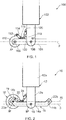
- FIG. 1 illustrates a known aircraft landing gear assembly generally at 100.
- the landing gear assembly 100 includes a main strut 102 which is movably coupled to an aircraft (not shown).
- the main strut 102 is a shock absorbing strut, but could be rigid.
- a bogie beam 104 is pivotally mounted at a lower end of the main strut 102 via a pivot pin 106.
- the bogie pivot axis BP is in the same plane P as the axle pivot axes AP, or can be slightly above it.
- the bogie beam 104 carries fore and aft axles 108 for mounting wheel assemblies (not shown). The aft axle has been omitted for clarity.
- Each wheel assembly is provided with a brake assembly 110 arranged to apply a brake torque to the wheel assembly to slow the aircraft.
- Each brake assembly 110 includes a lug 112 attached to one end of a respective brake rod 114. The other end of each brake rod 114 is attached to a respective mounting lug 116 on the top surface of the bogie beam 104.
- the landing gear assembly is a bogie anchored landing gear assembly.
- a compensating actuator 118 is provided between the main strut 102 and bogie beam 104 to apply a compensating force to the bogie beam 104 during braking.
- the compensating actuator 118 is coupled between a strut mounting lug 120 and a bogie beam mounting lug 122.
- the present inventors have identified that the weight of known landing gear can be reduced.
- FIG. 2 is a diagram of part of an aircraft; more specifically, an aircraft landing gear assembly 10 according to an embodiment of the invention.
- the aircraft landing gear assembly 10 includes a main strut 12 which is movably coupled to the airframe (not shown).
- the main strut 102 is a conventional shock absorbing strut, having an upper cylinder 12a within which a slower tube 12b is slidably mounted.
- the main strut could be rigid.
- a bogie beam 14 is pivotally mounted at a lower end of the sliding tube 12b via a pivot pin 16 located midway along the bogie beam 14.
- the bogie beam 14 has an elongate, central body portion 14a which is generally straight.
- the bogie beam 14 has raised end portions 14b which project upwardly and away from the central body portion 14a at an angle of approximately 45°.
- the end portions can take any suitable configuration; for example, the end portions 14b can extend away from the body portion 14a on the same side of the bogie beam 14 but in opposite directions at an angle of between 20° and 70°.
- Each end portion 14b is arranged to support a wheel axle 22.
- Wheel assemblies 18 are mounted on the axle 22.
- the brake assembly 19 of each wheel assembly 18 is connected to the bogie beam 14 via a brake rod 20 such that the landing gear assembly is a bogie anchored landing gear assembly.
- the landing gear assembly 10 includes a bogie beam having upturned end regions 14b which mount the wheel axles 18 above the bogie pivot pin 16. More specifically, a plane P2 which intersects the axle pivot axis AP of each axle 22 is above and spaced from a parallel plane P which intersects the bogie pivot axis BP.
- This arrangement reduces the pitching moment on the bogie beam 14 which arises due to braking. As such, this arrangement can reduce the load required from a compensating actuator 24, meaning that a smaller, lighter compensating actuator 24 can be provided.
- the specific shape of the bogie beam is not important providing it is arranged to position of the axles above the pivot pin in order to reduce the vertical distance between the tyre/ground contact point and the pivot pin. It is preferred that the bogie beam has a wave like or serpentine shape to avoid sharp corners.
- FIG. 3 shows an aircraft landing gear assembly according to a further embodiment of the invention generally at 30.
- the aircraft landing gear assembly 30 is similar to the aircraft landing gear assembly 10 and for brevity the following description will focus on the differences.
- the bogie beam 34 of the illustrated embodiment is straight so as to place the axles 38 in line with the bogie pivot pin 36.
- the bogie pivot 36 is closer to the rear axle 38a than the front axle 38b.
- vertical load static load is not evenly shared between the front and rear tyre pairs; rather, the rear tyres carry more weight than the front tyres.
- the bogie pivot pin 36 is located such that, for a specific brake torque and aircraft weight, the vertical load on the front and rear brake pairs is substantially equalised under braking.
- the vertical load and the brake torque are variable during aircraft operations. As such, no single bogie pivot pin location can ensure a constant force balance under braking. However, the offset configuration of the illustrated embodiment can nevertheless minimise the size of compensation actuator required in order to correct for variations.
- the compensation actuator 40 of the illustrated embodiment is a dual acting actuator that can be driven to extend or contract. As such, the compensation actuator 40 can apply a push force or a pull force between the main strut 32 and the bogie beam 34.
- the actuator 40 When braking is not occurring, the actuator 40 is controlled to push the bogie beam 40 to achieve a nominally even distribution of load between the front wheel assembly 42 and the back wheel assembly (not shown).
- the compensating actuator 40 can be controlled to pull the bogie beam 34 in order to compensate for the additional load on the front wheel assembly 42.
- a suitable control program can be executed by a controller located within the aircraft, or mounted on the landing gear assembly.
- This control system can control operation of the compensation actuator 40 dynamically based on measured or estimated brake torque and taking the instantaneous flight phase into account.
- a compensation actuator 40 can provide significant forces, it can be used to further reduce the weight of the landing gear by reducing cornering loads.
- the actuator at zero load, the vertical load of the aircraft would be taken predominantly by the rear tyre pair, the actuator can be scheduled to pull during turning manoeuvres (by relating the nose wheel steering angle to the amount of pull demanded). In extreme turning cases, this will have the effect of reducing the apparent vertical load on the forward tyres, hence reducing the friction force at the interface with the ground, and reducing the total turning torque load imparted to the landing gear.
- this torque is a significant design driver for bogie landing gears, the structure can be reduced in weight.
- the actuator can be employed to perform tasks well known in the art: positioning the bogie in flight for stowage or landing as well as biasing the bogie in one direction during take-off (controlled articulation).
- the actuator can be scheduled in flight to align the bogie to the airflow, using the aircraft angle from the on-board aircraft system as an input to the bogie pitch-trimmer control system. It has been shown that aligning the bogie to the airflow direction can significantly reduce the radiated aero-acoustic noise of the landing gear.
- FIG. 4 shows an aircraft landing gear assembly according to a further embodiment generally at 50.
- the aircraft landing gear assembly 50 combines both the bogie beam 14 of the embodiment described with reference to Figure 2 with the offset pivot pin 36 of the embodiment described with reference to Figure 3 , thereby combining the weight saving capabilities of the two arrangements.
- Redundancy can be built into the compensation systems through various means known in the art and typically employed on flight control actuators: two parallel compensating actuators could be employed, each powered by a separate electrical and/or hydraulic circuit and control system or a single actuator could be used with two independent pistons driven by independent hydraulic circuits.
- the choice will depend on the aircraft architecture and the volume available; two parallel actuators would typically be placed side by side, although it would be possible to position two different actuators fore and aft, whereas an architecture with two separate pistons/chambers acting on the same rod would be longer than a single actuator and may not fit in the space available.
- the actuators are sized to ensure between 50% and complete compensation in the event of a failure of one actuator/system.
- FIG. 5 shows an aircraft landing gear assembly 60 according to a further embodiment of the invention.
- the aircraft landing gear assembly 60 is similar to the landing gear assembly of FIG. 4 and for brevity the following descripting will focus on the differences.
- the landing gear assembly 60 includes first and second bogie beams 64a, 64b arranged to be mounted in a parallel side by side relationship.
- the bogie beams 64a, 64b each include identical pivot bearings arranged to receive a common bogie pivot pin 66, or coaxial bogie pivot pins, so that the bogie beams 64a, 64b pivot about a common bogie pivot axis M.
- the first bogie beam 64a includes a conventional mounting bushing by which a first axle 68a is mounted.
- the second bogie beam 64b includes a corresponding mounting bushing which carries a third axle 68c.
- the first and third axles 68a, 68c are aligned with a common axis when the bogie beams 64a, 64b are aligned in registration with one another i.e. in the same plane.
- a second end of the first bogie beam 64a includes a conventional mounting bushing which mounts a second axle 68b and the second end of the second bogie beam 64b includes a conventional mounting bushing which mounts a fourth axle 68d.
- Each axle 68a-d is arranged to mount a single wheel assembly.
- a first compensating actuator 70a is provided between the main strut 62 and first bogie beam 64a to apply a compensating force to the first bogie beam 64a during braking.
- a second compensating actuator 70b is provided between the main strut 62 and second bogie beam 64b to apply a compensating force to the second bogie beam 64b during braking.
- each bogie has a compensating actuator sized to manage the torque generated by two brakes.
- two parallel bogie beams are provided in a 'dual bicycle' arrangement in which the bogie beams can pivot about their mounting axes independently.
- Such an arrangement provides braking compensation redundancy by having a pair of independently operable compensating actuators acting on distinct bogie beams.
- the brakes and compensating actuator on the inboard bogie can be controlled and powered by one system, and the brakes and compensation on the outboard controlled by a second, independent system. In the event of a failure of one system, the other is therefore isolated and unaffected.
- This arrangement is also advantageous over an arrangement in which redundancy is provided by a pair of actuators acting on a common bogie beam because each actuator need only be sized to compensate for pitching moment induced by the brake assemblies on one side of the landing gear assembly, which can provide a weight advantage.
- the landing gear assembly 60 can have just one of the relatively low bogie pivot axis of the embodiment described with reference to Figure 2 and the offset pivot pin 36 of the embodiment described with reference to Figure 3 .
- the landing gear assemblies of the illustrated embodiments have brake assemblies coupled to the bogie beams by brake rods
- the brake assemblies can be rotationally fixed relative to the bogie beam by any suitable means such as splines or a flange on the axle, or any other mechanism where the brake is fixed rigidly to the axle and/or bogie beam so as to cause a pitching moment on the bogie under braking which is greater than the pitching moment created in a conventional arrangement where the brake rods are arranged parallel and offset with respect to the bogie to provide force cancellation during braking.
- Landing gear assemblies according to embodiments of the invention can be formed of conventional aerospace materials, such as stainless steel, aluminium or titanium.
- Landing gear assemblies according to embodiments of the invention can be main landing gear assemblies for medium to large aircrafts.
Landscapes
- Engineering & Computer Science (AREA)
- Mechanical Engineering (AREA)
- Aviation & Aerospace Engineering (AREA)
- Regulating Braking Force (AREA)
- Retarders (AREA)
- Braking Systems And Boosters (AREA)
- Braking Arrangements (AREA)
- Gear Transmission (AREA)
Priority Applications (7)
| Application Number | Priority Date | Filing Date | Title |
|---|---|---|---|
| EP20177985.7A EP3722205B1 (de) | 2017-04-20 | 2017-04-20 | Flugzeugfahrwerksbaugruppe |
| ES20177985T ES2906230T3 (es) | 2017-04-20 | 2017-04-20 | Conjunto de tren de aterrizaje de aeronave |
| EP17167352.8A EP3392139B1 (de) | 2017-04-20 | 2017-04-20 | Flugzeugfahrwerksbaugruppe |
| CN201810307116.8A CN108725760B (zh) | 2017-04-20 | 2018-04-08 | 飞行器起落架组件 |
| US15/950,701 US11059571B2 (en) | 2017-04-20 | 2018-04-11 | Aircraft landing gear assembly |
| CA3002051A CA3002051C (en) | 2017-04-20 | 2018-04-17 | Aircraft landing gear assembly |
| CA3212420A CA3212420C (en) | 2017-04-20 | 2018-04-17 | Aircraft landing gear assembly |
Applications Claiming Priority (1)
| Application Number | Priority Date | Filing Date | Title |
|---|---|---|---|
| EP17167352.8A EP3392139B1 (de) | 2017-04-20 | 2017-04-20 | Flugzeugfahrwerksbaugruppe |
Related Child Applications (2)
| Application Number | Title | Priority Date | Filing Date |
|---|---|---|---|
| EP20177985.7A Division EP3722205B1 (de) | 2017-04-20 | 2017-04-20 | Flugzeugfahrwerksbaugruppe |
| EP20177985.7A Division-Into EP3722205B1 (de) | 2017-04-20 | 2017-04-20 | Flugzeugfahrwerksbaugruppe |
Publications (2)
| Publication Number | Publication Date |
|---|---|
| EP3392139A1 true EP3392139A1 (de) | 2018-10-24 |
| EP3392139B1 EP3392139B1 (de) | 2020-08-26 |
Family
ID=58579092
Family Applications (2)
| Application Number | Title | Priority Date | Filing Date |
|---|---|---|---|
| EP20177985.7A Active EP3722205B1 (de) | 2017-04-20 | 2017-04-20 | Flugzeugfahrwerksbaugruppe |
| EP17167352.8A Active EP3392139B1 (de) | 2017-04-20 | 2017-04-20 | Flugzeugfahrwerksbaugruppe |
Family Applications Before (1)
| Application Number | Title | Priority Date | Filing Date |
|---|---|---|---|
| EP20177985.7A Active EP3722205B1 (de) | 2017-04-20 | 2017-04-20 | Flugzeugfahrwerksbaugruppe |
Country Status (5)
| Country | Link |
|---|---|
| US (1) | US11059571B2 (de) |
| EP (2) | EP3722205B1 (de) |
| CN (1) | CN108725760B (de) |
| CA (2) | CA3002051C (de) |
| ES (1) | ES2906230T3 (de) |
Families Citing this family (10)
| Publication number | Priority date | Publication date | Assignee | Title |
|---|---|---|---|---|
| FR3072943B1 (fr) * | 2017-10-27 | 2021-12-10 | Safran Landing Systems | Atterrisseur d'aeronef a roues freinees et roues motorisees |
| US11390380B2 (en) * | 2019-10-10 | 2022-07-19 | The Boeing Company | System and method for alleviating structural loads on a pivoting main landing gear of an aircraft in a pivot turn maneuver |
| US11136112B2 (en) * | 2020-01-02 | 2021-10-05 | The Boeing Company | Aircraft landing gear forward trunnion support assemblies, trunnion housings and related methods |
| GB2602150A (en) * | 2020-12-21 | 2022-06-22 | Airbus Operations Ltd | An aircraft landing gear |
| GB2605160B (en) * | 2021-03-24 | 2023-05-31 | Safran Landing Systems Uk Ltd | Aircraft landing gear torque link assembly |
| CN113602486B (zh) * | 2021-08-27 | 2023-03-10 | 中国商用飞机有限责任公司 | 小车式起落架及飞行器 |
| US12054282B2 (en) * | 2022-05-23 | 2024-08-06 | Safran Landing Systems Canada Inc. | Landing gear load detection system |
| CN115196000A (zh) * | 2022-07-15 | 2022-10-18 | 中国商用飞机有限责任公司 | 具有转向装置的起落架和具有起落架的飞机 |
| US20240367781A1 (en) * | 2023-05-01 | 2024-11-07 | Boom Technology, Inc. | Aircraft wheel and brake assembly |
| WO2026061605A1 (en) * | 2024-09-17 | 2026-03-26 | Safran Landing Systems | Landing gear with adjustable tire camber |
Citations (4)
| Publication number | Priority date | Publication date | Assignee | Title |
|---|---|---|---|---|
| FR1037210A (fr) * | 1951-05-17 | 1953-09-15 | Sncaso | Perfectionnement aux trains de roulement à roues multiples du type tandem ou boggie |
| US2750134A (en) * | 1952-04-17 | 1956-06-12 | Lockheed Aircraft Corp | Multiple wheel main landing gear |
| GB932731A (en) * | 1960-08-24 | 1963-07-31 | Cleveland Pneumatic Ind Inc | Aircraft landing gear |
| GB1006522A (en) * | 1963-10-08 | 1965-10-06 | Electro Hydraulics Ltd | Retractable undercarriages for aircraft |
Family Cites Families (13)
| Publication number | Priority date | Publication date | Assignee | Title |
|---|---|---|---|---|
| US3091418A (en) * | 1960-04-26 | 1963-05-28 | Dowty Rotol Ltd | Aircraft alighting gear |
| US4328939A (en) * | 1979-12-26 | 1982-05-11 | The Boeing Company | Airplane main landing gear assembly |
| US5110068A (en) * | 1990-12-20 | 1992-05-05 | The Boeing Company | Multi-axled propped landing gear |
| US6032090A (en) * | 1997-05-06 | 2000-02-29 | General Electrodynamics Corporation | System and method for on-board determination of aircraft weight and load-related characteristics |
| US6182925B1 (en) * | 1999-03-30 | 2001-02-06 | The Boeing Company | Semi-levered landing gear and auxiliary strut therefor |
| GB2428650B (en) * | 2005-08-04 | 2011-01-12 | Messier Dowty Ltd | Landing gear |
| GB2477127B (en) * | 2010-01-22 | 2016-08-31 | Messier-Dowty Ltd | Landing gear |
| US8448900B2 (en) * | 2010-03-24 | 2013-05-28 | The Boeing Company | Semi-levered landing gear and associated method |
| GB2483472B (en) * | 2010-09-08 | 2012-08-15 | Messier Dowty Ltd | Aircraft landing gear |
| US9481452B2 (en) * | 2010-11-22 | 2016-11-01 | The Boeing Company | Hydraulic actuator for semi levered landing gear |
| EP3064432B1 (de) * | 2015-03-05 | 2017-08-09 | Safran Landing Systems UK Limited | Flugzeugfahrwerkanordnung |
| GB2563945A (en) * | 2017-06-30 | 2019-01-02 | Airbus Operations Ltd | Aircraft landing gear assembly |
| EP3670336B1 (de) * | 2018-12-20 | 2020-09-23 | Safran Landing Systems UK Limited | Flugzeugfahrwerk und neigungstrimmeranordnung |
-
2017
- 2017-04-20 ES ES20177985T patent/ES2906230T3/es active Active
- 2017-04-20 EP EP20177985.7A patent/EP3722205B1/de active Active
- 2017-04-20 EP EP17167352.8A patent/EP3392139B1/de active Active
-
2018
- 2018-04-08 CN CN201810307116.8A patent/CN108725760B/zh active Active
- 2018-04-11 US US15/950,701 patent/US11059571B2/en active Active
- 2018-04-17 CA CA3002051A patent/CA3002051C/en active Active
- 2018-04-17 CA CA3212420A patent/CA3212420C/en active Active
Patent Citations (4)
| Publication number | Priority date | Publication date | Assignee | Title |
|---|---|---|---|---|
| FR1037210A (fr) * | 1951-05-17 | 1953-09-15 | Sncaso | Perfectionnement aux trains de roulement à roues multiples du type tandem ou boggie |
| US2750134A (en) * | 1952-04-17 | 1956-06-12 | Lockheed Aircraft Corp | Multiple wheel main landing gear |
| GB932731A (en) * | 1960-08-24 | 1963-07-31 | Cleveland Pneumatic Ind Inc | Aircraft landing gear |
| GB1006522A (en) * | 1963-10-08 | 1965-10-06 | Electro Hydraulics Ltd | Retractable undercarriages for aircraft |
Also Published As
| Publication number | Publication date |
|---|---|
| CN108725760A (zh) | 2018-11-02 |
| EP3722205A1 (de) | 2020-10-14 |
| US11059571B2 (en) | 2021-07-13 |
| CA3212420C (en) | 2024-04-30 |
| ES2906230T3 (es) | 2022-04-13 |
| CN108725760B (zh) | 2023-04-28 |
| US20180304999A1 (en) | 2018-10-25 |
| CA3212420A1 (en) | 2018-10-20 |
| EP3722205B1 (de) | 2022-01-12 |
| CA3002051C (en) | 2023-10-24 |
| CA3002051A1 (en) | 2018-10-20 |
| EP3392139B1 (de) | 2020-08-26 |
Similar Documents
| Publication | Publication Date | Title |
|---|---|---|
| CA3002051C (en) | Aircraft landing gear assembly | |
| EP0031601B1 (de) | Am Flugzeugrumpf angelenktes Hauptlandefahrwerk | |
| US8136759B2 (en) | Retractable articulated landing gear | |
| KR100790530B1 (ko) | 기수측 보조 착륙장치, 힘 전달 구조체, 및 회전익 항공기 | |
| US7963481B2 (en) | Method and device for supporting the take-off rotation of an aircraft | |
| US7413140B2 (en) | Rotary wing aircraft with undercarriage structure | |
| US12122506B2 (en) | Aircraft having outrigger landing gear | |
| US20210253228A1 (en) | Modular landing gear | |
| US20170355452A1 (en) | Aircraft landing gear, aircraft carrying such and methods | |
| CN101304919B (zh) | 飞机以及在地面上使飞机制动地枢转转弯的方法 | |
| GB2592204A (en) | Modular landing gear |
Legal Events
| Date | Code | Title | Description |
|---|---|---|---|
| PUAI | Public reference made under article 153(3) epc to a published international application that has entered the european phase |
Free format text: ORIGINAL CODE: 0009012 |
|
| STAA | Information on the status of an ep patent application or granted ep patent |
Free format text: STATUS: THE APPLICATION HAS BEEN PUBLISHED |
|
| AK | Designated contracting states |
Kind code of ref document: A1 Designated state(s): AL AT BE BG CH CY CZ DE DK EE ES FI FR GB GR HR HU IE IS IT LI LT LU LV MC MK MT NL NO PL PT RO RS SE SI SK SM TR |
|
| AX | Request for extension of the european patent |
Extension state: BA ME |
|
| STAA | Information on the status of an ep patent application or granted ep patent |
Free format text: STATUS: REQUEST FOR EXAMINATION WAS MADE |
|
| 17P | Request for examination filed |
Effective date: 20190415 |
|
| RBV | Designated contracting states (corrected) |
Designated state(s): AL AT BE BG CH CY CZ DE DK EE ES FI FR GB GR HR HU IE IS IT LI LT LU LV MC MK MT NL NO PL PT RO RS SE SI SK SM TR |
|
| STAA | Information on the status of an ep patent application or granted ep patent |
Free format text: STATUS: EXAMINATION IS IN PROGRESS |
|
| 17Q | First examination report despatched |
Effective date: 20190729 |
|
| REG | Reference to a national code |
Ref country code: DE Ref legal event code: R079 Ref document number: 602017022232 Country of ref document: DE Free format text: PREVIOUS MAIN CLASS: B64C0025420000 Ipc: B64C0025000000 |
|
| RIC1 | Information provided on ipc code assigned before grant |
Ipc: B64C 25/34 20060101ALI20200115BHEP Ipc: B64C 25/00 20060101AFI20200115BHEP Ipc: B64C 25/42 20060101ALI20200115BHEP |
|
| GRAP | Despatch of communication of intention to grant a patent |
Free format text: ORIGINAL CODE: EPIDOSNIGR1 |
|
| STAA | Information on the status of an ep patent application or granted ep patent |
Free format text: STATUS: GRANT OF PATENT IS INTENDED |
|
| INTG | Intention to grant announced |
Effective date: 20200311 |
|
| GRAS | Grant fee paid |
Free format text: ORIGINAL CODE: EPIDOSNIGR3 |
|
| GRAA | (expected) grant |
Free format text: ORIGINAL CODE: 0009210 |
|
| STAA | Information on the status of an ep patent application or granted ep patent |
Free format text: STATUS: THE PATENT HAS BEEN GRANTED |
|
| AK | Designated contracting states |
Kind code of ref document: B1 Designated state(s): AL AT BE BG CH CY CZ DE DK EE ES FI FR GB GR HR HU IE IS IT LI LT LU LV MC MK MT NL NO PL PT RO RS SE SI SK SM TR |
|
| REG | Reference to a national code |
Ref country code: GB Ref legal event code: FG4D |
|
| REG | Reference to a national code |
Ref country code: CH Ref legal event code: EP |
|
| REG | Reference to a national code |
Ref country code: AT Ref legal event code: REF Ref document number: 1306131 Country of ref document: AT Kind code of ref document: T Effective date: 20200915 |
|
| REG | Reference to a national code |
Ref country code: IE Ref legal event code: FG4D |
|
| REG | Reference to a national code |
Ref country code: DE Ref legal event code: R096 Ref document number: 602017022232 Country of ref document: DE |
|
| REG | Reference to a national code |
Ref country code: LT Ref legal event code: MG4D |
|
| PG25 | Lapsed in a contracting state [announced via postgrant information from national office to epo] |
Ref country code: NO Free format text: LAPSE BECAUSE OF FAILURE TO SUBMIT A TRANSLATION OF THE DESCRIPTION OR TO PAY THE FEE WITHIN THE PRESCRIBED TIME-LIMIT Effective date: 20201126 Ref country code: PT Free format text: LAPSE BECAUSE OF FAILURE TO SUBMIT A TRANSLATION OF THE DESCRIPTION OR TO PAY THE FEE WITHIN THE PRESCRIBED TIME-LIMIT Effective date: 20201228 Ref country code: BG Free format text: LAPSE BECAUSE OF FAILURE TO SUBMIT A TRANSLATION OF THE DESCRIPTION OR TO PAY THE FEE WITHIN THE PRESCRIBED TIME-LIMIT Effective date: 20201126 Ref country code: LT Free format text: LAPSE BECAUSE OF FAILURE TO SUBMIT A TRANSLATION OF THE DESCRIPTION OR TO PAY THE FEE WITHIN THE PRESCRIBED TIME-LIMIT Effective date: 20200826 Ref country code: HR Free format text: LAPSE BECAUSE OF FAILURE TO SUBMIT A TRANSLATION OF THE DESCRIPTION OR TO PAY THE FEE WITHIN THE PRESCRIBED TIME-LIMIT Effective date: 20200826 Ref country code: SE Free format text: LAPSE BECAUSE OF FAILURE TO SUBMIT A TRANSLATION OF THE DESCRIPTION OR TO PAY THE FEE WITHIN THE PRESCRIBED TIME-LIMIT Effective date: 20200826 Ref country code: GR Free format text: LAPSE BECAUSE OF FAILURE TO SUBMIT A TRANSLATION OF THE DESCRIPTION OR TO PAY THE FEE WITHIN THE PRESCRIBED TIME-LIMIT Effective date: 20201127 Ref country code: FI Free format text: LAPSE BECAUSE OF FAILURE TO SUBMIT A TRANSLATION OF THE DESCRIPTION OR TO PAY THE FEE WITHIN THE PRESCRIBED TIME-LIMIT Effective date: 20200826 |
|
| REG | Reference to a national code |
Ref country code: NL Ref legal event code: MP Effective date: 20200826 |
|
| REG | Reference to a national code |
Ref country code: AT Ref legal event code: MK05 Ref document number: 1306131 Country of ref document: AT Kind code of ref document: T Effective date: 20200826 |
|
| PG25 | Lapsed in a contracting state [announced via postgrant information from national office to epo] |
Ref country code: RS Free format text: LAPSE BECAUSE OF FAILURE TO SUBMIT A TRANSLATION OF THE DESCRIPTION OR TO PAY THE FEE WITHIN THE PRESCRIBED TIME-LIMIT Effective date: 20200826 Ref country code: PL Free format text: LAPSE BECAUSE OF FAILURE TO SUBMIT A TRANSLATION OF THE DESCRIPTION OR TO PAY THE FEE WITHIN THE PRESCRIBED TIME-LIMIT Effective date: 20200826 Ref country code: NL Free format text: LAPSE BECAUSE OF FAILURE TO SUBMIT A TRANSLATION OF THE DESCRIPTION OR TO PAY THE FEE WITHIN THE PRESCRIBED TIME-LIMIT Effective date: 20200826 Ref country code: LV Free format text: LAPSE BECAUSE OF FAILURE TO SUBMIT A TRANSLATION OF THE DESCRIPTION OR TO PAY THE FEE WITHIN THE PRESCRIBED TIME-LIMIT Effective date: 20200826 Ref country code: IS Free format text: LAPSE BECAUSE OF FAILURE TO SUBMIT A TRANSLATION OF THE DESCRIPTION OR TO PAY THE FEE WITHIN THE PRESCRIBED TIME-LIMIT Effective date: 20201226 |
|
| PG25 | Lapsed in a contracting state [announced via postgrant information from national office to epo] |
Ref country code: SM Free format text: LAPSE BECAUSE OF FAILURE TO SUBMIT A TRANSLATION OF THE DESCRIPTION OR TO PAY THE FEE WITHIN THE PRESCRIBED TIME-LIMIT Effective date: 20200826 Ref country code: EE Free format text: LAPSE BECAUSE OF FAILURE TO SUBMIT A TRANSLATION OF THE DESCRIPTION OR TO PAY THE FEE WITHIN THE PRESCRIBED TIME-LIMIT Effective date: 20200826 Ref country code: DK Free format text: LAPSE BECAUSE OF FAILURE TO SUBMIT A TRANSLATION OF THE DESCRIPTION OR TO PAY THE FEE WITHIN THE PRESCRIBED TIME-LIMIT Effective date: 20200826 Ref country code: CZ Free format text: LAPSE BECAUSE OF FAILURE TO SUBMIT A TRANSLATION OF THE DESCRIPTION OR TO PAY THE FEE WITHIN THE PRESCRIBED TIME-LIMIT Effective date: 20200826 Ref country code: RO Free format text: LAPSE BECAUSE OF FAILURE TO SUBMIT A TRANSLATION OF THE DESCRIPTION OR TO PAY THE FEE WITHIN THE PRESCRIBED TIME-LIMIT Effective date: 20200826 |
|
| REG | Reference to a national code |
Ref country code: DE Ref legal event code: R097 Ref document number: 602017022232 Country of ref document: DE |
|
| PG25 | Lapsed in a contracting state [announced via postgrant information from national office to epo] |
Ref country code: AT Free format text: LAPSE BECAUSE OF FAILURE TO SUBMIT A TRANSLATION OF THE DESCRIPTION OR TO PAY THE FEE WITHIN THE PRESCRIBED TIME-LIMIT Effective date: 20200826 Ref country code: AL Free format text: LAPSE BECAUSE OF FAILURE TO SUBMIT A TRANSLATION OF THE DESCRIPTION OR TO PAY THE FEE WITHIN THE PRESCRIBED TIME-LIMIT Effective date: 20200826 Ref country code: ES Free format text: LAPSE BECAUSE OF FAILURE TO SUBMIT A TRANSLATION OF THE DESCRIPTION OR TO PAY THE FEE WITHIN THE PRESCRIBED TIME-LIMIT Effective date: 20200826 |
|
| PG25 | Lapsed in a contracting state [announced via postgrant information from national office to epo] |
Ref country code: SK Free format text: LAPSE BECAUSE OF FAILURE TO SUBMIT A TRANSLATION OF THE DESCRIPTION OR TO PAY THE FEE WITHIN THE PRESCRIBED TIME-LIMIT Effective date: 20200826 |
|
| PLBE | No opposition filed within time limit |
Free format text: ORIGINAL CODE: 0009261 |
|
| STAA | Information on the status of an ep patent application or granted ep patent |
Free format text: STATUS: NO OPPOSITION FILED WITHIN TIME LIMIT |
|
| PG25 | Lapsed in a contracting state [announced via postgrant information from national office to epo] |
Ref country code: IT Free format text: LAPSE BECAUSE OF FAILURE TO SUBMIT A TRANSLATION OF THE DESCRIPTION OR TO PAY THE FEE WITHIN THE PRESCRIBED TIME-LIMIT Effective date: 20200826 |
|
| 26N | No opposition filed |
Effective date: 20210527 |
|
| PG25 | Lapsed in a contracting state [announced via postgrant information from national office to epo] |
Ref country code: SI Free format text: LAPSE BECAUSE OF FAILURE TO SUBMIT A TRANSLATION OF THE DESCRIPTION OR TO PAY THE FEE WITHIN THE PRESCRIBED TIME-LIMIT Effective date: 20200826 |
|
| PG25 | Lapsed in a contracting state [announced via postgrant information from national office to epo] |
Ref country code: MC Free format text: LAPSE BECAUSE OF FAILURE TO SUBMIT A TRANSLATION OF THE DESCRIPTION OR TO PAY THE FEE WITHIN THE PRESCRIBED TIME-LIMIT Effective date: 20200826 |
|
| PG25 | Lapsed in a contracting state [announced via postgrant information from national office to epo] |
Ref country code: LU Free format text: LAPSE BECAUSE OF NON-PAYMENT OF DUE FEES Effective date: 20210420 |
|
| REG | Reference to a national code |
Ref country code: BE Ref legal event code: MM Effective date: 20210430 |
|
| PG25 | Lapsed in a contracting state [announced via postgrant information from national office to epo] |
Ref country code: LI Free format text: LAPSE BECAUSE OF NON-PAYMENT OF DUE FEES Effective date: 20210430 Ref country code: CH Free format text: LAPSE BECAUSE OF NON-PAYMENT OF DUE FEES Effective date: 20210430 |
|
| PG25 | Lapsed in a contracting state [announced via postgrant information from national office to epo] |
Ref country code: IE Free format text: LAPSE BECAUSE OF NON-PAYMENT OF DUE FEES Effective date: 20210420 |
|
| PG25 | Lapsed in a contracting state [announced via postgrant information from national office to epo] |
Ref country code: IS Free format text: LAPSE BECAUSE OF FAILURE TO SUBMIT A TRANSLATION OF THE DESCRIPTION OR TO PAY THE FEE WITHIN THE PRESCRIBED TIME-LIMIT Effective date: 20201226 |
|
| PG25 | Lapsed in a contracting state [announced via postgrant information from national office to epo] |
Ref country code: BE Free format text: LAPSE BECAUSE OF NON-PAYMENT OF DUE FEES Effective date: 20210430 |
|
| PG25 | Lapsed in a contracting state [announced via postgrant information from national office to epo] |
Ref country code: CY Free format text: LAPSE BECAUSE OF FAILURE TO SUBMIT A TRANSLATION OF THE DESCRIPTION OR TO PAY THE FEE WITHIN THE PRESCRIBED TIME-LIMIT Effective date: 20200826 |
|
| PG25 | Lapsed in a contracting state [announced via postgrant information from national office to epo] |
Ref country code: HU Free format text: LAPSE BECAUSE OF FAILURE TO SUBMIT A TRANSLATION OF THE DESCRIPTION OR TO PAY THE FEE WITHIN THE PRESCRIBED TIME-LIMIT; INVALID AB INITIO Effective date: 20170420 |
|
| PG25 | Lapsed in a contracting state [announced via postgrant information from national office to epo] |
Ref country code: MK Free format text: LAPSE BECAUSE OF FAILURE TO SUBMIT A TRANSLATION OF THE DESCRIPTION OR TO PAY THE FEE WITHIN THE PRESCRIBED TIME-LIMIT Effective date: 20200826 |
|
| PG25 | Lapsed in a contracting state [announced via postgrant information from national office to epo] |
Ref country code: TR Free format text: LAPSE BECAUSE OF FAILURE TO SUBMIT A TRANSLATION OF THE DESCRIPTION OR TO PAY THE FEE WITHIN THE PRESCRIBED TIME-LIMIT Effective date: 20200826 |
|
| PG25 | Lapsed in a contracting state [announced via postgrant information from national office to epo] |
Ref country code: MT Free format text: LAPSE BECAUSE OF FAILURE TO SUBMIT A TRANSLATION OF THE DESCRIPTION OR TO PAY THE FEE WITHIN THE PRESCRIBED TIME-LIMIT Effective date: 20200826 |
|
| PGFP | Annual fee paid to national office [announced via postgrant information from national office to epo] |
Ref country code: DE Payment date: 20250417 Year of fee payment: 9 |
|
| PGFP | Annual fee paid to national office [announced via postgrant information from national office to epo] |
Ref country code: FR Payment date: 20250422 Year of fee payment: 9 |
|
| PGFP | Annual fee paid to national office [announced via postgrant information from national office to epo] |
Ref country code: GB Payment date: 20260327 Year of fee payment: 10 |