EP3395533A1 - Moule pour un moulage par injection d'une roue et procédé de moulage par injection d'une roue - Google Patents
Moule pour un moulage par injection d'une roue et procédé de moulage par injection d'une roue Download PDFInfo
- Publication number
- EP3395533A1 EP3395533A1 EP16878657.2A EP16878657A EP3395533A1 EP 3395533 A1 EP3395533 A1 EP 3395533A1 EP 16878657 A EP16878657 A EP 16878657A EP 3395533 A1 EP3395533 A1 EP 3395533A1
- Authority
- EP
- European Patent Office
- Prior art keywords
- mold
- impeller
- cavity
- movable
- side mold
- Prior art date
- Legal status (The legal status is an assumption and is not a legal conclusion. Google has not performed a legal analysis and makes no representation as to the accuracy of the status listed.)
- Withdrawn
Links
- 238000001746 injection moulding Methods 0.000 title claims abstract description 56
- 238000000034 method Methods 0.000 title 1
- 239000011347 resin Substances 0.000 claims description 23
- 229920005989 resin Polymers 0.000 claims description 23
- 238000000465 moulding Methods 0.000 claims description 18
- 239000000243 solution Substances 0.000 abstract description 2
- 238000004519 manufacturing process Methods 0.000 description 8
- 238000004080 punching Methods 0.000 description 6
- 230000002093 peripheral effect Effects 0.000 description 4
- 229920000049 Carbon (fiber) Polymers 0.000 description 2
- 239000004917 carbon fiber Substances 0.000 description 2
- 230000000694 effects Effects 0.000 description 2
- VNWKTOKETHGBQD-UHFFFAOYSA-N methane Chemical compound C VNWKTOKETHGBQD-UHFFFAOYSA-N 0.000 description 2
- 238000000926 separation method Methods 0.000 description 2
- 239000004696 Poly ether ether ketone Substances 0.000 description 1
- JUPQTSLXMOCDHR-UHFFFAOYSA-N benzene-1,4-diol;bis(4-fluorophenyl)methanone Chemical compound OC1=CC=C(O)C=C1.C1=CC(F)=CC=C1C(=O)C1=CC=C(F)C=C1 JUPQTSLXMOCDHR-UHFFFAOYSA-N 0.000 description 1
- 230000008602 contraction Effects 0.000 description 1
- 239000012530 fluid Substances 0.000 description 1
- 230000013011 mating Effects 0.000 description 1
- 238000005498 polishing Methods 0.000 description 1
- 229920002530 polyetherether ketone Polymers 0.000 description 1
Images

Classifications
-
- B—PERFORMING OPERATIONS; TRANSPORTING
- B29—WORKING OF PLASTICS; WORKING OF SUBSTANCES IN A PLASTIC STATE IN GENERAL
- B29C—SHAPING OR JOINING OF PLASTICS; SHAPING OF MATERIAL IN A PLASTIC STATE, NOT OTHERWISE PROVIDED FOR; AFTER-TREATMENT OF THE SHAPED PRODUCTS, e.g. REPAIRING
- B29C45/00—Injection moulding, i.e. forcing the required volume of moulding material through a nozzle into a closed mould; Apparatus therefor
- B29C45/17—Component parts, details or accessories; Auxiliary operations
- B29C45/40—Removing or ejecting moulded articles
- B29C45/44—Removing or ejecting moulded articles for undercut articles
-
- B—PERFORMING OPERATIONS; TRANSPORTING
- B29—WORKING OF PLASTICS; WORKING OF SUBSTANCES IN A PLASTIC STATE IN GENERAL
- B29C—SHAPING OR JOINING OF PLASTICS; SHAPING OF MATERIAL IN A PLASTIC STATE, NOT OTHERWISE PROVIDED FOR; AFTER-TREATMENT OF THE SHAPED PRODUCTS, e.g. REPAIRING
- B29C45/00—Injection moulding, i.e. forcing the required volume of moulding material through a nozzle into a closed mould; Apparatus therefor
- B29C45/0025—Preventing defects on the moulded article, e.g. weld lines, shrinkage marks
-
- B—PERFORMING OPERATIONS; TRANSPORTING
- B29—WORKING OF PLASTICS; WORKING OF SUBSTANCES IN A PLASTIC STATE IN GENERAL
- B29C—SHAPING OR JOINING OF PLASTICS; SHAPING OF MATERIAL IN A PLASTIC STATE, NOT OTHERWISE PROVIDED FOR; AFTER-TREATMENT OF THE SHAPED PRODUCTS, e.g. REPAIRING
- B29C45/00—Injection moulding, i.e. forcing the required volume of moulding material through a nozzle into a closed mould; Apparatus therefor
- B29C45/17—Component parts, details or accessories; Auxiliary operations
- B29C45/26—Moulds
-
- B—PERFORMING OPERATIONS; TRANSPORTING
- B29—WORKING OF PLASTICS; WORKING OF SUBSTANCES IN A PLASTIC STATE IN GENERAL
- B29C—SHAPING OR JOINING OF PLASTICS; SHAPING OF MATERIAL IN A PLASTIC STATE, NOT OTHERWISE PROVIDED FOR; AFTER-TREATMENT OF THE SHAPED PRODUCTS, e.g. REPAIRING
- B29C45/00—Injection moulding, i.e. forcing the required volume of moulding material through a nozzle into a closed mould; Apparatus therefor
- B29C45/17—Component parts, details or accessories; Auxiliary operations
- B29C45/26—Moulds
- B29C45/2602—Mould construction elements
-
- B—PERFORMING OPERATIONS; TRANSPORTING
- B29—WORKING OF PLASTICS; WORKING OF SUBSTANCES IN A PLASTIC STATE IN GENERAL
- B29C—SHAPING OR JOINING OF PLASTICS; SHAPING OF MATERIAL IN A PLASTIC STATE, NOT OTHERWISE PROVIDED FOR; AFTER-TREATMENT OF THE SHAPED PRODUCTS, e.g. REPAIRING
- B29C45/00—Injection moulding, i.e. forcing the required volume of moulding material through a nozzle into a closed mould; Apparatus therefor
- B29C45/17—Component parts, details or accessories; Auxiliary operations
- B29C45/26—Moulds
- B29C45/2681—Moulds with rotatable mould parts
-
- F—MECHANICAL ENGINEERING; LIGHTING; HEATING; WEAPONS; BLASTING
- F04—POSITIVE - DISPLACEMENT MACHINES FOR LIQUIDS; PUMPS FOR LIQUIDS OR ELASTIC FLUIDS
- F04D—NON-POSITIVE-DISPLACEMENT PUMPS
- F04D29/00—Details, component parts, or accessories
- F04D29/02—Selection of particular materials
- F04D29/023—Selection of particular materials especially adapted for elastic fluid pumps
-
- F—MECHANICAL ENGINEERING; LIGHTING; HEATING; WEAPONS; BLASTING
- F04—POSITIVE - DISPLACEMENT MACHINES FOR LIQUIDS; PUMPS FOR LIQUIDS OR ELASTIC FLUIDS
- F04D—NON-POSITIVE-DISPLACEMENT PUMPS
- F04D29/00—Details, component parts, or accessories
- F04D29/26—Rotors specially for elastic fluids
- F04D29/28—Rotors specially for elastic fluids for centrifugal or helico-centrifugal pumps for radial-flow or helico-centrifugal pumps
- F04D29/284—Rotors specially for elastic fluids for centrifugal or helico-centrifugal pumps for radial-flow or helico-centrifugal pumps for compressors
-
- B—PERFORMING OPERATIONS; TRANSPORTING
- B29—WORKING OF PLASTICS; WORKING OF SUBSTANCES IN A PLASTIC STATE IN GENERAL
- B29C—SHAPING OR JOINING OF PLASTICS; SHAPING OF MATERIAL IN A PLASTIC STATE, NOT OTHERWISE PROVIDED FOR; AFTER-TREATMENT OF THE SHAPED PRODUCTS, e.g. REPAIRING
- B29C45/00—Injection moulding, i.e. forcing the required volume of moulding material through a nozzle into a closed mould; Apparatus therefor
- B29C45/0025—Preventing defects on the moulded article, e.g. weld lines, shrinkage marks
- B29C2045/0034—Mould parting lines
-
- B—PERFORMING OPERATIONS; TRANSPORTING
- B29—WORKING OF PLASTICS; WORKING OF SUBSTANCES IN A PLASTIC STATE IN GENERAL
- B29C—SHAPING OR JOINING OF PLASTICS; SHAPING OF MATERIAL IN A PLASTIC STATE, NOT OTHERWISE PROVIDED FOR; AFTER-TREATMENT OF THE SHAPED PRODUCTS, e.g. REPAIRING
- B29C45/00—Injection moulding, i.e. forcing the required volume of moulding material through a nozzle into a closed mould; Apparatus therefor
- B29C45/17—Component parts, details or accessories; Auxiliary operations
- B29C45/40—Removing or ejecting moulded articles
- B29C45/44—Removing or ejecting moulded articles for undercut articles
- B29C2045/4492—Removing or ejecting moulded articles for undercut articles preventing damage or deformation of undercut articles during ejection
-
- B—PERFORMING OPERATIONS; TRANSPORTING
- B29—WORKING OF PLASTICS; WORKING OF SUBSTANCES IN A PLASTIC STATE IN GENERAL
- B29L—INDEXING SCHEME ASSOCIATED WITH SUBCLASS B29C, RELATING TO PARTICULAR ARTICLES
- B29L2031/00—Other particular articles
- B29L2031/08—Blades for rotors, stators, fans, turbines or the like, e.g. screw propellers
-
- F—MECHANICAL ENGINEERING; LIGHTING; HEATING; WEAPONS; BLASTING
- F05—INDEXING SCHEMES RELATING TO ENGINES OR PUMPS IN VARIOUS SUBCLASSES OF CLASSES F01-F04
- F05D—INDEXING SCHEME FOR ASPECTS RELATING TO NON-POSITIVE-DISPLACEMENT MACHINES OR ENGINES, GAS-TURBINES OR JET-PROPULSION PLANTS
- F05D2220/00—Application
- F05D2220/40—Application in turbochargers
Definitions
- the present invention relates to an injection molding mold of an impeller and an injection molding method of the impeller that ensure reduction in a production cost of the impeller.
- An impeller made of resin is formed such that a molten resin is injected into a mold cavity, and then, the molten resin injected into the mold cavity cools and hardens to be taken out from the mold cavity.
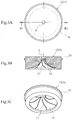
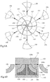
- FIG. 6 is a view illustrating an injection molding mold 101 of such an impeller 100.
- FIG. 6A is a plan view of a second mold 103 illustrated by removing a first mold 102.
- FIG. 6B is a vertical cross-sectional view of the injection molding mold 101.
- a cavity 105 is formed on a mold mating surface 104 side of the first mold 102 and the second mold 103, a plurality of inner pieces 106 are arranged on this cavity 105 so as to slidably move, and vanes 107 are formed of the molten resin that has flowed into clearances between the respective inner pieces 106.
- the respective inner pieces 106 are slid and moved to an outside in a radial direction of the impeller 100 after the first mold 102 separates from the second mold 103 (after mold opening).
- the respective inner pieces 106 are separated from the impeller 100 to ensure the separation of the impeller 100 and the second mold 103 (see Patent Document 1).
- Patent Document 1 Japanese Unexamined Utility Model Application Publication No. 1-76525 (especially, see description on 11th to 18th lines in the fourth page)
- the present invention provides an injection molding mold of an impeller and an injection molding method of the impeller that can prevent burrs from occurring on a surface of a vane of the impeller and ensure reduction in a production cost needed for burr removal of the impeller.
- the present invention relates to an injection molding mold 2 of an impeller 1.
- the injection molding mold 2 of the impeller 1 according to the present invention includes a fixed-side mold 3, a movable-side mold 4, and a cavity piece 5 arranged between these fixed-side mold 3 and movable-side mold 4. Then, at a time of mold clamping to sandwich the cavity piece 5 by the fixed-side mold 3 and the movable-side mold 4, a cavity 6 to shape the impeller 1 is formed on the cavity piece 5.
- a gate 7 to inject the molten resin into the cavity 6 is formed on the fixed-side mold 3.
- the cavity piece 5 includes an inner piece portion 12 on which the cavity 6 is formed, and a support piece portion 13 that turnably supports the inner piece portion 12 and is movably mounted on the fixed-side mold 3.
- the cavity piece 5 is configured to be moved along a first guide 10 to a first mold separating position together with the movable-side mold 4.
- the inner piece portion 12 is formed such that a spiral pattern groove 17 to shape a plurality of spiral pattern vanes 16 of the impeller 1 constitutes a part of the cavity 6.
- the movable-side mold 4 is separated from the cavity piece 5 at the first mold separating position to be moved to a second mold separating position along a second guide 11.
- the impeller 1 is configured to move integrally with the movable-side mold 4 to be separated from the inner piece portion 12 while turning the inner piece portion 12 such that the vane 16 slides and moves inside the spiral pattern groove 17 of the inner piece portion 12 when the movable-side mold 4 moves separately from the cavity piece 5.
- the present invention relates to an injection molding method of an impeller 1 to shape the impeller 1 by injecting the molten resin into a cavity 6 of an injection molding mold 2.
- the injection molding mold 2 includes a fixed-side mold 3, a movable-side mold 4, and a cavity piece 5 arranged between these fixed-side mold 3 and movable-side mold 4. Then, at a time of mold clamping to sandwich the cavity piece 5 by the fixed-side mold 3 and the movable-side mold 4, a cavity 6 to shape the impeller 1 is formed on the cavity piece 5.
- a gate 7 to inject the molten resin into the cavity 6 is formed on the fixed-side mold 3.
- the cavity piece 5 includes an inner piece portion 12 on which the cavity 6 is formed, and a support piece portion 13 that turnably supports the inner piece portion 12 and is movably mounted on the fixed-side mold 3. Then, the cavity piece 5 is configured to be moved along a first guide 10 to a first mold separating position together with the movable-side mold 4.
- the inner piece portion 12 is formed such that a spiral pattern groove 17 to shape a plurality of spiral pattern vanes 16 of the impeller 1 constitutes a part of the cavity 6.
- the movable-side mold 4 is configured to be separated from the cavity piece 5 at the first mold separating position to be moved to a second mold separating position along a second guide 11.
- the impeller 1 is formed through (1) a first molding step of injecting the molten resin into the cavity 6 from the gate 7, (2) a second molding step of separating the cavity piece 5 from the fixed-side mold 3 together with the movable-side mold 4 to be separated from the gate 7 after the molten resin injected into the cavity 6 is cooled to harden, and (3) a third molding step of moving the impeller 1 integrally with the movable-side mold 4 to be separated from the inner piece portion 12 while turning the inner piece portion 12 such that the vane 16 slides and moves inside the spiral pattern groove 17 of the inner piece portion 12 when the movable-side mold 4 is separated from the cavity piece 5 to be moved toward the second mold separating position.
- the present invention can prevent the burrs from occurring on the surface of the vane of the impeller, thus reducing the production cost needed for the burr removal of the impeller.
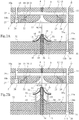
- FIG. 1 and FIG. 2 are views illustrating an injection molding mold 2 of an impeller 1 according to the embodiment of the present invention.
- FIG. 1A is a cross-sectional view of the injection molding mold 2 in a first molding step of the impeller 1.
- FIG. 1B is a cross-sectional view of the injection molding mold 2 in a second molding step of the impeller 1.
- FIG. 2A is a cross-sectional view of the injection molding mold 2 in a third molding step of the impeller 1.
- FIG. 2B is a cross-sectional view of the injection molding mold 2 illustrating an extracting step of the impeller 1.
- the injection molding mold 2 includes a fixed-side mold 3, a movable-side mold 4, and a cavity piece 5 arranged between these fixed-side mold 3 and movable-side mold 4. Then, as shown in FIG. 1A , the injection molding mold 2 is constituted such that an internal space of the cavity piece 5 becomes a cavity 6 to shape the impeller 1 at a time of mold clamping to sandwich the cavity piece 5 between the fixed-side mold 3 and the movable-side mold 4.
- a gate 7 to inject a molten resin for example, PEEK containing carbon fiber and PPS containing carbon fiber
- This gate 7, which is a pin gate formed to be positioned concentrically with a central axis 8 of the cavity 6, is configured to flow the molten resin toward an outer side in a radial direction of the cavity 6 from a center side of the cavity 6.
- a plurality of first guides 10 that guide the cavity piece 5 to move to a first mold separating position apart from the fixed-side mold 3 by a predetermined dimension are mounted around the central axis 8 on the fixed-side mold 3 (see FIG. 1B ).
- a plurality of second guides 11 that guide the movable-side mold 4 to move to a second mold separating position apart from the first mold separating position further by the predetermined dimension are mounted around the central axis 8 on the fixed-side mold 3 (see FIG. 2 ).
- Central axes of the cavity piece 5, the impeller 1, and the gate 7 are concentric with the central axis 8 of the cavity 6, and represented as the central axis 8 for convenience.
- the cavity piece 5 includes an inner piece portion 12 on which the cavity 6 is formed, and a support piece portion 13 that turnably supports the inner piece portion 12 and is movably mounted on the fixed-side mold 3. Then, this cavity piece 5 is configured to be moved along the first guide 10 and the second guide 11 to the first mold separating position together with the movable-side mold 4.
- the inner piece portion 12 has a circular shape in plan view, and a space 14 to be the cavity 6 is formed around the central axis 8.
- a plurality of spiral pattern grooves 17 (its count is identical to a count of vanes 16) to form the spiral pattern vanes 16 of the impeller 1 are formed on an inner surface of the space 14 to shape an impeller main body 15.
- These spiral pattern grooves 17 are configured to constitute a part of the cavity 6.
- this inner piece portion 12 is turnably supported to the support piece portion 13 via a bearing 18.
- This inner piece portion 12 has the circular shape in plan view, and a ring-shaped protrusion 20 is formed on an outer peripheral surface of the inner piece portion 12.
- This ring-shaped protrusion 20 of the inner piece portion 12 is configured to be sandwiched between a retainer protrusion 21 of the support piece portion 13 and the bearing 18.
- the bearing 18 is fitted to an inner peripheral surface of a bearing hole 22 of the support piece portion 13 and secured to the support piece portion 13 with a bearing securing plate 23.
- the bearing securing plate 23 has a hollow circular-plate shape and has a plurality of positions in a circumferential direction secured to the support piece portion 13 with screws 24.
- Such an inner piece portion 12 is positioned along the central axis 8 of the cavity piece 5 and turnably supported to the support piece portion 13 via the bearing 18.
- a first guide hole 25 slidably engaged with a rod portion 10a of the first guide 10 secured to the fixed-side mold 3 is formed on the support piece portion 13, and a stopper-portion engaging hole 26 that slidably houses a stopper portion 10b formed on a distal end of the rod portion 10a of the first guide 10 is formed on the support piece portion 13.
- the support piece portion 13 is configured such that the stopper-portion engaging hole 26 has a diameter larger than a diameter of the first guide hole 25, and the stopper portion 10b of the first guide 10 can be separated from the fixed-side mold 3 integrally with the inner piece portion 12 by being guided by the rod portion 10a of the first guide 10 until when being bumped against a bottom surface 27 of the stopper-portion engaging hole 26.
- a position where the stopper portion 10b of the first guide 10 is bumped against this bottom surface 27 of the stopper-portion engaging hole 26 of the support piece portion 13 will be the first mold separating position of the cavity piece 5. Then, this support piece portion 13 is held onto the first mold separating position such that the bottom surface 27 of the stopper-portion engaging hole 26 is pressed to the stopper portion 10b of the first guide 10 with a spring (not illustrated).
- the plurality of first guides 10 are arranged around the central axis 8 to be configured to smoothly slide and move the cavity piece 5.
- the stopper portion 10b of the first guide 10 has a diameter larger than a diameter of the rod portion 10a, and may be formed integrally with the rod portion 10a or may be formed separately from the rod portion 10a to be secured (for example, welded and screwed) to the rod portion 10a.
- a second guide hole 28a slidably engaged with a rod portion 11a of the second guide 11 secured to the fixed-side mold 3 is formed on the support piece portion 13.
- the plurality of second guides 11 are formed around the central axis 8 to be configured to smoothly guide move of the cavity piece 5 and the movable-side mold 4.
- the movable-side mold 4 is configured to be coupled to a driving device (not illustrated) to be guided by the second guide 11, thus smoothly moving from a mold clamping position (a position shown in FIG. 1A ) to the second mold separating position (a position shown in FIG. 2 ) and smoothly moving from the second mold separating position to the mold clamping position.
- a second guide hole 28b slidably engaged with the rod portion 11a of the second guide 11 is formed on this movable-side mold 4, and a stopper-portion engaging hole 30 that slidably houses a stopper portion 11b formed on a distal end of the rod portion 11a of the second guide 11 is formed on this movable-side mold 4.
- the stopper-portion engaging hole 30 has a diameter larger than a diameter of the second guide hole 28b, and the stopper portion 11b of the second guide 11 is configured to move guided by the rod portion 11a of the second guide 11 until when being bumped against a bottom surface 31 of the stopper-portion engaging hole 30.
- This position where the stopper portion 11b of the second guide 11 is bumped against the bottom surface 31 of the stopper-portion engaging hole 30 in the movable-side mold 4 is the second mold separating position of the injection molding mold 2, and a dimension from the fixed-side mold 3 is far away from the first mold separating position, thus being a position where the impeller 1 can be taken out from between the cavity piece 5 held onto the first mold separating position and the movable-side mold 4.
- the movable-side mold 4 is pressed to the stopper portion 11b of the second guide 11 by elastic force of the spring (not illustrated) to be held onto the second mold separating position.
- the movable-side mold 4 separates from the cavity piece 5 at the first mold separating position on the way to the second mold separating position from the mold clamping position to move to the second mold separating position integrally with the impeller 1.
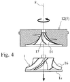
- the impeller 1 that moves integrally with this movable-side mold 4 smoothly leaves the inner piece portion 12 of the cavity piece 5 such that the spiral pattern vane 16 slides and moves inside the spiral pattern groove 17 of the inner piece portion 12 of the cavity piece 5 to turn the inner piece portion 12.
- the movable-side mold 4 includes a truncated cone shaped portion 34 bulging into a taper shape to shape a punching portion 33 on a back surface 1a side of the impeller 1, an annular recess 35 positioned radially medial to this truncated cone shaped portion 34, and a shaft mold portion 36 positioned radially medial to this annular recess 35, on a surface 32 side opposed to the cavity piece 5.
- the shaft mold portion 36 is a round-bar-shaped part centering the central axis 8 and is configured to shape a shaft hole 37 positioned on the center of the impeller 1.
- the annular recess 35 is configured to shape a cylindrically-shaped boss 38 bulging to the back surface 1a side of the impeller 1.
- the truncated cone shaped portion 34 is configured to shape the punching portion 33 having a truncated cone shape on the back surface 1a side of the impeller 1.
- an ejector sleeve 40 is arranged to slidably move on a position on an outer peripheral side of the shaft mold portion 36 and corresponding to the annular recess 35, and a plurality of ejector pins 41 are arranged around the central axis 8 to slidably move.
- a plurality of ejector pins 41 are arranged around the central axis 8 to slidably move.
- this ejector sleeve 40 disposed on the movable-side mold 4 presses the cylindrically-shaped boss 38 of the impeller 1 to a side of the cavity piece 5 to extrude the cylindrically-shaped boss 38 of the impeller 1 from the annular recess 35 of the movable-side mold 4 in a state where the movable-side mold 4 has moved to the second mold separating position. As shown in FIG.
- the ejector pin 41 disposed on the movable-side mold 4 presses near an outside end in a radial direction of the back surface 1a of the impeller 1 to the cavity piece 5 side to separate (extrude) the impeller 1 from the movable-side mold 4 in the state where the movable-side mold 4 has moved to the second mold separating position.
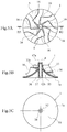
- FIG. 5 is a view illustrating the impeller 1 injection-molded with the above-described injection molding mold 2.
- FIG. 5A is a plan view of the impeller 1.
- FIG. 5B is a cross-sectional view of the impeller 1 taken along a line B2-B2 in FIG. 5A.
- FIG. 5C is a back surface view of the impeller 1.
- the impeller 1 is formed into an approximately truncated cone shape where one end side 42a (an upper end side in FIG. 5B ) along the central axis 8 (a rotation axis) has an outer diameter smaller than an outer diameter of another end side 42b (a lower end side in FIG. 5B ) along the central axis 8. Then, this impeller 1 has the impeller main body 15 having an approximately truncated cone shape, and the plurality of vanes 16 formed at regular intervals along a circumferential direction of an external surface of this impeller main body 15. In the impeller main body 15, the approximately truncated cone shaped punching portion 33 is formed on the back surface (lower end surface) 1a side.
- This punching portion 33 is formed around the central axis 8 of the impeller 1 to be positioned between the impeller main body 15 and the cylindrically-shaped boss 38, thus having an outer diameter dimension gradually increasing in a reverse taper shape from a deepest portion 33a toward the back surface 1a side.
- This punching portion 33 has a radially inward end on which the cylindrically-shaped boss 38 is formed.
- This boss 38 extends from the deepest portion 33a of the punching portion 33 to the back surface 1a along the central axis 8.
- the shaft hole 37 is formed along the central axis 8 at a center portion of the impeller main body 15.
- the shaft hole 37 is a closed-bottom hole opening to the back surface 1a side of the impeller main body 15, and a rotation shaft (not illustrated) will be fitted to the shaft hole 37.
- the vane 16 of the impeller 1 after being formed into a spiral pattern having a predetermined lead angle around the central axis 8 of the impeller 1, has a shape such that an outer peripheral surface side in the radial direction is scraped off so as to match an inner surface shape of a case (not illustrated) where the impeller 1 is housed. Then, this vane 16 of the impeller 1 is shaped with the spiral pattern groove 17 (a part of the cavity 6) engraved on the inner piece portion 12 at the time of the injection molding.
- the inner piece portion 12 is not divided by respective vanes 16 as in the conventional example, thus not having the configuration where the mold parting surfaces 108a to 108c of the inner piece 106 are positioned on the surface of the vane 107 as in the conventional example (see FIG. 6 ). Accordingly, the burrs do not occur on the surface of the vane 16.
- the impeller 1 injection-molded using the injection molding mold 2 according to the embodiment eliminates a need for a deburring work as after processing to reduce man hours in the production, thus reducing the production cost.
- the following describes an injection molding method of the impeller 1 using the injection molding mold 2 according to the embodiment with reference to FIG. 1 to FIG. 5 .
- the cavity 6 to shape the impeller 1 inside the inner piece portion 12 is formed, and the molten resin is injected into this cavity 6 from the gate 7 of the fixed-side mold 3 (a first molding step).
- the molten resin injected into the cavity 6 from the gate 7 smoothly flows from a small-diameter part side positioned on the one end side 42a along the central axis 8 of the impeller 1 to a large-diameter part side positioned on the other end side 42b along the central axis 8 of the impeller 1.
- the injection molding method of the impeller 1 improves filling-up efficiency into the cavity 6 (especially, a part to shape the vane 16), compared with, for example, a case where the gate 7 is arranged so that the molten resin flows from the large-diameter part side positioned on the other end side 42b along the central axis 8 of the impeller 1 to the small-diameter part side positioned on the one end side 42a along the central axis 8 of the impeller 1.
- the gate 7 of the injection molding mold 2 is arranged on the small-diameter part side of the one end side 42a along the central axis 8 of the impeller 1.
- the cavity piece 5 and the movable-side mold 4 are integrally separated from the fixed-side mold 3 to separate the impeller 1 inside the cavity 6 (the resin hardened in the cavity 6) from the resin inside the gate 7 (a second molding step). Then, the cavity piece 5 and the movable-side mold 4 integrally move from the mold clamping position in FIG. 1A to the first mold separating position in FIG. 1B .
- the impeller 1 made of the resin cooled and hardened inside the cavity 6 has a contraction percentage larger than those of the metallic cavity piece 5 and movable-side mold 4, thus generating a clearance between the vane 16 and the spiral pattern groove 17.
- the impeller main body 15 fastens the shaft mold portion 36 of the movable-side mold 4.
- the vane 16 of the impeller 1 is formed in the spiral pattern groove 17 of the inner piece portion 12.
- the inner piece portion 12 of the cavity piece 5 is turned by the vane 16 of the impeller 1 that moves integrally with the movable-side mold 4, thus being separated from the impeller 1 that moves integrally with the movable-side mold 4 (a third molding step).
- the embodiment as described above can prevent the burrs from occurring on the surface of the vane 16 of the impeller 1 to ensure the reduction in the production cost needed for the burr removal of the impeller 1.
- the gate 7 of the fixed-side mold 3 is exemplified as the pin gate.
- the gate 7 is not limited to this, and may be a ring gate or a multipoint gate.
Landscapes
- Engineering & Computer Science (AREA)
- Mechanical Engineering (AREA)
- Manufacturing & Machinery (AREA)
- General Engineering & Computer Science (AREA)
- Moulds For Moulding Plastics Or The Like (AREA)
Applications Claiming Priority (2)
| Application Number | Priority Date | Filing Date | Title |
|---|---|---|---|
| JP2015251152A JP6587536B2 (ja) | 2015-12-24 | 2015-12-24 | インペラの射出成形金型及びインペラの射出成形方法 |
| PCT/JP2016/087865 WO2017110768A1 (fr) | 2015-12-24 | 2016-12-20 | Moule pour un moulage par injection d'une roue et procédé de moulage par injection d'une roue |
Publications (2)
| Publication Number | Publication Date |
|---|---|
| EP3395533A1 true EP3395533A1 (fr) | 2018-10-31 |
| EP3395533A4 EP3395533A4 (fr) | 2019-08-28 |
Family
ID=59090446
Family Applications (1)
| Application Number | Title | Priority Date | Filing Date |
|---|---|---|---|
| EP16878657.2A Withdrawn EP3395533A4 (fr) | 2015-12-24 | 2016-12-20 | Moule pour un moulage par injection d'une roue et procédé de moulage par injection d'une roue |
Country Status (5)
| Country | Link |
|---|---|
| US (1) | US20180370105A1 (fr) |
| EP (1) | EP3395533A4 (fr) |
| JP (1) | JP6587536B2 (fr) |
| CN (1) | CN108367475A (fr) |
| WO (1) | WO2017110768A1 (fr) |
Cited By (2)
| Publication number | Priority date | Publication date | Assignee | Title |
|---|---|---|---|---|
| CN112810069A (zh) * | 2020-12-30 | 2021-05-18 | 陈卓然 | 一种精密度高的拼接式注塑机用模具 |
| EP4374987A4 (fr) * | 2021-06-22 | 2025-07-30 | Nikon Corp | Moule et élément de lame |
Families Citing this family (2)
| Publication number | Priority date | Publication date | Assignee | Title |
|---|---|---|---|---|
| GB2578941B (en) * | 2017-02-27 | 2022-05-11 | Mitsubishi Heavy Ind Ltd | Injection-molding machine and method of manufacturing composite material part |
| KR20240086464A (ko) * | 2022-12-09 | 2024-06-18 | 삼성전자주식회사 | 금형 장치 |
Family Cites Families (9)
| Publication number | Priority date | Publication date | Assignee | Title |
|---|---|---|---|---|
| JPH01285823A (ja) * | 1988-05-13 | 1989-11-16 | Tokico Ltd | タービンロータの製造方法 |
| JPH0642302A (ja) * | 1992-07-23 | 1994-02-15 | Nissan Motor Co Ltd | 繊維強化樹脂製インペラ |
| JP3018853B2 (ja) * | 1993-08-30 | 2000-03-13 | 日産自動車株式会社 | 繊維強化樹脂製インペラ成形体および繊維強化樹脂製インペラ成形用成形型 |
| EP1177084B1 (fr) * | 1998-12-23 | 2009-08-26 | Jetfan Technology Limited | Moule et procede pour la fabrication d'un ventilateur possedant un moyeu et plusieurs pales helicoidales s'etendant depuis ce dernier |
| JP3907887B2 (ja) * | 1999-10-28 | 2007-04-18 | 株式会社エンプラス | 円周流ポンプ用インペラ |
| CN1364688A (zh) * | 2001-01-19 | 2002-08-21 | 三菱重工业株式会社 | 螺旋桨式风扇的叶片的注射模塑成形成形法 |
| JP4746336B2 (ja) * | 2005-03-29 | 2011-08-10 | 三光合成株式会社 | 成形品の型抜き方法及び射出成形金型装置 |
| DE102006029960A1 (de) * | 2006-06-29 | 2008-01-03 | BSH Bosch und Siemens Hausgeräte GmbH | Trockner mit verringerter Geräuschentwicklung, hierfür geeignetes Gebläse und Läuferrad sowie Verfahren zur Herstellung des Läuferrades |
| US20090297344A1 (en) * | 2008-05-30 | 2009-12-03 | Controlled Power Technologies Limited | Rotors and manufacturing methods for rotors |
-
2015
- 2015-12-24 JP JP2015251152A patent/JP6587536B2/ja active Active
-
2016
- 2016-12-20 CN CN201680073407.4A patent/CN108367475A/zh active Pending
- 2016-12-20 WO PCT/JP2016/087865 patent/WO2017110768A1/fr not_active Ceased
- 2016-12-20 EP EP16878657.2A patent/EP3395533A4/fr not_active Withdrawn
- 2016-12-20 US US16/065,182 patent/US20180370105A1/en not_active Abandoned
Cited By (3)
| Publication number | Priority date | Publication date | Assignee | Title |
|---|---|---|---|---|
| CN112810069A (zh) * | 2020-12-30 | 2021-05-18 | 陈卓然 | 一种精密度高的拼接式注塑机用模具 |
| CN112810069B (zh) * | 2020-12-30 | 2022-11-29 | 武汉联镇科技有限公司 | 一种精密度高的拼接式注塑机用模具 |
| EP4374987A4 (fr) * | 2021-06-22 | 2025-07-30 | Nikon Corp | Moule et élément de lame |
Also Published As
| Publication number | Publication date |
|---|---|
| JP2017113973A (ja) | 2017-06-29 |
| WO2017110768A1 (fr) | 2017-06-29 |
| CN108367475A (zh) | 2018-08-03 |
| US20180370105A1 (en) | 2018-12-27 |
| JP6587536B2 (ja) | 2019-10-09 |
| EP3395533A4 (fr) | 2019-08-28 |
Similar Documents
| Publication | Publication Date | Title |
|---|---|---|
| EP3395533A1 (fr) | Moule pour un moulage par injection d'une roue et procédé de moulage par injection d'une roue | |
| CN101842209B (zh) | 补偿模具堆叠及用于对准的方法 | |
| CN101743108A (zh) | 补偿模具堆叠、并入有补偿模具堆叠的模制系统及对准补偿模具堆叠的方法 | |
| KR101187272B1 (ko) | 나사산이 면 맞춤으로 이루어지는 나사코어 및, 이 나사코어의 회전을 위한 스플라인 구동장치를 지닌 사출성형금형. | |
| CN110948788A (zh) | 注射成型用模具 | |
| US20090011168A1 (en) | Circular resin-molded product having circular center hole and method and apparatus for molding the same | |
| JP5081018B2 (ja) | 金型装置 | |
| JP2010042653A (ja) | コア金型 | |
| US11992983B2 (en) | Method of manufacturing resin retainer having two annular sections | |
| EP3319777B1 (fr) | Étage de moule pour machine de moulage par injection | |
| EP3527831A1 (fr) | Roue à aubes moulée par injection | |
| JPH11277583A (ja) | 羽根車の成形方法及びその装置 | |
| JP7365091B1 (ja) | インサート成形用金型部品、インサート成形用金型、及びインサート樹脂成形品の製造方法 | |
| JP6998187B2 (ja) | 中空円盤状スラストワッシャの製造方法 | |
| JP4495585B2 (ja) | 樹脂レンズの成形型 | |
| JP7057676B2 (ja) | スラストワッシャの射出成形金型 | |
| EP3342576A1 (fr) | Procédé de moulage par injection pour filtre à mailles, moule de moulage par injection et filtre à mailles | |
| US7611655B2 (en) | Molding metal mold and method for producing a molded item | |
| CN104209790B (zh) | 前置式精密液压筒夹 | |
| CN102672888A (zh) | 镜筒成型模具 | |
| JP2008201055A (ja) | 樹脂成形用金型 | |
| CN219405239U (zh) | 一种注塑模具 | |
| JP2025007257A (ja) | 金型装置 | |
| CN203019571U (zh) | 汽车注射模圆台导向定位装置 | |
| JP2006272748A (ja) | 成形品の型抜き方法及び射出成形金型装置 |
Legal Events
| Date | Code | Title | Description |
|---|---|---|---|
| STAA | Information on the status of an ep patent application or granted ep patent |
Free format text: STATUS: THE INTERNATIONAL PUBLICATION HAS BEEN MADE |
|
| PUAI | Public reference made under article 153(3) epc to a published international application that has entered the european phase |
Free format text: ORIGINAL CODE: 0009012 |
|
| STAA | Information on the status of an ep patent application or granted ep patent |
Free format text: STATUS: REQUEST FOR EXAMINATION WAS MADE |
|
| 17P | Request for examination filed |
Effective date: 20180718 |
|
| AK | Designated contracting states |
Kind code of ref document: A1 Designated state(s): AL AT BE BG CH CY CZ DE DK EE ES FI FR GB GR HR HU IE IS IT LI LT LU LV MC MK MT NL NO PL PT RO RS SE SI SK SM TR |
|
| AX | Request for extension of the european patent |
Extension state: BA ME |
|
| DAV | Request for validation of the european patent (deleted) | ||
| DAX | Request for extension of the european patent (deleted) | ||
| A4 | Supplementary search report drawn up and despatched |
Effective date: 20190725 |
|
| RIC1 | Information provided on ipc code assigned before grant |
Ipc: F04D 29/22 20060101ALI20190719BHEP Ipc: B29C 45/44 20060101ALI20190719BHEP Ipc: B29C 45/00 20060101ALI20190719BHEP Ipc: B29C 45/26 20060101AFI20190719BHEP |
|
| GRAP | Despatch of communication of intention to grant a patent |
Free format text: ORIGINAL CODE: EPIDOSNIGR1 |
|
| STAA | Information on the status of an ep patent application or granted ep patent |
Free format text: STATUS: GRANT OF PATENT IS INTENDED |
|
| RIC1 | Information provided on ipc code assigned before grant |
Ipc: B29C 45/44 20060101ALI20201218BHEP Ipc: F04D 29/22 20060101ALI20201218BHEP Ipc: B29C 45/00 20060101ALI20201218BHEP Ipc: B29C 45/26 20060101AFI20201218BHEP |
|
| INTG | Intention to grant announced |
Effective date: 20210120 |
|
| STAA | Information on the status of an ep patent application or granted ep patent |
Free format text: STATUS: THE APPLICATION IS DEEMED TO BE WITHDRAWN |
|
| 18D | Application deemed to be withdrawn |
Effective date: 20210601 |