EP3396142B1 - Abdeckung für kraftstoffrohranordnung - Google Patents
Abdeckung für kraftstoffrohranordnung Download PDFInfo
- Publication number
- EP3396142B1 EP3396142B1 EP17167736.2A EP17167736A EP3396142B1 EP 3396142 B1 EP3396142 B1 EP 3396142B1 EP 17167736 A EP17167736 A EP 17167736A EP 3396142 B1 EP3396142 B1 EP 3396142B1
- Authority
- EP
- European Patent Office
- Prior art keywords
- fuel
- fuel injection
- injection unit
- pipe
- engine
- Prior art date
- Legal status (The legal status is an assumption and is not a legal conclusion. Google has not performed a legal analysis and makes no representation as to the accuracy of the status listed.)
- Active
Links
Images



Classifications
-
- F—MECHANICAL ENGINEERING; LIGHTING; HEATING; WEAPONS; BLASTING
- F02—COMBUSTION ENGINES; HOT-GAS OR COMBUSTION-PRODUCT ENGINE PLANTS
- F02F—CYLINDERS, PISTONS OR CASINGS, FOR COMBUSTION ENGINES; ARRANGEMENTS OF SEALINGS IN COMBUSTION ENGINES
- F02F7/00—Casings, e.g. crankcases
- F02F7/0065—Shape of casings for other machine parts and purposes, e.g. utilisation purposes, safety
-
- F—MECHANICAL ENGINEERING; LIGHTING; HEATING; WEAPONS; BLASTING
- F02—COMBUSTION ENGINES; HOT-GAS OR COMBUSTION-PRODUCT ENGINE PLANTS
- F02B—INTERNAL-COMBUSTION PISTON ENGINES; COMBUSTION ENGINES IN GENERAL
- F02B37/00—Engines characterised by provision of pumps driven at least for part of the time by exhaust
-
- F—MECHANICAL ENGINEERING; LIGHTING; HEATING; WEAPONS; BLASTING
- F02—COMBUSTION ENGINES; HOT-GAS OR COMBUSTION-PRODUCT ENGINE PLANTS
- F02B—INTERNAL-COMBUSTION PISTON ENGINES; COMBUSTION ENGINES IN GENERAL
- F02B37/00—Engines characterised by provision of pumps driven at least for part of the time by exhaust
- F02B37/02—Gas passages between engine outlet and pump drive, e.g. reservoirs
-
- F—MECHANICAL ENGINEERING; LIGHTING; HEATING; WEAPONS; BLASTING
- F02—COMBUSTION ENGINES; HOT-GAS OR COMBUSTION-PRODUCT ENGINE PLANTS
- F02B—INTERNAL-COMBUSTION PISTON ENGINES; COMBUSTION ENGINES IN GENERAL
- F02B67/00—Engines characterised by the arrangement of auxiliary apparatus not being otherwise provided for, e.g. the apparatus having different functions; Driving auxiliary apparatus from engines, not otherwise provided for
- F02B67/10—Engines characterised by the arrangement of auxiliary apparatus not being otherwise provided for, e.g. the apparatus having different functions; Driving auxiliary apparatus from engines, not otherwise provided for of charging or scavenging apparatus
-
- F—MECHANICAL ENGINEERING; LIGHTING; HEATING; WEAPONS; BLASTING
- F02—COMBUSTION ENGINES; HOT-GAS OR COMBUSTION-PRODUCT ENGINE PLANTS
- F02M—SUPPLYING COMBUSTION ENGINES IN GENERAL WITH COMBUSTIBLE MIXTURES OR CONSTITUENTS THEREOF
- F02M55/00—Fuel-injection apparatus characterised by their fuel conduits or their venting means; Arrangements of conduits between fuel tank and pump F02M37/00
- F02M55/002—Arrangement of leakage or drain conduits in or from injectors
-
- F—MECHANICAL ENGINEERING; LIGHTING; HEATING; WEAPONS; BLASTING
- F02—COMBUSTION ENGINES; HOT-GAS OR COMBUSTION-PRODUCT ENGINE PLANTS
- F02M—SUPPLYING COMBUSTION ENGINES IN GENERAL WITH COMBUSTIBLE MIXTURES OR CONSTITUENTS THEREOF
- F02M55/00—Fuel-injection apparatus characterised by their fuel conduits or their venting means; Arrangements of conduits between fuel tank and pump F02M37/00
- F02M55/02—Conduits between injection pumps and injectors, e.g. conduits between pump and common-rail or conduits between common-rail and injectors
-
- F—MECHANICAL ENGINEERING; LIGHTING; HEATING; WEAPONS; BLASTING
- F02—COMBUSTION ENGINES; HOT-GAS OR COMBUSTION-PRODUCT ENGINE PLANTS
- F02M—SUPPLYING COMBUSTION ENGINES IN GENERAL WITH COMBUSTIBLE MIXTURES OR CONSTITUENTS THEREOF
- F02M55/00—Fuel-injection apparatus characterised by their fuel conduits or their venting means; Arrangements of conduits between fuel tank and pump F02M37/00
- F02M55/02—Conduits between injection pumps and injectors, e.g. conduits between pump and common-rail or conduits between common-rail and injectors
- F02M55/025—Common rails
-
- F—MECHANICAL ENGINEERING; LIGHTING; HEATING; WEAPONS; BLASTING
- F02—COMBUSTION ENGINES; HOT-GAS OR COMBUSTION-PRODUCT ENGINE PLANTS
- F02M—SUPPLYING COMBUSTION ENGINES IN GENERAL WITH COMBUSTIBLE MIXTURES OR CONSTITUENTS THEREOF
- F02M2200/00—Details of fuel-injection apparatus, not otherwise provided for
- F02M2200/16—Sealing of fuel injection apparatus not otherwise provided for
-
- F—MECHANICAL ENGINEERING; LIGHTING; HEATING; WEAPONS; BLASTING
- F02—COMBUSTION ENGINES; HOT-GAS OR COMBUSTION-PRODUCT ENGINE PLANTS
- F02M—SUPPLYING COMBUSTION ENGINES IN GENERAL WITH COMBUSTIBLE MIXTURES OR CONSTITUENTS THEREOF
- F02M2200/00—Details of fuel-injection apparatus, not otherwise provided for
- F02M2200/80—Fuel injection apparatus manufacture, repair or assembly
- F02M2200/8023—Fuel injection apparatus manufacture, repair or assembly the assembly involving use of quick-acting mechanisms, e.g. clips
-
- Y—GENERAL TAGGING OF NEW TECHNOLOGICAL DEVELOPMENTS; GENERAL TAGGING OF CROSS-SECTIONAL TECHNOLOGIES SPANNING OVER SEVERAL SECTIONS OF THE IPC; TECHNICAL SUBJECTS COVERED BY FORMER USPC CROSS-REFERENCE ART COLLECTIONS [XRACs] AND DIGESTS
- Y02—TECHNOLOGIES OR APPLICATIONS FOR MITIGATION OR ADAPTATION AGAINST CLIMATE CHANGE
- Y02T—CLIMATE CHANGE MITIGATION TECHNOLOGIES RELATED TO TRANSPORTATION
- Y02T10/00—Road transport of goods or passengers
- Y02T10/10—Internal combustion engine [ICE] based vehicles
- Y02T10/12—Improving ICE efficiencies
Definitions
- the present disclosure generally relates to a fuel pipe assembly of an engine. More particularly, the present disclosure relates to a cover for the fuel pipe assembly of the engine.
- Power producing units like internal combustion engines include one or more cylinders.
- the cylinders have a combustion chamber configured to receive fuel/air-fuel mixture i.e. charge.
- the charge is delivered to the cylinder(s) by a fuel delivery system.
- the fuel delivery system may utilize a common rail, also known as a fuel rail or common rail, to distribute fuel to fuel injectors.
- the fuel rail may include single or multiple pipes from which fuel is supplied to multiple injectors and subsequently to the cylinder of the internal combustion engine.
- Such fuel delivery systems are susceptible to leakage from the fuel rail or elsewhere in the fuel delivery system.
- EP0748934 European patent application number 0748934 (hereinafter referred to as EP0748934 ) relates to a pipe assembly for a vehicle.
- EP0748934 discloses two separate fuel pipes and a fire retardant covering.
- the fire retardant covering covers the pipes and joins the pipes by forming a web of fire retardant material which extends between the two covered pipes.
- an engine in another aspect of the present disclosure, includes a fuel injection system configured to inject fuel into a plurality of combustion chambers.
- the fuel injection system includes a first fuel injection unit and a second fuel injection unit.
- the engine further comprising a fuel pipe assembly having at least one fuel pipe fluidly coupled to the first fuel injection unit and the second fuel injection unit and a cover assembly.
- the cover assembly is disposed over the fuel pipe assembly having a U-shaped first structure having a first edge and second edge extending along a length of the first structure configured to be placed on the fuel pipe assembly and extending along a portion of a length of the fuel pipe assembly, the first structure configured to partially encapsulate the fuel pipe assembly; and a second structure, extending along the portion of the length of the fuel pipe assembly and configured to be coupled to the first structure such that the first structure and the second structure encapsulate the portion of the length of the fuel pipe assembly, characterized in that the first structure includes a plurality of rotary latches provided on the first edge and the second edge.
- FIG. 1 illustrates an exemplary engine 100 configured to produce power.
- the engine 100 is an internal combustion engine, preferably an engine configured to power a marine vehicle.
- the engine 100 may be any engine running on solid, liquid or gaseous fuel, used for various purposes such as a power generation, a marine vessel, an automobile, a construction machine, any transportation vehicle and the like.
- the engine 100 includes an outer cover 101 configured to shroud the engine 100 such that various engine components lie/are disposed under the outer cover 101.
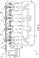
- FIG. 2 illustrates the schematic of the engine 100 under the outer cover 101.
- the engine 100 includes a cylinder head 102 and a cylinder block 104.
- the cylinder block 104 defines a plurality of bores 106 extending from a first end 108 of the cylinder block 104 to a second end 110 of the cylinder block 104.
- the cylinder head 102, the plurality of bores 106 in the cylinder block 104 and a plurality of pistons 112 define a plurality of combustion chambers 114.
- the plurality of combustion chambers 114 are configured to receive air and/or fuel mixture i.e. charge.
- the plurality of pistons 112 are configured to reciprocate within the plurality of bores 106 between a top dead center (the uppermost position in the bores 106 where the piston 112 reaches) and a bottom dead center (the lowermost position where the piston 112 reaches), during engine operation.
- the plurality of pistons 112 may be pivotably coupled to connecting rods 118.
- the plurality of pistons 112 slide or reciprocate within the plurality of bores 106.
- the reciprocating movement of the plurality of pistons 112 causes a crankshaft 116, assembled within a crankcase (not shown), to rotate.
- the plurality of pistons 112 include piston heads that may receive and/or may be exposed to combustion gases (i.e. the gases generated on burning of charge) generated within the combustion chamber 114.
- combustion gases i.e. the gases generated on burning of charge
- the combustion gases moves the plurality of pistons 112 and transmits the driving force created by the burning charge to the crankshaft 116.
- the cylinder head 102 may define one or more valve openings for receiving a valve.
- the valve openings may be in fluid communication with an intake port 120 and an exhaust port 122 of each combustion chamber of the plurality of combustion chamber 114, as shown in FIG. 1 .
- An intake valve 124 and an exhaust valve 126 may be disposed at least partially in the valve openings disposed in the cylinder head 102.
- the exhaust valve 126 may be configured to be opened by an exhaust cam (not shown) to facilitate discharge of the combustion products from the combustion chamber 114.
- the intake valve 124 may be configured to be opened by an intake cam (not shown) to supply charge/air into the combustion chamber 114.
- the charge may be introduced into the combustion chamber 114 by a fuel injection system 128 provided in the engine 100.
- the fuel injection system 128 includes a fuel tank 130, a fuel pipe assembly 132, a cover assembly 134, a plurality of fuel injection units 136 and a master pump 140.
- the fuel tank 130 includes an outlet 138.
- the outlet 138 is coupled to the master pump 140 via a fuel line 141.
- the master pump 140 is coupled to the plurality of fuel injection units 136 via the fuel pipe assembly 132.
- the master pump 140 is configured to supply pressurized fuel from the fuel tank 130 to the plurality of fuel injection units 136.
- the plurality of fuel injection units 136 are configured to directly inject one or more fuel charges into the plurality of combustion chambers 114.
- the plurality of fuel injection units 136 include a plurality of fuel injectors configured to inject a sequence of one or more fuel jets into the combustion chamber 114.
- the fuel injection system 128 is a direct injection system.
- the fuel injection system 128 may be a common rail coupled to at least a fuel pump configured to inject pressurized fuel the combustion chamber 114 via fuel intake valves.
- the fuel injection system 128 may be a fuel introducing system configured to introduce fuel into the plurality of combustion chambers 114 via conduits/ports/valves.
- the fuel injection system 128 may be any fuel injection system known in the art.
- the fuel injection system 128 will now be explained in detail with reference to FIG. 2 .
- the plurality of fuel injection units 136 include a first fuel injection unit 142, a second fuel injection unit 144, a third fuel injection unit 146 and a fourth fuel injection unit 148.
- Each of the first fuel injection unit 142, second fuel injection unit 144, third fuel injection unit 146 and fourth fuel injection unit 148 is configured to inject a sequence of one or more fuel jets into the combustion chambers 114.
- the first fuel injection unit 142, second fuel injection unit 144, third fuel injection unit 146 and fourth fuel injection unit 148 are fuel injectors.
- each of the first fuel injection unit 142, second fuel injection unit 144, third fuel injection unit 146 and fourth fuel injection unit 148 may include a fuel injection pump and a valve to inject fuel jets into the combustion chamber 114.
- the plurality of fuel injection units 136 may include a common fuel rail having a pressurized fuel and a fuel inlet valve configured to inject fuel into the combustion chamber 114.
- the fuel injection system 128 includes four fuel injection units (as FIG. 2 illustrates a four cylinder engine) it may be contemplated that the engine 100 may have varying number of cylinders and accordingly may have more/less than four fuel injection units.
- Each of the first fuel injection unit 142, second fuel injection unit 144, third fuel injection unit 146 and fourth fuel injection unit 148 includes a coupling assembly 150, as illustrated in FIG. 2 .
- the coupling assembly 150 has an inlet end 152 and an outlet end 154. Both the inlet end 152 and the outlet end 154 include a flange 156. Within the flange 156 openings 158 are provided. These openings 158 are configured to receive at least one pipe of the fuel pipe assembly 132.
- the fuel pipe assembly 132 includes a first pipe 160 and a second pipe 162.
- the first pipe 160 is coupled to the master pump 140 at one end is received within one of the openings 158 provided on the first fuel injection unit 142 and second fuel injection unit 144 (as illustrated in FIG. 3 ).
- third fuel injection unit 146 and fourth fuel injection unit 148 may be similar to the first fuel injection unit 142 and the second fuel injection unit 144. Accordingly, the first pipe 160 may also be received within openings provided on the third fuel injection unit 146 and fourth fuel injection unit 148.
- the second pipe 162 of the fuel pipe assembly 132 may be coupled to the fuel tank 130 at one of its end. Further, the second pipe 162 is received within one of the openings 158 provided on the first fuel injection unit 142 and second fuel injection unit 144 (as illustrated in FIG. 3 ). As discussed above, it may be contemplated that third fuel injection unit 146 and fourth fuel injection unit 148 may be similar to the first fuel injection unit 142 and the second fuel injection unit 144. Accordingly, the second pipe 162 may also be received within openings provided on the third fuel injection unit 146 and fourth fuel injection unit 148. Both the first pipe 160 and the second pipe 162 may be blocked by a plug 186 proximal to the fourth fuel injection unit 148.
- the first pipe 160 and the second pipe 162 are tubular pipes passing through the plurality of fuel injection units 136.
- the first pipe 160 and the second pipe 162 may be composed of a plurality of pipes (smaller sized pipes).
- the first pipe 160 may be composed of four small sized pipes.
- One pipe may be coupling the master pump 140 to the first fuel injection unit 142
- another pipe may be coupling the first fuel injection unit 142 to the second fuel injection unit 144
- yet another pipe may be coupling the second fuel injection unit 144 to the third fuel injection unit 146
- a final fourth pipe may be coupling the third fuel injection unit 146 to the fourth fuel injection unit 148.
- the second pipe 162 may also be made up of a plurality of pipes.
- the first pipe 160 is configured to supply pressurized fuel from the master pump 140 to the first fuel injection unit 142, second fuel injection unit 144, third fuel injection unit 146 and fourth fuel injection unit 148.
- Each of the first fuel injection unit 142, second fuel injection unit 144, third fuel injection unit 146, fourth fuel injection unit 148 includes a tip that is in fluid communication with the combustion chamber 114. Using this tip, the first fuel injection unit 142, second fuel injection unit 144, third fuel injection unit 146, fourth fuel injection unit 148 inject fuel/charge from the first pipe 160 into the plurality of combustion chambers 114.
- the first pipe 160 may supply excess fuel (more than required by the plurality of fuel injection units 136) to one or more of the first fuel injection unit 142, second fuel injection unit 144, third fuel injection unit 146 and fourth fuel injection unit 148.
- the additional/excess fuel is returned, by one or more of the first fuel injection unit 142, second fuel injection unit 144, third fuel injection unit 146 and fourth fuel injection unit 148, into the fuel tank 130 via the second pipe 162.
- the second pipe 162 is blocked by the plug 186 at one end and coupled to the fuel tank 130 at the other end.
- Such a configuration redirects the additional/excess fuel from the second pipe 162 to the fuel tank 130.
- Such a setup enables the additional/excess fuel to be recycled for latter use.
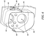
- the cover assembly 134 includes a first structure 164 and a second structure 166.
- the first structure 164 extends along a portion of a length of the fuel pipe assembly 132.
- the first structure 164 may be of length 'l 1 '. This first structure 164 of length 'l 1 ' is placed over a length of the first pipe 160 and/or the second pipe 162 present between the first fuel injection unit 142 and the second fuel injection unit 144 i.e.
- the first structure 164 is configured to partially encapsulate an upper portion of the fuel pipe assembly 132.
- the first structure 164 is a U shaped (bent shaped/curved) structure having a first edge 168 and a second edge 170.
- the U shaped first structure 164 may be made up of a sheet metal.
- the sheet metal may be any one of carbon steel, cast iron 302 and 304, stainless steel 316, stainless steel, bronze, 416 stainless steel, etc.
- the U shaped first structure 164 may also be made up of plastic materials.
- the first structure 164 may be made of plastic that is resistant to corrosion from the fuel being used in the engine 100.
- the first edge 168 and the second edge 170 of the first structure 164 extend along a length of the first structure 164 i.e. the length 'l 1 '.
- a plurality of rotary latches 172 are provided proximal to/on the first edge 168 and the second edge 170 of the first structure 164.
- the plurality of rotary latches 172 may be uniformly spaced apart from each other along a length of the first edge 168 and the second edge 170.
- Each of the latch of the plurality of latches 172 includes a clamping plate 180 that is a movable (pivotable) plate, as illustrated in FIG. 5 .
- the clamping plate 180 has a hook structure 182 configured to engage with the second structure 166 and couple the first structure 164 with the second structure 166.
- the second structure 166 of the cover assembly 134 also extends along the portion of the length of the fuel pipe assembly 132 i.e. the second structure 166 also extends for the length 'l 1 '.
- the second structure 166 is also a U shaped structure having a third edge 174 and a fourth edge 176.
- the third edge 174 and the fourth edge 176 extend along a length of the second structure (i.e. extends for the length 'l 1 ').
- the third edge 174 and the fourth edge 176 are bent to form an arcuate/bent profile 178 having a radius 'r'.
- the second structure 166 may also be made up of a sheet metal wherein the sheet metal may be any one of carbon steel, cast iron 302 and 304, stainless steel 316, stainless steel, bronze, 416 stainless steel, etc.
- the U shaped second structure 166 may also be made up of plastic materials.
- the second structure 166 may be made of plastic that is resistant to corrosion from the fuel being used in the engine 100.
- the second structure 166 of length 'l 1 ' is also placed on the fuel pipe assembly 132 i.e. over the length of the first pipe 160 and/or the second pipe 162 present between the first fuel injection unit 142 and the second fuel injection unit 144.
- the second structure 166 is also configured to partially encapsulate the fuel pipe assembly 132.
- the second structure 166 is configured to partially encapsulate a lower portion of the fuel pipe assembly 132.
- the first structure 164 is placed over the upper portion of the fuel pipe assembly 132 and the second structure 166 is placed such that it partially encapsulates the lower portion of the fuel pipe assembly 132.
- the first structure 164 and the second structure 166 are placed such that the first edge 168 of the first structure 164 aligns with the third edge 174 of the second structure 166 and the second edge 170 of the first structure 164 aligns with the fourth edge 176 of the second structure 166.
- the first structure 164 is then coupled to the second structure 166 by engaging the hook structure 182 of the plurality of rotary latches 172 provided on the first structure 164 with the arcuate profile 178 of the second structure 166.
- Such coupling of the first structure 164 and the second structure 166 fully encapsulates the first pipe 160 and the second pipe 162 present between the first fuel injection unit 142 and the second fuel injection unit 144 (i.e. encapsulates the portion of the length 'l 1 ' of the fuel pipe assembly 132).
- the combination of the first structure 164 and the second structure 166 take the shape similar to that of the flange 156 of the plurality of fuel injection units 136. Further, since the length 'l 1 ' of the coupled assembly of the first structure 164 to the second structure 166 is greater than the length 'l 2 ' (length of the first pipe 160 and/or the second pipe 162 present between the first fuel injection unit 142 and the second fuel injection unit 144), the excess length of the coupled assembly of the first structure 164 and the second structure 166 i.e. difference of length 'l 1 ' and 'l 2 ' of the first structure 164 and the second structure 166 force fits on to the flange 156 of the one or more of the plurality of fuel injection units 136.
- the first fuel injection unit 142 has the flange 156 (on the outlet end 154) and the second fuel injection unit 144 also has the flange 156 (on the inlet end 152).
- the first structure 164 and the second structure 166 are coupled to each other the coupled assembly of the first structure 164 and the second structure 166 form a shape similar to the flange 156 at both ends of the cover assembly 134.
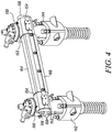
- the length 'l 1 ' of the coupled assembly of the first structure 164 to the second structure 166 is greater than the length 'l 2 ' the excess length of the coupled assembly of the first structure 164 and the second structure 166 fits over the flange 156 of the first fuel injection unit 142 and the flange 156 of the second fuel injection unit 144, as illustrated in FIG. 3 and FIG. 4 .
- flanges provided on the each of the first fuel injection unit 142, second fuel injection unit 144, third fuel injection unit 146 and fourth fuel injection unit 148 are identical to each other.
- the each of the fuel injector of the plurality of fuel injection units 136 may have a unique flange shape.
- the first structure 164 and the second structure 166 may take shapes corresponding to the flanges of the fuel injector units, when coupled to each other.
- Internal combustion engines include cylinder(s) (having a combustion chamber) configured to receive fuel/air-fuel mixture i.e. charge.
- the charge is delivered to the cylinder(s) by a fuel rail that may include single or multiple pipes from which fuel is supplied to multiple injectors and subsequently to the cylinder of the internal combustion engine.
- the cover assembly 134 is provided for the fuel pipe assembly 132 of the engine 100, as illustrated in FIG. 2 and FIG. 4 .
- the cover assembly 134 includes the first structure 164 configured to be placed on the fuel pipe assembly 132 and extending along a portion of the length ('l 1 ') of the fuel pipe assembly 132, the first structure 164 configured to partially encapsulate the portion of length ('l 1 ') of the fuel pipe assembly 132.
- the cover assembly 134 further includes the second structure 166 configured to extend along the portion of the length of the fuel pipe assembly 132 and configured to be coupled to the first structure 164 such that the first structure 164 and the second structure 166 encapsulate the portion of the length of the fuel pipe assembly 132.
- coupling the plurality of rotary latches 172 with the arcuate profile 178 force-fits the cover assembly 134 on to the flange 156 (proximal to outlet end 154) of the first fuel injection unit 142 and the flange 156 (proximal to inlet end 152) of the second fuel injection unit 144.
- Such a configuration i.e. the coupled combination of the first structure 164 and the second structure 166 and the coupling assembly 150 of the first fuel injection unit 142 and the second fuel injection unit 144 encapsulates the first pipe 160 and the second pipe 162 present between the first fuel injection unit 142 and the second fuel injection unit 144.
- any leakage in the first pipe 160 and/or the second pipe 162 can be contained within the cover assembly 134. This prevents leakage of oil/fuel from the first pipe 160 and/or the second pipe 162 and prevents spillage of oil/fuel on any component of the engine 100. Further, in case fuel/oil gets accumulated within the cover assembly 134.
- the clamping plate 180 may be moved to decouple the first structure 164 and the second structure 166. The fuel accumulated in the second structure 166 and/or the first structure 164 can be removed/drained. The first structure 164 and second structure 166 may then be cleaned and may again be coupled to each other to encapsulate the first pipe 160 and the second pipe 162.
- the same components may be used for a long period of time to prevent oil/fuel from spilling from the fuel pipe assembly 132 onto the high temperature components of the engine 100.
- the cover assembly 134 of the present disclosure may also be suitable for being mounted to the fuel pipe assembly 132 without disassembling the fuel pipe assembly 132.
Landscapes
- Engineering & Computer Science (AREA)
- Chemical & Material Sciences (AREA)
- Combustion & Propulsion (AREA)
- Mechanical Engineering (AREA)
- General Engineering & Computer Science (AREA)
- Fuel-Injection Apparatus (AREA)
Claims (7)
- Kraftmaschine (100) mit einem Kraftstoffeinspritzsystem (128), das dafür ausgelegt ist, Kraftstoff in eine Vielzahl von Brennkammern (114) einzuspritzen, wobei das Kraftstoffeinspritzsystem (128) eine erste Kraftstoffeinspritzeinheit (142) und eine zweite Kraftstoffeinspritzeinheit (144) umfasst und die Kraftmaschine (100) Folgendes umfasst:eine Kraftstoffrohranordnung (132) mit mindestens einer Kraftstoffrohrleitung (160), die mit der ersten Kraftstoffeinspritzeinheit (142) und der zweiten Kraftstoffeinspritzeinheit (144) fluidtechnisch gekoppelt ist; undeine Abdeckbaugruppe (134), umfassend:eine U-förmige erste Struktur (164), die eine erste Kante (168) und eine zweiten Kante (170) aufweist, welche sich entlang einer Länge der ersten Struktur (164) erstrecken, und die dafür ausgelegt ist, auf der Kraftstoffrohranordnung (132) platziert zu werden und sich entlang eines Abschnitts der Länge der Kraftstoffrohranordnung (132) zu erstrecken, wobei die erste Struktur (164) dafür ausgelegt ist, den Abschnitt der Länge der Kraftstoffrohranordnung (132) teilweise einzukapseln; undeine zweite Struktur (166), die sich entlang des Abschnitts der Länge der Kraftstoffrohranordnung (132) erstreckt und dafür ausgelegt ist, mit der ersten Struktur (164) gekoppelt zu werden, derart, dass die erste Struktur (164) und die zweite Struktur (166) den Abschnitt der Länge der Kraftstoffrohranordnung (132) einkapseln,dadurch gekennzeichnet, dass die erste Struktur (164) eine Vielzahl von Drehriegeln (172) einschließt, die an der ersten Kante (168) und der zweiten Kante (170) bereitgestellt sind.
- Kraftmaschine nach Anspruch 1, wobei die zweite Struktur (166) eine U-förmige Struktur ist, die eine dritte Kante (174) und eine vierte Kante (176) aufweist, die sich entlang einer Länge der zweiten Struktur (166) erstrecken.
- Kraftmaschine nach Anspruch 2, wobei die dritte Kante (174) und die vierte Kante (176) gebogen sind, um ein bogenförmiges Profil (178) zu bilden.
- Kraftmaschine nach Anspruch 3, wobei die zweite Struktur (166) mit der ersten Struktur (164) koppelt, wenn die Vielzahl von Drehriegeln (172) der ersten Struktur (164) innerhalb des bogenförmigen Profils (178) der zweiten Struktur (166) aufgenommen wird.
- Kraftmaschine nach Anspruch 1, wobei die erste Struktur (164) und die zweite Struktur (166) aus Blech hergestellt sind.
- Kraftmaschine nach Anspruch 4, wobei die erste Kraftstoffeinspritzeinheit (142) einen ersten Flansch (156) einschließt und die zweite Kraftstoffeinspritzeinheit (144) einen zweiten Flansch (156) einschließt.
- Kraftmaschine nach Anspruch 6, wobei das Koppeln der Vielzahl von Drehriegeln (172) mit dem bogenförmigen Profil (178) einen Presssitz der Abdeckbaugruppe (134) auf dem ersten Flansch (156) und dem zweiten Flansch (156) der ersten Kraftstoffeinspritzeinheit (142) bzw. der zweiten Kraftstoffeinspritzeinheit (144) bewirkt.
Priority Applications (1)
| Application Number | Priority Date | Filing Date | Title |
|---|---|---|---|
| EP17167736.2A EP3396142B1 (de) | 2017-04-24 | 2017-04-24 | Abdeckung für kraftstoffrohranordnung |
Applications Claiming Priority (1)
| Application Number | Priority Date | Filing Date | Title |
|---|---|---|---|
| EP17167736.2A EP3396142B1 (de) | 2017-04-24 | 2017-04-24 | Abdeckung für kraftstoffrohranordnung |
Publications (2)
| Publication Number | Publication Date |
|---|---|
| EP3396142A1 EP3396142A1 (de) | 2018-10-31 |
| EP3396142B1 true EP3396142B1 (de) | 2020-12-02 |
Family
ID=58672341
Family Applications (1)
| Application Number | Title | Priority Date | Filing Date |
|---|---|---|---|
| EP17167736.2A Active EP3396142B1 (de) | 2017-04-24 | 2017-04-24 | Abdeckung für kraftstoffrohranordnung |
Country Status (1)
| Country | Link |
|---|---|
| EP (1) | EP3396142B1 (de) |
Family Cites Families (6)
| Publication number | Priority date | Publication date | Assignee | Title |
|---|---|---|---|---|
| GB1263198A (en) * | 1970-11-11 | 1972-02-09 | Associated Insulation Of Calif | An insulation unit for pipes |
| FR2538076B1 (fr) * | 1982-12-20 | 1987-04-30 | Thibonnet Bernard | Dispositif d'alimentation en combustibles liquides |
| GB9512285D0 (en) * | 1995-06-16 | 1995-08-16 | Rover Group | A pipe assembly |
| FR2943115B1 (fr) * | 2009-03-10 | 2011-04-29 | Poujoulat | Equipement pour combler le pourtour d'un orifice menage dans une paroi pour permettre le passage d'un conduit |
| ITBA20090019A1 (it) * | 2009-05-15 | 2010-11-15 | Refrasud Internat S R L | Rivestimento refrattario di tubazioni raffreddate |
| US20150129076A1 (en) * | 2015-01-23 | 2015-05-14 | Caterpillar Inc. | Fuel supply routing assembly for engine to detect fuel leakage |
-
2017
- 2017-04-24 EP EP17167736.2A patent/EP3396142B1/de active Active
Non-Patent Citations (1)
| Title |
|---|
| None * |
Also Published As
| Publication number | Publication date |
|---|---|
| EP3396142A1 (de) | 2018-10-31 |
Similar Documents
| Publication | Publication Date | Title |
|---|---|---|
| US6427667B1 (en) | Fuel injector mounting arrangement | |
| US7299787B2 (en) | Internal combustion engine intake device | |
| RU2696185C2 (ru) | Хомут топливной форсунки дизельного двигателя (варианты) и узел двигателя, содержащий хомут топливной форсунки | |
| US20160017839A1 (en) | Piston Engine with Non-Circular Combustion Chamber | |
| US6612272B2 (en) | Cooling arrangement for direct injected engine | |
| US6213096B1 (en) | Fuel supply for direct injected engine | |
| JP6657138B2 (ja) | 2ストローククロスヘッドタイプの内燃機関、並びに燃料及び水を燃焼室へ直接噴射する方法 | |
| US9808745B2 (en) | Filter element and filter assembly with recirculation | |
| US6295969B1 (en) | Injector mounting arrangement for direct-injected engines | |
| KR102110588B1 (ko) | 2 행정 크로스헤드 기관용 실린더 라이너 | |
| US4020801A (en) | Two-stroke, multicylinder, spark ignition, pumpless injection internal combustion engine | |
| EP1015757B1 (de) | Viertaktdieselmotor mit katalytischem konverter | |
| US20030029396A1 (en) | Oil injection system | |
| DE202010013762U1 (de) | Verbrennungsmotor | |
| JP2003514171A (ja) | 内燃機関のためのインジェクター内の一定な逃がしオイル圧力を有する燃料噴射システム | |
| EP3396142A1 (de) | Abdeckung für kraftstoffrohranordnung | |
| US9670853B2 (en) | Outboard motor | |
| US6112707A (en) | Engine fuel system with a super charged air compressor | |
| CN104508271A (zh) | 模块化冷却剂芯件-气缸盖 | |
| US10036358B2 (en) | Fuel supply device of engine | |
| US6357402B1 (en) | Direct injected engine for outboard motor | |
| CN115013206A (zh) | 一种用于点燃压燃发动机的油轨总成及发动机 | |
| KR102681937B1 (ko) | 선박용 디젤 엔진 | |
| US20200173357A1 (en) | Internal combustion engine with two working spaces of a cylinder | |
| US9624881B2 (en) | Airbox for engine |
Legal Events
| Date | Code | Title | Description |
|---|---|---|---|
| PUAI | Public reference made under article 153(3) epc to a published international application that has entered the european phase |
Free format text: ORIGINAL CODE: 0009012 |
|
| STAA | Information on the status of an ep patent application or granted ep patent |
Free format text: STATUS: THE APPLICATION HAS BEEN PUBLISHED |
|
| AK | Designated contracting states |
Kind code of ref document: A1 Designated state(s): AL AT BE BG CH CY CZ DE DK EE ES FI FR GB GR HR HU IE IS IT LI LT LU LV MC MK MT NL NO PL PT RO RS SE SI SK SM TR |
|
| AX | Request for extension of the european patent |
Extension state: BA ME |
|
| STAA | Information on the status of an ep patent application or granted ep patent |
Free format text: STATUS: REQUEST FOR EXAMINATION WAS MADE |
|
| 17P | Request for examination filed |
Effective date: 20190426 |
|
| RBV | Designated contracting states (corrected) |
Designated state(s): AL AT BE BG CH CY CZ DE DK EE ES FI FR GB GR HR HU IE IS IT LI LT LU LV MC MK MT NL NO PL PT RO RS SE SI SK SM TR |
|
| REG | Reference to a national code |
Ref country code: DE Ref legal event code: R079 Ref document number: 602017028621 Country of ref document: DE Free format text: PREVIOUS MAIN CLASS: F02F0007000000 Ipc: F02B0037000000 |
|
| RIC1 | Information provided on ipc code assigned before grant |
Ipc: F02M 55/00 20060101ALI20200429BHEP Ipc: F02M 55/02 20060101ALI20200429BHEP Ipc: F02B 67/10 20060101ALI20200429BHEP Ipc: F02F 7/00 20060101ALI20200429BHEP Ipc: F02B 37/02 20060101ALI20200429BHEP Ipc: F02B 37/00 20060101AFI20200429BHEP |
|
| GRAP | Despatch of communication of intention to grant a patent |
Free format text: ORIGINAL CODE: EPIDOSNIGR1 |
|
| STAA | Information on the status of an ep patent application or granted ep patent |
Free format text: STATUS: GRANT OF PATENT IS INTENDED |
|
| INTG | Intention to grant announced |
Effective date: 20200630 |
|
| GRAS | Grant fee paid |
Free format text: ORIGINAL CODE: EPIDOSNIGR3 |
|
| GRAA | (expected) grant |
Free format text: ORIGINAL CODE: 0009210 |
|
| STAA | Information on the status of an ep patent application or granted ep patent |
Free format text: STATUS: THE PATENT HAS BEEN GRANTED |
|
| AK | Designated contracting states |
Kind code of ref document: B1 Designated state(s): AL AT BE BG CH CY CZ DE DK EE ES FI FR GB GR HR HU IE IS IT LI LT LU LV MC MK MT NL NO PL PT RO RS SE SI SK SM TR |
|
| REG | Reference to a national code |
Ref country code: GB Ref legal event code: FG4D |
|
| REG | Reference to a national code |
Ref country code: AT Ref legal event code: REF Ref document number: 1341171 Country of ref document: AT Kind code of ref document: T Effective date: 20201215 Ref country code: CH Ref legal event code: EP |
|
| REG | Reference to a national code |
Ref country code: IE Ref legal event code: FG4D |
|
| REG | Reference to a national code |
Ref country code: DE Ref legal event code: R096 Ref document number: 602017028621 Country of ref document: DE |
|
| REG | Reference to a national code |
Ref country code: FI Ref legal event code: FGE |
|
| PG25 | Lapsed in a contracting state [announced via postgrant information from national office to epo] |
Ref country code: RS Free format text: LAPSE BECAUSE OF FAILURE TO SUBMIT A TRANSLATION OF THE DESCRIPTION OR TO PAY THE FEE WITHIN THE PRESCRIBED TIME-LIMIT Effective date: 20201202 Ref country code: NO Free format text: LAPSE BECAUSE OF FAILURE TO SUBMIT A TRANSLATION OF THE DESCRIPTION OR TO PAY THE FEE WITHIN THE PRESCRIBED TIME-LIMIT Effective date: 20210302 Ref country code: GR Free format text: LAPSE BECAUSE OF FAILURE TO SUBMIT A TRANSLATION OF THE DESCRIPTION OR TO PAY THE FEE WITHIN THE PRESCRIBED TIME-LIMIT Effective date: 20210303 |
|
| REG | Reference to a national code |
Ref country code: NL Ref legal event code: MP Effective date: 20201202 |
|
| REG | Reference to a national code |
Ref country code: AT Ref legal event code: MK05 Ref document number: 1341171 Country of ref document: AT Kind code of ref document: T Effective date: 20201202 |
|
| PG25 | Lapsed in a contracting state [announced via postgrant information from national office to epo] |
Ref country code: SE Free format text: LAPSE BECAUSE OF FAILURE TO SUBMIT A TRANSLATION OF THE DESCRIPTION OR TO PAY THE FEE WITHIN THE PRESCRIBED TIME-LIMIT Effective date: 20201202 Ref country code: BG Free format text: LAPSE BECAUSE OF FAILURE TO SUBMIT A TRANSLATION OF THE DESCRIPTION OR TO PAY THE FEE WITHIN THE PRESCRIBED TIME-LIMIT Effective date: 20210302 Ref country code: PL Free format text: LAPSE BECAUSE OF FAILURE TO SUBMIT A TRANSLATION OF THE DESCRIPTION OR TO PAY THE FEE WITHIN THE PRESCRIBED TIME-LIMIT Effective date: 20201202 Ref country code: LV Free format text: LAPSE BECAUSE OF FAILURE TO SUBMIT A TRANSLATION OF THE DESCRIPTION OR TO PAY THE FEE WITHIN THE PRESCRIBED TIME-LIMIT Effective date: 20201202 |
|
| PG25 | Lapsed in a contracting state [announced via postgrant information from national office to epo] |
Ref country code: NL Free format text: LAPSE BECAUSE OF FAILURE TO SUBMIT A TRANSLATION OF THE DESCRIPTION OR TO PAY THE FEE WITHIN THE PRESCRIBED TIME-LIMIT Effective date: 20201202 Ref country code: HR Free format text: LAPSE BECAUSE OF FAILURE TO SUBMIT A TRANSLATION OF THE DESCRIPTION OR TO PAY THE FEE WITHIN THE PRESCRIBED TIME-LIMIT Effective date: 20201202 |
|
| REG | Reference to a national code |
Ref country code: LT Ref legal event code: MG9D |
|
| PG25 | Lapsed in a contracting state [announced via postgrant information from national office to epo] |
Ref country code: CZ Free format text: LAPSE BECAUSE OF FAILURE TO SUBMIT A TRANSLATION OF THE DESCRIPTION OR TO PAY THE FEE WITHIN THE PRESCRIBED TIME-LIMIT Effective date: 20201202 Ref country code: EE Free format text: LAPSE BECAUSE OF FAILURE TO SUBMIT A TRANSLATION OF THE DESCRIPTION OR TO PAY THE FEE WITHIN THE PRESCRIBED TIME-LIMIT Effective date: 20201202 Ref country code: SM Free format text: LAPSE BECAUSE OF FAILURE TO SUBMIT A TRANSLATION OF THE DESCRIPTION OR TO PAY THE FEE WITHIN THE PRESCRIBED TIME-LIMIT Effective date: 20201202 Ref country code: LT Free format text: LAPSE BECAUSE OF FAILURE TO SUBMIT A TRANSLATION OF THE DESCRIPTION OR TO PAY THE FEE WITHIN THE PRESCRIBED TIME-LIMIT Effective date: 20201202 Ref country code: PT Free format text: LAPSE BECAUSE OF FAILURE TO SUBMIT A TRANSLATION OF THE DESCRIPTION OR TO PAY THE FEE WITHIN THE PRESCRIBED TIME-LIMIT Effective date: 20210405 Ref country code: RO Free format text: LAPSE BECAUSE OF FAILURE TO SUBMIT A TRANSLATION OF THE DESCRIPTION OR TO PAY THE FEE WITHIN THE PRESCRIBED TIME-LIMIT Effective date: 20201202 Ref country code: SK Free format text: LAPSE BECAUSE OF FAILURE TO SUBMIT A TRANSLATION OF THE DESCRIPTION OR TO PAY THE FEE WITHIN THE PRESCRIBED TIME-LIMIT Effective date: 20201202 |
|
| PG25 | Lapsed in a contracting state [announced via postgrant information from national office to epo] |
Ref country code: AT Free format text: LAPSE BECAUSE OF FAILURE TO SUBMIT A TRANSLATION OF THE DESCRIPTION OR TO PAY THE FEE WITHIN THE PRESCRIBED TIME-LIMIT Effective date: 20201202 |
|
| REG | Reference to a national code |
Ref country code: DE Ref legal event code: R097 Ref document number: 602017028621 Country of ref document: DE |
|
| PG25 | Lapsed in a contracting state [announced via postgrant information from national office to epo] |
Ref country code: IS Free format text: LAPSE BECAUSE OF FAILURE TO SUBMIT A TRANSLATION OF THE DESCRIPTION OR TO PAY THE FEE WITHIN THE PRESCRIBED TIME-LIMIT Effective date: 20210402 |
|
| PLBE | No opposition filed within time limit |
Free format text: ORIGINAL CODE: 0009261 |
|
| STAA | Information on the status of an ep patent application or granted ep patent |
Free format text: STATUS: NO OPPOSITION FILED WITHIN TIME LIMIT |
|
| PG25 | Lapsed in a contracting state [announced via postgrant information from national office to epo] |
Ref country code: AL Free format text: LAPSE BECAUSE OF FAILURE TO SUBMIT A TRANSLATION OF THE DESCRIPTION OR TO PAY THE FEE WITHIN THE PRESCRIBED TIME-LIMIT Effective date: 20201202 |
|
| 26N | No opposition filed |
Effective date: 20210903 |
|
| PG25 | Lapsed in a contracting state [announced via postgrant information from national office to epo] |
Ref country code: DK Free format text: LAPSE BECAUSE OF FAILURE TO SUBMIT A TRANSLATION OF THE DESCRIPTION OR TO PAY THE FEE WITHIN THE PRESCRIBED TIME-LIMIT Effective date: 20201202 Ref country code: MC Free format text: LAPSE BECAUSE OF FAILURE TO SUBMIT A TRANSLATION OF THE DESCRIPTION OR TO PAY THE FEE WITHIN THE PRESCRIBED TIME-LIMIT Effective date: 20201202 Ref country code: SI Free format text: LAPSE BECAUSE OF FAILURE TO SUBMIT A TRANSLATION OF THE DESCRIPTION OR TO PAY THE FEE WITHIN THE PRESCRIBED TIME-LIMIT Effective date: 20201202 |
|
| GBPC | Gb: european patent ceased through non-payment of renewal fee |
Effective date: 20210424 |
|
| PG25 | Lapsed in a contracting state [announced via postgrant information from national office to epo] |
Ref country code: LU Free format text: LAPSE BECAUSE OF NON-PAYMENT OF DUE FEES Effective date: 20210424 |
|
| REG | Reference to a national code |
Ref country code: BE Ref legal event code: MM Effective date: 20210430 |
|
| PG25 | Lapsed in a contracting state [announced via postgrant information from national office to epo] |
Ref country code: LI Free format text: LAPSE BECAUSE OF NON-PAYMENT OF DUE FEES Effective date: 20210430 Ref country code: CH Free format text: LAPSE BECAUSE OF NON-PAYMENT OF DUE FEES Effective date: 20210430 Ref country code: GB Free format text: LAPSE BECAUSE OF NON-PAYMENT OF DUE FEES Effective date: 20210424 Ref country code: ES Free format text: LAPSE BECAUSE OF FAILURE TO SUBMIT A TRANSLATION OF THE DESCRIPTION OR TO PAY THE FEE WITHIN THE PRESCRIBED TIME-LIMIT Effective date: 20201202 |
|
| PG25 | Lapsed in a contracting state [announced via postgrant information from national office to epo] |
Ref country code: IE Free format text: LAPSE BECAUSE OF NON-PAYMENT OF DUE FEES Effective date: 20210424 |
|
| PG25 | Lapsed in a contracting state [announced via postgrant information from national office to epo] |
Ref country code: IS Free format text: LAPSE BECAUSE OF FAILURE TO SUBMIT A TRANSLATION OF THE DESCRIPTION OR TO PAY THE FEE WITHIN THE PRESCRIBED TIME-LIMIT Effective date: 20210402 |
|
| PG25 | Lapsed in a contracting state [announced via postgrant information from national office to epo] |
Ref country code: BE Free format text: LAPSE BECAUSE OF NON-PAYMENT OF DUE FEES Effective date: 20210430 |
|
| P01 | Opt-out of the competence of the unified patent court (upc) registered |
Effective date: 20230517 |
|
| PG25 | Lapsed in a contracting state [announced via postgrant information from national office to epo] |
Ref country code: CY Free format text: LAPSE BECAUSE OF FAILURE TO SUBMIT A TRANSLATION OF THE DESCRIPTION OR TO PAY THE FEE WITHIN THE PRESCRIBED TIME-LIMIT Effective date: 20201202 |
|
| PG25 | Lapsed in a contracting state [announced via postgrant information from national office to epo] |
Ref country code: HU Free format text: LAPSE BECAUSE OF FAILURE TO SUBMIT A TRANSLATION OF THE DESCRIPTION OR TO PAY THE FEE WITHIN THE PRESCRIBED TIME-LIMIT; INVALID AB INITIO Effective date: 20170424 |
|
| PG25 | Lapsed in a contracting state [announced via postgrant information from national office to epo] |
Ref country code: MK Free format text: LAPSE BECAUSE OF FAILURE TO SUBMIT A TRANSLATION OF THE DESCRIPTION OR TO PAY THE FEE WITHIN THE PRESCRIBED TIME-LIMIT Effective date: 20201202 |
|
| PG25 | Lapsed in a contracting state [announced via postgrant information from national office to epo] |
Ref country code: MT Free format text: LAPSE BECAUSE OF FAILURE TO SUBMIT A TRANSLATION OF THE DESCRIPTION OR TO PAY THE FEE WITHIN THE PRESCRIBED TIME-LIMIT Effective date: 20201202 |
|
| PGFP | Annual fee paid to national office [announced via postgrant information from national office to epo] |
Ref country code: DE Payment date: 20250319 Year of fee payment: 9 |
|
| PG25 | Lapsed in a contracting state [announced via postgrant information from national office to epo] |
Ref country code: TR Free format text: LAPSE BECAUSE OF FAILURE TO SUBMIT A TRANSLATION OF THE DESCRIPTION OR TO PAY THE FEE WITHIN THE PRESCRIBED TIME-LIMIT Effective date: 20201202 |
|
| PGFP | Annual fee paid to national office [announced via postgrant information from national office to epo] |
Ref country code: FI Payment date: 20260319 Year of fee payment: 10 Ref country code: IT Payment date: 20260319 Year of fee payment: 10 |
|
| PGFP | Annual fee paid to national office [announced via postgrant information from national office to epo] |
Ref country code: FR Payment date: 20260319 Year of fee payment: 10 |