EP3396178A1 - Organe de fixation et mécanisme de fixation - Google Patents
Organe de fixation et mécanisme de fixation Download PDFInfo
- Publication number
- EP3396178A1 EP3396178A1 EP16878937.8A EP16878937A EP3396178A1 EP 3396178 A1 EP3396178 A1 EP 3396178A1 EP 16878937 A EP16878937 A EP 16878937A EP 3396178 A1 EP3396178 A1 EP 3396178A1
- Authority
- EP
- European Patent Office
- Prior art keywords
- spring piece
- insert
- spring
- clip
- contact surface
- Prior art date
- Legal status (The legal status is an assumption and is not a legal conclusion. Google has not performed a legal analysis and makes no representation as to the accuracy of the status listed.)
- Granted
Links
Images


Classifications
-
- F—MECHANICAL ENGINEERING; LIGHTING; HEATING; WEAPONS; BLASTING
- F16—ENGINEERING ELEMENTS AND UNITS; GENERAL MEASURES FOR PRODUCING AND MAINTAINING EFFECTIVE FUNCTIONING OF MACHINES OR INSTALLATIONS; THERMAL INSULATION IN GENERAL
- F16B—DEVICES FOR FASTENING OR SECURING CONSTRUCTIONAL ELEMENTS OR MACHINE PARTS TOGETHER, e.g. NAILS, BOLTS, CIRCLIPS, CLAMPS, CLIPS OR WEDGES; JOINTS OR JOINTING
- F16B5/00—Joining sheets or plates, e.g. panels, to one another or to strips or bars parallel to them
- F16B5/06—Joining sheets or plates, e.g. panels, to one another or to strips or bars parallel to them by means of clamps or clips
-
- H—ELECTRICITY
- H05—ELECTRIC TECHNIQUES NOT OTHERWISE PROVIDED FOR
- H05K—PRINTED CIRCUITS; CASINGS OR CONSTRUCTIONAL DETAILS OF ELECTRIC APPARATUS; MANUFACTURE OF ASSEMBLAGES OF ELECTRICAL COMPONENTS
- H05K7/00—Constructional details common to different types of electric apparatus
- H05K7/02—Arrangements of circuit components or wiring on supporting structure
- H05K7/12—Resilient or clamping means for holding component to structure
-
- F—MECHANICAL ENGINEERING; LIGHTING; HEATING; WEAPONS; BLASTING
- F16—ENGINEERING ELEMENTS AND UNITS; GENERAL MEASURES FOR PRODUCING AND MAINTAINING EFFECTIVE FUNCTIONING OF MACHINES OR INSTALLATIONS; THERMAL INSULATION IN GENERAL
- F16B—DEVICES FOR FASTENING OR SECURING CONSTRUCTIONAL ELEMENTS OR MACHINE PARTS TOGETHER, e.g. NAILS, BOLTS, CIRCLIPS, CLAMPS, CLIPS OR WEDGES; JOINTS OR JOINTING
- F16B1/00—Devices for securing together, or preventing relative movement between, constructional elements or machine parts
-
- F—MECHANICAL ENGINEERING; LIGHTING; HEATING; WEAPONS; BLASTING
- F16—ENGINEERING ELEMENTS AND UNITS; GENERAL MEASURES FOR PRODUCING AND MAINTAINING EFFECTIVE FUNCTIONING OF MACHINES OR INSTALLATIONS; THERMAL INSULATION IN GENERAL
- F16B—DEVICES FOR FASTENING OR SECURING CONSTRUCTIONAL ELEMENTS OR MACHINE PARTS TOGETHER, e.g. NAILS, BOLTS, CIRCLIPS, CLAMPS, CLIPS OR WEDGES; JOINTS OR JOINTING
- F16B2/00—Friction-grip releasable fastenings
- F16B2/20—Clips, i.e. with gripping action effected solely by the inherent resistance to deformation of the material of the fastening
- F16B2/22—Clips, i.e. with gripping action effected solely by the inherent resistance to deformation of the material of the fastening of resilient material, e.g. rubbery material
- F16B2/24—Clips, i.e. with gripping action effected solely by the inherent resistance to deformation of the material of the fastening of resilient material, e.g. rubbery material of metal
- F16B2/241—Clips, i.e. with gripping action effected solely by the inherent resistance to deformation of the material of the fastening of resilient material, e.g. rubbery material of metal of sheet metal
- F16B2/245—Clips, i.e. with gripping action effected solely by the inherent resistance to deformation of the material of the fastening of resilient material, e.g. rubbery material of metal of sheet metal external, i.e. with contracting action
-
- H—ELECTRICITY
- H01—ELECTRIC ELEMENTS
- H01R—ELECTRICALLY-CONDUCTIVE CONNECTIONS; STRUCTURAL ASSOCIATIONS OF A PLURALITY OF MUTUALLY-INSULATED ELECTRICAL CONNECTING ELEMENTS; COUPLING DEVICES; CURRENT COLLECTORS
- H01R12/00—Structural associations of a plurality of mutually-insulated electrical connecting elements, specially adapted for printed circuits, e.g. printed circuit boards [PCB], flat or ribbon cables, or like generally planar structures, e.g. terminal strips, terminal blocks; Coupling devices specially adapted for printed circuits, flat or ribbon cables, or like generally planar structures; Terminals specially adapted for contact with, or insertion into, printed circuits, flat or ribbon cables, or like generally planar structures
- H01R12/50—Fixed connections
- H01R12/51—Fixed connections for rigid printed circuits or like structures
- H01R12/55—Fixed connections for rigid printed circuits or like structures characterised by the terminals
- H01R12/57—Fixed connections for rigid printed circuits or like structures characterised by the terminals surface mounting terminals
-
- H—ELECTRICITY
- H01—ELECTRIC ELEMENTS
- H01R—ELECTRICALLY-CONDUCTIVE CONNECTIONS; STRUCTURAL ASSOCIATIONS OF A PLURALITY OF MUTUALLY-INSULATED ELECTRICAL CONNECTING ELEMENTS; COUPLING DEVICES; CURRENT COLLECTORS
- H01R4/00—Electrically-conductive connections between two or more conductive members in direct contact, i.e. touching one another; Means for effecting or maintaining such contact; Electrically-conductive connections having two or more spaced connecting locations for conductors and using contact members penetrating insulation
- H01R4/28—Clamped connections, spring connections
- H01R4/48—Clamped connections, spring connections utilising a spring, clip, or other resilient member
-
- H—ELECTRICITY
- H05—ELECTRIC TECHNIQUES NOT OTHERWISE PROVIDED FOR
- H05K—PRINTED CIRCUITS; CASINGS OR CONSTRUCTIONAL DETAILS OF ELECTRIC APPARATUS; MANUFACTURE OF ASSEMBLAGES OF ELECTRICAL COMPONENTS
- H05K1/00—Printed circuits
- H05K1/18—Printed circuits structurally associated with non-printed electric components
-
- H—ELECTRICITY
- H05—ELECTRIC TECHNIQUES NOT OTHERWISE PROVIDED FOR
- H05K—PRINTED CIRCUITS; CASINGS OR CONSTRUCTIONAL DETAILS OF ELECTRIC APPARATUS; MANUFACTURE OF ASSEMBLAGES OF ELECTRICAL COMPONENTS
- H05K9/00—Screening of apparatus or components against electric or magnetic fields
- H05K9/0007—Casings
- H05K9/002—Casings with localised screening
- H05K9/0022—Casings with localised screening of components mounted on printed circuit boards [PCB]
- H05K9/0024—Shield cases mounted on a PCB, e.g. cans or caps or conformal shields
- H05K9/0032—Shield cases mounted on a PCB, e.g. cans or caps or conformal shields having multiple parts, e.g. frames mating with lids
- H05K9/0035—Shield cases mounted on a PCB, e.g. cans or caps or conformal shields having multiple parts, e.g. frames mating with lids with retainers mounted beforehand on the PCB, e.g. clips
-
- F—MECHANICAL ENGINEERING; LIGHTING; HEATING; WEAPONS; BLASTING
- F16—ENGINEERING ELEMENTS AND UNITS; GENERAL MEASURES FOR PRODUCING AND MAINTAINING EFFECTIVE FUNCTIONING OF MACHINES OR INSTALLATIONS; THERMAL INSULATION IN GENERAL
- F16B—DEVICES FOR FASTENING OR SECURING CONSTRUCTIONAL ELEMENTS OR MACHINE PARTS TOGETHER, e.g. NAILS, BOLTS, CIRCLIPS, CLAMPS, CLIPS OR WEDGES; JOINTS OR JOINTING
- F16B2200/00—Constructional details of connections not covered for in other groups of this subclass
- F16B2200/93—Fastener comprising feature for establishing a good electrical connection, e.g. electrostatic discharge or insulation feature
Definitions
- the present disclosure relates to a clip that is to be soldered to a printed wiring board and used for fixing a shielding case or the like.
- Patent Document 1 there is described a clip that includes holding spring portions that form a pair and are disposed facing each other.
- the holding spring portions of this clip each extend upward from a bottom surface, with an extended tip thereof bent inward and downward.
- Patent Document 1 Japanese Unexamined Patent Application Publication No. 2013-168508A
- the portion extending upward from the bottom surface and a significant portion of the bending portion of the leading edge thereof do not have the guiding function described above.
- a range of the guiding function is small with respect to a size of the clip, and insertion of the insert tends to become difficult.
- a clip capable of being soldered to a printed wiring board and facilitating insertion of an insert.
- a first aspect of the present disclosure is a clip to be soldered to a conductive portion of a printed wiring board.
- the clip includes a base portion having a plate shape, at least one holding portion, and a guiding portion.
- the base portion includes a joining portion soldered to the conductive portion.
- the at least one holding portion includes a pair of spring pieces including a first spring piece and a second spring piece connected to the base portion and facing each other, and sandwiches an insert inserted between the first spring piece and the second spring piece.
- the guiding portion guides the insert to a position between the first spring piece and the second spring piece.
- the first spring piece and the second spring piece constituting the holding portion each include a first portion and a second portion. Further, the first spring piece and the second spring piece are each configured to be elastically displaceable in a facing direction, which is a direction in which the first spring piece and the second spring piece are disposed side-by-side.
- the first portion is configured to extend in a direction that intersects the base portion.
- the second portion is connected in a bent manner to an end portion of the first portion opposite to an end portion connected to the base portion, and extends in a direction toward the corresponding spring piece of the pair of spring pieces as well as in a direction approaching the base portion.
- the guiding portion includes a contact surface that guides the insert toward a position between the first spring piece and the second spring piece in a case where the insert moves in an insertion direction and the guiding portion comes into contact with the insert.
- the insertion direction is the direction of movement of the insert from a state of not being sandwiched to a state of being sandwiched by the first spring piece and the second spring piece.
- the contact surface is at least partially, in relation to the insertion direction, in a position farther away from the base portion than the second portion of at least one of the spring pieces of the first spring piece and the second spring piece. Further, the contact surface is at least partially, in relation to the facing direction, in a position farther away from the corresponding spring piece than the second portion of the pair of spring pieces.
- the contact surface guides the insert to a position sandwiched between the first spring piece and the second spring piece during insertion into the holding portion.
- the clip described above may be used for a member having a plate shape as the insert.
- the clip includes at least two of the holding portions described above, and the two holding portions may be disposed side-by-side, allowing the insert to be sandwiched from a front surface side and a rear surface side, respectively.
- the contact surface may be disposed at least between the two holding portions in the direction in which the two holding portions are disposed side-by-side.
- the contact surface is disposed between the two holding portions, making it possible to suppress an increase in a size of the clip.
- at least one of the first spring piece and the second spring piece may include a third portion that extends from the second portion in a direction opposite to the direction toward the corresponding spring piece of the pair of spring piece, and in a direction away from the base portion.
- the contact surface may be configured to be formed at least on the third portion.
- the contact surface is formed on the third portion extending from the spring piece, making it possible to suppress an increase in the size of the clip.
- the second aspect of the present disclosure is a fixing mechanism that includes the clip according to the first aspect described above and an insert.
- the clip further includes a convex portion that is provided to at least one of the spring pieces including the first spring piece and the second spring piece and is convex toward the other of the spring pieces that differs from the at least one of the spring pieces.
- the insert includes an insertion space where the convex portion is inserted when the insert is sandwiched between the first spring piece and the second spring piece.
- the convex portion of at least one of the spring pieces is inserted into the insertion space when the insert is inserted into the holding portion and moved to a predetermined position.
- a vibration when the convex portion is inserted into the insertion space is felt as feedback, allowing the worker to verify that an assembly is appropriate.
- the insertion space of the insert may be formed to have a length greater than a length of the convex portion by a predetermined ratio or greater in a direction orthogonal to both the insertion direction and the facing direction, with the insert sandwiched between the first spring piece and the second spring piece.
- the positions of the convex portion and the insertion space need not be strictly aligned when the insert is inserted into the holding portion, thereby making the insertion work easier to be performed.
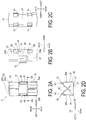
- a clip 1 illustrated in FIGS. 1A, 1B , and 2A to 2D is surface mounted to a conductive portion of a printed wiring board by soldering, and functions as a clip that sandwiches and holds an insert serving as the object to be held on the printed wiring board.
- the conductive portion corresponds to a portion of the printed wiring such as a copper layer that connects electronic parts mounted to the printed wiring board.
- the insert described above is a conductive member, the conductive portion described above and the insert can be electrically connected.
- the clip 1 is conceivably formed by press-processing a sheet metal having electrical conductivity. Note that the material and formation method of the clip 1 are not particularly limited.
- the clip 1 includes a base portion 11, holding portions 13, guiding portions 15, and the like. While the configuration of the clip 1 is hereinafter described using directions such as front-back, up-down, and left-right for the sake of convenience, these directions are merely defined for explaining the positional relationship of each component and do not limit the way the clip 1 is attached, the form of use, or the like.
- the base portion 11 is a member that has a plate shape and extends in the front-back direction and the left-right direction.
- the base portion 11 includes a joining surface 21 soldered to a conductive portion of the printed wiring board described above on a lower side. That is, the base portion 11 is a portion disposed along the printed wiring board on the printed wiring board.
- the joining surface 21 is an example of the joining portion.
- An upper surface of the base portion 11 can be utilized as a suction surface for suctioning by a suction nozzle.
- the portion of the base portion 11 visible between two guiding portions 15 may be used as the suction surface.
- the holding portions 13 being disposed in the front and back of this portion is convenient because, when being used as a suction surface, the portion does not readily cause a balance of the clip 1 to collapse.
- the suction surface may be used for removing the clip 1 housed in an embossed carrier tape from the embossed carrier tape, for example.
- the holding portions 13 each include a pair of spring pieces 23 that are connected to the base portion 11 and face each other.
- the pair of spring pieces 23 include a first spring piece 23a disposed on the right side, and a second spring piece 23b disposed on the left side.
- the first spring piece 23a and the second spring piece 23b are symmetrical in relation to planes extending in the up-down direction and the front-back direction.
- the pair of spring pieces 23 refers to both the first spring piece 23a and the second spring piece 23b. Further, “one spring piece 23” refers to one spring piece without distinction between the first spring piece 23a and the second spring piece 23b.
- the holding portions 13 each sandwich and hold an insert described later inserted between the first spring piece 23a and the second spring piece 23b of the pair of spring pieces 23 by the first spring piece 23a and the second spring piece 23b. That is, the holding portions 13 can fix the insert in a predetermined position on the printed wiring board. While the holding portions 13 are formed at two locations on ends of the base portion 11 in the front-back direction as described above, the holding portions 13 are symmetrical in relation to planes extending in the up-down direction and the left-right direction.
- Each of the one spring pieces 23 constituting the holding portion 13 includes a first portion 31, a second portion 33, and a leading edge portion 35.
- the first portion 31 extends in a direction that intersects the base portion 11, in other words, in a direction that intersects the joining surface 21, specifically upward.
- the second portion 33 bends at an end portion on an upper side of the first portion 31, connects with the first portion 31, and extends in a direction toward the corresponding one spring piece 23 of the one spring piece 23 as well as in a direction approaching the base portion 11.
- the end portion on the upper side of the first portion 31 described above is the end portion opposite to the end portion of the first portion 31 that is connected with the base portion 11.
- the second portion 33 extends from the upper right to the lower left in the first spring piece 23a, and from the upper left to the lower right in the second spring piece 23b.
- the second portion 33 described above is connected to the first portion 31 in a bent manner from the first portion 31.
- a bent portion exists between the first portion 31 and the second portion 33, and an incline between the first portion 31 and the second portion 33 changes in at least the bent portion.
- neither the first portion 31 nor the second portion 33 need to have a planar shape, and may have a curved shape.
- the leading edge portion 35 bends at the extended leading edge of the second portion 33, connects with the second portion 33, and extends downward and in a direction opposite to the corresponding one spring piece 23 described above.
- Each of the one spring pieces 23 is configured to be elastically displaceable in a facing direction, which is the direction in which the first spring piece 23a and the second spring piece 23b are disposed side-by-side. In the present embodiment, the left-right direction is the facing direction.
- Two holding portions 13 are disposed side-by-side in a manner that allows a single member having a plate shape to be sandwiched from a front surface side and a rear surface side simultaneously. Specifically, the two holding portions 13 are disposed (i) on the same plane, (2) so that an insertion direction of the insert is downward, (iii) so that the facing direction is the left-right direction, and (iv) side-by-side in the front-back direction. The insertion direction will be described later.
- the guiding portions 15 each guide an insert 3 to a position between the pair of spring pieces 23 when the insert 3 is inserted into the holding portions 13. This position, more specifically, is between the second portions 33 of each of the one spring pieces 23, and is sandwiched between the pair of spring pieces 23.
- the guiding portions 15 each guide the insert to the left when the insert is positioned to the right of the position between the pair of spring pieces 23, and to the right when the insert is positioned to the left of the position between the pair of spring pieces 23.
- the guiding portions 15 each include a contact surface 41, which is a surface inclined downward toward a center of the clip 1 in the left-right direction, and a contact surface support portion 43 that supports the contact surface 41. The arrangement of the contact surface 41 will be described later.
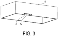
- the insert 3 is a member having a plate shape.
- the insert 3 constitutes a portion of a lower end of a box 5 that is open on a bottom side, as illustrated in FIG. 3 .
- a thickness of the insert 3 is greater than a space in the left-right direction between the first spring piece 23a and the second spring piece 23b.
- a slit 3a is formed in the insert 3.
- the slit 3a is an example of the insertion space.
- the two holding portions 13 sandwich the insert 3 from the front surface side and the rear surface side, respectively. In the process of this sandwiching, the two holding portions 13 operates in the same way, and thus only one will be described as representation. Note that the front surface side and the rear surface side here merely refer to one surface and the other surface of the main surfaces of the member having a plate shape, and do not signify any structural differences.
- This coupling portion 37 has a shape that is convex toward the corresponding spring piece 23 of the spring piece 23.
- This coupling portion 37 is an example of the convex portion.
- the coupling portion 37 may be formed only in one of the first spring piece 23a and the second spring piece 23b.
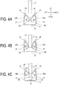
- the first spring piece 23a and the second spring piece 23b, in the state illustrated in FIG. 4C , are elastically deformed so as to be separated at a greater distance from each other than in the state illustrated in FIG. 4A in which no load is applied.
- the insert 3 receives an elastic force and is sandwiched by the pair of spring pieces 23.
- the second portion 33 is configured so as to incline from the upper right to the lower left.
- the insert 3 receives a leftward reactive force, slides to the lower left, and is guided to a position between the first spring piece 23a and the second spring piece 23b.
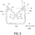
- the contact surface 41 is also a surface that inclines from the upper right to the lower left and thus, as illustrated in FIG. 5B , when the insert 3 moves in the insertion direction and comes into contact with the contact surface 41, the insert 3 receives a leftward reactive force, slides to the lower left, and is guided to a position between the first spring piece 23a and the second spring piece 23b.
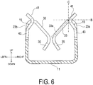
- the contact surface 41 on the right side is in a position farther away from the base portion 11 than the second portion 33 of the first spring piece 23a in relation to the insertion direction, that is, the up-down direction. That is, the contact surface 41 is positioned above a virtual line B in FIG. 6 . Further, the contact surface 41 is in a position farther away from the second spring piece 23b than the second portion 33 of the first spring piece 23a in relation to the facing direction, that is, the left-right direction. That is, the contact surface 41 is positioned to the right of a virtual line C. The contact surface 41 on the left side is also disposed in the same manner with respect to the second spring piece 23b.
- the contact surface 41 can expand the length of a width in the left-right direction in which the insert 3 can be guided from L1, which is a width executed by the pair of second portions 33 of the pair of spring pieces 23, that is, a length of the interval between the lines C, to L2, which is a width that includes the contact surfaces 41, that is, the length of the interval between virtual lines D.
- the contact surface 41 is provided between the two holding portions 13 in the direction in which the two holding portions 13 are disposed side-by-side, that is, the front-back direction.
- the effect of expanding the guidable width can be applied to both of the holding portions 13.
- through-holes 51 are formed in two locations spaced apart in the front-back direction, from the base portion 11 to a side wall surface 61 that includes the first portion 31, the contact surface 41, and the like of the two holding portions 13.
- the elastic force of one spring piece 23 is adjusted by these through-holes 51.
- the first portion 31 and the contact surface support portion 43 are connected by a connecting portion 53, increasing a rigidity of the contact surface support portion 43 and thus making it possible for the contact surface 41 to favorably execute guidance.
- the configuration of the second embodiment is fundamentally the same as the configuration of the first embodiment. As such, description will be focused on differences and description of configurations that are the same will be omitted. Note that reference numerals in the present embodiment that are the same as those used in the first embodiment refer to the same constituents, and reference is made to the preceding description.
- the second embodiment differs from the first embodiment in that a contact surface is formed on the spring pieces as well.
- a clip 101 includes two holding portions 103, and the holding portions 103 each include a pair of spring pieces 105.
- the pair of spring pieces 105 each include a first spring piece 105a and a second spring piece 105b.
- One spring piece 105 includes a first portion 111, a second portion 113, a third portion 115, and the like.
- the third portion 115 extends from the second portion 113 in a direction away from the base portion 11 and in a direction opposite to the direction toward the corresponding one spring piece 105 of the one spring piece 105.
- An upper surface of this third portion 115 is formed as a contact surface 117, which is a surface that inclines downward toward a center of the clip 101 in the left-right direction.
- the third portion 115 is an example of the guiding portion.
- the contact surface 117 is positioned on the same plane as the upper surface of the second portion 113.
- the contact surface 117 formed on the first spring piece 105a is configured so that at least a portion thereof is in a position farther away from the base portion 11 than the second portion 113 of the first spring piece 105a in relation to the insertion direction. Further, the contact surface 117 is configured to be in a position farther away from the second spring piece 105b than the second portion 113 of the first spring piece 105a in relation to the facing direction.
- a portion of the contact surface 117 is positioned above the line B and to the right of the line C.
- the configuration may be such that the contact surface 117 is formed on at least one spring piece 105.
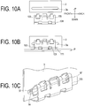
- the slit 3a may be formed longer than a width from a front end of the spring piece 105 on the front side to a back end of the spring piece 105 on the back side, that is, longer than a length that includes the two coupling portions 37 inserted into the slit 3a.
- the coupling portion 37 of one spring piece 105 is inserted into the slit 3a even when an insertion position of the insert 3 is shifted frontward or backward during assembly. Further, the insert 3 can be fixed to a suitable position with respect to a printed wiring board P even when the attachment position of the clip 101 is slightly shifted frontward or backward with respect to the printed wiring board P.
- FIGS. 10A to 10C illustrate an example of a configuration in which the two coupling portions 37 are inserted into one slit 3a
- the slit 3a may be individually formed so as to correspond to each of the coupling portions 37.
- the length of the slit 3a in the front-back direction may be configured to be substantially equal to the width of one coupling portion 37, with only a slight amount of clearance during insertion. Further, the length of the slit 3a in the front-back direction may be configured to be substantially equal to the length from a front end of the coupling portion 37 positioned most frontward of the plurality of coupling portions 37, to a rear end of the coupling portion 37 positioned most backward. With the slit 3a and the coupling portions 37 thus configured, it is possible to achieve positioning after assembly of the insert 3.
- the slit 3a may have a shape that does not extend all of the way through. That is, a space such as a groove or a hole that allows insertion of the coupling portion 37 when the first spring piece and the second spring piece sandwich the insert 3 need only be formed on at least one of the front surface and the rear surface of the insert 3.
- the slit 3a may be configured so that at least one coupling portion 37 is inserted therein. Further, when the length of the slit 3a is made sufficiently long compared to the coupling portion 37, the configuration may be such that one or more coupling portions 37 are inserted into the slit 3a, or one or more coupling portions 37 are not inserted into the slit 3a.
- the slit 3a may be divided and formed in a plurality of positions. For example, conceivably a plurality of the slits 3a may be disposed side-by-side in the length direction of the slit 3a.
- the clip may be configured so that the coupling portions 37 are inserted into one or more of the slits 3a.
- the clip may be configured so that one or more of the coupling portions 37 are inserted into one of the slits 3a. That is, the clip may be configured so that a plurality of the slits 3a are formed in the insert 3, a plurality of the holding portions are formed in the clip, and one of the connecting portions 37 is inserted into one of the slits 3a.
Landscapes
- Engineering & Computer Science (AREA)
- General Engineering & Computer Science (AREA)
- Microelectronics & Electronic Packaging (AREA)
- Mechanical Engineering (AREA)
- Clamps And Clips (AREA)
- Shielding Devices Or Components To Electric Or Magnetic Fields (AREA)
Applications Claiming Priority (2)
| Application Number | Priority Date | Filing Date | Title |
|---|---|---|---|
| JP2015253813A JP6754031B2 (ja) | 2015-12-25 | 2015-12-25 | クリップ及び固定機構 |
| PCT/JP2016/088425 WO2017111051A1 (fr) | 2015-12-25 | 2016-12-22 | Organe de fixation et mécanisme de fixation |
Publications (3)
| Publication Number | Publication Date |
|---|---|
| EP3396178A1 true EP3396178A1 (fr) | 2018-10-31 |
| EP3396178A4 EP3396178A4 (fr) | 2019-08-21 |
| EP3396178B1 EP3396178B1 (fr) | 2022-04-27 |
Family
ID=59090520
Family Applications (1)
| Application Number | Title | Priority Date | Filing Date |
|---|---|---|---|
| EP16878937.8A Active EP3396178B1 (fr) | 2015-12-25 | 2016-12-22 | Organe de fixation et mécanisme de fixation |
Country Status (5)
| Country | Link |
|---|---|
| US (1) | US10251296B2 (fr) |
| EP (1) | EP3396178B1 (fr) |
| JP (1) | JP6754031B2 (fr) |
| CN (1) | CN108463638B (fr) |
| WO (1) | WO2017111051A1 (fr) |
Families Citing this family (18)
| Publication number | Priority date | Publication date | Assignee | Title |
|---|---|---|---|---|
| DE102017104981B4 (de) * | 2017-03-09 | 2021-01-28 | Schaeffler Technologies AG & Co. KG | Befestigungsmittel eines Aktuators einer Nockenwellenverstellvorrichtung |
| CN111051710B (zh) | 2017-07-11 | 2022-03-08 | 伊利诺斯工具制品有限公司 | 边缘保护器 |
| DE202017104834U1 (de) * | 2017-08-10 | 2017-09-11 | SMR Patents S.à.r.l. | Montageanordnung für ein Außenanbauteil, Rückblickvorrichtung und Kraftfahrzeug |
| DE102017214910A1 (de) * | 2017-08-25 | 2019-02-28 | Siemens Mobility GmbH | Sicherungselement und Verliersicherungssystem |
| JP2019096646A (ja) * | 2017-11-17 | 2019-06-20 | 株式会社デンソー | 電子機器 |
| CN109378264B (zh) * | 2018-10-11 | 2021-01-26 | 广东美的厨房电器制造有限公司 | 用于磁控管的散热组件和具有其的磁控管 |
| JP1659434S (fr) * | 2019-06-04 | 2020-05-18 | ||
| CN110594602A (zh) * | 2019-09-17 | 2019-12-20 | 厦门通士达照明有限公司 | 一种灯丝灯导线插接结构及灯丝灯 |
| CN110469065B (zh) * | 2019-09-18 | 2024-10-18 | 正泰新能科技股份有限公司 | 一种光伏组件 |
| USD924150S1 (en) * | 2019-11-26 | 2021-07-06 | Molex, Llc | Connector |
| WO2021146609A1 (fr) * | 2020-01-17 | 2021-07-22 | Illinois Tool Works Inc. | Pince de rétention en métal |
| USD910427S1 (en) * | 2020-05-27 | 2021-02-16 | Guangzhou Diyang Cultural Diffusion Co., Ltd | Fastener |
| USD971711S1 (en) * | 2020-09-18 | 2022-12-06 | Allied Bolt, Inc. | Prong for a clip |
| USD972394S1 (en) * | 2020-09-18 | 2022-12-13 | Allied Bolt, Inc. | Prongs for a clip |
| US12564673B2 (en) * | 2020-11-10 | 2026-03-03 | Dauntless Innovations, LLC | Slack release system for medical tubing |
| JP7502162B2 (ja) * | 2020-11-30 | 2024-06-18 | 京セラ株式会社 | 接続部品、シールドモジュール、及び電子機器 |
| CN115092026A (zh) * | 2022-06-30 | 2022-09-23 | 东风汽车集团股份有限公司 | 一种单滑轨扶手及汽车 |
| CN119214443A (zh) * | 2024-08-22 | 2024-12-31 | 元鼎饰材实业(镇江)有限公司 | 一种柔纱帘结构 |
Family Cites Families (14)
| Publication number | Priority date | Publication date | Assignee | Title |
|---|---|---|---|---|
| US4647123A (en) * | 1983-02-07 | 1987-03-03 | Gulf & Western Manufacturing Company | Bus networks for digital data processing systems and modules usable therewith |
| JPH09223527A (ja) * | 1996-02-19 | 1997-08-26 | Kitagawa Ind Co Ltd | 導通クリップ |
| TW588478B (en) * | 1999-09-16 | 2004-05-21 | Shinetsu Polymer Co | Method for electrically connecting two sets of electrode terminals in array on electronic board units |
| US6508664B2 (en) * | 2001-05-09 | 2003-01-21 | Delphi Technologies, Inc. | Connectors for circuit boards configured with foil on both sides |
| JP3609762B2 (ja) | 2001-08-06 | 2005-01-12 | 北川工業株式会社 | シールドボックスの実装方法 |
| US8066515B2 (en) * | 2004-11-17 | 2011-11-29 | Nvidia Corporation | Multiple graphics adapter connection systems |
| KR20080006504A (ko) * | 2007-08-17 | 2008-01-16 | 주식회사 포콘스 | 인쇄회로기판용 차폐케이스 고정기구 |
| KR100886591B1 (ko) | 2007-11-01 | 2009-03-05 | 주식회사 포콘스 | 쉴드캔 고정용 클립 |
| CN102348900B (zh) * | 2009-03-11 | 2013-07-17 | 伊利诺斯工具制品有限公司 | 紧固装置 |
| JP5200079B2 (ja) * | 2010-09-21 | 2013-05-15 | 本田技研工業株式会社 | クランプ部材 |
| KR101029221B1 (ko) * | 2011-01-14 | 2011-04-14 | 에프엔티주식회사 | 부분 도금층이 마련된 전자파 차단용 쉴드캔 고정클립 |
| KR20120094653A (ko) * | 2011-02-17 | 2012-08-27 | 주식회사 니프코코리아 | 플라스틱 클립 |
| JP2013168508A (ja) * | 2012-02-15 | 2013-08-29 | Seiwa Electric Mfg Co Ltd | 表面実装クリップ |
| JP2015012151A (ja) * | 2013-06-28 | 2015-01-19 | 北川工業株式会社 | シールドケース把持部材 |
-
2015
- 2015-12-25 JP JP2015253813A patent/JP6754031B2/ja active Active
-
2016
- 2016-12-22 US US16/066,013 patent/US10251296B2/en active Active
- 2016-12-22 EP EP16878937.8A patent/EP3396178B1/fr active Active
- 2016-12-22 CN CN201680066032.9A patent/CN108463638B/zh active Active
- 2016-12-22 WO PCT/JP2016/088425 patent/WO2017111051A1/fr not_active Ceased
Also Published As
| Publication number | Publication date |
|---|---|
| CN108463638A (zh) | 2018-08-28 |
| CN108463638B (zh) | 2020-04-21 |
| JP6754031B2 (ja) | 2020-09-09 |
| US20190014676A1 (en) | 2019-01-10 |
| EP3396178B1 (fr) | 2022-04-27 |
| JP2017118002A (ja) | 2017-06-29 |
| WO2017111051A1 (fr) | 2017-06-29 |
| EP3396178A4 (fr) | 2019-08-21 |
| US10251296B2 (en) | 2019-04-02 |
Similar Documents
| Publication | Publication Date | Title |
|---|---|---|
| US10251296B2 (en) | Clip and fixing mechanism | |
| KR101358281B1 (ko) | 표면 실장 클립 | |
| KR101658765B1 (ko) | 금속 셸에 큰 개구를 형성함이 없이 희망 마찰 로크를 용이하게 획득할 수 있는 리셉터클 커넥터 | |
| CN104638403B (zh) | 电连接器 | |
| US8915760B2 (en) | Surface mount clip | |
| EP3540864B1 (fr) | Connecteur mobile | |
| JP6540674B2 (ja) | 電気コネクタ | |
| US9472903B2 (en) | Grip member | |
| US9549491B2 (en) | Conductive clip | |
| JP7002432B2 (ja) | コネクタ及びコネクタの製造方法 | |
| US20160120024A1 (en) | Linear Conductor Connection Terminal | |
| JP7195589B2 (ja) | 固定具 | |
| JP6184022B2 (ja) | コネクタ及びコネクタ組立体 | |
| JP2015002094A (ja) | フラットケーブル端末接続具 | |
| JP7154579B2 (ja) | コンタクト | |
| JP6613129B2 (ja) | 金属端子 | |
| JP2007242346A (ja) | 物品取付装置 | |
| JP6527407B2 (ja) | アンテナ装置 | |
| CN119851567A (zh) | 柔性布线基板的限制装置及使用所述限制装置的显示装置 | |
| JP2023131207A (ja) | 電気部品支持構造 | |
| JP2001332341A (ja) | コネクタの接続構造 | |
| WO2018212240A1 (fr) | Outil de fixation | |
| JPH11233972A (ja) | 印刷配線板の固定構造 | |
| JP2009004549A (ja) | プリント基板用のガイドレール |
Legal Events
| Date | Code | Title | Description |
|---|---|---|---|
| STAA | Information on the status of an ep patent application or granted ep patent |
Free format text: STATUS: THE INTERNATIONAL PUBLICATION HAS BEEN MADE |
|
| PUAI | Public reference made under article 153(3) epc to a published international application that has entered the european phase |
Free format text: ORIGINAL CODE: 0009012 |
|
| STAA | Information on the status of an ep patent application or granted ep patent |
Free format text: STATUS: REQUEST FOR EXAMINATION WAS MADE |
|
| 17P | Request for examination filed |
Effective date: 20180615 |
|
| AK | Designated contracting states |
Kind code of ref document: A1 Designated state(s): AL AT BE BG CH CY CZ DE DK EE ES FI FR GB GR HR HU IE IS IT LI LT LU LV MC MK MT NL NO PL PT RO RS SE SI SK SM TR |
|
| AX | Request for extension of the european patent |
Extension state: BA ME |
|
| DAV | Request for validation of the european patent (deleted) | ||
| DAX | Request for extension of the european patent (deleted) | ||
| A4 | Supplementary search report drawn up and despatched |
Effective date: 20190719 |
|
| RIC1 | Information provided on ipc code assigned before grant |
Ipc: H05K 9/00 20060101ALI20190715BHEP Ipc: H05K 7/12 20060101ALI20190715BHEP Ipc: H05K 1/18 20060101ALI20190715BHEP Ipc: F16B 2/24 20060101AFI20190715BHEP Ipc: F16B 5/06 20060101ALI20190715BHEP |
|
| RIC1 | Information provided on ipc code assigned before grant |
Ipc: F16B 2/24 20060101AFI20200128BHEP Ipc: H05K 7/12 20060101ALI20200128BHEP Ipc: F16B 5/06 20060101ALI20200128BHEP Ipc: H05K 9/00 20060101ALI20200128BHEP Ipc: H05K 1/18 20060101ALI20200128BHEP |
|
| GRAP | Despatch of communication of intention to grant a patent |
Free format text: ORIGINAL CODE: EPIDOSNIGR1 |
|
| STAA | Information on the status of an ep patent application or granted ep patent |
Free format text: STATUS: GRANT OF PATENT IS INTENDED |
|
| INTG | Intention to grant announced |
Effective date: 20211210 |
|
| GRAS | Grant fee paid |
Free format text: ORIGINAL CODE: EPIDOSNIGR3 |
|
| GRAA | (expected) grant |
Free format text: ORIGINAL CODE: 0009210 |
|
| STAA | Information on the status of an ep patent application or granted ep patent |
Free format text: STATUS: THE PATENT HAS BEEN GRANTED |
|
| AK | Designated contracting states |
Kind code of ref document: B1 Designated state(s): AL AT BE BG CH CY CZ DE DK EE ES FI FR GB GR HR HU IE IS IT LI LT LU LV MC MK MT NL NO PL PT RO RS SE SI SK SM TR |
|
| REG | Reference to a national code |
Ref country code: GB Ref legal event code: FG4D |
|
| REG | Reference to a national code |
Ref country code: CH Ref legal event code: EP |
|
| REG | Reference to a national code |
Ref country code: AT Ref legal event code: REF Ref document number: 1487125 Country of ref document: AT Kind code of ref document: T Effective date: 20220515 |
|
| REG | Reference to a national code |
Ref country code: DE Ref legal event code: R096 Ref document number: 602016071604 Country of ref document: DE |
|
| REG | Reference to a national code |
Ref country code: IE Ref legal event code: FG4D |
|
| REG | Reference to a national code |
Ref country code: LT Ref legal event code: MG9D |
|
| REG | Reference to a national code |
Ref country code: NL Ref legal event code: MP Effective date: 20220427 |
|
| REG | Reference to a national code |
Ref country code: AT Ref legal event code: MK05 Ref document number: 1487125 Country of ref document: AT Kind code of ref document: T Effective date: 20220427 |
|
| PG25 | Lapsed in a contracting state [announced via postgrant information from national office to epo] |
Ref country code: NL Free format text: LAPSE BECAUSE OF FAILURE TO SUBMIT A TRANSLATION OF THE DESCRIPTION OR TO PAY THE FEE WITHIN THE PRESCRIBED TIME-LIMIT Effective date: 20220427 |
|
| PG25 | Lapsed in a contracting state [announced via postgrant information from national office to epo] |
Ref country code: SE Free format text: LAPSE BECAUSE OF FAILURE TO SUBMIT A TRANSLATION OF THE DESCRIPTION OR TO PAY THE FEE WITHIN THE PRESCRIBED TIME-LIMIT Effective date: 20220427 Ref country code: PT Free format text: LAPSE BECAUSE OF FAILURE TO SUBMIT A TRANSLATION OF THE DESCRIPTION OR TO PAY THE FEE WITHIN THE PRESCRIBED TIME-LIMIT Effective date: 20220829 Ref country code: NO Free format text: LAPSE BECAUSE OF FAILURE TO SUBMIT A TRANSLATION OF THE DESCRIPTION OR TO PAY THE FEE WITHIN THE PRESCRIBED TIME-LIMIT Effective date: 20220727 Ref country code: LT Free format text: LAPSE BECAUSE OF FAILURE TO SUBMIT A TRANSLATION OF THE DESCRIPTION OR TO PAY THE FEE WITHIN THE PRESCRIBED TIME-LIMIT Effective date: 20220427 Ref country code: HR Free format text: LAPSE BECAUSE OF FAILURE TO SUBMIT A TRANSLATION OF THE DESCRIPTION OR TO PAY THE FEE WITHIN THE PRESCRIBED TIME-LIMIT Effective date: 20220427 Ref country code: GR Free format text: LAPSE BECAUSE OF FAILURE TO SUBMIT A TRANSLATION OF THE DESCRIPTION OR TO PAY THE FEE WITHIN THE PRESCRIBED TIME-LIMIT Effective date: 20220728 Ref country code: FI Free format text: LAPSE BECAUSE OF FAILURE TO SUBMIT A TRANSLATION OF THE DESCRIPTION OR TO PAY THE FEE WITHIN THE PRESCRIBED TIME-LIMIT Effective date: 20220427 Ref country code: ES Free format text: LAPSE BECAUSE OF FAILURE TO SUBMIT A TRANSLATION OF THE DESCRIPTION OR TO PAY THE FEE WITHIN THE PRESCRIBED TIME-LIMIT Effective date: 20220427 Ref country code: BG Free format text: LAPSE BECAUSE OF FAILURE TO SUBMIT A TRANSLATION OF THE DESCRIPTION OR TO PAY THE FEE WITHIN THE PRESCRIBED TIME-LIMIT Effective date: 20220727 Ref country code: AT Free format text: LAPSE BECAUSE OF FAILURE TO SUBMIT A TRANSLATION OF THE DESCRIPTION OR TO PAY THE FEE WITHIN THE PRESCRIBED TIME-LIMIT Effective date: 20220427 |
|
| PG25 | Lapsed in a contracting state [announced via postgrant information from national office to epo] |
Ref country code: RS Free format text: LAPSE BECAUSE OF FAILURE TO SUBMIT A TRANSLATION OF THE DESCRIPTION OR TO PAY THE FEE WITHIN THE PRESCRIBED TIME-LIMIT Effective date: 20220427 Ref country code: PL Free format text: LAPSE BECAUSE OF FAILURE TO SUBMIT A TRANSLATION OF THE DESCRIPTION OR TO PAY THE FEE WITHIN THE PRESCRIBED TIME-LIMIT Effective date: 20220427 Ref country code: LV Free format text: LAPSE BECAUSE OF FAILURE TO SUBMIT A TRANSLATION OF THE DESCRIPTION OR TO PAY THE FEE WITHIN THE PRESCRIBED TIME-LIMIT Effective date: 20220427 Ref country code: IS Free format text: LAPSE BECAUSE OF FAILURE TO SUBMIT A TRANSLATION OF THE DESCRIPTION OR TO PAY THE FEE WITHIN THE PRESCRIBED TIME-LIMIT Effective date: 20220827 |
|
| REG | Reference to a national code |
Ref country code: DE Ref legal event code: R097 Ref document number: 602016071604 Country of ref document: DE |
|
| PG25 | Lapsed in a contracting state [announced via postgrant information from national office to epo] |
Ref country code: SM Free format text: LAPSE BECAUSE OF FAILURE TO SUBMIT A TRANSLATION OF THE DESCRIPTION OR TO PAY THE FEE WITHIN THE PRESCRIBED TIME-LIMIT Effective date: 20220427 Ref country code: SK Free format text: LAPSE BECAUSE OF FAILURE TO SUBMIT A TRANSLATION OF THE DESCRIPTION OR TO PAY THE FEE WITHIN THE PRESCRIBED TIME-LIMIT Effective date: 20220427 Ref country code: RO Free format text: LAPSE BECAUSE OF FAILURE TO SUBMIT A TRANSLATION OF THE DESCRIPTION OR TO PAY THE FEE WITHIN THE PRESCRIBED TIME-LIMIT Effective date: 20220427 Ref country code: EE Free format text: LAPSE BECAUSE OF FAILURE TO SUBMIT A TRANSLATION OF THE DESCRIPTION OR TO PAY THE FEE WITHIN THE PRESCRIBED TIME-LIMIT Effective date: 20220427 Ref country code: DK Free format text: LAPSE BECAUSE OF FAILURE TO SUBMIT A TRANSLATION OF THE DESCRIPTION OR TO PAY THE FEE WITHIN THE PRESCRIBED TIME-LIMIT Effective date: 20220427 Ref country code: CZ Free format text: LAPSE BECAUSE OF FAILURE TO SUBMIT A TRANSLATION OF THE DESCRIPTION OR TO PAY THE FEE WITHIN THE PRESCRIBED TIME-LIMIT Effective date: 20220427 |
|
| PLBE | No opposition filed within time limit |
Free format text: ORIGINAL CODE: 0009261 |
|
| STAA | Information on the status of an ep patent application or granted ep patent |
Free format text: STATUS: NO OPPOSITION FILED WITHIN TIME LIMIT |
|
| PG25 | Lapsed in a contracting state [announced via postgrant information from national office to epo] |
Ref country code: AL Free format text: LAPSE BECAUSE OF FAILURE TO SUBMIT A TRANSLATION OF THE DESCRIPTION OR TO PAY THE FEE WITHIN THE PRESCRIBED TIME-LIMIT Effective date: 20220427 |
|
| 26N | No opposition filed |
Effective date: 20230130 |
|
| PG25 | Lapsed in a contracting state [announced via postgrant information from national office to epo] |
Ref country code: SI Free format text: LAPSE BECAUSE OF FAILURE TO SUBMIT A TRANSLATION OF THE DESCRIPTION OR TO PAY THE FEE WITHIN THE PRESCRIBED TIME-LIMIT Effective date: 20220427 |
|
| REG | Reference to a national code |
Ref country code: CH Ref legal event code: PL |
|
| GBPC | Gb: european patent ceased through non-payment of renewal fee |
Effective date: 20221222 |
|
| REG | Reference to a national code |
Ref country code: BE Ref legal event code: MM Effective date: 20221231 |
|
| PG25 | Lapsed in a contracting state [announced via postgrant information from national office to epo] |
Ref country code: LU Free format text: LAPSE BECAUSE OF NON-PAYMENT OF DUE FEES Effective date: 20221222 |
|
| PG25 | Lapsed in a contracting state [announced via postgrant information from national office to epo] |
Ref country code: LI Free format text: LAPSE BECAUSE OF NON-PAYMENT OF DUE FEES Effective date: 20221231 Ref country code: IE Free format text: LAPSE BECAUSE OF NON-PAYMENT OF DUE FEES Effective date: 20221222 Ref country code: GB Free format text: LAPSE BECAUSE OF NON-PAYMENT OF DUE FEES Effective date: 20221222 Ref country code: CH Free format text: LAPSE BECAUSE OF NON-PAYMENT OF DUE FEES Effective date: 20221231 |
|
| PG25 | Lapsed in a contracting state [announced via postgrant information from national office to epo] |
Ref country code: FR Free format text: LAPSE BECAUSE OF NON-PAYMENT OF DUE FEES Effective date: 20221231 Ref country code: BE Free format text: LAPSE BECAUSE OF NON-PAYMENT OF DUE FEES Effective date: 20221231 |
|
| PG25 | Lapsed in a contracting state [announced via postgrant information from national office to epo] |
Ref country code: IT Free format text: LAPSE BECAUSE OF FAILURE TO SUBMIT A TRANSLATION OF THE DESCRIPTION OR TO PAY THE FEE WITHIN THE PRESCRIBED TIME-LIMIT Effective date: 20220427 |
|
| PG25 | Lapsed in a contracting state [announced via postgrant information from national office to epo] |
Ref country code: HU Free format text: LAPSE BECAUSE OF FAILURE TO SUBMIT A TRANSLATION OF THE DESCRIPTION OR TO PAY THE FEE WITHIN THE PRESCRIBED TIME-LIMIT; INVALID AB INITIO Effective date: 20161222 |
|
| PG25 | Lapsed in a contracting state [announced via postgrant information from national office to epo] |
Ref country code: CY Free format text: LAPSE BECAUSE OF FAILURE TO SUBMIT A TRANSLATION OF THE DESCRIPTION OR TO PAY THE FEE WITHIN THE PRESCRIBED TIME-LIMIT Effective date: 20220427 |
|
| PG25 | Lapsed in a contracting state [announced via postgrant information from national office to epo] |
Ref country code: MK Free format text: LAPSE BECAUSE OF FAILURE TO SUBMIT A TRANSLATION OF THE DESCRIPTION OR TO PAY THE FEE WITHIN THE PRESCRIBED TIME-LIMIT Effective date: 20220427 |
|
| PG25 | Lapsed in a contracting state [announced via postgrant information from national office to epo] |
Ref country code: MC Free format text: LAPSE BECAUSE OF FAILURE TO SUBMIT A TRANSLATION OF THE DESCRIPTION OR TO PAY THE FEE WITHIN THE PRESCRIBED TIME-LIMIT Effective date: 20220427 |
|
| PG25 | Lapsed in a contracting state [announced via postgrant information from national office to epo] |
Ref country code: TR Free format text: LAPSE BECAUSE OF FAILURE TO SUBMIT A TRANSLATION OF THE DESCRIPTION OR TO PAY THE FEE WITHIN THE PRESCRIBED TIME-LIMIT Effective date: 20220427 Ref country code: MC Free format text: LAPSE BECAUSE OF FAILURE TO SUBMIT A TRANSLATION OF THE DESCRIPTION OR TO PAY THE FEE WITHIN THE PRESCRIBED TIME-LIMIT Effective date: 20220427 |
|
| PG25 | Lapsed in a contracting state [announced via postgrant information from national office to epo] |
Ref country code: MT Free format text: LAPSE BECAUSE OF FAILURE TO SUBMIT A TRANSLATION OF THE DESCRIPTION OR TO PAY THE FEE WITHIN THE PRESCRIBED TIME-LIMIT Effective date: 20220427 |
|
| PG25 | Lapsed in a contracting state [announced via postgrant information from national office to epo] |
Ref country code: BG Free format text: LAPSE BECAUSE OF FAILURE TO SUBMIT A TRANSLATION OF THE DESCRIPTION OR TO PAY THE FEE WITHIN THE PRESCRIBED TIME-LIMIT Effective date: 20220427 |
|
| PG25 | Lapsed in a contracting state [announced via postgrant information from national office to epo] |
Ref country code: BG Free format text: LAPSE BECAUSE OF FAILURE TO SUBMIT A TRANSLATION OF THE DESCRIPTION OR TO PAY THE FEE WITHIN THE PRESCRIBED TIME-LIMIT Effective date: 20220427 |
|
| PGFP | Annual fee paid to national office [announced via postgrant information from national office to epo] |
Ref country code: DE Payment date: 20251211 Year of fee payment: 10 |